JP3902109B2 - Infrared camera characteristics confirmation jig - Google Patents
Infrared camera characteristics confirmation jigDownload PDFInfo
- Publication number
- JP3902109B2 JP3902109B2JP2002290234AJP2002290234AJP3902109B2JP 3902109 B2JP3902109 B2JP 3902109B2JP 2002290234 AJP2002290234 AJP 2002290234AJP 2002290234 AJP2002290234 AJP 2002290234AJP 3902109 B2JP3902109 B2JP 3902109B2
- Authority
- JP
- Japan
- Prior art keywords
- infrared
- infrared camera
- cover plate
- radiation source
- measured
- Prior art date
- Legal status (The legal status is an assumption and is not a legal conclusion. Google has not performed a legal analysis and makes no representation as to the accuracy of the status listed.)
- Expired - Fee Related
Links
Images


Classifications
- H—ELECTRICITY
- H04—ELECTRIC COMMUNICATION TECHNIQUE
- H04N—PICTORIAL COMMUNICATION, e.g. TELEVISION
- H04N17/00—Diagnosis, testing or measuring for television systems or their details
- H04N17/002—Diagnosis, testing or measuring for television systems or their details for television cameras
- H—ELECTRICITY
- H04—ELECTRIC COMMUNICATION TECHNIQUE
- H04N—PICTORIAL COMMUNICATION, e.g. TELEVISION
- H04N13/00—Stereoscopic video systems; Multi-view video systems; Details thereof
- H04N13/20—Image signal generators
- H04N13/204—Image signal generators using stereoscopic image cameras
- H04N13/246—Calibration of cameras
- H—ELECTRICITY
- H04—ELECTRIC COMMUNICATION TECHNIQUE
- H04N—PICTORIAL COMMUNICATION, e.g. TELEVISION
- H04N23/00—Cameras or camera modules comprising electronic image sensors; Control thereof
- H04N23/20—Cameras or camera modules comprising electronic image sensors; Control thereof for generating image signals from infrared radiation only
Landscapes
- Engineering & Computer Science (AREA)
- Multimedia (AREA)
- Signal Processing (AREA)
- Health & Medical Sciences (AREA)
- Biomedical Technology (AREA)
- General Health & Medical Sciences (AREA)
- Length Measuring Devices By Optical Means (AREA)
- Measurement Of Optical Distance (AREA)
- Photometry And Measurement Of Optical Pulse Characteristics (AREA)
- Geophysics And Detection Of Objects (AREA)
- Testing, Inspecting, Measuring Of Stereoscopic Televisions And Televisions (AREA)
Description
Translated fromJapanese【0001】
【発明の属する技術分野】
この発明は、車両に搭載された対象物測距用の赤外線カメラの特性確認を行うための赤外線カメラ特性確認治具に関する。
【0002】
【従来の技術】
従来、2台のカメラ(ステレオカメラ)により撮影された1対の対象物画像の視差を利用して、該対象物までの距離を求める3次元計測技術がある。このような技術では、レンズ歪や焦点距離のバラツキによる位置ずれ補正を行い正確な対象物距離を求めるために、画像補正装置が必要となる。このようなステレオカメラの画像補正装置は、予め、正格子パターンのような特定の補正量計測用撮像パターンを、ステレオカメラの両カメラで同時に撮像し、それぞれのカメラの撮像画像について画素毎の座標補正量を計算する。そして、この結果を座標補正テーブルとして保持すると共に、画像メモリに格納されたデータを該座標補正テーブルの補正量により画素毎に補正することで、正確な画像データを取得する。なお、この時、レンズ歪や焦点距離のバラツキによる位置ずれ補正は垂直方向のみ行われる(例えば、特許文献1参照。)。
【0003】
【特許文献1】
特開平11−325889号公報
【0004】
【発明が解決しようとする課題】
ところで、上述のようなステレオカメラによる3次元計測技術の応用例としては、車両の前方に存在する障害物を車両の運転者よりも早期に発見し、これを運転者に通知するものがある。この場合、特に夜間の走行にも対応できるように、通常ステレオカメラには赤外線を撮影可能な赤外線カメラが用いられる。
しかし、従来の技術では、レンズ歪や焦点距離のバラツキによる位置ずれ補正を行うために、予め、正格子パターンのような特定の補正量計測用撮像パターンをステレオカメラの両カメラで同時に撮像し、それぞれのカメラの撮像画像について画素毎の座標補正量を計算する必要があるのに対し、ステレオカメラに赤外線カメラを用いる場合、赤外線カメラにより正確に撮影することができる正格子パターンを実現することが難しいという問題があった。
【0005】
本発明は、上記課題に鑑みてなされたもので、画像の水平方向と垂直方向の両方向に発生する対象物投影座標誤差を容易に測定することができる赤外線カメラ特性確認治具を提供することを目的とする。
【0006】
【課題を解決するための手段】
上記課題を解決するために、請求項1の発明に係る赤外線カメラ特性確認治具は、赤外線カメラを被測定物として、該赤外線カメラの特性確認を行うための赤外線カメラ特性確認治具であって、複数の孔(例えば実施の形態のターゲット孔H1〜H11)を一列に備えたカバープレート(例えば実施の形態の前面板3)と、前記被測定物の側から見て前記カバープレートの後方に、前記カバープレートと並行になるように配置されると共に、前記カバープレートとは異なる量の赤外線を放射する放射源(例えば実施の形態の背面板2及び温度調節器6)とを備え、前記カバープレートは、赤外線反射を抑制する加工(例えば実施の形態の起毛紙3a貼付)が施されていることを特徴とする。
【0007】
以上の構成を備えた赤外線カメラ特性確認治具は、複数の孔を一列に備えたカバープレートの後方に、該カバープレートと平行になるように放射源を配置し、該放射源からカバープレートより強い赤外線を放射することにより、カバープレートの孔を通過した赤外線によって、一様に並んだ複数の赤外線放射部を作成することができる。また、放射源からカバープレートより弱い赤外線を放射することにより、カバープレートの孔以外の部分から放射された赤外線との差によって、一様に並んだ複数の赤外線非放射部を作成することができる。
また、カバープレートに赤外線反射を抑制する加工を施すことにより、放射源から放射された赤外線が、特性確認を行う赤外線カメラの搭載された車両に反射し、更に反射した赤外線がカバープレートに再反射することを抑制することができる。
【0008】
請求項2の発明に係る赤外線カメラ特性確認治具は、請求項1に記載の赤外線カメラ特性確認治具において、前記カバープレートが、前記被測定物の側から見て前記放射源の前方を、上下に、前記被測定物の特性を測定可能な位置から、前記放射源より十分高い位置まで移動可能に設けられたことを特徴とする。
以上の構成を備えた赤外線カメラ特性確認治具は、被測定物の高さが変更されても、カバープレートの高さを被測定物の高さに調節することができる。また、カバープレートを放射源の前方から移動して、放射源との距離を離すことで、不用意にカバープレートが加温または冷却され、不要な赤外線を放射する、または必要な赤外線を放射しないことを防止することができる。
【0009】
請求項3の発明に係る赤外線カメラ特性確認治具は、赤外線カメラを被測定物として、該赤外線カメラの特性確認を行うための赤外線カメラ特性確認治具であって、複数の孔(例えば実施の形態のターゲット孔H1〜H11)を一列に備えたカバープレート(例えば実施の形態の前面板3)と、前記被測定物の側から見て前記カバープレートの後方に、前記カバープレートと並行になるように配置されると共に、前記カバープレートとは異なる量の赤外線を放射する放射源(例えば実施の形態の背面板2及び温度調節器6)とを備え、前記カバープレートが、前記被測定物の側から見て前記放射源の前方を、上下に、前記被測定物の特性を測定可能な位置から、前記放射源より十分高い位置まで移動可能に設けられたことを特徴とする。
以上の構成を備えた赤外線カメラ特性確認治具は、複数の孔を一列に備えたカバープレートの後方に、該カバープレートと平行になるように放射源を配置し、該放射源からカバープレートより強い赤外線を放射することにより、カバープレートの孔を通過した赤外線によって、一様に並んだ複数の赤外線放射部を作成することができる。また、放射源からカバープレートより弱い赤外線を放射することにより、カバープレートの孔以外の部分から放射された赤外線との差によって、一様に並んだ複数の赤外線非放射部を作成することができる。
また、被測定物の高さが変更されても、カバープレートの高さを被測定物の高さに調節することができる。また、カバープレートを放射源の前方から移動して、放射源との距離を離すことで、不用意にカバープレートが加温または冷却され、不要な赤外線を放射する、または必要な赤外線を放射しないことを防止することができる。
【0010】
請求項4の発明に係る赤外線カメラ特性確認治具は、請求項1から請求項3のいずれかに記載の赤外線カメラ特性確認治具において、前記放射源が、金属板(例えば実施の形態の背面板2)と該金属板に接続された熱源(例えば実施の形態の温度調節器6)とからなることを特徴とする。
以上の構成を備えた赤外線カメラ特性確認治具は、熱源によって金属を加温または冷却することにより、該金属板表面から一様に赤外線を放射させ、この赤外線をカバープレートの孔に通過させることで、カバープレートとの赤外線量に差を与え、正確に並んだ赤外線放射部または赤外線非放射部を容易に作成することができる。
【0011】
請求項5の発明に係る赤外線カメラ特性確認治具は、請求項1から請求項3のいずれかに記載の赤外線カメラ特性確認治具において、前記放射源が、金属板(例えば実施の形態の背面板2)に前記カバープレートより赤外線放射率の高い材料(例えば実施の形態の紙やカーボン)を貼付してなることを特徴とする。
以上の構成を備えた赤外線カメラ特性確認治具は、金属板にカバープレートより赤外線放射率の高い材料を貼付することにより、該材料表面から一様に赤外線を放射させ、この赤外線をカバープレートの孔に通過させることで、正確に並んだ赤外線放射部を安価に作成することができる。
【0012】
【発明の実施の形態】
以下、図面を参照して本発明の実施の形態について説明する。
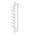
図1は、工場の生産ラインに設置される本発明の一実施の形態の赤外線カメラ特性確認治具の斜視図である。また、図2は、本実施の形態の赤外線カメラ特性確認治具のターゲット部を示す平面図であり、図3は、該赤外線カメラ特性確認治具のターゲット部を示す正面図である。
図1に示すように、本実施の形態の赤外線カメラ特性確認治具は、特性確認を行う赤外線カメラがその前部に搭載された車両1に対し、該車両1の前方に、全体が加温または冷却されて赤外線放射源となるアルミニウム製の背面板2と、車両1側から見て該背面板2の前方に、同じくアルミニウム製で、同一サイズの真円からなる複数の孔(以下ターゲット孔という)が等間隔で設けられた前面板3とが、ターゲット部として配置されている。
【0013】
また、背面板2は、おおよそ横方向の幅が車両1の横幅と同程度で、縦方向の高さが車両1の車種に拘わらずその高さより十分に高く、赤外線カメラが車両1のどこに取り付けられても、高さ方向に対しては十分に対応できる寸法の板状部材で、支柱4a、4bの下方に設けられている。これに対して、前面板3は、背面板2の前方を、支柱4a、4bに沿って上下方向に移動可能に設けられており、制御装置5からの制御により、その高さは例えば地面から背面板2の2倍程度の高さまで移動させることができる。これにより、車両1の車種が変わって赤外線カメラの取付けられた高さが変更されても、背面板2と前面板3とからなるターゲット部の高さを赤外線カメラの高さに調節することができる。
【0014】
更に、背面板2と前面板3について詳細に説明すると、図2に示すように、車両1側から見て背面板2の後方には、ヒータやペルチェ素子等を利用した温度調節器6が設けられており、背面板2の全体を加温または冷却することができる。また、前面板3は、支柱4a、4bにより、背面板2から適度な距離を取って設けられており、また支柱4a、4bを熱伝導率の低い部材とすることにより、背面板2の温度が直接前面板3へ伝わらないようになっている。更に、前面板3を支柱4a、4bの最上部へ移動した際は、前面板3は背面板2の加温または冷却の影響を受けないようになっている。
【0015】
また、図3に示すように、前面板3は、その中央横方向1列に、真円からなる複数のターゲット孔(例えば11個のターゲット孔H1〜H11)が等間隔で設けられており、車両1の方向からは、このターゲット孔H1〜H11を通して背面板2を見ることができる。更に、車両1側から見て前面板3の前面(表面)には、低反射率の起毛紙3aが全面に貼り付けられており、車両1に反射する赤外線や車両1が放射する赤外線が、前面板3に反射して車両1の方向へ戻らないようになっている。
【0016】
これにより、本実施の形態の赤外線カメラ特性確認治具のターゲット部では、背面板2と前面板3とを重ねて配置すると共に背面板2を加温すると、車両1に搭載された赤外線カメラにより、前面板3に設けられたターゲット孔H1〜H11を介して、背面板2の放射する赤外線を、図4に示すようなグレースケール画像として撮影することができる。また、図4に示すグレースケール画像において、ターゲット孔H1〜H11付近を2値化すると、図5に示すような2値化画像を得ることができる。
また、もし背面板2を冷却した場合は、前面板3の放射する赤外線を撮影することになるので、図4とは白黒が反転した2値化画像を撮影することができる。
【0017】
なお、背面板2を加温する場合、背面板2の表面(前面板3側)に赤外線放射率が0.9以上ある紙やカーボン等の材料を貼り付けることで、背面板2からより強い赤外線を放射することができる。従って、強い赤外線放射を必要とする場合は、背面板2に紙やカーボン等の部材を貼り付けて、更に温度調節器6により背面板2を加温すれば良く、また、赤外線カメラ特性確認治具のコストを低く抑えるのであれば、温度調節器6を省略し、背面板2に紙やカーボン等の部材を貼り付けたものを赤外線放射源として用いても良い。
【0018】
次に、本実施の形態の赤外線カメラ特性確認治具を利用した車両搭載赤外線カメラの特性確認手順について説明する。
図6は、本実施の形態の赤外線カメラ特性確認治具を利用した、車両1に搭載された画像処理ユニットによる赤外線カメラの特性確認手順を示すフローチャートである。
図6において、まず、画像処理ユニットは、ステレオ赤外線カメラの出力信号である赤外線画像を取得して(ステップS1)、A/D変換し(ステップS2)、グレースケール画像を画像メモリに格納する(ステップS3)。なお、ここでは、右側の赤外線カメラによりターゲット孔H1〜H11を撮影した右画像が得られ、左側の赤外線カメラによりターゲット孔H1〜H11を撮影した左画像が得られる。
【0019】
ステップS3において図4に示すようなグレースケール画像が得られたら、次に、左右の赤外線カメラ画像を2値化処理、すなわち、輝度閾値ITHより明るい領域を「1」(白)とし、暗い領域を「0」(黒)とする処理を行い、図5に示すような2値化画像を得る(ステップS4)。
次に、得られた2値化画像に写された各ターゲット孔H1〜H11の重心座標を算出する(ステップS5)。
【0020】
そして、理論投影X座標とステップS4で求めた計測重心X座標との差から、投影座標誤差を算出する(ステップS6)。具体的には、実空間位置におけるターゲット孔H1〜H11の画像面内投影座標(理論投影X座標)が、下記(1)式により求められるので、理論投影X座標と計測重心X座標とから、「投影X座標誤差=理論投影X座標−計測重心X座標」を求める。
【数1】
【0021】
更に、図5に示す2値化処理された複数のターゲット孔H1〜H11の各位置について、それぞれ投影X座標誤差を算出し、左右の赤外線カメラ画像それぞれについて、複数のターゲット孔H1〜H11の投影X座標誤差に対応する画像面内投影座標誤差曲線を求める(ステップS7)。具体的には、図7に示すように、x軸に計測重心X座標、y軸に投影X座標誤差をプロットし、直線近似または多項式近似により、複数のターゲット孔H1〜H11の投影X座標誤差に対応する画像面内投影座標誤差曲線を求める。なお、下記(2)式は、図7に示すように、画像面内投影座標誤差曲線を6次多項式で近似した結果である。また、図7に示すαは、ターゲット孔H9の投影座標誤差を示す。
【数2】
【0022】
また、求められた画像面内投影座標誤差曲線は、計測された対象物重心X座標に対する投影X座標誤差を示すものであるが、ここで、レンズ歪はレンズ中心に対して対象であるため、画像面内投影座標誤差曲線をレンズ中心からの距離に対する投影座標誤差として扱っても良い。すなわち、図8(a)に示すように、計測された対象物重心座標を(Xp、Yp)とすると、図8(b)に示すように、図7のx軸に割り当てられた計測重心X座標を、下記(3)式で求められるレンズ中心からの距離Rに置き換えて、レンズ中心からの距離Rに対する投影座標誤差を求めることができる。
【数3】
なお、上述の理論投影X座標と計測重心X座標との差から、画像面内投影座標誤差曲線を求める方法では、上述の(1)式が成立するためには基準となるセンターターゲット孔H6が画像面内の中心にくるようにカメラ取付け位置を調整しなければならないが、工場でのカメラ取付け精度や設備装置の精度からこれを実現するのは困難である。
しかし、図9に示すようなカメラの取付け角(パン角)θを求めることができれば、理論投影座標を求めることが可能である。この場合、実空間位置におけるターゲット孔H1〜H11の画像面内投影座標(理論投影X座標)は下記(4)式により求められる。
【数4】
【0024】
そこで、次に、本実施の形態の赤外線カメラ特性確認治具において、上述の画像面内投影座標誤差曲線を求める別の方法について説明する。
画像面内投影座標誤差曲線を求める別の方法では、センターターゲット孔(H6)の位置を基準にして測定したセンターターゲット孔とその他の各ターゲット孔までの計測長と理論長との差から、画像面内投影座標誤差曲線を求める。
具体的には、図6に示すフローチャートのステップS3において、グレースケール画像が得られたら、次に、左右の赤外線カメラ画像を2値化処理、すなわち、輝度閾値ITHより明るい領域を「1」(白)とし、暗い領域を「0」(黒)とする処理を行い2値化画像を得る。
次に、得られた2値化画像に写された各ターゲット孔H1〜H11の重心座標を算出する。
【0025】
そして、図10に示す実空間上のセンターターゲット孔(H6)からその他の各ターゲット孔までの画像面内長さ(理論長:LR1〜LR11)を、下記(5)式に基づいて求め、H6と各孔までの計測長(LJ1〜LJ11)とH6と各孔までの理論長(LR1〜LR11)とから、「投影X座標誤差=H6と各孔までの計測長−H6と各孔までの理論長」を求める。
【数5】
【0026】
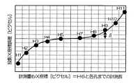
更に、図5に示す2値化処理された複数のターゲット孔H1〜H11の各位置について、それぞれ下記表1のように投影X座標誤差を算出し、複数のターゲット孔の投影X座標誤差に対応する画像面内投影座標誤差曲線を求める。具体的には、図11に示すように、x軸に計測重心X座標=H6と各孔までの計測長、y軸に投影X座標誤差をプロットし、直線近似または多項式近似により、複数のターゲット孔H1〜H11の投影X座標誤差に対応する画像面内投影座標誤差曲線を求める。なお、図11に示す画像面内投影座標誤差曲線を6次多項式で近似した場合、前述の(2)式を得る。また、図11に示すβは、センターターゲット孔H6からターゲット孔H9までの投影X座標誤差(=LJ9−LR9)を示す。
【0027】
【表1】
従って、センターターゲット孔(H6)の位置を基準にして測定したセンターターゲット孔とその他の各ターゲット孔までの計測長と理論長との差から、画像面内投影座標誤差曲線を求める方法では、カメラのパン角θが発生しても、センターターゲット孔からその他の各ターゲット孔までの距離は不変なため、センターターゲット孔と各ターゲット孔までの計測長と理論長との差から、画像面内投影座標誤差曲線を求めることが可能である。
【0029】
以上説明したように、本実施の形態の赤外線カメラ特性確認治具は、複数の孔を一列に備えた前面板3の後方に、該前面板3と平行になるように赤外線放射源となる背面板2を配置し、温度調節器6により加温した背面板2から、前面板3より強い赤外線を放射することにより、前面板3の孔を通過した赤外線によって、一様に並んだ複数の赤外線放射部を作成することができる。なお、温度調節器6により背面板2を冷却した場合は、背面板2より前面板3の方が強い赤外線を放射するので、赤外線カメラで撮影した画像の白黒が反転する。
【0030】
また、前面板3に赤外線反射を抑制する加工を施すことにより、背面板2から放射された赤外線が特性確認を行う赤外線カメラの搭載された車両1に反射し、更に反射した赤外線が前面板3に再反射し、赤外線カメラの特性確認に影響を与えることを抑制することができる。
更に、背面板2に、紙やカーボン等の赤外線放射率の高い材料を貼付することにより、該材料表面から前面板3より強い赤外線を放射させることで、温度調節器6を省略し、温度調節器6による背面板2の加温をやめて、赤外線カメラ特性確認治具のコストを下げることができる。
【0031】
また、背面板2の前方を上下に移動可能なように前面板3を設けることで、車両1の車種が変わって赤外線カメラの取付けられた高さが変更されても、前面板3の高さを赤外線カメラの高さに調節することができる。また、前面板3を背面板2の前方から移動して背面板2との距離を離し、不用意に前面板3が加温または冷却されて、不要な赤外線を放射する、または必要な赤外線を放射しないことを防止することができる。
【0032】
従って、特性確認を行う赤外線カメラで、赤外線カメラ特性確認治具により作成された一様に並ぶ複数の赤外線放射部を撮影し、該赤外線放射部の実空間上の位置座標と該赤外線放射部の画像上の投影座標との比較から、この赤外線カメラに使用されているレンズの全方向のレンズ歪や焦点距離のバラツキを、画像面内投影座標誤差曲線として求めることができるという効果が得られる。
【0033】
【発明の効果】
以上の如く、請求項1に記載の赤外線カメラ特性確認治具によれば、複数の孔を一列に備えたカバープレートの後方に放射源を配置し、該放射源からカバープレートより強い赤外線を放射することにより、カバープレートの孔を通過した赤外線によって、一様に並んだ複数の赤外線放射部を作成することができる。また、放射源からカバープレートより弱い赤外線を放射することにより、カバープレートの孔以外の部分から放射された赤外線によって、一様に並んだ複数の赤外線非放射部を作成することができる。
従って、発生形状が明確な複数の赤外線放射部、あるいは、赤外線カメラで撮影した場合に赤外線放射部とは写り方が逆になる赤外線非放射部を利用して、測定精度の高い赤外線カメラの特性確認を行うことができるという効果が得られる。
また、カバープレートに赤外線反射を抑制する加工を施すことにより、放射源から放射された赤外線が特性確認を行う赤外線カメラが搭載された車両に反射し、更に反射した赤外線がカバープレートに再反射することを抑制することができる。
従って、車両に反射した赤外線が再度カバープレートに反射することによる赤外線放射部または赤外線非放射部の発生形状の乱れを防止し、測定精度の高い赤外線カメラの特性確認を行うことができるという効果が得られる。
【0034】
請求項2に記載の赤外線カメラ特性確認治具によれば、カバープレートの高さを被測定物の高さに調節することができる。また、カバープレートを放射源の前方から移動して、不用意にカバープレートが加温または冷却され、不要な赤外線を放射する、または必要な赤外線を放射しないことを防止することができる。
従って、例えば車両の製造ライン等で、車種の違いによる被測定物の高さの違いに対応すると共に、間欠的に実行する赤外線カメラの特性確認に対応し、必要な時だけカバープレートを放射源の前方に配置して一様に並んだ複数の赤外線放射部または赤外線非放射部を作成することで、いつでも測定精度の高い赤外線カメラの特性確認を行うことができるという効果が得られる。
【0035】
請求項3に記載の赤外線カメラ特性確認治具によれば、複数の孔を一列に備えたカバープレートの後方に放射源を配置し、該放射源からカバープレートより強い赤外線を放射することにより、カバープレートの孔を通過した赤外線によって、一様に並んだ複数の赤外線放射部を作成することができる。また、放射源からカバープレートより弱い赤外線を放射することにより、カバープレートの孔以外の部分から放射された赤外線によって、一様に並んだ複数の赤外線非放射部を作成することができる。
従って、発生形状が明確な複数の赤外線放射部、あるいは、赤外線カメラで撮影した場合に赤外線放射部とは写り方が逆になる赤外線非放射部を利用して、測定精度の高い赤外線カメラの特性確認を行うことができるという効果が得られる。
また、カバープレートの高さを被測定物の高さに調節することができる。また、カバープレートを放射源の前方から移動して、不用意にカバープレートが加温または冷却され、不要な赤外線を放射する、または必要な赤外線を放射しないことを防止することができる。
従って、例えば車両の製造ライン等で、車種の違いによる被測定物の高さの違いに対応すると共に、間欠的に実行する赤外線カメラの特性確認に対応し、必要な時だけカバープレートを放射源の前方に配置して一様に並んだ複数の赤外線放射部または赤外線非放射部を作成することで、いつでも測定精度の高い赤外線カメラの特性確認を行うことができるという効果が得られる。
【0036】
請求項4に記載の赤外線カメラ特性確認治具によれば、熱源によって金属を加温または冷却して、該金属板表面から一様に赤外線を放射させることで、正確に並んだ赤外線放射部または赤外線非放射部を容易に作成することができる。
従って、熱源を制御することで、容易に赤外線カメラによって放射源を撮影した際の画像のコントラストを大きくすることができ、測定精度の高い赤外線カメラの特性確認を行うことができるという効果が得られる。
【0037】
請求項5に記載の赤外線カメラ特性確認治具によれば、金属板にカバープレートより赤外線放射率の高い材料を貼付して、該材料表面から一様に赤外線を放射させることで、正確に並んだ赤外線放射部を安価に作成することができる。
従って、赤外線カメラ特性確認治具のコストを下げることができるという効果が得られる。
【図面の簡単な説明】
【図1】 本発明の一実施の形態の赤外線カメラ特性確認治具の斜視図である。
【図2】 同実施の形態の赤外線カメラ特性確認治具のターゲット部を示す平面図である。
【図3】 同実施の形態の赤外線カメラ特性確認治具のターゲット部を示す正面図である。
【図4】 同実施の形態の赤外線カメラ特性確認治具のターゲット部を車両に搭載された赤外線カメラで撮影した場合のグレースケール画像を示す図である。
【図5】 同実施の形態の赤外線カメラ特性確認治具のターゲット部のグレースケール画像を2値化処理した2値化画像を示す図である。
【図6】 同実施の形態の赤外線カメラ特性確認治具を利用した、車両に搭載された画像処理ユニットによる赤外線カメラの特性確認手順を示すフローチャートである。
【図7】 同実施の形態の赤外線カメラ特性確認治具を利用して取得した画像面内投影座標誤差曲線を示す図である。
【図8】 同実施の形態の赤外線カメラ特性確認治具を利用して取得した画像面内投影座標誤差曲線を、レンズ中心からの距離Rに対する投影座標誤差曲線として示す図である。
【図9】 車両に搭載されたカメラの取付け角(パン角θ)を示す図である。
【図10】 同実施の形態の赤外線カメラ特性確認治具のターゲット部を車両に搭載された赤外線カメラで撮影した場合のグレースケール画像を示す図である。
【図11】 同実施の形態の赤外線カメラ特性確認治具を利用して、別な方法により取得した画像面内投影座標誤差曲線を示す図である。
【符号の説明】
1 車両
2 背面板(放射源の金属板)
3 前面板(カバープレート)
3a 起毛紙
4a、4b 支柱
5 制御装置
6 温度調節器(放射源の熱源)
H1〜H11 ターゲット孔[0001]
BACKGROUND OF THE INVENTION
The present invention relates to an infrared camera characteristic confirmation jig for confirming characteristics of an infrared camera for distance measurement of an object mounted on a vehicle.
[0002]
[Prior art]
Conventionally, there is a three-dimensional measurement technique for obtaining the distance to an object using the parallax of a pair of object images photographed by two cameras (stereo cameras). In such a technique, an image correction apparatus is required in order to correct a positional deviation due to lens distortion and variations in focal length and to obtain an accurate object distance. Such an image correction apparatus for a stereo camera previously captures a specific correction amount measurement imaging pattern such as a regular lattice pattern with both cameras of the stereo camera in advance, and coordinates for each pixel of the captured image of each camera. Calculate the correction amount. The result is held as a coordinate correction table, and the data stored in the image memory is corrected for each pixel by the correction amount of the coordinate correction table, thereby obtaining accurate image data. At this time, the correction of the positional deviation due to the lens distortion and the variation in the focal length is performed only in the vertical direction (see, for example, Patent Document 1).
[0003]
[Patent Document 1]
Japanese Patent Laid-Open No. 11-325889
[0004]
[Problems to be solved by the invention]
By the way, as an application example of the three-dimensional measurement technique using the stereo camera as described above, there is one in which an obstacle existing in front of the vehicle is detected earlier than the driver of the vehicle and this is notified to the driver. In this case, an infrared camera capable of photographing infrared rays is usually used as the stereo camera so that it can cope with night driving.
However, in the prior art, in order to perform positional deviation correction due to lens distortion and variations in focal length, a specific correction amount measurement imaging pattern such as a regular grid pattern is simultaneously captured by both cameras of the stereo camera, While it is necessary to calculate the coordinate correction amount for each pixel for the captured image of each camera, when using an infrared camera as a stereo camera, it is possible to realize a regular lattice pattern that can be accurately captured by the infrared camera. There was a problem that it was difficult.
[0005]
The present invention has been made in view of the above problems, and provides an infrared camera characteristic confirmation jig capable of easily measuring an object projection coordinate error occurring in both a horizontal direction and a vertical direction of an image. Objective.
[0006]
[Means for Solving the Problems]
In order to solve the above problems, an infrared camera characteristic confirmation jig according to the invention of claim 1 is an infrared camera characteristic confirmation jig for confirming the characteristics of an infrared camera using an infrared camera as a measurement object. A cover plate (for example, the
[0007]
The infrared camera characteristic confirmation jig having the above-described configuration is such that a radiation source is arranged behind a cover plate having a plurality of holes in a row so as to be parallel to the cover plate. By radiating strong infrared rays, it is possible to create a plurality of infrared radiation portions arranged uniformly by the infrared rays that have passed through the holes of the cover plate. In addition, by emitting weak infrared rays from the radiation source from the radiation source, it is possible to create a plurality of uniformly arranged infrared non-radiation parts due to the difference from the infrared rays emitted from portions other than the holes of the cover plate. .
In addition, by processing the cover plate to suppress infrared reflection, the infrared light emitted from the radiation source is reflected on the vehicle equipped with the infrared camera that confirms the characteristics, and the reflected infrared light is reflected again on the cover plate. Can be suppressed.
[0008]
The infrared camera characteristic confirmation jig according to the invention of claim 2 is the infrared camera characteristic confirmation jig according to claim 1,The cover plate is provided so as to be movable up and down in front of the radiation source when viewed from the side of the object to be measured, from a position where the characteristics of the object to be measured can be measured to a position sufficiently higher than the radiation source. TheIt is characterized by that.
The infrared camera characteristic confirmation jig with the above configuration isEven if the height of the object to be measured is changed, the height of the cover plate can be adjusted to the height of the object to be measured. Also, by moving the cover plate from the front of the radiation source and moving it away from the radiation source, the cover plate is inadvertently heated or cooled to emit unnecessary infrared rays or not emit necessary infrared rays. Preventcan do.
[0009]
The infrared camera characteristic confirmation jig according to the invention of
The infrared camera characteristic confirmation jig with the above configuration isA radiation source is arranged behind the cover plate having a plurality of holes in a row so as to be parallel to the cover plate, and the infrared rays emitted from the radiation source are stronger than the cover plate, thereby passing through the holes of the cover plate. A plurality of uniformly arranged infrared radiation portions can be created by the infrared rays. Also, by emitting a weaker infrared ray from the radiation source than the cover plate, a plurality of uniformly arranged infrared non-radiating parts are formed by the difference from the infrared ray emitted from the part other than the hole of the cover plate.Can be created.
Moreover, even if the height of the object to be measured is changed, the height of the cover plate can be adjusted to the height of the object to be measured. Also, by moving the cover plate from the front of the radiation source and moving it away from the radiation source, the cover plate is inadvertently heated or cooled to emit unnecessary infrared rays or not emit necessary infrared rays. This can be prevented.
[0010]
The infrared camera property confirmation jig according to
The infrared camera characteristic confirmation jig with the above configuration isBy heating or cooling the metal with a heat source, infrared rays are uniformly emitted from the surface of the metal plate, and the infrared rays are passed through the holes of the cover plate, thereby giving a difference in the amount of infrared rays with the cover plate. Easily create infrared radiating parts or non-infrared radiating partscan do.
[0011]
An infrared camera characteristic confirmation jig according to a fifth aspect of the present invention is the first aspect of the present invention.3In the infrared camera characteristic confirmation jig according to any one ofThe radiation source is formed by attaching a material (for example, paper or carbon of the embodiment) having a higher infrared emissivity than the cover plate to a metal plate (for example, the back plate 2 of the embodiment).It is characterized by that.
The infrared camera characteristic confirmation jig with the above configuration isBy attaching a material with higher infrared emissivity than the cover plate to the metal plate, the infrared rays are emitted uniformly from the surface of the material, and the infrared rays are accurately arranged by passing the infrared rays through the holes in the cover plate. Create cheaplybe able to.
[0012]
DETAILED DESCRIPTION OF THE INVENTION
Embodiments of the present invention will be described below with reference to the drawings.
FIG. 1 is a perspective view of an infrared camera characteristic confirmation jig according to an embodiment of the present invention installed in a production line of a factory. FIG. 2 is a plan view showing a target portion of the infrared camera characteristic confirmation jig according to the present embodiment, and FIG. 3 is a front view showing the target part of the infrared camera characteristic confirmation jig.
As shown in FIG. 1, the infrared camera characteristic confirmation jig according to the present embodiment is entirely heated in front of the vehicle 1 with respect to the vehicle 1 on which the infrared camera for performing characteristic confirmation is mounted. Alternatively, an aluminum back plate 2 to be cooled and used as an infrared radiation source, and a plurality of holes made of perfect circles of the same size (hereinafter referred to as target holes) in front of the back plate 2 when viewed from the vehicle 1 side. And the
[0013]
Further, the rear plate 2 has a width approximately equal to the width of the vehicle 1 and a height in the vertical direction that is sufficiently higher than the height regardless of the type of the vehicle 1. Even if it is, it is a plate-like member having a dimension that can sufficiently cope with the height direction, and is provided below the
[0014]
Further, the back plate 2 and the
[0015]
Moreover, as shown in FIG. 3, the
[0016]
Thereby, in the target part of the infrared camera characteristic confirmation jig of the present embodiment, when the back plate 2 and the
In addition, if the back plate 2 is cooled, the infrared rays emitted from the
[0017]
When the back plate 2 is heated, it is stronger than the back plate 2 by sticking a material such as paper or carbon having an infrared emissivity of 0.9 or more to the surface of the back plate 2 (
[0018]
Next, the characteristic confirmation procedure of the vehicle-mounted infrared camera using the infrared camera characteristic confirmation jig of the present embodiment will be described.
FIG. 6 is a flowchart showing a procedure for confirming the characteristics of the infrared camera by the image processing unit mounted on the vehicle 1 using the infrared camera characteristics confirmation jig according to the present embodiment.
In FIG. 6, first, the image processing unit acquires an infrared image that is an output signal of the stereo infrared camera (step S1), performs A / D conversion (step S2), and stores the grayscale image in the image memory (step S2). Step S3). Here, a right image obtained by photographing the target holes H1 to H11 is obtained by the right infrared camera, and a left image obtained by photographing the target holes H1 to H11 is obtained by the left infrared camera.
[0019]
If a grayscale image as shown in FIG. 4 is obtained in step S3, then the left and right infrared camera images are binarized, that is, the area brighter than the luminance threshold ITH is set to “1” (white), and the dark area Is set to “0” (black) to obtain a binary image as shown in FIG. 5 (step S4).
Next, the center-of-gravity coordinates of the target holes H1 to H11 shown in the obtained binarized image are calculated (step S5).
[0020]
Then, the projection coordinate error is calculated from the difference between the theoretical projection X coordinate and the measured gravity center X coordinate obtained in step S4 (step S6). Specifically, since the in-plane projection coordinates (theoretical projection X coordinate) of the target holes H1 to H11 at the real space position are obtained by the following equation (1), from the theoretical projection X coordinate and the measured gravity center X coordinate, “Projection X coordinate error = theoretical projection X coordinate−measured gravity center X coordinate” is obtained.
[Expression 1]
[0021]
Further, projection X coordinate errors are calculated for the respective positions of the plurality of binarized target holes H1 to H11 shown in FIG. 5, and the projections of the plurality of target holes H1 to H11 are obtained for the left and right infrared camera images, respectively. An in-plane projection coordinate error curve corresponding to the X coordinate error is obtained (step S7). Specifically, as shown in FIG. 7, the measured gravity center X coordinate is plotted on the x axis and the projected X coordinate error is plotted on the y axis, and the projected X coordinate errors of the plurality of target holes H1 to H11 are obtained by linear approximation or polynomial approximation. An in-plane projected coordinate error curve corresponding to is obtained. The following equation (2) is the result of approximating the in-plane projected coordinate error curve with a sixth-order polynomial as shown in FIG. Moreover, (alpha) shown in FIG. 7 shows the projection coordinate error of the target hole H9.
[Expression 2]
[0022]
Further, the obtained in-plane projection coordinate error curve shows a projection X coordinate error with respect to the measured object center of gravity X coordinate, but here, since lens distortion is a target with respect to the lens center, The in-plane projection coordinate error curve may be treated as a projection coordinate error with respect to the distance from the lens center. That is, as shown in FIG. 8A, if the measured object center-of-gravity coordinates are (Xp, Yp), as shown in FIG. 8B, the measured center-of-gravity X assigned to the x-axis in FIG. By replacing the coordinates with the distance R from the lens center obtained by the following equation (3), a projection coordinate error with respect to the distance R from the lens center can be obtained.
[Equation 3]
In the method of obtaining the in-plane projection coordinate error curve from the difference between the theoretical projection X coordinate and the measured gravity center X coordinate, the center target hole H serving as a reference is required in order to satisfy the above equation (1).6However, it is difficult to achieve this because of the camera mounting accuracy in the factory and the accuracy of the equipment.
However, if the camera mounting angle (pan angle) θ as shown in FIG. 9 can be obtained, the theoretical projection coordinates can be obtained. In this case, the in-image projection coordinates (theoretical projection X coordinates) of the target holes H1 to H11 at the real space positions are obtained by the following equation (4).
[Expression 4]
[0024]
Therefore, another method for obtaining the above-mentioned in-image projection coordinate error curve in the infrared camera characteristic confirmation jig according to the present embodiment will be described next.
In another method for obtaining an in-plane projected coordinate error curve, an image is calculated from the difference between the measured length and the theoretical length from the center target hole measured on the basis of the position of the center target hole (H6) and the other target holes. An in-plane projection coordinate error curve is obtained.
Specifically, if a grayscale image is obtained in step S3 of the flowchart shown in FIG. 6, then the left and right infrared camera images are binarized, that is, an area brighter than the luminance threshold ITH is set to “1” ( White) and a dark area is set to “0” (black) to obtain a binary image.
Next, the center-of-gravity coordinates of the target holes H1 to H11 shown in the obtained binarized image are calculated.
[0025]
Then, the image in-plane length (theoretical length: LR1 to LR11) from the center target hole (H6) in the real space shown in FIG. 10 to the other target holes is obtained based on the following equation (5), and H6 From the measured length to each hole (LJ1 to LJ11), H6 and the theoretical length to each hole (LR1 to LR11), "projection X coordinate error = H6 and measured length to each hole-H6 and to each hole. Find the theoretical head.
[Equation 5]
[0026]
Further, for each position of the plurality of target holes H1 to H11 subjected to binarization processing shown in FIG. 5, a projection X coordinate error is calculated as shown in Table 1 below, and corresponding to the projection X coordinate errors of the plurality of target holes. An image in-plane projected coordinate error curve is obtained. Specifically, as shown in FIG. 11, the measurement center of gravity X coordinate = H6 and the measurement length to each hole are plotted on the x axis, and the projection X coordinate error is plotted on the y axis, and a plurality of targets are obtained by linear approximation or polynomial approximation. An in-plane projected coordinate error curve corresponding to the projected X coordinate errors of the holes H1 to H11 is obtained. When the in-plane projection coordinate error curve shown in FIG. 11 is approximated by a sixth-order polynomial, the above-described equation (2) is obtained. Further, β shown in FIG. 11 represents a projection X coordinate error (= LJ9−LR9) from the center target hole H6 to the target hole H9.
[0027]
[Table 1]
Therefore, in the method of obtaining an in-plane projection coordinate error curve from the difference between the measured length and the theoretical length from the center target hole measured with reference to the position of the center target hole (H6) and the other target holes, the camera Since the distance from the center target hole to each of the other target holes is not changed even if the pan angle θ is generated, the in-plane projection is performed based on the difference between the measured length and the theoretical length from the center target hole to each target hole. A coordinate error curve can be obtained.
[0029]
As described above, the infrared camera characteristic confirmation jig according to the present embodiment has a back which becomes an infrared radiation source so as to be parallel to the
[0030]
Further, by processing the
Further, by sticking a material having a high infrared emissivity such as paper or carbon to the back plate 2, the infrared light stronger than the
[0031]
In addition, by providing the
[0032]
Therefore, with an infrared camera that performs characteristic confirmation, a plurality of uniformly arranged infrared radiation parts created by the infrared camera characteristic confirmation jig are photographed, and the position coordinates of the infrared radiation part in real space and the infrared radiation part From the comparison with the projected coordinates on the image, there is an effect that the lens distortion in all directions and the variation in the focal length of the lens used in the infrared camera can be obtained as an in-plane projected coordinate error curve.
[0033]
【The invention's effect】
As described above, according to the infrared camera characteristic confirmation jig of the first aspect, the radiation source is arranged behind the cover plate having a plurality of holes in a row, and infrared rays stronger than the cover plate are emitted from the radiation source. By doing so, a plurality of infrared radiation portions arranged uniformly can be created by the infrared rays that have passed through the holes of the cover plate. Moreover, by emitting infrared rays weaker than the cover plate from the radiation source, it is possible to create a plurality of infrared non-radiating portions that are uniformly arranged by infrared rays emitted from portions other than the holes of the cover plate.
Therefore, the characteristics of an infrared camera with high measurement accuracy can be obtained by using multiple infrared emitters with a clear generation shape, or using an infrared non-radiator that is opposite to the infrared emitter when taken with an infrared camera. The effect that confirmation can be performed is obtained.
In addition, by processing the cover plate to suppress infrared reflection, the infrared light emitted from the radiation source is reflected on the vehicle on which the infrared camera for confirming the characteristics is mounted, and the reflected infrared light is reflected again on the cover plate. This can be suppressed.
Therefore, it is possible to prevent disturbance of the shape of the infrared radiation part or infrared non-radiation part due to the infrared light reflected on the vehicle being reflected again on the cover plate, and to confirm the characteristics of the infrared camera with high measurement accuracy. can get.
[0034]
According to the infrared camera characteristic confirmation jig of claim 2,The height of the cover plate can be adjusted to the height of the object to be measured. In addition, the cover plate is moved from the front of the radiation source to prevent the cover plate from being inadvertently heated or cooled to emit unnecessary infrared rays or emit necessary infrared rays.can do.
Therefore,For example, in response to differences in the height of the object to be measured due to differences in the type of vehicle on the vehicle production line, etc., it is also possible to check the characteristics of the infrared camera that is executed intermittently. It is possible to check the characteristics of an infrared camera with high measurement accuracy at any time by creating multiple infrared emitters or non-infrared emitters arranged in a uniform arrayThe effect is obtained.
[0035]
According to the infrared camera characteristic confirmation jig according to
Therefore,Check the characteristics of an infrared camera with high measurement accuracy by using multiple infrared emitters with a clear shape, or an infrared non-radiator that is the opposite of the infrared emitter when taken with an infrared camera. DoThe effect that it can be obtained.
Further, the height of the cover plate can be adjusted to the height of the object to be measured. In addition, the cover plate can be moved from the front of the radiation source to prevent the cover plate from being inadvertently heated or cooled to emit unnecessary infrared rays or not emit necessary infrared rays.
Therefore, for example, in the production line of a vehicle, it corresponds to the difference in the height of the object to be measured due to the difference in the vehicle type, and corresponds to the confirmation of the characteristics of the infrared camera that is executed intermittently. By producing a plurality of infrared radiation portions or infrared non-radiation portions that are arranged in front of and uniformly arranged, it is possible to check the characteristics of the infrared camera with high measurement accuracy at any time.
[0036]
According to the infrared camera characteristic confirmation jig of
Therefore,By controlling the heat source, you can easily increase the contrast of the image when shooting the radiation source with an infrared camera,An effect is obtained that the characteristics of the infrared camera with high measurement accuracy can be confirmed.
[0037]
According to the infrared camera characteristic confirmation jig of
Therefore,Reduce the cost of infrared camera characteristics confirmation jigThe effect that it can be obtained.
[Brief description of the drawings]
FIG. 1 is a perspective view of an infrared camera characteristic confirmation jig according to an embodiment of the present invention.
FIG. 2 is a plan view showing a target portion of the infrared camera characteristic confirmation jig according to the embodiment;
FIG. 3 is a front view showing a target portion of the infrared camera characteristic confirmation jig according to the embodiment;
FIG. 4 is a diagram showing a grayscale image when the target portion of the infrared camera characteristic confirmation jig according to the embodiment is photographed by an infrared camera mounted on a vehicle.
FIG. 5 is a view showing a binarized image obtained by binarizing a grayscale image of a target portion of the infrared camera characteristic confirmation jig according to the embodiment;
FIG. 6 is a flowchart showing a procedure for checking the characteristics of an infrared camera using an image processing unit mounted on a vehicle, using the infrared camera characteristics checking jig of the embodiment.
FIG. 7 is a view showing an in-plane projection coordinate error curve obtained using the infrared camera characteristic confirmation jig of the embodiment.
FIG. 8 is a diagram illustrating an in-plane projection coordinate error curve acquired using the infrared camera characteristic confirmation jig according to the embodiment as a projection coordinate error curve with respect to a distance R from the lens center;
FIG. 9 is a diagram showing a mounting angle (pan angle θ) of a camera mounted on a vehicle.
FIG. 10 is a diagram showing a grayscale image when the target portion of the infrared camera characteristic confirmation jig according to the embodiment is photographed by an infrared camera mounted on a vehicle.
11 is a diagram showing an in-plane projection coordinate error curve obtained by another method using the infrared camera characteristic confirmation jig of the embodiment. FIG.
[Explanation of symbols]
1 vehicle
2 Back plate (metal plate of radiation source)
3 Front plate (cover plate)
3a Brushed paper
4a, 4b Prop
5 Control device
6 Temperature controller (heat source of radiation source)
H1-H11 target hole
Claims (5)
Translated fromJapanese複数の孔を一列に備えたカバープレートと、
前記被測定物の側から見て前記カバープレートの後方に、前記カバープレートと並行になるように配置されると共に、前記カバープレートとは異なる量の赤外線を放射する放射源とを備え、
前記カバープレートは、赤外線反射を抑制する加工が施されていることを特徴とする赤外線カメラ特性確認治具。An infrared camera characteristic confirmation jig for confirming the characteristics of the infrared camera, using the infrared camera as a measurement object,
A cover plate with a plurality of holes in a row;
A radiation source that radiates an amount of infrared rays different from that of the cover plate, arranged behind the cover plate as viewed from the object to be measured and in parallel with the cover plate;
An infrared camera characteristic confirmation jig, wherein the cover plate is processed to suppress infrared reflection .
複数の孔を一列に備えたカバープレートと、
前記被測定物の側から見て前記カバープレートの後方に、前記カバープレートと並行になるように配置されると共に、前記カバープレートとは異なる量の赤外線を放射する放射源とを備え、
前記カバープレートが、前記被測定物の側から見て前記放射源の前方を、上下に、前記被測定物の特性を測定可能な位置から、前記放射源より十分高い位置まで移動可能に設けられたことを特徴とする赤外線カメラ特性確認治具。An infrared camera characteristic confirmation jig for confirming the characteristics of the infrared camera, using the infrared camera as a measurement object,
A cover plate with a plurality of holes in a row;
A radiation source that radiates an amount of infrared rays different from that of the cover plate, arranged behind the cover plate as viewed from the object to be measured and in parallel with the cover plate;
The cover plate is provided so as to be movable up and down in front of the radiation source when viewed from the side of the object to be measured, from a position where the characteristics of the object to be measured can be measured to a position sufficiently higher than the radiation source. infrared camera characterizationtool, characterized in that the.
Priority Applications (3)
| Application Number | Priority Date | Filing Date | Title |
|---|---|---|---|
| JP2002290234AJP3902109B2 (en) | 2002-10-02 | 2002-10-02 | Infrared camera characteristics confirmation jig |
| US10/675,348US7418127B2 (en) | 2002-10-02 | 2003-09-30 | Apparatus for testing infrared camera |
| US12/082,153US8077909B2 (en) | 2002-10-02 | 2008-04-09 | Apparatus and method for testing infrared camera |
Applications Claiming Priority (1)
| Application Number | Priority Date | Filing Date | Title |
|---|---|---|---|
| JP2002290234AJP3902109B2 (en) | 2002-10-02 | 2002-10-02 | Infrared camera characteristics confirmation jig |
Publications (2)
| Publication Number | Publication Date |
|---|---|
| JP2004128887A JP2004128887A (en) | 2004-04-22 |
| JP3902109B2true JP3902109B2 (en) | 2007-04-04 |
Family
ID=32040656
Family Applications (1)
| Application Number | Title | Priority Date | Filing Date |
|---|---|---|---|
| JP2002290234AExpired - Fee RelatedJP3902109B2 (en) | 2002-10-02 | 2002-10-02 | Infrared camera characteristics confirmation jig |
Country Status (2)
| Country | Link |
|---|---|
| US (2) | US7418127B2 (en) |
| JP (1) | JP3902109B2 (en) |
Families Citing this family (31)
| Publication number | Priority date | Publication date | Assignee | Title |
|---|---|---|---|---|
| JP3902109B2 (en)* | 2002-10-02 | 2007-04-04 | 本田技研工業株式会社 | Infrared camera characteristics confirmation jig |
| KR100543709B1 (en)* | 2003-12-23 | 2006-01-20 | 삼성전자주식회사 | Method of using rotational movement amount of moving object and computer readable recording medium storing device and computer program |
| CA2505715A1 (en)* | 2004-05-03 | 2005-11-03 | Her Majesty In Right Of Canada As Represented By The Minister Of National Defence | Volumetric sensor for mobile robotics |
| JP4461091B2 (en) | 2004-11-30 | 2010-05-12 | 本田技研工業株式会社 | Position detection apparatus and correction method thereof |
| JP4032052B2 (en) | 2004-11-30 | 2008-01-16 | 本田技研工業株式会社 | Position detection apparatus and correction method thereof |
| US7599521B2 (en) | 2004-11-30 | 2009-10-06 | Honda Motor Co., Ltd. | Vehicle vicinity monitoring apparatus |
| US7590263B2 (en) | 2004-11-30 | 2009-09-15 | Honda Motor Co., Ltd. | Vehicle vicinity monitoring apparatus |
| JP4224449B2 (en) | 2004-11-30 | 2009-02-12 | 本田技研工業株式会社 | Image extraction device |
| JP2008537190A (en)* | 2005-01-07 | 2008-09-11 | ジェスチャー テック,インコーポレイテッド | Generation of three-dimensional image of object by irradiating with infrared pattern |
| DE102006038423A1 (en)* | 2006-08-17 | 2008-02-21 | Bayerische Motoren Werke Ag | Device for calibrating an optical camera and / or an infrared camera |
| US8254665B2 (en)* | 2006-08-22 | 2012-08-28 | Munro Design & Technologies, Llc | Systems for capturing three-dimensional one or more images and methods thereof |
| JP4440341B2 (en)* | 2008-05-19 | 2010-03-24 | パナソニック株式会社 | Calibration method, calibration apparatus, and calibration system including the apparatus |
| JP5020894B2 (en)* | 2008-06-10 | 2012-09-05 | キヤノン株式会社 | Image processing apparatus, control method, and program |
| EP2254091B1 (en)* | 2009-05-19 | 2020-03-25 | Veoneer Sweden AB | Vision system and method for a motor vehicle |
| DE102010023108B4 (en)* | 2009-06-04 | 2019-12-05 | Sypro Optics Gmbh | Projector with automatic focusing and imaging process |
| KR101129326B1 (en)* | 2010-06-16 | 2012-03-27 | 허성용 | Alignment apparatus of light axis for the image and Method thereof |
| JP5567441B2 (en)* | 2010-09-30 | 2014-08-06 | 本田技研工業株式会社 | Optical axis inspection method and optical axis inspection apparatus for vehicle-mounted camera |
| CN102636336B (en)* | 2012-04-19 | 2014-10-08 | 北京理工大学 | Method for testing operating distance of active near-infrared camera based on equivalent illumination and MRC (Minimum Resolvable Contrast) |
| CN102645321B (en)* | 2012-04-19 | 2014-09-10 | 公安部第一研究所 | Active near-infrared camera operating distance evaluation system based equivalent illumination |
| CN102661851B (en)* | 2012-04-19 | 2015-04-22 | 北京理工大学 | Active near infrared camera operating distance evaluation method based on equivalent illumination |
| US9451247B2 (en) | 2013-11-25 | 2016-09-20 | Ul Llc | Camera test apparatus |
| CN103837326B (en)* | 2014-03-14 | 2016-05-11 | 北京理工大学 | Spliced infrared/the infrared adjustment method of microwave beam synthesizer |
| KR101426314B1 (en)* | 2014-04-24 | 2014-08-06 | (주)코어센스 | Jig for synthesizing image of color camera and thermal camera |
| WO2017056473A1 (en)* | 2015-09-29 | 2017-04-06 | 日本電気株式会社 | Camera calibration board, camera calibration device, camera calibration method, and program-recording medium for camera calibration |
| WO2019087253A1 (en)* | 2017-10-30 | 2019-05-09 | オリンパス株式会社 | Stereo camera calibration method |
| JP7127656B2 (en)* | 2018-01-10 | 2022-08-30 | ソニーグループ株式会社 | CALIBRATION DEVICE, CALIBRATION METHOD AND CALIBRATION CHART DEVICE |
| CN208298251U (en) | 2018-04-17 | 2018-12-28 | 深圳市道通科技股份有限公司 | The caliberating device and system of vehicle-mounted camera |
| CN108335334B (en)* | 2018-04-17 | 2024-04-26 | 深圳市道通科技股份有限公司 | Calibration device, system and method for vehicle-mounted camera |
| JP7356213B2 (en)* | 2018-08-24 | 2023-10-04 | セイコーNpc株式会社 | Heat source for angle of view measurement and angle of view measurement system |
| CN110809154A (en)* | 2019-11-22 | 2020-02-18 | 江苏东方赛光电有限公司 | Image verification system for infrared detector |
| CN114205576A (en)* | 2020-09-02 | 2022-03-18 | 晋城三赢精密电子有限公司 | Camera detection device |
Family Cites Families (13)
| Publication number | Priority date | Publication date | Assignee | Title |
|---|---|---|---|---|
| US3444378A (en)* | 1965-05-13 | 1969-05-13 | Picker Corp | X-ray timing device using a light-conducting paddle with spaced light-admitting holes for uninterrupted light transmission to a detector |
| US4780613A (en)* | 1986-09-22 | 1988-10-25 | Spectral Sciences, Inc. | Infrared species specific emission source |
| US5033015A (en)* | 1988-08-12 | 1991-07-16 | Hughes Aircraft Company | Automated system for testing an imaging sensor |
| US5394875A (en)* | 1993-10-21 | 1995-03-07 | Lewis; Judith T. | Automatic ultrasonic localization of targets implanted in a portion of the anatomy |
| JP3653783B2 (en) | 1995-04-03 | 2005-06-02 | スズキ株式会社 | In-vehicle image processing apparatus and image display system |
| JP2840227B2 (en) | 1996-10-14 | 1998-12-24 | 北川工業株式会社 | Heat sink |
| US5902417A (en)* | 1996-12-12 | 1999-05-11 | Hughes Electornics Corporation | High efficiency tandem solar cells, and operating method |
| JP3284190B2 (en) | 1998-05-14 | 2002-05-20 | 富士重工業株式会社 | Image correction device for stereo camera |
| JP3565749B2 (en) | 1999-09-22 | 2004-09-15 | 富士重工業株式会社 | Inspection method of imaging direction of on-vehicle camera and its inspection device |
| JP2001112028A (en) | 1999-10-07 | 2001-04-20 | Nippon Avionics Co Ltd | Infrared camera performance measuring device |
| JP3807721B2 (en)* | 2000-02-21 | 2006-08-09 | シャープ株式会社 | Image synthesizer |
| EP1246136A3 (en)* | 2001-03-28 | 2004-08-11 | Fuji Photo Film Co., Ltd. | Work data collection method |
| JP3902109B2 (en)* | 2002-10-02 | 2007-04-04 | 本田技研工業株式会社 | Infrared camera characteristics confirmation jig |
- 2002
- 2002-10-02JPJP2002290234Apatent/JP3902109B2/ennot_activeExpired - Fee Related
- 2003
- 2003-09-30USUS10/675,348patent/US7418127B2/ennot_activeExpired - Fee Related
- 2008
- 2008-04-09USUS12/082,153patent/US8077909B2/ennot_activeExpired - Lifetime
Also Published As
| Publication number | Publication date |
|---|---|
| JP2004128887A (en) | 2004-04-22 |
| US20040066965A1 (en) | 2004-04-08 |
| US20080212076A1 (en) | 2008-09-04 |
| US7418127B2 (en) | 2008-08-26 |
| US8077909B2 (en) | 2011-12-13 |
Similar Documents
| Publication | Publication Date | Title |
|---|---|---|
| JP3902109B2 (en) | Infrared camera characteristics confirmation jig | |
| JP7190489B2 (en) | Scanning system calibration | |
| KR102471350B1 (en) | Calibration of the head system of the output radiation source of the additive manufacturing device | |
| US10089538B2 (en) | Vehicle 360° surround view system having corner placed cameras, and system and method for calibration thereof | |
| JP5388417B2 (en) | Infrared camera adjustment device and infrared camera adjustment method | |
| JP6519265B2 (en) | Image processing method | |
| JP2021167776A (en) | Calibration device for 3D shape measurement | |
| JP2010219663A (en) | Calibration method and calibration system for imager | |
| JP2012504222A (en) | calibration | |
| WO2022050279A1 (en) | Three-dimensional measurement device | |
| JP5136108B2 (en) | 3D shape measuring method and 3D shape measuring apparatus | |
| JP3666348B2 (en) | Distance recognition device | |
| CN114577148B (en) | Real-time focusing method and device for testing the flatness of thin sheets under high-resolution lens | |
| US7590263B2 (en) | Vehicle vicinity monitoring apparatus | |
| CN113391321B (en) | Distance measuring device and distance measuring method | |
| JP2021099221A (en) | Calibration device for three-dimensional shape measurement | |
| JP2013234867A (en) | Three-dimensional position measuring instrument, three-dimensional measuring instrument, and three-dimensional position measuring program | |
| KR102012568B1 (en) | Multi sensor calibration system and calibration method for multi sensor | |
| CN112925351A (en) | Method and device for controlling light source of vision machine | |
| CN111294527B (en) | Infrared lens active imaging correction device and method | |
| CN118679081A (en) | Calibration method and calibration device | |
| TWM561212U (en) | Calibration equipment | |
| KR20180040316A (en) | 3D optical scanner | |
| JP6121123B2 (en) | Measuring device and measuring method | |
| CN116209917A (en) | Image processor, computer-implemented image processing method, computer program and non-volatile data carrier |
Legal Events
| Date | Code | Title | Description |
|---|---|---|---|
| A621 | Written request for application examination | Free format text:JAPANESE INTERMEDIATE CODE: A621 Effective date:20041130 | |
| A977 | Report on retrieval | Free format text:JAPANESE INTERMEDIATE CODE: A971007 Effective date:20060925 | |
| A131 | Notification of reasons for refusal | Free format text:JAPANESE INTERMEDIATE CODE: A131 Effective date:20061003 | |
| A521 | Request for written amendment filed | Free format text:JAPANESE INTERMEDIATE CODE: A523 Effective date:20061128 | |
| TRDD | Decision of grant or rejection written | ||
| A01 | Written decision to grant a patent or to grant a registration (utility model) | Free format text:JAPANESE INTERMEDIATE CODE: A01 Effective date:20061219 | |
| A61 | First payment of annual fees (during grant procedure) | Free format text:JAPANESE INTERMEDIATE CODE: A61 Effective date:20061227 | |
| R150 | Certificate of patent or registration of utility model | Free format text:JAPANESE INTERMEDIATE CODE: R150 | |
| FPAY | Renewal fee payment (event date is renewal date of database) | Free format text:PAYMENT UNTIL: 20100112 Year of fee payment:3 | |
| FPAY | Renewal fee payment (event date is renewal date of database) | Free format text:PAYMENT UNTIL: 20110112 Year of fee payment:4 | |
| FPAY | Renewal fee payment (event date is renewal date of database) | Free format text:PAYMENT UNTIL: 20110112 Year of fee payment:4 | |
| FPAY | Renewal fee payment (event date is renewal date of database) | Free format text:PAYMENT UNTIL: 20120112 Year of fee payment:5 | |
| FPAY | Renewal fee payment (event date is renewal date of database) | Free format text:PAYMENT UNTIL: 20120112 Year of fee payment:5 | |
| FPAY | Renewal fee payment (event date is renewal date of database) | Free format text:PAYMENT UNTIL: 20130112 Year of fee payment:6 | |
| FPAY | Renewal fee payment (event date is renewal date of database) | Free format text:PAYMENT UNTIL: 20130112 Year of fee payment:6 | |
| FPAY | Renewal fee payment (event date is renewal date of database) | Free format text:PAYMENT UNTIL: 20140112 Year of fee payment:7 | |
| LAPS | Cancellation because of no payment of annual fees |