JP3899986B2 - How to apply brazing material - Google Patents
How to apply brazing materialDownload PDFInfo
- Publication number
- JP3899986B2 JP3899986B2JP2002109280AJP2002109280AJP3899986B2JP 3899986 B2JP3899986 B2JP 3899986B2JP 2002109280 AJP2002109280 AJP 2002109280AJP 2002109280 AJP2002109280 AJP 2002109280AJP 3899986 B2JP3899986 B2JP 3899986B2
- Authority
- JP
- Japan
- Prior art keywords
- brazing material
- brazing
- joint
- members
- application
- Prior art date
- Legal status (The legal status is an assumption and is not a legal conclusion. Google has not performed a legal analysis and makes no representation as to the accuracy of the status listed.)
- Expired - Fee Related
Links
- 238000005219brazingMethods0.000titleclaimsdescription134
- 239000000463materialSubstances0.000titleclaimsdescription115
- 238000000576coating methodMethods0.000claimsdescription13
- 238000000034methodMethods0.000claimsdescription8
- 239000012530fluidSubstances0.000claimsdescription3
- 239000000945fillerSubstances0.000description13
- 239000011248coating agentSubstances0.000description11
- 229910052751metalInorganic materials0.000description8
- 239000002184metalSubstances0.000description8
- 238000005304joiningMethods0.000description4
- 238000001816coolingMethods0.000description3
- 238000010586diagramMethods0.000description3
- 229910000838Al alloyInorganic materials0.000description2
- 229910052782aluminiumInorganic materials0.000description2
- XAGFODPZIPBFFR-UHFFFAOYSA-NaluminiumChemical compound[Al]XAGFODPZIPBFFR-UHFFFAOYSA-N0.000description2
- 238000005253claddingMethods0.000description2
- 238000005057refrigerationMethods0.000description2
- 238000003892spreadingMethods0.000description2
- 206010037660PyrexiaDiseases0.000description1
- 238000007796conventional methodMethods0.000description1
- 238000001125extrusionMethods0.000description1
- 230000005484gravityEffects0.000description1
- 239000003507refrigerantSubstances0.000description1
- 238000007751thermal sprayingMethods0.000description1
Images


Classifications
- B—PERFORMING OPERATIONS; TRANSPORTING
- B23—MACHINE TOOLS; METAL-WORKING NOT OTHERWISE PROVIDED FOR
- B23K—SOLDERING OR UNSOLDERING; WELDING; CLADDING OR PLATING BY SOLDERING OR WELDING; CUTTING BY APPLYING HEAT LOCALLY, e.g. FLAME CUTTING; WORKING BY LASER BEAM
- B23K3/00—Tools, devices, or special appurtenances for soldering, e.g. brazing, or unsoldering, not specially adapted for particular methods
- B23K3/06—Solder feeding devices; Solder melting pans
- B23K3/0607—Solder feeding devices
- B—PERFORMING OPERATIONS; TRANSPORTING
- B23—MACHINE TOOLS; METAL-WORKING NOT OTHERWISE PROVIDED FOR
- B23K—SOLDERING OR UNSOLDERING; WELDING; CLADDING OR PLATING BY SOLDERING OR WELDING; CUTTING BY APPLYING HEAT LOCALLY, e.g. FLAME CUTTING; WORKING BY LASER BEAM
- B23K2101/00—Articles made by soldering, welding or cutting
- B23K2101/04—Tubular or hollow articles
- B23K2101/14—Heat exchangers
- Y—GENERAL TAGGING OF NEW TECHNOLOGICAL DEVELOPMENTS; GENERAL TAGGING OF CROSS-SECTIONAL TECHNOLOGIES SPANNING OVER SEVERAL SECTIONS OF THE IPC; TECHNICAL SUBJECTS COVERED BY FORMER USPC CROSS-REFERENCE ART COLLECTIONS [XRACs] AND DIGESTS
- Y10—TECHNICAL SUBJECTS COVERED BY FORMER USPC
- Y10T—TECHNICAL SUBJECTS COVERED BY FORMER US CLASSIFICATION
- Y10T29/00—Metal working
- Y10T29/49—Method of mechanical manufacture
- Y10T29/4935—Heat exchanger or boiler making
- Y10T29/49373—Tube joint and tube plate structure
- Y—GENERAL TAGGING OF NEW TECHNOLOGICAL DEVELOPMENTS; GENERAL TAGGING OF CROSS-SECTIONAL TECHNOLOGIES SPANNING OVER SEVERAL SECTIONS OF THE IPC; TECHNICAL SUBJECTS COVERED BY FORMER USPC CROSS-REFERENCE ART COLLECTIONS [XRACs] AND DIGESTS
- Y10—TECHNICAL SUBJECTS COVERED BY FORMER USPC
- Y10T—TECHNICAL SUBJECTS COVERED BY FORMER US CLASSIFICATION
- Y10T29/00—Metal working
- Y10T29/49—Method of mechanical manufacture
- Y10T29/4935—Heat exchanger or boiler making
- Y10T29/49389—Header or manifold making
Landscapes
- Engineering & Computer Science (AREA)
- Mechanical Engineering (AREA)
- Application Of Or Painting With Fluid Materials (AREA)
- Coating Apparatus (AREA)
- Details Of Heat-Exchange And Heat-Transfer (AREA)
Description
Translated fromJapanese【0001】
【発明の属する技術分野】
本発明は、部材同士をろう付けする際のろう材の塗布方法に関するものである。
【0002】
【従来の技術】
従来のろう材の塗布方法としては、一般にクラッドや溶射のように部材表面全体にあらかじめろう材を施すものが多く用いられている。
【0003】
【発明が解決しようとする課題】
しかしながら、部材間の接合部におけるろう付け状態において不充分な場合が生ずると、クラッド率を上げたりコート量を上げることによって対応が成されるのが常であり、接合部に必要とされるろう材量を積極的にコントロールする手法は見られず、非接合部でのろう材を不要に増加させていた。
【0004】
本発明の目的は、上記問題に鑑み、必要とされるろう材量で接合部を確実に接合可能とするろう材の塗布方法を提供することにある。
【0005】
【課題を解決するための手段】
本発明は上記目的を達成するために、以下の技術的手段を採用する。
【0006】
請求項1に記載の発明では、部材(110、120)同士をろう付けする際のろう材の塗布方法であって、ろう材塗布量(M)と、部材(110、120)同士の接合部(130)に到達し得るろう材塗布位置(a)との相関を予め定め、この相関に基づいてろう材塗布位置(a)あるいはろう材塗布量(M)を決定して、部材(110、120)を組付けた後に、ろう材(140)を塗布することを特徴としている。
【0007】
これにより、接合部(130)の形状によらず、ろう材塗布位置(a)あるいはろう材塗布量(M)が容易に決定でき、両者の関係を管理することで不要なろう材を使用すること無く確実なろう付けが可能となる。
【0008】
請求項2に記載の発明では、ろう材塗布位置(a)は、接合部(130)からの距離(a)で定義し、この距離(a)は、ろう材塗布量(M)に応じて定まるろう材(140)の広がり寸法(b)の1/2よりも小さくなるように決定されることを特徴としている。
【0009】
これにより、ろう材塗布量(M)とろう材塗布位置(a)との相関を容易に決定できる。
【0010】
そして、請求項3に記載の発明のように、ろう材(140)の塗布を、接合部(130)の全長に対して部分的に行なうようにすれば、部材(110、120)あるいは接合部(130)の形状に応じた対応の自由度を上げることができる。
【0011】
尚、請求項4に記載の発明のように、部材(110,120)が、熱交換器(100)におけるヘッダタンク(110)および複数のチューブ(120)の場合に、ろう材(140)の塗布を、熱交換器(100)に対する外部流体流れ方向の少なくとも一方側に行なうようにすれば、容易にろう材(140)を塗布することができる。
【0012】
また、請求項5に記載の発明のように、組付けされた部材(110、120)を搬送する搬送手段(20)と、ろう材(140)を塗布するろう材塗布手段(10)とを設けて、搬送手段(20)によって、組付けされた部材(110、120)を接合部(130)の連続する方向に搬送し、ろう材塗布手段(10)を搬送方向とは逆方向に進ませながらろう材(140)を塗布するようにすれば、ろう材(140)の塗布時間を短縮して、生産性を向上できる。
【0013】
尚、上記各手段の括弧内の符号は、後述する実施形態記載の具体的手段との対応関係を示すものである。
【0014】
【発明の実施の形態】
(第1実施形態)
本発明の第1実施形態を図1〜図3に示す。本実施形態では、冷凍サイクル装置内に配設される凝縮器100のヘッダタンク(部材)110とチューブ(部材)120との接合部130を代表部位として、ここに本発明を適用したものとしている。
【0015】
図2に示すように、凝縮器100は、周知のように冷凍サイクル装置内の冷媒を凝縮液化する熱交換器であって、ヘッダタンク110と複数積層されるチューブ120とから成る。ヘッダタンク110およびチューブ120は、アルミニウムあるいはアルミニウム合金から成り、押し出し成形により形成され、その表面にはろう材は施されていない。尚、チューブ120の間には、アルミニウムあるいはアルミニウム合金から成り、表面にろう材がクラッドされたフィン150が介在されている。
【0016】
ヘッダタンク110には複数の嵌合孔111が設けられ、チューブ120の端部121がこの嵌合孔111に嵌合されて接合部130を形成している。
【0017】
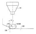
上記のようにヘッダタンク110とチューブ120とが組付けられた後に、接合部130に図1に示す塗布機10によってろう材140が塗布され、炉中に投入されてヘッダタンク110およびチューブ120は一体でろう付けされる。(フィン150は、クラッドろう材によりチューブ120にろう付けされる。)本発明においては、接合部130へのろう材140の塗布方法に特徴を持たせており、以下その詳細を説明する。
【0018】
まず、図3に示すように、ろう材140の塗布量Mに対するろう材塗布位置aとの相関を予め決定している。この相関は、塗布したろう材140が確実に接合部130に到達して、ろう材140が確実に回るように考慮したものである。
【0019】
一般に、ろう材塗布量Mに対して、ろう材140の粘度ρをパラメータにして、ろう材の広がり寸法bが定まる。両者の関係は、ろう材塗布量Mの増加に伴って広がり寸法bも増加する。尚、粘度ρが小さい程、広がり寸法bは大きくなる。
【0020】
そして、ろう材塗布位置aを接合部130からの距離として定義し、図3中の斜線部で示すように、広がり寸法bの1/2よりも小さくなるように決定している。これは、図1に示すように、ろう材140が必ず接合部130に届くように考慮したものである。
【0021】
この図3に示す相関に基づいて、基本的には接合部130に必要とされるろう材量をろう材塗布量Mとして決定し、更にはろう材塗布位置aを決定し、ろう材140の塗布状態を管理する。
【0022】
あるいは、部材間の接合部(130)の形状によっては、安定してろう材140を塗布可能となるろう材塗布位置aが逆に決められるとすると、それに対応するろう材塗布量Mを決定してろう材140の塗布状態を管理する。
【0023】
具体的なろう材140の塗布方法については、図2に示すように、ここでは、凝縮機100の熱交換時における外部流体、即ち冷却空気の流れ方向の一方側(図2(a))から接合部130の全長に対して部分的(図2(b))にペースト状のろう材140を塗布するようにしている。ここで接合部130の全長とは、チューブ120が嵌合する嵌合孔111の全周に対応する。そして、ろう材140をチューブ120の積層方向に連続的に塗布するようにしている。
【0024】
尚、ろう付け時には、図2に示すように、凝縮機100を冷却空気の流れ方向が天地方向となるようにし、ろう材140を上側とすることで溶融したろう材140が重力によって垂れ下がり、また接合部130のクリアランスへ流れ込むことによって、嵌合孔111とチューブ120間の全周に回り、ろう付けが成されるようにしている。
【0025】
以上のように、ろう材塗布量Mとろう材塗布位置aとの相関を予め定めることにより、接合部130の形状によらず、ろう材塗布位置aあるいはろう材塗布量Mが容易に決定でき、両者の関係を管理することで不要なろう材を使用すること無く確実なろう付けが可能となる。
【0026】
また、ろう材塗布位置aは、ろう材の広がり寸法bとの関係から定めるようにしているので(本実施形態では、aはbの1/2よりも小さくする)、ろう材塗布量Mとろう材塗布位置aとの相関を容易に決定できる。
【0027】
更に、ろう材140の塗布を、接合部130に対して部分的に、即ち凝縮機100に対する冷却空気流れ方向の一方側に行なうようにしているので、容易にろう材140を塗布することができる。
【0028】
(第2実施形態)
本発明の第2実施形態を図4、図5に示す。第2実施形態は、上記第1実施形態に対して、更に具体的なろう材塗布装置を設けて、ろう材140の塗布時間を短縮するようにしたものである。
【0029】
ろう材塗布装置は、図4に示すように、凝縮機100を搬送する搬送手段としてのコンベア20と、ろう材塗布手段としてのろう材塗布機10が備えられている。コンベア20にはヘッダタンク110、チューブ120、フィン150等が組付けされた状態の凝縮機100が乗せられて、図5に示すように、コンベア20の進行方向に接合部130が並ぶようにしている。
【0030】
一方、ろう材塗布機10には、ろう材140が貯留されるろう材容器40が継手50によって接続されている。フィルターレギュレータ30は供給されるエア圧を調整するもので、所定のエア圧をろう材容器40に負荷して、このろう材容器40内のろう材140をろう材塗布機10側に供給するようにしている。
【0031】
また、コントローラ60は、フィルターレギュレータ30からのエア圧をろう材塗布機10に負荷すると共に、ろう材塗布機10の下端側のろう材塗布口の開閉を行なうことで、ろう材塗布機10から凝縮機100にろう材140が塗布されるようにしている。
【0032】
更に、ろう材塗布機10は、凝縮機100へのろう材140塗布時に、図5中の破線矢印で示すように、コンベア20の進行方向とは逆方向に移動するようにしている。
【0033】
これにより、凝縮機100の接合部130には、コンベア20の進行速度に加えてろう材塗布機10の逆方向の移動速度が加算されて、ろう材140が塗布されることになるので、ろう材140の塗布時間を短縮して、生産性を向上できる。
【0034】
尚、当然のことながら、ろう材140の塗布は、ろう材塗布機10をコンベア20上で2つ設けて、チューブ120の両端側の接合部130に同時に行なうようにするのが良い。
【0035】
(その他の実施形態)
上記実施形態では、凝縮器100のヘッダタンク110とチューブ120との接合部130を代表部位として説明したが、これに限定されるものでは無く、2つの部材をろう付け接合する部位(例えば、熱交換器におけるタンクとコネクタ、サイドプレートとブラケットのろう付け等)に広く適用できる。
【0036】
また、ろう材塗布位置aは、接合部130からの距離として定義するようにしたが、これに限らず、接合部130との位置関係を明確にした他の部位を基準にして、ろう材塗布位置を決定するようにしても良い。
【0037】
更に、ろう材140塗布のバリエーションとして、図6に示すように、接合部130に合わせて所定間隔(ここでは、チューブ120の積層ピッチ)を持って塗布するようにしても良い。また、チューブ120が例えば2列配置のものにおいては、図7(a)〜(c)に示すように部分的にろう材140を塗布するようにしても良い。
【図面の簡単な説明】
【図1】本発明の第1実施形態におけるろう材塗布時の各寸法関係を示す模式図である。
【図2】凝縮器を示す(a)は断面図、(b)は正面図である。
【図3】ろう材塗布量に対するろう材塗布位置を示す相関図である。
【図4】本発明の第2実施形態におけるろう材塗布装置を示す全体構成図である。
【図5】図4におけるコンベアおよびろう材塗布機の進行方向を示す平面図である。
【図6】その他の実施形態におけるろう材の塗布状態を示す平面図である。
【図7】その他の実施形態におけるろう材の塗布状態を示すチューブ側から見た矢視図である。
【符号の説明】
10 ろう材塗布機(ろう材塗布手段)
20 コンベア(搬送手段)
110 ヘッダタンク(部材)
120 チューブ(部材)
130 接合部
140 ろう材
a ろう材塗布位置
b 広がり寸法
M ろう材塗布量[0001]
BACKGROUND OF THE INVENTION
The present invention relates to a method for applying a brazing material when brazing members together.
[0002]
[Prior art]
As a conventional method for applying a brazing material, a method in which a brazing material is previously applied to the entire surface of a member, such as cladding or thermal spraying, is often used.
[0003]
[Problems to be solved by the invention]
However, if an insufficient case occurs in the brazed state at the joint between the members, the countermeasure is usually taken by increasing the cladding rate or the amount of coating, which will be required for the joint. There was no method to positively control the amount of material, and the amount of brazing material at non-joined parts was increased unnecessarily.
[0004]
In view of the above problems, an object of the present invention is to provide a brazing material coating method capable of reliably joining a joining portion with a required amount of brazing material.
[0005]
[Means for Solving the Problems]
In order to achieve the above object, the present invention employs the following technical means.
[0006]
The invention according to claim 1 is a method of applying a brazing material when brazing members (110, 120) together, the amount of brazing material application (M) and the joint between the members (110, 120). A correlation with the brazing material application position (a) that can reach (130) is determined in advance, the brazing material application position (a) or the brazing material application amount (M) is determined based on this correlation, and the member (110, 120) is assembled, and then a brazing material (140) is applied.
[0007]
Accordingly, the brazing material application position (a) or the brazing material application amount (M) can be easily determined regardless of the shape of the joint (130), and an unnecessary brazing material is used by managing the relationship between the two. Secure brazing is possible without any problems.
[0008]
In the invention described in claim 2, the brazing material application position (a) is defined by a distance (a) from the joint (130), and this distance (a) is in accordance with the brazing material application amount (M). It is characterized in that it is determined to be smaller than 1/2 of the spread dimension (b) of the brazing material (140).
[0009]
Thereby, the correlation between the brazing material application amount (M) and the brazing material application position (a) can be easily determined.
[0010]
If the brazing material (140) is applied partially to the entire length of the joint (130) as in the invention described in claim 3, the member (110, 120) or the joint The degree of freedom of correspondence according to the shape of (130) can be increased.
[0011]
As in the invention described in claim 4, when the members (110, 120) are the header tank (110) and the plurality of tubes (120) in the heat exchanger (100), the brazing material (140) If the application is performed on at least one side in the direction of external fluid flow with respect to the heat exchanger (100), the brazing material (140) can be easily applied.
[0012]
Further, as in the invention described in claim 5, a conveying means (20) for conveying the assembled members (110, 120) and a brazing material applying means (10) for applying the brazing material (140). The assembly means (20) conveys the assembled members (110, 120) in the direction in which the joint (130) continues, and advances the brazing material application means (10) in the direction opposite to the conveyance direction. However, if the brazing material (140) is applied, the application time of the brazing material (140) can be shortened and the productivity can be improved.
[0013]
In addition, the code | symbol in the bracket | parenthesis of each said means shows a corresponding relationship with the specific means of embodiment description mentioned later.
[0014]
DETAILED DESCRIPTION OF THE INVENTION
(First embodiment)
A first embodiment of the present invention is shown in FIGS. In the present embodiment, the present invention is applied to the
[0015]
As shown in FIG. 2, the
[0016]
The
[0017]
After the
[0018]
First, as shown in FIG. 3, the correlation with the brazing material application position a with respect to the coating amount M of the
[0019]
In general, the spread size b of the brazing material is determined with respect to the coating amount M of the brazing material, using the viscosity ρ of the
[0020]
Then, the brazing material application position a is defined as a distance from the
[0021]
Based on the correlation shown in FIG. 3, the brazing material amount required for the
[0022]
Alternatively, depending on the shape of the joint (130) between the members, if the brazing material application position a at which the
[0023]
As for a specific method of applying the
[0024]
At the time of brazing, as shown in FIG. 2, the flow of the cooling air in the
[0025]
As described above, by determining the correlation between the brazing material application amount M and the brazing material application position a in advance, the brazing material application position a or the brazing material application amount M can be easily determined regardless of the shape of the joint 130. By managing the relationship between the two, reliable brazing can be performed without using unnecessary brazing material.
[0026]
Further, since the brazing material application position a is determined from the relationship with the spreading dimension b of the brazing material (in this embodiment, a is smaller than 1/2 of b), the brazing material application amount M and The correlation with the brazing material application position a can be easily determined.
[0027]
Furthermore, since the
[0028]
(Second Embodiment)
A second embodiment of the present invention is shown in FIGS. In the second embodiment, a more specific brazing material application device is provided to shorten the coating time of the
[0029]
As shown in FIG. 4, the brazing material application apparatus includes a
[0030]
On the other hand, a brazing
[0031]
In addition, the
[0032]
Further, the
[0033]
As a result, the
[0034]
As a matter of course, the
[0035]
(Other embodiments)
In the said embodiment, although the
[0036]
The brazing material application position a is defined as the distance from the joint 130, but is not limited thereto, and the brazing material application position a is based on other parts where the positional relationship with the joint 130 is clarified. The position may be determined.
[0037]
Furthermore, as a variation of the
[Brief description of the drawings]
BRIEF DESCRIPTION OF DRAWINGS FIG. 1 is a schematic diagram showing dimensional relationships when a brazing material is applied in a first embodiment of the present invention.
2A is a cross-sectional view showing a condenser, and FIG. 2B is a front view thereof.
FIG. 3 is a correlation diagram showing a brazing material coating position with respect to a brazing material coating amount.
FIG. 4 is an overall configuration diagram showing a brazing material coating apparatus in a second embodiment of the present invention.
5 is a plan view showing the traveling direction of the conveyor and the brazing material applicator in FIG. 4. FIG.
FIG. 6 is a plan view showing a coating state of a brazing material in another embodiment.
FIG. 7 is an arrow view seen from the tube side showing the state of application of the brazing material in another embodiment.
[Explanation of symbols]
10 Brazing material coating machine (brazing material coating means)
20 Conveyor (conveying means)
110 Header tank (member)
120 Tube (member)
130
Claims (5)
Translated fromJapaneseろう材塗布量(M)と、前記部材(110、120)同士の接合部(130)に到達し得るろう材塗布位置(a)との相関を予め定め、
前記相関に基づいて前記ろう材塗布位置(a)あるいは前記ろう材塗布量(M)を決定して、
前記部材(110、120)を組付けた後に、前記ろう材(140)を塗布することを特徴とするろう材の塗布方法。A method of applying a brazing material when brazing members (110, 120),
A correlation between the brazing material application amount (M) and the brazing material application position (a) that can reach the joint (130) between the members (110, 120) is determined in advance.
The brazing material application position (a) or the brazing material application amount (M) is determined based on the correlation,
After assembling the members (110, 120), the brazing material (140) is applied.
前記距離(a)は、前記ろう材塗布量(M)に応じて定まる前記ろう材(140)の広がり寸法(b)の1/2よりも小さくなるように決定されることを特徴とする請求項1に記載のろう材の塗布方法。The brazing material application position (a) is defined by the distance (a) from the joint (130),
The distance (a) is determined to be smaller than ½ of a spread dimension (b) of the brazing material (140) determined according to the brazing material application amount (M). Item 2. A brazing material coating method according to Item 1.
前記ろう材(140)の塗布は、前記熱交換器(100)に対する外部流体流れ方向の少なくとも一方側に行なわれるようにしたことを特徴とする請求項1〜請求項3のいずれかに記載のろう材の塗布方法。The members (110, 120) are a header tank (110) and a plurality of tubes (120) in the heat exchanger (100),
The application of the brazing material (140) is performed on at least one side of an external fluid flow direction with respect to the heat exchanger (100). How to apply brazing material.
前記搬送手段(20)によって、組付けされた前記部材(110、120)を前記接合部(130)の連続する方向に搬送し、
前記ろう材塗布手段(10)を前記搬送方向とは逆方向に進ませながら前記ろう材(140)を塗布するようにしたことを特徴とする請求項1〜請求項4のいずれかに記載のろう材の塗布方法。A conveying means (20) for conveying the assembled members (110, 120) and a brazing material applying means (10) for applying the brazing material (140);
The member (110, 120) assembled by the transport means (20) is transported in the continuous direction of the joint (130),
5. The brazing material (140) is applied while the brazing material application means (10) is moved in the direction opposite to the conveying direction. 6. How to apply brazing material.
Priority Applications (2)
| Application Number | Priority Date | Filing Date | Title |
|---|---|---|---|
| JP2002109280AJP3899986B2 (en) | 2002-01-25 | 2002-04-11 | How to apply brazing material |
| US10/350,463US6880744B2 (en) | 2002-01-25 | 2003-01-24 | Method of applying brazing material |
Applications Claiming Priority (3)
| Application Number | Priority Date | Filing Date | Title |
|---|---|---|---|
| JP2002-17154 | 2002-01-25 | ||
| JP2002017154 | 2002-01-25 | ||
| JP2002109280AJP3899986B2 (en) | 2002-01-25 | 2002-04-11 | How to apply brazing material |
Publications (2)
| Publication Number | Publication Date |
|---|---|
| JP2003285160A JP2003285160A (en) | 2003-10-07 |
| JP3899986B2true JP3899986B2 (en) | 2007-03-28 |
Family
ID=27615701
Family Applications (1)
| Application Number | Title | Priority Date | Filing Date |
|---|---|---|---|
| JP2002109280AExpired - Fee RelatedJP3899986B2 (en) | 2002-01-25 | 2002-04-11 | How to apply brazing material |
Country Status (2)
| Country | Link |
|---|---|
| US (1) | US6880744B2 (en) |
| JP (1) | JP3899986B2 (en) |
Families Citing this family (61)
| Publication number | Priority date | Publication date | Assignee | Title |
|---|---|---|---|---|
| US8109349B2 (en) | 2006-10-26 | 2012-02-07 | Schlumberger Technology Corporation | Thick pointed superhard material |
| JP2006348372A (en)* | 2005-06-20 | 2006-12-28 | Mitsubishi Alum Co Ltd | High strength aluminum alloy material for automobile heat-exchanger |
| JP2007205585A (en)* | 2006-01-31 | 2007-08-16 | Denso Corp | Manufacturing method of heat exchanger, and heat exchanger |
| US8274014B2 (en) | 2006-05-25 | 2012-09-25 | Bellman-Melcor Development, Llc | Filler metal with flux for brazing and soldering and method of making and using same |
| US7950746B2 (en) | 2006-06-16 | 2011-05-31 | Schlumberger Technology Corporation | Attack tool for degrading materials |
| US7568770B2 (en) | 2006-06-16 | 2009-08-04 | Hall David R | Superhard composite material bonded to a steel body |
| US7661765B2 (en) | 2006-08-11 | 2010-02-16 | Hall David R | Braze thickness control |
| US8500209B2 (en) | 2006-08-11 | 2013-08-06 | Schlumberger Technology Corporation | Manually rotatable tool |
| US8414085B2 (en) | 2006-08-11 | 2013-04-09 | Schlumberger Technology Corporation | Shank assembly with a tensioned element |
| US8500210B2 (en) | 2006-08-11 | 2013-08-06 | Schlumberger Technology Corporation | Resilient pick shank |
| US7744164B2 (en) | 2006-08-11 | 2010-06-29 | Schluimberger Technology Corporation | Shield of a degradation assembly |
| US7648210B2 (en) | 2006-08-11 | 2010-01-19 | Hall David R | Pick with an interlocked bolster |
| US8292372B2 (en) | 2007-12-21 | 2012-10-23 | Hall David R | Retention for holder shank |
| US8136887B2 (en) | 2006-08-11 | 2012-03-20 | Schlumberger Technology Corporation | Non-rotating pick with a pressed in carbide segment |
| US7387345B2 (en) | 2006-08-11 | 2008-06-17 | Hall David R | Lubricating drum |
| US7871133B2 (en) | 2006-08-11 | 2011-01-18 | Schlumberger Technology Corporation | Locking fixture |
| US8485609B2 (en) | 2006-08-11 | 2013-07-16 | Schlumberger Technology Corporation | Impact tool |
| US7997661B2 (en) | 2006-08-11 | 2011-08-16 | Schlumberger Technology Corporation | Tapered bore in a pick |
| US7963617B2 (en) | 2006-08-11 | 2011-06-21 | Schlumberger Technology Corporation | Degradation assembly |
| US8201892B2 (en) | 2006-08-11 | 2012-06-19 | Hall David R | Holder assembly |
| US8123302B2 (en) | 2006-08-11 | 2012-02-28 | Schlumberger Technology Corporation | Impact tool |
| US8590644B2 (en)* | 2006-08-11 | 2013-11-26 | Schlumberger Technology Corporation | Downhole drill bit |
| US8567532B2 (en) | 2006-08-11 | 2013-10-29 | Schlumberger Technology Corporation | Cutting element attached to downhole fixed bladed bit at a positive rake angle |
| US7992945B2 (en) | 2006-08-11 | 2011-08-09 | Schlumberger Technology Corporation | Hollow pick shank |
| US8622155B2 (en) | 2006-08-11 | 2014-01-07 | Schlumberger Technology Corporation | Pointed diamond working ends on a shear bit |
| US8007051B2 (en) | 2006-08-11 | 2011-08-30 | Schlumberger Technology Corporation | Shank assembly |
| US8453497B2 (en) | 2006-08-11 | 2013-06-04 | Schlumberger Technology Corporation | Test fixture that positions a cutting element at a positive rake angle |
| US8215420B2 (en) | 2006-08-11 | 2012-07-10 | Schlumberger Technology Corporation | Thermally stable pointed diamond with increased impact resistance |
| US9051795B2 (en) | 2006-08-11 | 2015-06-09 | Schlumberger Technology Corporation | Downhole drill bit |
| US7946657B2 (en) | 2006-08-11 | 2011-05-24 | Schlumberger Technology Corporation | Retention for an insert |
| US7600823B2 (en) | 2006-08-11 | 2009-10-13 | Hall David R | Pick assembly |
| US7469971B2 (en) | 2006-08-11 | 2008-12-30 | Hall David R | Lubricated pick |
| US9145742B2 (en) | 2006-08-11 | 2015-09-29 | Schlumberger Technology Corporation | Pointed working ends on a drill bit |
| US7637574B2 (en) | 2006-08-11 | 2009-12-29 | Hall David R | Pick assembly |
| US8449040B2 (en) | 2006-08-11 | 2013-05-28 | David R. Hall | Shank for an attack tool |
| US7669674B2 (en) | 2006-08-11 | 2010-03-02 | Hall David R | Degradation assembly |
| US7390066B2 (en) | 2006-08-11 | 2008-06-24 | Hall David R | Method for providing a degradation drum |
| US8714285B2 (en) | 2006-08-11 | 2014-05-06 | Schlumberger Technology Corporation | Method for drilling with a fixed bladed bit |
| US7992944B2 (en) | 2006-08-11 | 2011-08-09 | Schlumberger Technology Corporation | Manually rotatable tool |
| US9068410B2 (en) | 2006-10-26 | 2015-06-30 | Schlumberger Technology Corporation | Dense diamond body |
| US8960337B2 (en) | 2006-10-26 | 2015-02-24 | Schlumberger Technology Corporation | High impact resistant tool with an apex width between a first and second transitions |
| US7976239B2 (en) | 2006-12-01 | 2011-07-12 | Hall David R | End of a moldboard positioned proximate a milling drum |
| US8485756B2 (en) | 2006-12-01 | 2013-07-16 | David R. Hall | Heated liquid nozzles incorporated into a moldboard |
| US8403595B2 (en) | 2006-12-01 | 2013-03-26 | David R. Hall | Plurality of liquid jet nozzles and a blower mechanism that are directed into a milling chamber |
| US9051794B2 (en) | 2007-04-12 | 2015-06-09 | Schlumberger Technology Corporation | High impact shearing element |
| DE102008018209B4 (en) | 2007-04-23 | 2013-05-29 | Modine Korea LLC. | Main pipe of a heat exchanger with guide grooves for filler metal |
| US7926883B2 (en) | 2007-05-15 | 2011-04-19 | Schlumberger Technology Corporation | Spring loaded pick |
| US8038223B2 (en) | 2007-09-07 | 2011-10-18 | Schlumberger Technology Corporation | Pick with carbide cap |
| US7832808B2 (en) | 2007-10-30 | 2010-11-16 | Hall David R | Tool holder sleeve |
| US8646848B2 (en) | 2007-12-21 | 2014-02-11 | David R. Hall | Resilient connection between a pick shank and block |
| US8540037B2 (en) | 2008-04-30 | 2013-09-24 | Schlumberger Technology Corporation | Layered polycrystalline diamond |
| US8061457B2 (en) | 2009-02-17 | 2011-11-22 | Schlumberger Technology Corporation | Chamfered pointed enhanced diamond insert |
| US8322796B2 (en) | 2009-04-16 | 2012-12-04 | Schlumberger Technology Corporation | Seal with contact element for pick shield |
| US8701799B2 (en) | 2009-04-29 | 2014-04-22 | Schlumberger Technology Corporation | Drill bit cutter pocket restitution |
| US8262168B2 (en) | 2010-09-22 | 2012-09-11 | Hall David R | Multiple milling drums secured to the underside of a single milling machine |
| US8261471B2 (en) | 2010-06-30 | 2012-09-11 | Hall David R | Continuously adjusting resultant force in an excavating assembly |
| US8728382B2 (en) | 2011-03-29 | 2014-05-20 | David R. Hall | Forming a polycrystalline ceramic in multiple sintering phases |
| US8668275B2 (en) | 2011-07-06 | 2014-03-11 | David R. Hall | Pick assembly with a contiguous spinal region |
| EP2902146A1 (en)* | 2014-02-04 | 2015-08-05 | Aurubis AG | Procedure and apparatus for joining anneal resistant metal components |
| US9731383B2 (en) | 2014-07-09 | 2017-08-15 | Bellman-Melcor Development, Llc | Filler metal with flux for brazing and soldering and method of using same |
| US10744601B2 (en) | 2015-08-07 | 2020-08-18 | Bellman-Melcor Development, Llc | Bonded brazing ring system and method for adhering a brazing ring to a tube |
Family Cites Families (3)
| Publication number | Priority date | Publication date | Assignee | Title |
|---|---|---|---|---|
| US4722630A (en)* | 1985-09-20 | 1988-02-02 | The Garrett Corporation | Ceramic-metal braze joint |
| US5360158A (en)* | 1993-07-15 | 1994-11-01 | The S.A. Day Mfg. Co., Inc. | Method for joining aluminum alloy tubes |
| US6078028A (en)* | 1999-02-19 | 2000-06-20 | Saint-Gobain Industrial Ceramics, Inc. | Solderless ceramic igniter having a leadframe attachment |
- 2002
- 2002-04-11JPJP2002109280Apatent/JP3899986B2/ennot_activeExpired - Fee Related
- 2003
- 2003-01-24USUS10/350,463patent/US6880744B2/ennot_activeExpired - Fee Related
Also Published As
| Publication number | Publication date |
|---|---|
| US20030141350A1 (en) | 2003-07-31 |
| US6880744B2 (en) | 2005-04-19 |
| JP2003285160A (en) | 2003-10-07 |
Similar Documents
| Publication | Publication Date | Title |
|---|---|---|
| JP3899986B2 (en) | How to apply brazing material | |
| CA2145555C (en) | Differential coating for micro extruded tubes used in parallel flow heat exchangers | |
| CN100434855C (en) | Heat exchanger for industrial installations | |
| EA007521B1 (en) | Method of manufacturing heat transfer tubes | |
| JP2019516563A (en) | Method and apparatus for manufacturing a brazed heat exchanger | |
| CN102338570A (en) | Heat exchanger structure and assembly process thereof | |
| JP2001194080A (en) | Heat exchanger | |
| JP2002011569A (en) | Heat exchanger and its manufacture | |
| CN102338587A (en) | Heat exchanger structure and assembly process thereof | |
| JP6341098B2 (en) | Manufacturing method of parallel flow type heat exchanger | |
| KR20080093105A (en) | Method for manufacturing the metal part | |
| JP2015117875A (en) | Parallel flow heat exchanger and manufacturing method thereof | |
| US7273094B2 (en) | Cooling fin unit | |
| JP2001241870A (en) | Small-diameter tunnel plate heat pipe | |
| EP1669150B1 (en) | Braze bar carrier system comprising a braze bar having a pair of pins and an insert formed of dense graphit material | |
| JP4148096B2 (en) | Dry flux applicator | |
| JP2002178074A (en) | Device and method of manufacturing heat exchanger tube | |
| JPH0577039A (en) | Manufacture of header pipe for heat exchanger | |
| AU5591301A (en) | Method of making a tube for a heat exchanger | |
| JP2008304159A (en) | Manufacturing method of heat exchanger | |
| WO2020100897A1 (en) | Heat exchanger and heat exchanger manufacturing method | |
| CN106482566A (en) | For the heat exchanger tube of heat exchanger, heat exchanger and its assembly method | |
| JP3770684B2 (en) | Aluminum alloy heat exchanger | |
| CN1995894A (en) | Loop type heat pipe structure | |
| JP3090716B2 (en) | Brazing method for heat transfer tubes and fins of aluminum heat exchanger |
Legal Events
| Date | Code | Title | Description |
|---|---|---|---|
| A621 | Written request for application examination | Free format text:JAPANESE INTERMEDIATE CODE: A621 Effective date:20040513 | |
| A977 | Report on retrieval | Free format text:JAPANESE INTERMEDIATE CODE: A971007 Effective date:20060511 | |
| TRDD | Decision of grant or rejection written | ||
| A01 | Written decision to grant a patent or to grant a registration (utility model) | Free format text:JAPANESE INTERMEDIATE CODE: A01 Effective date:20061205 | |
| A61 | First payment of annual fees (during grant procedure) | Free format text:JAPANESE INTERMEDIATE CODE: A61 Effective date:20061218 | |
| R150 | Certificate of patent or registration of utility model | Free format text:JAPANESE INTERMEDIATE CODE: R150 | |
| LAPS | Cancellation because of no payment of annual fees |