JP3898666B2 - Solid-state imaging device and manufacturing method thereof - Google Patents
Solid-state imaging device and manufacturing method thereofDownload PDFInfo
- Publication number
- JP3898666B2 JP3898666B2JP2003123843AJP2003123843AJP3898666B2JP 3898666 B2JP3898666 B2JP 3898666B2JP 2003123843 AJP2003123843 AJP 2003123843AJP 2003123843 AJP2003123843 AJP 2003123843AJP 3898666 B2JP3898666 B2JP 3898666B2
- Authority
- JP
- Japan
- Prior art keywords
- solid
- state imaging
- substrate
- rib
- imaging device
- Prior art date
- Legal status (The legal status is an assumption and is not a legal conclusion. Google has not performed a legal analysis and makes no representation as to the accuracy of the status listed.)
- Expired - Fee Related
Links
Images


Classifications
- H—ELECTRICITY
- H10—SEMICONDUCTOR DEVICES; ELECTRIC SOLID-STATE DEVICES NOT OTHERWISE PROVIDED FOR
- H10F—INORGANIC SEMICONDUCTOR DEVICES SENSITIVE TO INFRARED RADIATION, LIGHT, ELECTROMAGNETIC RADIATION OF SHORTER WAVELENGTH OR CORPUSCULAR RADIATION
- H10F99/00—Subject matter not provided for in other groups of this subclass
- H—ELECTRICITY
- H10—SEMICONDUCTOR DEVICES; ELECTRIC SOLID-STATE DEVICES NOT OTHERWISE PROVIDED FOR
- H10F—INORGANIC SEMICONDUCTOR DEVICES SENSITIVE TO INFRARED RADIATION, LIGHT, ELECTROMAGNETIC RADIATION OF SHORTER WAVELENGTH OR CORPUSCULAR RADIATION
- H10F39/00—Integrated devices, or assemblies of multiple devices, comprising at least one element covered by group H10F30/00, e.g. radiation detectors comprising photodiode arrays
- H10F39/80—Constructional details of image sensors
- H10F39/804—Containers or encapsulations
- H—ELECTRICITY
- H01—ELECTRIC ELEMENTS
- H01L—SEMICONDUCTOR DEVICES NOT COVERED BY CLASS H10
- H01L23/00—Details of semiconductor or other solid state devices
- H—ELECTRICITY
- H01—ELECTRIC ELEMENTS
- H01L—SEMICONDUCTOR DEVICES NOT COVERED BY CLASS H10
- H01L24/00—Arrangements for connecting or disconnecting semiconductor or solid-state bodies; Methods or apparatus related thereto
- H01L24/93—Batch processes
- H01L24/95—Batch processes at chip-level, i.e. with connecting carried out on a plurality of singulated devices, i.e. on diced chips
- H01L24/97—Batch processes at chip-level, i.e. with connecting carried out on a plurality of singulated devices, i.e. on diced chips the devices being connected to a common substrate, e.g. interposer, said common substrate being separable into individual assemblies after connecting
- H—ELECTRICITY
- H10—SEMICONDUCTOR DEVICES; ELECTRIC SOLID-STATE DEVICES NOT OTHERWISE PROVIDED FOR
- H10F—INORGANIC SEMICONDUCTOR DEVICES SENSITIVE TO INFRARED RADIATION, LIGHT, ELECTROMAGNETIC RADIATION OF SHORTER WAVELENGTH OR CORPUSCULAR RADIATION
- H10F39/00—Integrated devices, or assemblies of multiple devices, comprising at least one element covered by group H10F30/00, e.g. radiation detectors comprising photodiode arrays
- H10F39/011—Manufacture or treatment of image sensors covered by group H10F39/12
- H—ELECTRICITY
- H01—ELECTRIC ELEMENTS
- H01L—SEMICONDUCTOR DEVICES NOT COVERED BY CLASS H10
- H01L2224/00—Indexing scheme for arrangements for connecting or disconnecting semiconductor or solid-state bodies and methods related thereto as covered by H01L24/00
- H01L2224/01—Means for bonding being attached to, or being formed on, the surface to be connected, e.g. chip-to-package, die-attach, "first-level" interconnects; Manufacturing methods related thereto
- H01L2224/26—Layer connectors, e.g. plate connectors, solder or adhesive layers; Manufacturing methods related thereto
- H01L2224/31—Structure, shape, material or disposition of the layer connectors after the connecting process
- H01L2224/32—Structure, shape, material or disposition of the layer connectors after the connecting process of an individual layer connector
- H01L2224/321—Disposition
- H01L2224/32151—Disposition the layer connector connecting between a semiconductor or solid-state body and an item not being a semiconductor or solid-state body, e.g. chip-to-substrate, chip-to-passive
- H01L2224/32221—Disposition the layer connector connecting between a semiconductor or solid-state body and an item not being a semiconductor or solid-state body, e.g. chip-to-substrate, chip-to-passive the body and the item being stacked
- H01L2224/32225—Disposition the layer connector connecting between a semiconductor or solid-state body and an item not being a semiconductor or solid-state body, e.g. chip-to-substrate, chip-to-passive the body and the item being stacked the item being non-metallic, e.g. insulating substrate with or without metallisation
- H—ELECTRICITY
- H01—ELECTRIC ELEMENTS
- H01L—SEMICONDUCTOR DEVICES NOT COVERED BY CLASS H10
- H01L2224/00—Indexing scheme for arrangements for connecting or disconnecting semiconductor or solid-state bodies and methods related thereto as covered by H01L24/00
- H01L2224/01—Means for bonding being attached to, or being formed on, the surface to be connected, e.g. chip-to-package, die-attach, "first-level" interconnects; Manufacturing methods related thereto
- H01L2224/42—Wire connectors; Manufacturing methods related thereto
- H01L2224/47—Structure, shape, material or disposition of the wire connectors after the connecting process
- H01L2224/48—Structure, shape, material or disposition of the wire connectors after the connecting process of an individual wire connector
- H01L2224/4805—Shape
- H01L2224/4809—Loop shape
- H01L2224/48091—Arched
- H—ELECTRICITY
- H01—ELECTRIC ELEMENTS
- H01L—SEMICONDUCTOR DEVICES NOT COVERED BY CLASS H10
- H01L2224/00—Indexing scheme for arrangements for connecting or disconnecting semiconductor or solid-state bodies and methods related thereto as covered by H01L24/00
- H01L2224/01—Means for bonding being attached to, or being formed on, the surface to be connected, e.g. chip-to-package, die-attach, "first-level" interconnects; Manufacturing methods related thereto
- H01L2224/42—Wire connectors; Manufacturing methods related thereto
- H01L2224/47—Structure, shape, material or disposition of the wire connectors after the connecting process
- H01L2224/48—Structure, shape, material or disposition of the wire connectors after the connecting process of an individual wire connector
- H01L2224/481—Disposition
- H01L2224/48151—Connecting between a semiconductor or solid-state body and an item not being a semiconductor or solid-state body, e.g. chip-to-substrate, chip-to-passive
- H01L2224/48221—Connecting between a semiconductor or solid-state body and an item not being a semiconductor or solid-state body, e.g. chip-to-substrate, chip-to-passive the body and the item being stacked
- H01L2224/48225—Connecting between a semiconductor or solid-state body and an item not being a semiconductor or solid-state body, e.g. chip-to-substrate, chip-to-passive the body and the item being stacked the item being non-metallic, e.g. insulating substrate with or without metallisation
- H01L2224/48227—Connecting between a semiconductor or solid-state body and an item not being a semiconductor or solid-state body, e.g. chip-to-substrate, chip-to-passive the body and the item being stacked the item being non-metallic, e.g. insulating substrate with or without metallisation connecting the wire to a bond pad of the item
- H—ELECTRICITY
- H01—ELECTRIC ELEMENTS
- H01L—SEMICONDUCTOR DEVICES NOT COVERED BY CLASS H10
- H01L2224/00—Indexing scheme for arrangements for connecting or disconnecting semiconductor or solid-state bodies and methods related thereto as covered by H01L24/00
- H01L2224/01—Means for bonding being attached to, or being formed on, the surface to be connected, e.g. chip-to-package, die-attach, "first-level" interconnects; Manufacturing methods related thereto
- H01L2224/42—Wire connectors; Manufacturing methods related thereto
- H01L2224/47—Structure, shape, material or disposition of the wire connectors after the connecting process
- H01L2224/48—Structure, shape, material or disposition of the wire connectors after the connecting process of an individual wire connector
- H01L2224/481—Disposition
- H01L2224/48151—Connecting between a semiconductor or solid-state body and an item not being a semiconductor or solid-state body, e.g. chip-to-substrate, chip-to-passive
- H01L2224/48221—Connecting between a semiconductor or solid-state body and an item not being a semiconductor or solid-state body, e.g. chip-to-substrate, chip-to-passive the body and the item being stacked
- H01L2224/48245—Connecting between a semiconductor or solid-state body and an item not being a semiconductor or solid-state body, e.g. chip-to-substrate, chip-to-passive the body and the item being stacked the item being metallic
- H01L2224/48247—Connecting between a semiconductor or solid-state body and an item not being a semiconductor or solid-state body, e.g. chip-to-substrate, chip-to-passive the body and the item being stacked the item being metallic connecting the wire to a bond pad of the item
- H—ELECTRICITY
- H01—ELECTRIC ELEMENTS
- H01L—SEMICONDUCTOR DEVICES NOT COVERED BY CLASS H10
- H01L2224/00—Indexing scheme for arrangements for connecting or disconnecting semiconductor or solid-state bodies and methods related thereto as covered by H01L24/00
- H01L2224/73—Means for bonding being of different types provided for in two or more of groups H01L2224/10, H01L2224/18, H01L2224/26, H01L2224/34, H01L2224/42, H01L2224/50, H01L2224/63, H01L2224/71
- H01L2224/732—Location after the connecting process
- H01L2224/73251—Location after the connecting process on different surfaces
- H01L2224/73265—Layer and wire connectors
- H—ELECTRICITY
- H01—ELECTRIC ELEMENTS
- H01L—SEMICONDUCTOR DEVICES NOT COVERED BY CLASS H10
- H01L2224/00—Indexing scheme for arrangements for connecting or disconnecting semiconductor or solid-state bodies and methods related thereto as covered by H01L24/00
- H01L2224/93—Batch processes
- H01L2224/95—Batch processes at chip-level, i.e. with connecting carried out on a plurality of singulated devices, i.e. on diced chips
- H01L2224/97—Batch processes at chip-level, i.e. with connecting carried out on a plurality of singulated devices, i.e. on diced chips the devices being connected to a common substrate, e.g. interposer, said common substrate being separable into individual assemblies after connecting
- H—ELECTRICITY
- H01—ELECTRIC ELEMENTS
- H01L—SEMICONDUCTOR DEVICES NOT COVERED BY CLASS H10
- H01L2924/00—Indexing scheme for arrangements or methods for connecting or disconnecting semiconductor or solid-state bodies as covered by H01L24/00
- H01L2924/15—Details of package parts other than the semiconductor or other solid state devices to be connected
- H01L2924/161—Cap
- H01L2924/1615—Shape
- H01L2924/16195—Flat cap [not enclosing an internal cavity]
Landscapes
- Engineering & Computer Science (AREA)
- Computer Hardware Design (AREA)
- Microelectronics & Electronic Packaging (AREA)
- Power Engineering (AREA)
- Physics & Mathematics (AREA)
- Condensed Matter Physics & Semiconductors (AREA)
- General Physics & Mathematics (AREA)
- Solid State Image Pick-Up Elements (AREA)
- Transforming Light Signals Into Electric Signals (AREA)
- Camera Bodies And Camera Details Or Accessories (AREA)
Description
Translated fromJapanese【0001】
【発明の属する技術分野】
本発明は、CCD等の撮像素子を基台に搭載して構成される固体撮像装置、およびその製造方法に関する。
【0002】
【従来の技術】
固体撮像装置は、ビデオカメラやスチルカメラ等に広く用いられ、CCD等の撮像素子を絶縁性材料からなる基台に搭載し、受光領域を透光板で覆ったパッケージの形態で提供される。装置の小型化のため、撮像素子は、ベアチップのままで基台に搭載される。そのような固体撮像装置の従来例として、特許文献1に記載の固体撮像装置について、図7を参照して説明する。
【0003】
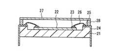
図7において、21は基台であり、その上面に凹部が形成され、凹部の中央に撮像素子チップ22が固定されている。基台21にはリード端子24が設けられ、そのリード側パッド25と撮像素子チップ22のボンディングパッド23とが、金属線よりなるボンディングワイヤ26によって接続されている。また基台21の周縁部上面には、リブ28が設けられ、その上部に、透明なシールガラス板27が固定されて、撮像素子チップ22を保護するためのパッケージが形成されている。
【0004】
このような固体撮像装置は、図示されたようにシールガラス板27の側を上方にむけた状態で、回路基板上に搭載され、リード端子24が、回路基板上の電極と接続するために用いられる。図示しないが、シールガラス板27の上部には、撮像光学系が組み込まれた鏡筒が、撮像素子チップ22に形成された受光領域との相互の位置関係に所定の精度を持たせて装着される。撮像動作の際は、鏡筒に組み込まれた撮像光学系を通して、被撮像対象からの光が受光領域に集光され、光電変換される。
【0005】
【特許文献1】
特開平5−267629号公報
【0006】
【発明が解決しようとする課題】
上記従来例の固体撮像装置は、リード端子24を基台21の側面に配置した構造のため、製造工程が煩雑で、パッケージの小型化が困難である。
【0007】
また、リード端子24の存在により、基台21の端面、リブ28の側面、およびシールガラス板27端面により形成されるパッケージの側面は平坦ではない。光学系を収容した鏡筒を装着する際、パッケージの側面を利用すれば、容易に高精度の位置決めが可能である。すなわち、パッケージの側面と鏡筒の内面の当接により、水平方向を位置決めし、回路基板面と鏡筒の下面との当接により垂直方向の位置決めが可能である。ところが、パッケージの側面が平坦でないと、上述のような位置決め方法では、精度が不安定である。
【0008】
以上のことを考慮して、本発明は、外部端子を有する基台の構造が簡素で、容易に小型化が可能な固体撮像装置を提供することを目的とする。また、パッケージの側面が平坦で、パッケージの側面を利用した鏡筒の位置決めを安定した精度で行うことが可能な固体撮像装置を提供することを目的とする。さらに、そのような固体撮像装置を容易に量産可能な製造方法を提供することを目的とする。
【0009】
【課題を解決するための手段】
本発明の固体撮像装置は、基板と、前記基板の上面に搭載された撮像素子と、前記基板の上面に前記撮像素子を包囲するように設けられたリブと、前記リブの上面に固定された透光板と、前記基板、前記リブ、および前記透光板により形成された空間を内部に有するパッケージの前記内部と外部とを電気的に接続する配線と、前記撮像素子の電極と前記配線とを接続する金属細線とを備える。
【0010】
上記課題を解決するために、前記配線は、前記基板の上面に形成された内部電極と、前記基板の下面に形成された外部電極と、前記内部電極と前記外部電極とを接続し、前記基板の側面に形成された凹部内に配置され、かつ表面が前記基板の端面と同一平面を形成しているか、または前記基板の端面よりも窪んでいる端面電極とを含み、一括切断により形成された前記基板の前記側面、前記リブの外側面および前記透明板の側面が、同一平面を形成している。
【0011】
本発明の固体撮像装置の製造方法は、上記構成の固体撮像装置を製造する方法であって、以下の工程を特徴とする。
【0012】
すなわち、まず、複数個の固体撮像装置を形成する基材の上下面に各々上面導電層および下面導電層を形成し、かつ前記上面導電層と前記下面導電層とを前記基材を貫通して接続する貫通導電層を前記複数個の固体撮像装置を形成する各領域の境界に形成する。次に、前記基材上にリブを形成するためのリブ形成部材を、前記各領域の境界で、前記貫通導電層の上方位置に樹脂成形により設ける。次に、前記撮像素子を前記リブ形成部材により包囲された前記各領域内の前記基材の上面に固定して、前記撮像素子の電極と前記各上面導電層とを前記金属細線により接続し、さらに、前記リブ形成部材の上端面に前記透明板を固定する。次に、前記基材、前記リブ形成部材、前記貫通導電層および前記透明板を、前記基材の平面方向に直交する方向であって、かつ平面形状において前記各リブ形成部材の幅を2分する方向に一括して切断して、前記複数個の固体撮像装置を各個片の固体撮像装置に分離する。
【0013】
【発明の実施の形態】
本発明の固体撮像装置は、上述のとおり、基板、リブ、および透光板により形成されたパッケージ内で、基板上に撮像素子が固定された構造をとる。そして、パッケージ内部から外部に電気的な導出を行うための複数の配線が、各々撮像素子の搭載面に形成された内部電極と、その裏面の内部電極と対応する位置に形成された外部電極と、基板の端面に形成されて内部電極と外部電極とを接続する端面電極とを含むこと、および、パッケージの各側面に対応する、基板の端面、リブの側面および透明板の端面が、実質的に同一平面を形成していることを特徴とする。
【0014】
この構成によれば、基板が簡素な配線基板を用いて形成され、基板の上面から端面を経由して下面に至る範囲の配線を、メッキにより容易に形成することができる。したがって、パッケージの小型化が容易である。また、パッケージ側面が平坦であるため、光学系を収容した鏡筒を装着する際、パッケージ側面と鏡筒の内面の当接により鏡筒を位置決めして、高い位置精度を確保することができる。
【0015】
上記の構成において、前記外部電極は前記基板の前記内部電極が形成された部分の裏側に形成されていることが好ましい。リブの内側面は、基板面から透光板に向かって開く向きの傾斜を有することが好ましい。それにより、リブの内側面による入射光の反射を、撮像機能に実質的な悪影響を与えないようにすることができる。その場合、リブの内側面は平面とし、傾斜の角度は、基板面に直交する方向に対して2〜12°の範囲とすることができる。あるいは、リブの内側面に、梨地またはシボを形成してもよい。一方、リブの内側面が平面で、リブの外側面および内側面が基板面に直交している構成としてもよい。
【0016】
また、基板の裏面に絶縁膜が形成され、絶縁膜と外部電極とは、互いに重畳部分を持たないように配置された構成とすることができる。または、外部電極の周縁部が絶縁膜と互いに重なり合うように配置されててもよい。外部電極の表面は、絶縁膜の表面と同一平面を形成している構成とすることができる。あるいは、外部電極の表面は、絶縁膜の表面よりも窪んでいる構成としてもよい。
【0017】
基板の裏面に絶縁膜が形成され、前記絶縁膜と前記外部電極とは、互いに重畳部分を持たないように配置された構成とすることができる。または、外部電極の周縁部が絶縁膜と互いに重なり合うように配置されてもよい。
【0018】
本発明の固体撮像装置の製造方法では、上記構成の複数個の固体撮像装置に対応させて複数組の配線を形成するため、平板状基材に、上面導電層、下面導電層、およびその両導電層を接続する貫通導電層を形成する。そして、リブ形成部材を、貫通導電層の上方位置で上面導電層を横断するように設け、撮像素子を搭載し、透明板を固定した後、基材、リブ形成部材および透明板を一括して切断して、各固体撮像装置を個片に分離する。この製造方法によれば、リブはリブ形成部材の半分の幅になり、小型化に有利である。また、基材、リブ形成部材および透明板を一括して切断することにより、基板の端面、リブの側面および透明板の端面が形成する平面は、実質的に同一平面となり、良好な平坦度を得ることができる。
【0019】
上記の製造方法において、リブ形成部材を格子状に形成することが好ましい。また、基材上にリブ形成部材を樹脂成形により形成することが好ましい。樹脂成形は金型を用いて行うことができる。これらは、多数の撮像素子を効率的に製造するために効果的である。さらに、リブ形成部材を樹脂成形により形成する際に、前記樹脂成形用の金型と前記基材との間に、樹脂フラッシュバリの発生を抑制するためのシートを介在させることが好ましい。
【0020】
以下、本発明の実施の形態について、図面を参照して具体的に説明する。
【0021】
(実施の形態1)
図1は、実施の形態1における固体撮像装置の断面図、図2は側面図である。図3は図2の下面を示す図である。
【0022】
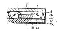
基板1は平板状であり、通常の配線基板に用いられる絶縁性の樹脂、例えばガラスエポキシ樹脂からなる。基板1上に撮像素子2が固定され、その撮像素子2を包囲するように、基板1上に矩形枠の平面形状を有するリブ3が設けられている。リブ3は、例えばエポキシ樹脂からなり、樹脂成形により基板1上に、例えば0.3〜1.0mmの高さで設けられる。リブ3の上面には、透光板4が接着剤5により固定されている。基板1、リブ3、および透光板4により、内部に空間を有するパッケージが形成され、その内部から外部に電気的な導出を行うための複数の配線6が形成されている。撮像素子2の電極(図示せず)と各配線6とを接続する金属細線7が、パッケージの空間内に設けられている。パッケージ全体の厚みは、2.0mm以下とする。
【0023】
配線6は、撮像素子2の搭載面に形成された内部電極6aと、その裏面に形成された外部電極6bと、基板1の端面に形成された端面電極6cとからなる。外部電極6bは、内部電極6aと対応する位置に配置されている。端面電極6cは、内部電極6aと外部電極6bとを接続している。内部電極6a、外部電極6b、および端面電極6cはいずれも、例えば、メッキにより形成することができる。図3に示すように、端面電極6cは、基板1の端面に形成された凹部1aに配置されている。端面電極6cの表面は、基板1の端面と実質的に同一平面を形成しているか、または基板1の端面よりも窪んでいる。
【0024】
基板1の両面における、内部電極6aと外部電極6bの周囲の領域には、絶縁膜8a、8bが形成されている(図3には絶縁膜8bを図示せず)。外部電極6bの表面は、図示したように絶縁膜8bの表面よりも窪んでいるか、あるいは、絶縁膜8bの表面と実質的に同一平面を形成している。絶縁膜8bと外部電極6bとは、互いに重畳部分を有さないように配置されていても、外部電極6bの周縁部が絶縁膜8bと互いに重なり合うように配置されていてもよい。
【0025】
パッケージの各側面に対応する、基板1の端面、リブ3の側面および透明板4の端面は、実質的に同一平面内にあり、平坦なパッケージ側面を形成している。このパッケージ側面は、例えば、製造工程において基板1の端面、リブ3の側面および透明板4の端面を一括して切断することにより、良好な平坦度の平面を形成することができる。
【0026】
以上の構成によれば、基板1は、簡素な配線基板を用いて形成され、基板1の上面から端面を経由して下面に至る範囲の配線6を、メッキにより容易に形成することができる。したがって、パッケージの小型化が容易である。また、外部端子がパッケージの裏面に配置され、しかもパッケージの端面にも電極が存在するので、はんだによる回路基板との電気的な接続強度が高い。
【0027】
さらに、パッケージ側面が平坦であるため、光学系を収容した鏡筒を装着する際、パッケージ側面と鏡筒の内面の当接により鏡筒を位置決めして、高い位置精度を確保することができる。鏡筒の位置決めを精度良く行うためには、パッケージ側面の基板1の面に対する傾きは、±1°以下に抑えることが好ましい。
【0028】
(実施の形態2)
実施の形態2は、実施の形態1に示した構造の固体撮像装置を製造する方法であり、これについて、図1〜4を参照して説明する。
【0029】
先ず図4(a)に示すように、絶縁性の樹脂からなる平板状の基材10を用意する。基材10は、その一部領域に配線6(図1参照)を形成するための配線形成部材11が形成され、残りの領域の上下面に絶縁膜12が形成されている。配線形成部材11は、基材10の上下面に各々形成された上面導電層11aおよび下面導電層11bを含む。上面導電層11aと下面導電層11bは、上下方向において相互に対応する位置に配置され、基材10を貫通して形成された貫通導電層11cにより接続されている。これらの導電層は、通常用いられるどのような方法で形成してもよい。例えば、基材10に貫通孔を形成して、メッキにより貫通導電層11cを形成し、次に貫通導電層11cの位置に合わせて上面導電層11aおよび下面導電層11bをメッキにより形成することができる。
【0030】
基材10は、同時に複数個の固体撮像装置を形成可能な大きさを有する(図4には一部のみ図示)。配線形成部材11は、複数個の固体撮像装置に対応させて複数組形成する。
【0031】
次に図4(b)に示すように、基材10上にリブ3(図1参照)を形成するためのリブ形成部材13を、各固体撮像装置を各々形成するための各領域の境界に設ける。リブ形成部材13は、貫通導電層11cの位置で上面導電層11aを横断するように配置する。したがって、リブ形成部材13は、隣接する各固体撮像装置に対して共通に設けられ、後述する工程において、各固体撮像装置に個別に所属するように分割される。
【0032】
基材10の上に、複数の矩形領域を格子上に形成したリブ形成部材13の一例を図5に示す。リブ形成部材13は、どのような方法で形成してもよいが、例えば金型を用いた樹脂成形により、基材10の表面に直接形成することもできる。リブ形成部材13を樹脂成形により形成する際には、樹脂成形用の金型と基材10の間に例えばポリイミドのシートを介在させて、樹脂フラッシュバリの発生を抑制することができる。
【0033】
次に図4(c)に示すように、リブ形成部材13により包囲された各領域内に撮像素子14を固定して、撮像素子14のパッド電極(図示せず)と各上面導電層11aとを金属細線15により接続する。さらに、リブ形成部材13の上面に接着材16を塗布する。次に図4(d)に示すように、リブ形成部材13の上端面に透明板を載置し、接着材16により固定する。
【0034】
次に図4(e)に示すように、基材10、リブ形成部材13および透明板17を、ダイシングブレード18により切断して、図4(f)に示すように、各固体撮像装置を形成する個片に分離する。切断は、図4(e)に示したとおり、基材10に直交する方向であって、かつ平面形状において各リブ形成部材13の幅を2分する方向に行う。その結果、リブ形成部材13、上面導電層11a、下面導電層11b、および貫通導電層11cが2分され、各々別個の固体撮像装置におけるリブ3、内部電極6a、外部電極6bおよび端面電極6cを形成する。
【0035】
この製造方法によれば、リブ3はリブ形成部材13の半分の幅になり、小型化に有利である。また、基材10、リブ形成部材13および透明板17を一括して切断することにより、基板1の端面、リブ3の側面および透明板4の端面が形成する平面は、実質的に同一平面となり、良好な平坦度を得ることができる。
【0036】
(実施の形態3)
図6は、実施の形態3における固体撮像装置の断面図である。この固体撮像装置の構造は、リブ3aの内側面の形状を除いて実施の形態1の場合と同様である。
【0037】
本実施の形態の特徴は、リブ3aの内側面を、基板1の面から透光板4に向かって開く向きの傾斜を有するように形成したことである。それにより、リブ3aの内側面による入射光の反射を、撮像機能に実質的な悪影響を与えないようにすることができる。リブ3aの内側面は平面とし、傾斜の角度は、基板1の面に直交する方向に対して2〜12°の範囲とする。リブ3aの内側面による反射の影響を軽減するためには、リブ3aの内側面に、梨地またはシボを形成してもよい。
【0038】
【発明の効果】
本発明の固体撮像装置の構成によれば、外部端子を有する基台の構造が簡素で、小型化が容易である。また、パッケージの側面が平坦で、パッケージの側面を利用した鏡筒の位置決めを安定した精度で行うことが可能である。
【0039】
本発明の固体撮像装置の製造方法によれば、上述のような特徴を有する固体撮像装置を、容易に量産可能である。
【図面の簡単な説明】
【図1】 本発明の実施の形態1における固体撮像装置の構成を示す断面図
【図2】 図1の固体撮像装置の側面図
【図3】 図2の底面図
【図4】 本発明の実施の形態2における固体撮像装置の製造方法を示す断面図
【図5】 同製造方法におけるリブ形成部材を示す平面図
【図6】 本発明の実施の形態3における固体撮像装置の断面図
【図7】 従来例の固体撮像装置の断面図
【符号の説明】
1 基板
1a 凹部
2 撮像素子
3、3a リブ
4 透光板
5 接着剤
6 配線
6a 内部電極
6b 外部電極
6c 端面電極
7 金属細線
8a、8b 絶縁膜
10 基材
11 配線形成部材
11a 上面導電層
11b 下面導電層
11c 貫通導電層
12 絶縁膜
13 リブ形成部材
14 撮像素子
15 金属細線
16 接着材
17 透明板
18 ダイシングブレード
21 基台
22 撮像素子チップ
23 ボンディングパッド
24 リード端子
25 リード側パッド
26 ボンディングワイヤ
27 シールガラス板
28 リブ[0001]
BACKGROUND OF THE INVENTION
The present invention relates to a solid-state imaging device configured by mounting an imaging device such as a CCD on a base, and a method for manufacturing the same.
[0002]
[Prior art]
Solid-state imaging devices are widely used in video cameras, still cameras, and the like, and are provided in the form of a package in which an imaging element such as a CCD is mounted on a base made of an insulating material and a light receiving area is covered with a light-transmitting plate. In order to reduce the size of the apparatus, the image sensor is mounted on the base as a bare chip. As a conventional example of such a solid-state imaging device, a solid-state imaging device described in
[0003]
In FIG. 7,
[0004]
Such a solid-state imaging device is mounted on a circuit board with the
[0005]
[Patent Document 1]
JP-A-5-267629 [0006]
[Problems to be solved by the invention]
Since the conventional solid-state imaging device has a structure in which the
[0007]
Further, due to the presence of the
[0008]
In view of the above, an object of the present invention is to provide a solid-state imaging device that has a simple base structure having external terminals and can be easily downsized. It is another object of the present invention to provide a solid-state imaging device having a flat package side surface and capable of positioning a lens barrel using the side surface of the package with stable accuracy. Furthermore, it aims at providing the manufacturing method which can mass-produce such a solid-state imaging device easily.
[0009]
[Means for Solving the Problems]
The solid-state imaging device of the present invention includes a substrate, an imaging device mounted on the uppersurfaceof the substrate, the rib provided so as to surround the imaging element onsurfaceof the substrate, fixed to the upper surface of the rib and a translucent plate that is, the substrate, the ribs, and the wiring for electrically connectingthe inside and the outside of the packagehaving therein a space formed by the transparent plate, the electrodes of the imaging element the And a metal thin wire connecting the wiring.
[0010]
In order to solve the above problem, the wiring connects the internal electrode formed on the upper surface of the substrate, the external electrode formed on the lower surface of the substrate, the internal electrode and the external electrode, and the substrate. And an end face electrodethat is disposed in a recess formed on the sidesurface of the substrate and whose surface forms the same plane as the end face of the substrate or is recessed from the end face of the substrate, and is formed by collective cutting The side surface of the substrate, the outer surface of the rib, and the side surface of the transparent plate form the same plane.
[0011]
A manufacturing method of a solid-state imaging device of the present invention is a method of manufacturing a solid-state imaging device having the above-described configuration, and includes the following steps.
[0012]
That is, first, an upper surface conductive layer and a lower surface conductive layer are respectivelyformed on upper and lower surfaces ofa base materialforming a plurality of solid-state imaging devices , and the upper surface conductive layer and the lower surface conductive layer are passed through the base material. A penetrating conductive layer to be connectedis formed at the boundary of each region forming the plurality of solid-state imaging devices . Then, a rib formation member for forming theribs on the substrate,wherein the boundary of each region, providedby resin molding at the upper position of the through conducting layer. Then, by fixing the imaging element onthe upper surface of the base material of the ribs formingthe in each region surrounded by the member and an electrode and each of the upper surface conductive layer of the imaging element are connected by the thin metal wires, Further, the transparent plate is fixed to the upper end surface of the rib forming member. Next, the base member, the rib forming member, the penetrating conductive layer, and the transparent plate are in a direction orthogonal to the planar direction of the base member, and the width of each rib forming member is divided into two in a planar shape. And cutting theplurality of solid-state imaging devices into individual solid-state imaging devices.
[0013]
DETAILED DESCRIPTION OF THE INVENTION
As described above, the solid-state imaging device of the present invention has a structure in which an imaging element is fixed on a substrate in a package formed by the substrate, ribs, and a light transmitting plate. A plurality of wirings for conducting electrical derivation from the inside of the package to the outside include an internal electrode formed on the mounting surface of the image sensor, and an external electrode formed at a position corresponding to the internal electrode on the back surface thereof. Including an end face electrode formed on the end face of the substrate to connect the internal electrode and the external electrode, and the end face of the substrate, the side face of the rib, and the end face of the transparent plate corresponding to each side face of the package are substantially Are formed in the same plane.
[0014]
According to this configuration, the substrate is formed using a simple wiring substrate, and wiring in a range from the upper surface of the substrate to the lower surface via the end surface can be easily formed by plating. Therefore, the package can be easily downsized. Further, since the package side surface is flat, when the lens barrel containing the optical system is mounted, the lens barrel can be positioned by contact between the package side surface and the inner surface of the lens barrel, thereby ensuring high positional accuracy.
[0015]
In the above configuration, the external electrode isnot preferable to be formed on the back side of the inner electrode is formed portion of thesubstrate. The inner surface of there blanking preferably has a slope of orientation that opens toward the substrate surface to the light transmitting plate. Thereby, reflection of incident light by the inner surface of the rib can be prevented from having a substantial adverse effect on the imaging function. In that case, the inner surface of the rib can be a flat surface, and the angle of inclination can be in the range of 2 to 12 ° with respect to the direction orthogonal to the substrate surface. Alternatively, a satin or texture may be formed on the inner surface of the rib. On the other hand, the inner surface of the rib may be a flat surface, and the outer surface and inner surface of the rib may be orthogonal to the substrate surface.
[0016]
Further, the back surface of thebase plate is formed an insulating film, the insulating film and the external electrode may be configured arranged to have no overlapping portion to each other. Alternatively, the outer electrode may be disposed so that the peripheral edge of the external electrode overlaps the insulating film. The surface of the external electrode can be configured to be flush with the surface of the insulating film. Alternatively, the surface of the external electrode may be recessed from the surface of the insulating film.
[0017]
An insulating film may be formed on the back surface of the substrate, and the insulating film and the external electrode may be arranged so as not to overlap each other. Alternatively, the outer electrode may be disposed so that the peripheral edge of the external electrode overlaps the insulating film.
[0018]
In the method of manufacturing a solid-state imaging device according to the present invention, a plurality of sets of wirings are formed corresponding to the plurality of solid-state imaging devices having the above-described configuration. Therefore, an upper surface conductive layer, a lower surface conductive layer, and both A through conductive layer connecting the conductive layers is formed. And after providing a rib formation member so that an upper surface conductive layer may be crossed in the upper position of a penetration conductive layer, mounting an image pick-up element, and fixing a transparent board, a base material, a rib formation member, and a transparent board are put together. It cut | disconnects and isolate | separates each solid-state imaging device into a piece. According to this manufacturing method, the rib is half the width of the rib forming member, which is advantageous for downsizing. In addition, by cutting the base material, the rib forming member, and the transparent plate in a lump, the plane formed by the end face of the substrate, the side face of the rib, and the end face of the transparent plate is substantially the same plane, and has good flatness. Obtainable.
[0019]
In the manufacturing method described above, the rib forming member is preferably formed in a lattice shape. Moreover, it is preferable to form a rib forming member on a base material by resin molding. Resin molding can be performed using a mold. These are effective for efficiently manufacturing a large number of image sensors. Furthermore, the rib forming members when forming a resin molding, betweenthe die and the substrate forthe resin molding, by interposing a sheet for suppressing the occurrence of resin flash burr is preferred.
[0020]
Hereinafter, embodiments of the present invention will be specifically described with reference to the drawings.
[0021]
(Embodiment 1)
1 is a cross-sectional view of the solid-state imaging device according to
[0022]
The
[0023]
The
[0024]
Insulating
[0025]
The end face of the
[0026]
According to the above configuration, the
[0027]
Furthermore, since the package side surface is flat, when the lens barrel containing the optical system is mounted, the lens barrel can be positioned by contact between the package side surface and the inner surface of the lens barrel, thereby ensuring high positional accuracy. In order to accurately position the lens barrel, the inclination of the side surface of the package with respect to the surface of the
[0028]
(Embodiment 2)
The second embodiment is a method for manufacturing the solid-state imaging device having the structure shown in the first embodiment, and this will be described with reference to FIGS.
[0029]
First, as shown in FIG. 4A, a
[0030]
The
[0031]
Next, as shown in FIG. 4B, the
[0032]
FIG. 5 shows an example of the
[0033]
Next, as shown in FIG. 4C, the
[0034]
Next, as shown in FIG. 4E, the
[0035]
According to this manufacturing method, the
[0036]
(Embodiment 3)
FIG. 6 is a cross-sectional view of the solid-state imaging device according to the third embodiment. The structure of this solid-state imaging device is the same as that of the first embodiment except for the shape of the inner surface of the
[0037]
The feature of the present embodiment is that the inner side surface of the
[0038]
【The invention's effect】
According to the configuration of the solid-state imaging device of the present invention, the structure of the base having the external terminals is simple and the size can be easily reduced. Further, the side surface of the package is flat, and it is possible to position the lens barrel using the side surface of the package with stable accuracy.
[0039]
According to the method for manufacturing a solid-state imaging device of the present invention, the solid-state imaging device having the above-described features can be easily mass-produced.
[Brief description of the drawings]
1 is a cross-sectional view showing a configuration of a solid-state imaging device according to
DESCRIPTION OF
Claims (14)
Translated fromJapanese前記配線は、前記基板の上面に形成された内部電極と、前記基板の下面に形成された外部電極と、前記内部電極と前記外部電極とを接続し、前記基板の側面に形成された凹部内に配置され、かつ表面が前記基板の端面と同一平面を形成しているか、または前記基板の端面よりも窪んでいる端面電極とを含み、
一括切断により形成された前記基板の前記側面、前記リブの外側面および前記透明板の側面が、同一平面を形成していることを特徴とする固体撮像装置。A substrate, an image sensor mounted on the upper surface of the substrate, a rib provided on the upper surface of the substrate so as to surround the image sensor, a translucent plate fixed to the upper surface of the rib, the substrate, A wiring that electrically connects the interior and the exterior of the package having a space formed by the rib and the light-transmitting plate; and a metal thin wire that connects the electrode of the imaging element and the wiring In the solid-state imaging device,
The wiring connects the internal electrode formed on the upper surface of the substrate, the external electrode formed on the lower surface of the substrate, the internal electrode and the external electrode, and in a recess formed on the side surface of the substrate. Andan end face electrode whose surface forms the same plane as the end face of the substrate or is recessed from the end face of the substrate ,
The solid-state imaging device, wherein the side surface of the substrate, the outer side surface of the rib, and the side surface of the transparent plate formed by batch cutting form a same plane.
前記基材上にリブを形成するためのリブ形成部材を、前記各領域の境界で、前記貫通導電層の上方位置に樹脂成形により設け、
前記撮像素子を前記リブ形成部材により包囲された前記各領域内の前記基材の上面に固定して、前記撮像素子の電極と前記各上面導電層とを前記金属細線により接続し、
前記リブ形成部材の上端面に前記透明板を固定し、
前記基材、前記リブ形成部材、前記貫通導電層および前記透明板を、前記基材の平面方向に直交する方向であって、かつ平面形状において前記各リブ形成部材の幅を2分する方向に一括して切断して、前記複数個の固体撮像装置を各個片の固体撮像装置に分離することを特徴とする固体撮像装置の製造方法。Through-conductive that forms an upper surface conductive layer and a lower surface conductive layer on the upper and lower surfaces of a base material forming a plurality of solid-state imaging devices, and connects the upper surface conductive layer and the lower surface conductive layer through the base material Forming a layer at the boundary of each region forming the plurality of solid-state imaging devices;
A rib forming member for forming a rib on the base material is provided by resin molding at a position above the penetrating conductive layer at the boundary of each region,
Fixing the imaging device to the upper surface of the base material in each region surrounded by the rib forming member, and connecting the electrodes of the imaging device and the upper surface conductive layers by the thin metal wires;
Fixing the transparent plate to the upper end surface of the rib forming member;
The base material, the rib forming member, the penetrating conductive layer, and the transparent plate are in a direction perpendicular to the planar direction of the base material and in a direction that bisects the width of each rib forming member in a planar shape A method of manufacturing a solid-state imaging device, wherein the solid-state imaging device is separated into individual pieces of solid-state imaging devices by collectively cutting the plurality of solid-state imaging devices.
Priority Applications (6)
| Application Number | Priority Date | Filing Date | Title |
|---|---|---|---|
| JP2003123843AJP3898666B2 (en) | 2003-04-28 | 2003-04-28 | Solid-state imaging device and manufacturing method thereof |
| CNB031326870ACN100490162C (en) | 2003-04-28 | 2003-09-30 | Solid-state imaging device and method for producing the same |
| KR1020030067842AKR100647216B1 (en) | 2003-04-28 | 2003-09-30 | Solid state imaging device and method for manufacturing the same |
| TW092126929ATWI253750B (en) | 2003-04-28 | 2003-09-30 | Solid-state photographing apparatus and its manufacturing method |
| US10/676,186US7273765B2 (en) | 2003-04-28 | 2003-09-30 | Solid-state imaging device and method for producing the same |
| EP03022003AEP1473776A3 (en) | 2003-04-28 | 2003-09-30 | Solid-state imaging device and method for producing the same |
Applications Claiming Priority (1)
| Application Number | Priority Date | Filing Date | Title |
|---|---|---|---|
| JP2003123843AJP3898666B2 (en) | 2003-04-28 | 2003-04-28 | Solid-state imaging device and manufacturing method thereof |
Publications (3)
| Publication Number | Publication Date |
|---|---|
| JP2004327918A JP2004327918A (en) | 2004-11-18 |
| JP2004327918A5 JP2004327918A5 (en) | 2005-09-02 |
| JP3898666B2true JP3898666B2 (en) | 2007-03-28 |
Family
ID=32985562
Family Applications (1)
| Application Number | Title | Priority Date | Filing Date |
|---|---|---|---|
| JP2003123843AExpired - Fee RelatedJP3898666B2 (en) | 2003-04-28 | 2003-04-28 | Solid-state imaging device and manufacturing method thereof |
Country Status (6)
| Country | Link |
|---|---|
| US (1) | US7273765B2 (en) |
| EP (1) | EP1473776A3 (en) |
| JP (1) | JP3898666B2 (en) |
| KR (1) | KR100647216B1 (en) |
| CN (1) | CN100490162C (en) |
| TW (1) | TWI253750B (en) |
Families Citing this family (26)
| Publication number | Priority date | Publication date | Assignee | Title |
|---|---|---|---|---|
| JP3782405B2 (en)* | 2003-07-01 | 2006-06-07 | 松下電器産業株式会社 | Solid-state imaging device and manufacturing method thereof |
| US20060001761A1 (en)* | 2003-12-23 | 2006-01-05 | Tessera, Inc. | Hermetically sealed image sensor module and method of fabricating same |
| TWI324829B (en)* | 2004-02-06 | 2010-05-11 | Advanced Semiconductor Eng | Optical semiconductor package and method for manufacturing the same |
| KR100673950B1 (en)* | 2004-02-20 | 2007-01-24 | 삼성테크윈 주식회사 | Image sensor module and camera module package with same |
| KR100652375B1 (en)* | 2004-06-29 | 2006-12-01 | 삼성전자주식회사 | Image sensor module structure including wire bonding package and manufacturing method thereof |
| US7807506B2 (en)* | 2006-02-03 | 2010-10-05 | Infineon Technologies Ag | Microelectromechanical semiconductor component with cavity structure and method for producing the same |
| DE102006005419B4 (en) | 2006-02-03 | 2019-05-02 | Infineon Technologies Ag | Microelectromechanical semiconductor device with cavity structure and method for producing the same |
| KR100766505B1 (en)* | 2006-10-03 | 2007-10-15 | 삼성전자주식회사 | Camera module and its manufacturing method |
| TWI313943B (en)* | 2006-10-24 | 2009-08-21 | Chipmos Technologies Inc | Light emitting chip package and manufacturing thereof |
| US20080197375A1 (en)* | 2007-02-15 | 2008-08-21 | Wen-Kung Sung | Lateral-type light-emitting diode and method of manufacture thereof |
| US7528420B2 (en)* | 2007-05-23 | 2009-05-05 | Visera Technologies Company Limited | Image sensing devices and methods for fabricating the same |
| TW200941598A (en)* | 2008-03-18 | 2009-10-01 | Lingsen Precision Ind Ltd | Method for packaging semi-conductor chamber |
| US8551814B2 (en)* | 2010-03-11 | 2013-10-08 | Freescale Semiconductor, Inc. | Method of fabricating a semiconductor device that limits damage to elements of the semiconductor device that are exposed during processing |
| CN103095972A (en)* | 2011-11-08 | 2013-05-08 | 闳乔光学股份有限公司 | Camera unit with liquid crystal module and manufacturing method thereof |
| USD668659S1 (en)* | 2011-11-15 | 2012-10-09 | Connectblue Ab | Module |
| USD689053S1 (en)* | 2011-11-15 | 2013-09-03 | Connectblue Ab | Module |
| USD680119S1 (en)* | 2011-11-15 | 2013-04-16 | Connectblue Ab | Module |
| USD668658S1 (en)* | 2011-11-15 | 2012-10-09 | Connectblue Ab | Module |
| USD692896S1 (en)* | 2011-11-15 | 2013-11-05 | Connectblue Ab | Module |
| USD680545S1 (en)* | 2011-11-15 | 2013-04-23 | Connectblue Ab | Module |
| US9197796B2 (en)* | 2011-11-23 | 2015-11-24 | Lg Innotek Co., Ltd. | Camera module |
| TWI626395B (en) | 2013-06-11 | 2018-06-11 | 晶元光電股份有限公司 | Illuminating device |
| US10211179B2 (en)* | 2016-04-20 | 2019-02-19 | Rohm Co., Ltd. | Semiconductor device |
| JP6899244B2 (en)* | 2016-04-20 | 2021-07-07 | ローム株式会社 | Semiconductor device |
| JP7218126B2 (en) | 2018-08-30 | 2023-02-06 | キヤノン株式会社 | Units, modules and devices with circuit boards |
| JP2020129629A (en)* | 2019-02-12 | 2020-08-27 | エイブリック株式会社 | Optical sensor device and manufacturing method thereof |
Family Cites Families (49)
| Publication number | Priority date | Publication date | Assignee | Title |
|---|---|---|---|---|
| EP0273556A1 (en)* | 1986-12-22 | 1988-07-06 | Trw Inc. | Integrated-circuit chip packaging construction |
| US5256901A (en)* | 1988-12-26 | 1993-10-26 | Ngk Insulators, Ltd. | Ceramic package for memory semiconductor |
| JP2647194B2 (en)* | 1989-04-17 | 1997-08-27 | 住友電気工業株式会社 | Semiconductor package sealing method |
| JPH05267629A (en) | 1992-03-19 | 1993-10-15 | Sony Corp | Solid-state image sensing device |
| TW332348B (en)* | 1992-06-23 | 1998-05-21 | Sony Co Ltd | Manufacturing method for solid state motion picture device provides a highly accurate and low cost solid state motion picture device by use of empty package made of resin. |
| JP3161142B2 (en)* | 1993-03-26 | 2001-04-25 | ソニー株式会社 | Semiconductor device |
| JP3541491B2 (en)* | 1994-06-22 | 2004-07-14 | セイコーエプソン株式会社 | Electronic components |
| JP3127195B2 (en)* | 1994-12-06 | 2001-01-22 | シャープ株式会社 | Light emitting device and method of manufacturing the same |
| JP3507251B2 (en)* | 1995-09-01 | 2004-03-15 | キヤノン株式会社 | Optical sensor IC package and method of assembling the same |
| JP2842355B2 (en)* | 1996-02-01 | 1999-01-06 | 日本電気株式会社 | package |
| US6011294A (en)* | 1996-04-08 | 2000-01-04 | Eastman Kodak Company | Low cost CCD packaging |
| US6730991B1 (en)* | 1996-06-11 | 2004-05-04 | Raytheon Company | Integrated circuit chip package |
| US6034429A (en)* | 1997-04-18 | 2000-03-07 | Amkor Technology, Inc. | Integrated circuit package |
| US5811799A (en)* | 1997-07-31 | 1998-09-22 | Wu; Liang-Chung | Image sensor package having a wall with a sealed cover |
| US5893726A (en)* | 1997-12-15 | 1999-04-13 | Micron Technology, Inc. | Semiconductor package with pre-fabricated cover and method of fabrication |
| KR100259359B1 (en)* | 1998-02-10 | 2000-06-15 | 김영환 | Substrate for semiconductor device package, semiconductor device package using the same and manufacturing method thereof |
| US6060340A (en)* | 1998-07-16 | 2000-05-09 | Pan Pacific Semiconductor Co., Ltd. | Packing method of semiconductor device |
| US6075237A (en)* | 1998-07-29 | 2000-06-13 | Eastman Kodak Company | Image sensor cover with integral light shield |
| JP4372241B2 (en) | 1998-08-05 | 2009-11-25 | パナソニック株式会社 | Method for manufacturing solid-state imaging device |
| US6130448A (en)* | 1998-08-21 | 2000-10-10 | Gentex Corporation | Optical sensor package and method of making same |
| JP2001102502A (en) | 1999-09-27 | 2001-04-13 | Kyocera Corp | Package for storing image sensor elements |
| US6262479B1 (en)* | 1999-10-05 | 2001-07-17 | Pan Pacific Semiconductor Co., Ltd. | Semiconductor packaging structure |
| KR100370852B1 (en) | 1999-12-20 | 2003-02-05 | 앰코 테크놀로지 코리아 주식회사 | semiconductor package |
| US6351027B1 (en)* | 2000-02-29 | 2002-02-26 | Agilent Technologies, Inc. | Chip-mounted enclosure |
| JP3880278B2 (en) | 2000-03-10 | 2007-02-14 | オリンパス株式会社 | Solid-state imaging device and manufacturing method thereof |
| JP4239352B2 (en)* | 2000-03-28 | 2009-03-18 | 株式会社日立製作所 | Manufacturing method of electronic device |
| TW454309B (en) | 2000-07-17 | 2001-09-11 | Orient Semiconductor Elect Ltd | Package structure of CCD image-capturing chip |
| JP3578400B2 (en) | 2000-12-28 | 2004-10-20 | 吉川工業株式会社 | Solid-state imaging device and method of manufacturing the same |
| TW473951B (en)* | 2001-01-17 | 2002-01-21 | Siliconware Precision Industries Co Ltd | Non-leaded quad flat image sensor package |
| US6737720B2 (en)* | 2001-01-23 | 2004-05-18 | Mon Nan Ho | Packaging structure of image sensor and method for packaging the same |
| JP2002299595A (en) | 2001-04-03 | 2002-10-11 | Matsushita Electric Ind Co Ltd | Solid-state imaging device and method of manufacturing the same |
| JP2002353354A (en) | 2001-05-25 | 2002-12-06 | Kyocera Corp | Image sensor package |
| JP2002353763A (en) | 2001-05-29 | 2002-12-06 | Mitsubishi Electric Corp | Method for manufacturing piezoelectric element device |
| US6890834B2 (en)* | 2001-06-11 | 2005-05-10 | Matsushita Electric Industrial Co., Ltd. | Electronic device and method for manufacturing the same |
| JP2002373950A (en) | 2001-06-15 | 2002-12-26 | Seiko Instruments Inc | Method for manufacturing hermetically sealed ic package |
| DE10139723A1 (en)* | 2001-08-13 | 2003-03-13 | Osram Opto Semiconductors Gmbh | Radiation-emitting chip and radiation-emitting component |
| US6759266B1 (en)* | 2001-09-04 | 2004-07-06 | Amkor Technology, Inc. | Quick sealing glass-lidded package fabrication method |
| US6603183B1 (en)* | 2001-09-04 | 2003-08-05 | Amkor Technology, Inc. | Quick sealing glass-lidded package |
| US6624003B1 (en)* | 2002-02-06 | 2003-09-23 | Teravicta Technologies, Inc. | Integrated MEMS device and package |
| US6784534B1 (en)* | 2002-02-06 | 2004-08-31 | Amkor Technology, Inc. | Thin integrated circuit package having an optically transparent window |
| US6590269B1 (en)* | 2002-04-01 | 2003-07-08 | Kingpak Technology Inc. | Package structure for a photosensitive chip |
| TWI268584B (en)* | 2002-04-15 | 2006-12-11 | Advanced Semiconductor Eng | Optical integrated circuit element package and method for making the same |
| JP4443865B2 (en) | 2002-06-24 | 2010-03-31 | 富士フイルム株式会社 | Solid-state imaging device and manufacturing method thereof |
| US20040038442A1 (en)* | 2002-08-26 | 2004-02-26 | Kinsman Larry D. | Optically interactive device packages and methods of assembly |
| US6929974B2 (en)* | 2002-10-18 | 2005-08-16 | Motorola, Inc. | Feedthrough design and method for a hermetically sealed microdevice |
| US6900531B2 (en)* | 2002-10-25 | 2005-05-31 | Freescale Semiconductor, Inc. | Image sensor device |
| US6982470B2 (en)* | 2002-11-27 | 2006-01-03 | Seiko Epson Corporation | Semiconductor device, method of manufacturing the same, cover for semiconductor device, and electronic equipment |
| JP4125112B2 (en) | 2002-12-20 | 2008-07-30 | キヤノン株式会社 | Manufacturing method of light receiving sensor |
| JP3782405B2 (en)* | 2003-07-01 | 2006-06-07 | 松下電器産業株式会社 | Solid-state imaging device and manufacturing method thereof |
- 2003
- 2003-04-28JPJP2003123843Apatent/JP3898666B2/ennot_activeExpired - Fee Related
- 2003-09-30TWTW092126929Apatent/TWI253750B/ennot_activeIP Right Cessation
- 2003-09-30KRKR1020030067842Apatent/KR100647216B1/ennot_activeExpired - Fee Related
- 2003-09-30EPEP03022003Apatent/EP1473776A3/ennot_activeWithdrawn
- 2003-09-30CNCNB031326870Apatent/CN100490162C/ennot_activeExpired - Fee Related
- 2003-09-30USUS10/676,186patent/US7273765B2/ennot_activeExpired - Fee Related
Also Published As
| Publication number | Publication date |
|---|---|
| EP1473776A3 (en) | 2006-04-05 |
| JP2004327918A (en) | 2004-11-18 |
| KR20040093362A (en) | 2004-11-05 |
| EP1473776A2 (en) | 2004-11-03 |
| CN100490162C (en) | 2009-05-20 |
| CN1542982A (en) | 2004-11-03 |
| US7273765B2 (en) | 2007-09-25 |
| US20040212717A1 (en) | 2004-10-28 |
| TWI253750B (en) | 2006-04-21 |
| KR100647216B1 (en) | 2006-11-17 |
| TW200406912A (en) | 2004-05-01 |
Similar Documents
| Publication | Publication Date | Title |
|---|---|---|
| JP3898666B2 (en) | Solid-state imaging device and manufacturing method thereof | |
| JP4106003B2 (en) | Method for manufacturing solid-state imaging device | |
| JP3782405B2 (en) | Solid-state imaging device and manufacturing method thereof | |
| US7367120B2 (en) | Method for producing a solid-state imaging device | |
| JP3782406B2 (en) | Solid-state imaging device and manufacturing method thereof | |
| US7719585B2 (en) | Solid-state imaging device | |
| JP2005079537A (en) | Solid-state imaging device and manufacturing method thereof | |
| JP2005064292A (en) | Method for manufacturing solid-state imaging device | |
| EP1560270A2 (en) | Optical device | |
| JP4147171B2 (en) | Solid-state imaging device and manufacturing method thereof | |
| JP2006332685A (en) | Solid-state imaging device | |
| JP2006332686A (en) | Solid-state imaging device | |
| TW201941447A (en) | Semiconductor device | |
| JP2008235616A (en) | Semiconductor device and manufacturing method of semiconductor device |
Legal Events
| Date | Code | Title | Description |
|---|---|---|---|
| A521 | Request for written amendment filed | Free format text:JAPANESE INTERMEDIATE CODE: A523 Effective date:20050223 | |
| A977 | Report on retrieval | Free format text:JAPANESE INTERMEDIATE CODE: A971007 Effective date:20050622 | |
| A131 | Notification of reasons for refusal | Free format text:JAPANESE INTERMEDIATE CODE: A131 Effective date:20050722 | |
| A521 | Request for written amendment filed | Free format text:JAPANESE INTERMEDIATE CODE: A523 Effective date:20050916 | |
| A131 | Notification of reasons for refusal | Free format text:JAPANESE INTERMEDIATE CODE: A131 Effective date:20051025 | |
| A521 | Request for written amendment filed | Free format text:JAPANESE INTERMEDIATE CODE: A523 Effective date:20051222 | |
| TRDD | Decision of grant or rejection written | ||
| A01 | Written decision to grant a patent or to grant a registration (utility model) | Free format text:JAPANESE INTERMEDIATE CODE: A01 Effective date:20061219 | |
| A61 | First payment of annual fees (during grant procedure) | Free format text:JAPANESE INTERMEDIATE CODE: A61 Effective date:20061221 | |
| R150 | Certificate of patent or registration of utility model | Free format text:JAPANESE INTERMEDIATE CODE: R150 Ref document number:3898666 Country of ref document:JP Free format text:JAPANESE INTERMEDIATE CODE: R150 | |
| FPAY | Renewal fee payment (event date is renewal date of database) | Free format text:PAYMENT UNTIL: 20110105 Year of fee payment:4 | |
| FPAY | Renewal fee payment (event date is renewal date of database) | Free format text:PAYMENT UNTIL: 20120105 Year of fee payment:5 | |
| FPAY | Renewal fee payment (event date is renewal date of database) | Free format text:PAYMENT UNTIL: 20130105 Year of fee payment:6 | |
| FPAY | Renewal fee payment (event date is renewal date of database) | Free format text:PAYMENT UNTIL: 20130105 Year of fee payment:6 | |
| R250 | Receipt of annual fees | Free format text:JAPANESE INTERMEDIATE CODE: R250 | |
| S533 | Written request for registration of change of name | Free format text:JAPANESE INTERMEDIATE CODE: R313533 | |
| R350 | Written notification of registration of transfer | Free format text:JAPANESE INTERMEDIATE CODE: R350 | |
| S111 | Request for change of ownership or part of ownership | Free format text:JAPANESE INTERMEDIATE CODE: R313113 | |
| R350 | Written notification of registration of transfer | Free format text:JAPANESE INTERMEDIATE CODE: R350 | |
| R250 | Receipt of annual fees | Free format text:JAPANESE INTERMEDIATE CODE: R250 | |
| LAPS | Cancellation because of no payment of annual fees |