JP3898533B2 - Wireless communication system - Google Patents
Wireless communication systemDownload PDFInfo
- Publication number
- JP3898533B2 JP3898533B2JP2002064925AJP2002064925AJP3898533B2JP 3898533 B2JP3898533 B2JP 3898533B2JP 2002064925 AJP2002064925 AJP 2002064925AJP 2002064925 AJP2002064925 AJP 2002064925AJP 3898533 B2JP3898533 B2JP 3898533B2
- Authority
- JP
- Japan
- Prior art keywords
- subcarrier
- radio station
- power
- station
- radio
- Prior art date
- Legal status (The legal status is an assumption and is not a legal conclusion. Google has not performed a legal analysis and makes no representation as to the accuracy of the status listed.)
- Expired - Fee Related
Links
Images


Classifications
- H—ELECTRICITY
- H04—ELECTRIC COMMUNICATION TECHNIQUE
- H04L—TRANSMISSION OF DIGITAL INFORMATION, e.g. TELEGRAPHIC COMMUNICATION
- H04L5/00—Arrangements affording multiple use of the transmission path
- H04L5/0001—Arrangements for dividing the transmission path
- H04L5/0003—Two-dimensional division
- H04L5/0005—Time-frequency
- H04L5/0007—Time-frequency the frequencies being orthogonal, e.g. OFDM(A) or DMT
- H—ELECTRICITY
- H04—ELECTRIC COMMUNICATION TECHNIQUE
- H04B—TRANSMISSION
- H04B7/00—Radio transmission systems, i.e. using radiation field
- H04B7/24—Radio transmission systems, i.e. using radiation field for communication between two or more posts
- H04B7/26—Radio transmission systems, i.e. using radiation field for communication between two or more posts at least one of which is mobile
- H04B7/2643—Radio transmission systems, i.e. using radiation field for communication between two or more posts at least one of which is mobile using time-division multiple access [TDMA]
- H—ELECTRICITY
- H04—ELECTRIC COMMUNICATION TECHNIQUE
- H04L—TRANSMISSION OF DIGITAL INFORMATION, e.g. TELEGRAPHIC COMMUNICATION
- H04L5/00—Arrangements affording multiple use of the transmission path
- H04L5/003—Arrangements for allocating sub-channels of the transmission path
- H04L5/0044—Allocation of payload; Allocation of data channels, e.g. PDSCH or PUSCH
- H04L5/0046—Determination of the number of bits transmitted on different sub-channels
- H—ELECTRICITY
- H04—ELECTRIC COMMUNICATION TECHNIQUE
- H04L—TRANSMISSION OF DIGITAL INFORMATION, e.g. TELEGRAPHIC COMMUNICATION
- H04L5/00—Arrangements affording multiple use of the transmission path
- H04L5/003—Arrangements for allocating sub-channels of the transmission path
- H04L5/0058—Allocation criteria
- H04L5/006—Quality of the received signal, e.g. BER, SNR, water filling
- H—ELECTRICITY
- H04—ELECTRIC COMMUNICATION TECHNIQUE
- H04W—WIRELESS COMMUNICATION NETWORKS
- H04W36/00—Hand-off or reselection arrangements
- H04W36/16—Performing reselection for specific purposes
- H04W36/18—Performing reselection for specific purposes for allowing seamless reselection, e.g. soft reselection
Landscapes
- Engineering & Computer Science (AREA)
- Signal Processing (AREA)
- Computer Networks & Wireless Communication (AREA)
- Quality & Reliability (AREA)
- Mobile Radio Communication Systems (AREA)
- Time-Division Multiplex Systems (AREA)
Description
Translated fromJapanese【0001】
【発明の属する技術分野】
本発明はディジタル無線通信システムにおいて、面的あるいは線的にサービスエリアを有するセルラーシステムにおいて、同一周波数を用いてセルを構成する場合において、高速で安定した通信を与えることの出来る方法に関するものである。
【0002】
【従来の技術】
携帯電話等の無線システムでは、無線のサービスとして、面的に通信エリアをカバーする必要性があること、電波の到達距離が限られており、一つの基地局でサービスエリアをカバーできないことから複数の基地局(アクセスポイント:以下アクセスポイントAPと称する。)を用いて端末局が移動しても、継続して通信が出来るようになっている。
【0003】
それを実現するため、図9に示すようなセル構成と呼ばれるシステムが用いられる。図9に示すように、各六角形はセル32を模式的に表したものであり、その中心にアクセスポイントAP(31)が配置されているものとする。また、各セル32内においては、端末MT(33)は、アクセスポイントAP(31)に制御され、アクセスポイントAP(31)−端末MT(33)間で通信が行われる。
【0004】
このような構成において、端末MTが移動しても継続して電話等のサービスを行うために、各セル32は少なくとも隣接し或いは一部重複した領域を有して配置されている必要がある。但し、電波が隣接セルに入り干渉するのを避けるため、隣接して配置されているセル同士は異なる周波数で通信する必要がある。同一周波数で通信を行うためには、例えば数セル分だけ分離したセル間であれば、干渉波の強度は十分に減衰した状態となるため問題が生じない。このような方式は、現在の携帯電話であるPDC(Personal Digital Cellular)などに適用されている。
【0005】
しかしながら、このようなシステム構成では、実際に1つのセルで使える周波数は、システム全体に割り当てられている周波数の数分の1程度であるため、同一セル内に収容できる回線の容量に限界がある。
TDMA(Time Divison Multiple Access)を用いて同一周波数でセルを構成する提案がなされている。この周波数と時間の共用法を図10を参照して説明する。図10(a)は、FDMA(Freguency Divison Multiple Access)方式の時間と周波数との関係を示す図であり、図10(b)はTDMA方式でにおける時間と周波数との関係を示す図である。
【0006】
図10(a)に示すように、FDMA方式では、ユーザーごとに別々の周波数を割り当てるため、時間軸上においては同一の周波数を1ユーザーが占有して通信する。また、1つのセル内には複数のユーザーがいるため、セルごとに複数個の周波数チャンネルを割り当てている。例えば、セル1にはf1からf4までのそれぞれの周波数を用いて通信を行うユーザーが存在する。セル2にはf5からf8までのそれぞれの周波数を用いて通信を行うユーザーが存在する。
【0007】
図10(b)に示すように、TDMA方式では、用いる周波数(帯)は1種類であり、時間軸上において細かいスロットに分けていて、ユーザーはそれぞれのスロットを用いることにより通信を行う。但し、通信を行う場合には、ユーザー毎に、繰り返してスロットを割り当てる必要がある。そこで、繰返し周期を1サイクルとして、各周期毎にユーザーを割り当てるなどの制御が行われる。
次に、第1のアクセスポイントAP1に隣接するセル内に他の第2のアクセスポイントAP2が存在する場合のタイムスロットの使い方について図11を参照して説明する。
【0008】
2つのアクセスポイントAP1及びAP2は、TDMA方式の通信システムとして動作しており、同一のタイムスロット数(繰り返し周期)、タイムスロット時間を有し、その時間は第1及び第2の2つのアクセスポイントAP1及びAP2間において同期しているものとする。尚、図11においては、8個のタイムスロットTS1からTS8までを有するシステムを例に示している。
【0009】
図11に示すように、第1のアクセスポイントAP1と端末(図示せず)との間で、2つ目のタイムスロットTS2を用いて通信している。従って、タイムスロットとしては、TS1と、TS3からTS8までのタイムスロットが空いていることになる。
【0010】
第2のアクセスポイントAP2と端末間では、2つ目のタイムスロットTS2を用いると第1のアクセスポイントAP1と端末間の通信による電波との間での干渉が大きくなるため、2つ目のタイムスロットTS2を除くその他の7つのタイムスロットから選択されるいずれかのタイムスロットを用いて通信することになる。
このように同一周波数を用い、かつ、時間領域を複数のタイムスロットに分割することにより、異なるアクセスポイントAP間において通信するための周波数を共用することが可能となる。
【0011】
また、従来の周波数分割方式では、フィルタ等のアナログ回路の制限から自由に周波数幅を変えることは困難であるが、TDMA方式を用いると時間軸上で分割できるため、回路的な制約がない。1つの端末が1つのタイムスロットのみではなく、2つ或いは3つのタイムスロットを用いることもできる。このようにすれば、通信容量を2倍或いは3倍にすることも可能であり、マルチメディア通信などにおいて、帯域を自由にコントロールすることができる。
以上のことから、TDMA方式は、伝送容量が常に変化する、例えばパケットデータ通信にも有利な通信方式である。
【0012】
【発明が解決しようとする課題】
ところで、上述のように、TDMA方式の通信システムにおいて、セル構成をとる場合に、最小単位となるタイムスロットの空き状態が収容できる端末数に大きく影響してくる。同一周波数でセルを組む場合において、タイムスロット数と干渉距離とセル配置とによって、セル内に収容できる端末数が決まってくる。
【0013】
無線通信においては、通信に必要な受信電力(C)対雑音電力(N)比(C/N)或いは受信電力(C)対干渉電力(I)比(C/I)がシステムや端末の性能によって決まっており、それを満たさない場合には通信に支障が発生する。また、両方の影響を加味した式である、(C/(N+I))を通信が可能であるか否かの指標として用いることもある。
【0014】
図11に示すように、決められたタイムスロットTSの中で使うことのできるタイムスロットは、他の無線局に起因する干渉の影響が、上記の式、C/(N+I)以下のスロットであり、例えば許容電力以上の干渉電力が入っているタイムスロットにはアクセスポイントAPを追加して割り当てることはできない。
【0015】
そのために、アクセスポイントAPと接続しようとする端末は、全タイムスロットの受信電力、あるいはC/(N+I)比を測定し、その情報をアクセスポイントAPに通知、アクセスポイントAPは、干渉の影響のないタイムスロットであり、かつ、そのセル内で空きスロットとなるタイムスロットを端末に割り当てるように制御する必要があった。
【0016】
さらに、TDMAシステムにおいてパケット通信を行う場合には、端末は、タイムスロットを恒常的に占有するものではなく、空きスロットは常に変化している。従って、端末は、全タイムスロットの占有状況を常時監視する必要があり、常に受信状態となるため消費電力が大きくなる等の点で問題となっていた。
【0017】
また、端末数が多くなり、隣接するセルにおいて用いられている電波の干渉の影響が大きくなると、タイムスロットが全て使えないケースも生じ、その端末はビジー状態になる。従って、他の端末との通信が終わるか、干渉局が通信を終えるか、自局が移動等によって電波環境が変わるまでは通信を行うことができないという問題が生じていた。
【0018】
さらに、別の問題点としてハンドオフ時の問題がある。上記のようなセルに分割されたサービスエリアを、端末が通信しながらセルを越えて移動する場合、端末との間において通信の対象となるアクセスポイントAPを切替える操作(ハンドオフ)を行う。
【0019】
このハンドオフには、端末と移動先のアクセスポイントAPとの回線の接続を、移動元のアクセスポイントAPとの回線接続の切断後に行い、アクセスポイントAPを切替えるやり方(ハード・ハンドオフ)と、端末MTと移動先のアクセスポイントAPとの回線の接続を、移動元のアクセスポイントAPとの回線接続の切断前に行い、端末MTとアクセスポイントAPとの回線接続の重み付けを、移動元アクセスポイントAPから移動先アクセスポイントAPへと徐々に切り替え、アクセスポイントAPを切替えるやり方(ソフト・ハンドオフ)の2つのやり方がある。
【0020】
TDMA方式は、同一周波数を用いて通信していることから、端末MTには、移動元及び移動先のアクセスポイントAPと同時に通信できるソフトハンドオフが可能であるという特徴を有している。
ソフトハンドオフでは、移動元と移動先のアクセスポイントAP間において、タイムスロットのうち、移動元で使っていたタイムスロットが移動先で空いている場合、このタイムスロットをソフトハンドオフ用に割り当て、端末MTは、2つのアクセスポイントAPに対して、同一の周波数、同一のタイムスロットで通信を行うことにより、1種類の電波を出すだけで2つのアクセスポイントAPとの通信が可能になり、システム側でのソフトハンドオフが可能になっていた。
【0021】
図12に、この場合のタイムスロットの使い方を示す。2つのアクセスポイントAP1、AP2は、TDMA無線通信システムとして動作しており、同一のタイムスロット数(繰り返し周期)、タイムスロット時間を有し、タイムスロット時間は同期しているものとする。図12においては、8個のタイムスロットを有するシステム例を示している。
【0022】
第1のアクセスポイントAP1は、自局のセル内に存在する第1の端末と2つ目のタイムスロットTS2を用いて通信しており、第2のアクセスポイントAP2は、自局のセル内にいる第1の端末とは異なる第2の端末と6つ目のタイムスロットTS6を用いて通信している。
【0023】
ここで、ソフトハンドオフを行う場合、ソフトハンドオフを行う第3の端末は、4番目のタイムスロットを用いて通信を行っていたとする。また、この例においては、第2のアクセスポイントAP2は、4番目のタイムスロットTS4を使用していないので、ソフトハンドオフが可能になる。
【0024】
しかしながら、第2のアクセスポイントAP2に隣接し或いは強く影響を与える第3のアクセスポイントAP(図示せず)が4番目のタイムスロットTS4を用いており、第2のアクセスポイントAP2にとっては、第4番目のタイムスロットTS4は自局では使っていなくても干渉の影響が大きい場合、第4のタイムスロットを通信に使うことができないといった場合もあり、このような場合にはソフトハンドオフができなかった。
【0025】
以上説明したように、TDMAシステムのメリットであるソフトハンドオフも、端末の存在密度が大きくなるにつれて、2つのアクセスポイントAP1及びAP2に共通の干渉の少ない空きタイムスロットを選択することが難しくなってくる。
【0026】
本発明は、端末が各タイムスロットを監視する必要がない無線通信システムを提供することを目的とする。さらに、全タイムスロットが使えず端末が通信できないか或いはソフトハンドオフができない状況を解消できる技術を提供することを目的とする。
【0027】
【課題を解決するための手段】
本発明の一観点によれば、複数サブキャリア変調方式を用い、少なくとも第1及び第2の無線局を有するTDMA無線通信システムであって、前記第1の無線局が、前記第2の無線局において所望の伝送レートを得られるサブキャリアのみを選択的に変調して通信を行うことを特徴としたTDMA無線通信システムが提供される。
【0028】
前記第1の無線局(例えば基地局)は、前記第2の無線局(例えば端末局)との通信に用いる時分割されたタイムスロットを時局で制御している第2の無線局に任意に割り当てることができる。
【0029】
上記TDMA無線通信システムにおいて、前記第2の無線局は、サブキャリア毎の受信電力と、前記第2の無線局が通信している前記第1の無線局以外の無線局からの干渉電力とをサブキャリア毎に検知する電力検知手段と、該電力検知手段により検知された前記受信電力と前記干渉電力に関する情報を前記第1の無線局に通知する通知手段とを有し、前記第1の無線局は、前記第2の無線局から返信されたサブキャリア毎の受信状況と干渉状況とに基づいて、前記第2の無線局において所望の伝送レートを達成できるサブキャリアを選別するサブキャリア選択手段とサブキャリア単位で変調をオン/オフできるスイッチ手段とを有しているのが好ましい。
【0030】
本発明においては、複数搬送波(複数サブキャリア)変調方式を用いた無線通信システムにおいて、セル構成をとり、各セルは同一の周波数を用いてTDMA方式で接続を行うセルラーシステムにおいて、端末局で、各サブキャリア毎の受信電力と、自局と通信している基地局以外の他基地局からの干渉電力を各サブキャリア毎に検知し、基地局に通知することで、基地局は、端末局から返信されたサブキャリア毎の受信状況、干渉状況から、端末局において、所望の伝送レートを達成できるサブキャリアを選別し通信する。
【0031】
この結果、他セルとの干渉を考えることなく、自局で制御している端末局に任意にタイムスロットを割り当てることができるようになる。
また、干渉電力検知手段として、基地局が、自セルエリアで干渉を与える他基地局とグループ化し、順次定期的に1局ずつ巡回して報知信号を送信し、端末局は、各基地局のサブキャリア毎にその干渉電力状況を算出、記憶することで、サブキャリア毎に希望波電力対干渉電力を算出できる。
【0032】
また、別の干渉電力検知手段として、基地局が、自セルエリアで干渉を与える他基地局とグループ化し、各基地局は同一タイミングで報知信号を送信する手段を有し、順次定期的に1局ずつ巡回して送信を止めることで、端末局は自局と通信している基地局を除いた他基地局の干渉電力を測定、希望波電力対干渉電力を算出できる。
また、ソフトハンドオフにおいて、端末局は、基地局A,Bの受信電力、他局の干渉電力を各サブキャリア毎に以下の条件分けを行うことで、より精度の良いハンドオフ条件の基準を作ることができる。
【0033】
条件1:基地局AのC/(N+I)が、基地局BのC/(N+I)より大きい。
条件2:基地局BのC/(N+I)が、基地局AのC/(N+I)より大きい。
条件3:基地局Aと基地局BのC/(N+I)が同等である。
【0034】
また、ハンドオフ制御は、
(条件1+3のサブキャリア数 > 条件2のサブキャリア数)
の場合には、主たる制御は基地局Aで行い、
(条件2+3のサブキャリア数 > 条件1のサブキャリア数)
の場合には、主たる制御は基地局Bで行うことで、より精度の良いハンドオフを行うことができる。
【0035】
【発明の実施の形態】
本発明の実施の形態について説明する前に、発明者の行った考察について説明する。
発明者は、多重化方式としてTDMA方式を用いた無線通信システムにおいて、変調方式としてOFDM(Orthganal Frequency Divison Multiplex)方式を用いると、アクセスポイント(第1の無線局)と端末局(第2の無線局)が無線通信で使用するタイムスロットと、それらと隣接する別の無線局同士が無線通信で使用するタイムスロットとが同じタイムスロットであっても、無線通信を継続できる可能性に思い当たった。
この点について、図5(a)から図5(c)までを参照してより詳細に説明する。
【0036】
図5(a)は、希望波(実際に無線通信に用いられる信号)のスペクトルを示したグラフであり、縦軸に電力を横軸に周波数を取っている。このスペクトル全体を合成希望波として考えると、このスペクトルは、符号MVDで示される破線により規定され周波数によらない平均電力値を有している。
【0037】
図5(b)は、干渉波(他の無線通信に起因して入ってくる信号)のスペクトルを示したグラフである。このスペクトル全体を合成干渉波として考えると、このスペクトルは、符号MVIで示される破線により規定され周波数によらない平均電力値を有している。
【0038】
図5(a)に示す合成希望波と図5(b)に示す合成干渉波との電力値に差がない場合(2つの無線通信体が近接した場合など)には、いずれの周波数においても合成希望波と合成干渉波との電力値の差がなくなる。従って、同じタイムスロットを用いて通信を行うことはできない。
【0039】
ところが、実際には、図5(a)に示すように、OFDM方式で変調された希望波のスペクトルは、多数のサブキャリアの合成波として表すことができる。そして、各々のサブキャリアは、フェージングの影響によりレイリー分布に従う時間変動を持っている。すなわち、電力値は時間により変動している。
【0040】
発明者は、ある時間における希望波と干渉波とのスペクトル(電力と周波数との関係)は、図5(c)に示すようになっていると考えた。図5(c)に示すように、サブキャリア単位でかつある時間でみると、希望波の電力が干渉波の電力強度を大きく上回る(干渉波を無視できる)周波数帯(図5(c)ではfb1とfb2)が存在すると考えられる。換言すれば、周波数帯fb1及びfb2では、同じタイムスロットを用いていても干渉波の影響が無視できるため、無線局間の通信において、異なる送受信処理を同じタイムスロットで行うことができる可能性がある。
【0041】
さらに、発明者は、図5(c)に示す周波数帯fb1及びfb2を検知する手段を設け、この周波数帯(サブキャリア)のみを用いて送受信処理を行えば、同じタイムスロットで異なる送受信処理を確実に行うことができると考えた。
上記の考察に基づき、以下に本発明の実施の形態について説明する。
まず、本発明の第1の実施の形態による無線通信システムについて、図面を参照しつつ説明する。
【0042】
アクセスポイントが存在するセルに端末も存在する場合について説明する。端末は、アクセスポイントと通信を行うことで、通信システムとしてネットワークと接続される。そのためには、アクセスポイントと通信を行うタイムスロットを決める必要がある。
【0043】
本発明においては、端末と通信する際のタイムスロットは、アクセスポイントに対してシステムにより用意されている全てのタイムスロットのうち、自局内の他の端末に割り当てていないタイムスロットを自由に割り当てることができる。
また、アクセスポイントは、例えば、端末がアクセスポイントの信号の強度を測定し、干渉信号の強度と比較するための検知信号を周期的に送信する。
【0044】
かかる検知信号は、全てのアクセスポイントが送信する必要がある。従って、例えば、アクセスポイントAP1が上記検知信号を出す頻度は、アクセスポイントAP1のセルを含み干渉が当該セルに及ぶと思われるグループ化されたアクセスポイントAPの数に応じて、交替で出すように構成されている。
【0045】
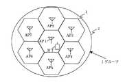
図1は、本発明の実施の形態による無線通信システムの概略的な概念図である。
図1に示すように、本実施の形態による無線通信システムは、それぞれが六角形状の7つのセル1、1、1…を含むグループ化された1つのセルグループ2を有している。
【0046】
セルグループ2は、第1アクセスポイントAP1が存在するセルと、このセルを中心としてセルの6辺のそれぞれが、他の6セルのそれぞれの1辺と接しているセル構成を有している。他の6セルのそれぞれには、第2から第7までのアクセスポイントAP2からAP7までが1セルに1アクセスポイントずつ配置されている。
【0047】
図1に示す無線通信システムにおいては、アクセスポイントAP1が存在するセルは、他の6つのアクセスポイントからの干渉信号の影響を受けると想定され、この7局が1グループとなる。この場合には、7局で順次検知信号を送信する。
その結果、7回に1回の頻度でアクセスポイントAP1の検知信号が送信される。
【0048】
図2に検知パケットの構成例を示す。図2に示すように、タイムスロットの繰返し周期において、少なくとも1つ以上のタイムスロットの中にグループ化された基地局で使う検知信号区間を用意する。ここでは、ブロードキャスト用タイムスロット3の中に、検知情報が入っている例を示している。TDMA方式による無線通信システムにおけるタイムスロットを、複数個のOFDMシンボルにより構成させ、その前半にブロードキャスト用データを割り当て、後半に各アクセスポイントAP毎に割り当てる検知信号5,6(アクセスポイントAP1又はAP2のいずれかのみから信号を出す旨の情報を含む)を割り当てる。サブキャリア毎の信号を測定するためには、最低1OFDM信号は、1つのアクセスポイントAPで占有する必要がある。
【0049】
この例では、繰り返し毎に、2アクセスポイントAPずつ順次送信しているので、3.5回で1巡することになる。他にも、1アクセスポイントAPずつ巡回し、7回の繰返し周期とすることもできる。これは、グループ化するアクセスポイントAPの数と1タイムスロットの長さ、ブロードキャストデータの長さ等から決まる検知情報に使える時間に依存する。このように、各アクセスポイントAPは周期的に自局の検知パケットを送ることができる。
端末局では、受信した信号から、この報知信号のサブキャリア毎の強度を測定する。この構成図の例を図3に示す。
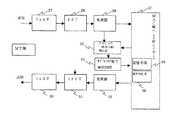
【0050】
図3(a)は、本実施の形態による無線端末(MT)の構成例を示す機能ブロック図である。図3(b)は、本実施の形態によるアクセスポイント(AP)の構成例を示す機能ブロック図である。
図3(a)に示すように、受信した信号は、アンテナ、周波数変換器等を通って、フィルタ7、FFT8、復調器9へと受信動作が行われる。この時に、ブロードキャスト検出部13において、ブロードキャストタイムスロットを検出し、この中から検知情報を抽出し、サブキャリア電力検出回路14においてサブキャリア毎の電力を測定する。これらの情報は、MAC層(上位レイヤー)17が有する記憶手段15によって7つのアクセスポイントAP分が記憶される。
【0051】
次いで、端末局(MT)では、サブキャリア毎のアクセスポイントAP1に対する干渉比となるC/(N+I)をC/(N+I)算出部16において求める。尚、この(N+I)は、熱雑音とアクセスポイントAP2からアクセスポイントAP7までの干渉を加えた非希望波(干渉波)電力である。
C/(N+I)算出部16において求められた値(検知情報)を、変調器12、IFFT(逆フーリエ変換回路)回路11、及びフィルタ10を介して送信する。
【0052】
尚、本実施の形態においては、端末(MT)側においてC/(N+I)の算出を行っているが、端末(MT)側でなく、個別の測定結果を伝送手段で受けたアクセスポイントAP1側で求めても良い。この結果から、基地局は通信に使用可能なサブキャリアを選択し通信を行う。
【0053】
図3(b)に示すように、アクセスポイント(AP)側では、端末(MT)から送られ、フィルタ18、FFT19及び復調器20を介してMAC層26中の判定回路25において、上記検知情報に基づき、いずれのサブキャリアが通信可能かを判定し通信可能なサブキャリアのみを選択する。尚、この判別は、端末機の性能とシステムで必要となるC/(N+I)に、システムマージンを加えた値を基準としている。
【0054】
判別回路25による判定結果を受けて、送信サブキャリア選択回路24において、送信するサブキャリアが選択される。加えて、判別回路25は上位層に対して1タイムスロットで送信可能な情報ビット数を通知する。これは、送信可能なビット数により、全体の必要な伝送時間が変わってくるため、上位層でのコントロールが必要となるためである。
また、端末MT側にいずれのサブキャリアに信号が載っているかを通知するためには、情報信号部分ではなく、制御信号部分にも信号を載せる必要がある。
そのための構成に関して図4を参照して説明する。
【0055】
図4に示すように、ブロードキャストパケットに個別情報27とアクセスポイントAP1,2用検知情報(アクセスポイントAP1が送信情報を出さない旨を通知する情報)とが、端末MTに転送される。端末MTでは、これらの信号に基づき復調するサブキャリアを判断する。
【0056】
尚、上記の例では、アクセスポイントAP側で送るサブキャリアを選択したが、端末MT側で選択してアクセスポイントAPに使用可能なサブキャリアを知らせることも可能である。この場合には、どのサブキャリアに信号が載っているか端末で判定する必要がなくなり、構成が容易となる。通知の方法としては、端末MT側からの制御信号を使うことができる。
従来のTDMAシステムでは、タイムスロットとして、所要C/(N+I)を満たさない場合には、通信品質が保てず、そのタイムスロットを使うことができなかった。
【0057】
これに対して、本実施の形態による無線通信技術(TDMA方式にOFDM復調方式を)適用した場合には、各々のサブキャリアが独立しており、平均電力が所定のC/(N+I)以下であっても、上述のように、各々のサブキャリアがレイリー分布に応じた電力変動を伴うので、所定のC/(N+I)を上回るサブキャリアが存在し、それを検出して通信を行えば、実際上通信可能となる。
この様子を図5(a)から図5(c)までに示した。図5は、希望波のスペクトルと、干渉波のスペクトルを示している。
【0058】
前述のように、全電力的に見ると、この希望波と干渉波とで電力差はあまりなく、全電力のC/(N+I)を指標にすると、通信できないように見える。しかしながら、図5(c)に示すように、サブキャリア毎で識別すると、所望C/(N+I)が得られるサブキャリアが多数存在することがわかる。従って、アクセスポイントAPは任意にタイムスロットを割り当てた場合でも、サブキャリアで通信が可能となる領域(fb1、fb2)が存在する。本実施の形態による無線通信技術では、アクセスポイントAPが他アクセスポイントAPからの干渉の影響を低減できるため、自局のアクセスポイントAPの判断のみによりタイムスロットを振り分けることができる。従って、無線通信システムにおける制御が容易となる。
【0059】
尚、アクセスポイントAPは、端末MTからの全タイムスロットのC/(N+I)情報を必要としない。従って、端末MTは、全タイムスロットの受信電力、或いはC/(N+I)比を測定する必要がなくなる。その結果、端末MTは全てのタイムスロットを監視することなく、自局用のタイムスロット時間のみ受信動作をすれば良く、監視に関する消費電力を大幅に下げることができるようになる。
【0060】
次に本実施の形態による無線通信システムの変形例による無線通信システムについて図面を参照して説明する。この変形例においては、上記とは異なる干渉電力算出方法を用いる。
本発明の第1の実施の形態による干渉電力の検知方法は、個別のアクセスポイントAP信号を受信することで、演算によってC/(N+I)を求める方法を用いていた。
【0061】
本発明の第1の実施の形態の変形例による方法では、巡回的に1局のみ送信しないようにする技術を用いる。かかる技術に関して図6を参照して説明する。
上述の第1の実施の形態による無線通信技術においては、多局の信号を個別に送っていたために各々を算出する必要があった。
【0062】
しかしながら、本変形例では、周期的に自局を除いた他局の信号の合成された信号(例えば領域28では、AP1を除くAP2+AP3+AP4+AP5+AP6+AP7の電力和)を送るようにした。従って、(N+I)は、この部分28の信号を測定することにより容易に算出できる。領域29では、AP2を除くAP1+AP3+AP4+AP5+AP6+AP7の電力和を送る。その後は、第1の実施の形態と同様に制御することにより、本変形例による無線通信システムにおいても、通信に使用するサブキャリアを選択することが可能となる。
【0063】
次に、本発明の第2の実施の形態による無線通信システムについて、図面を参照して説明する。
本発明の第2の実施の形態による無線通信システムは、端末がセル間を移動するハンドオフ処理に関する技術に特徴を有する。
ハンドオフ処理は、端末が移動して、アクセスポイントを次々に切替えていき、端末が無線通信システムと連続的に繋がるようにする処理である。
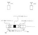
【0064】
図7に示すように、ハンドオフ処理においては、端末MT側で2つのアクセスポイントAP(AP1,AP2)からの電波の強さを比較し、ハンドオフ処理の要求を行うもの、アクセスポイントAP間で端末MTから到来する電波の強さ、遅延時間などに基づき最適なアクセスポイントAPを選定し、それに基づき無線通信システム側で指示を行うもの等がある。一般的に、ハンドオフ領域はアクセスポイントAP間の境界にある。従って、ハンドオフ領域では、双方の電波の強さの差が小さくなる。
【0065】
図7に示すように、ある距離だけ離れて設けられた2つのアクセスポイントAP1及びAP2と、移動する端末MTと、を有する無線通信システムを例にする。この無線通信システムにおいてTDMA方式の特徴であるソフトハンドオフ処理を行う場合に、2つのアクセスポイントAP1、AP2間の電力差がある閾値を下回ると、ソフトハンドオフ処理が開始される。図示するソフトハンドオフ領域においては、2つのアクセスポイントAP1、AP2と端末MTとが接続されている。
【0066】
接続元のアクセスポイントを符号AP1で、接続先のアクセスポイントを符号AP2で示すと、ソフトハンドオフ領域に入る前には、使用するタイムスロットは、アクセスポイントAP1内のみで管理されている。
一方、ソフトハンドオフ領域では、アクセスポイントAP1、アクセスポイントAP2の両方でタイムスロットが空いている必要があり、空いていない場合には、以下の方法が考えられる。
【0067】
▲1▼端末MTがソフトハンドオフに移る前に、アクセスポイントAP2からそのタイムスロットを使っていた別の端末(MT)にタイムスロット変更指示を出し、当該タイムスロットを空けさせる。
▲2▼端末MTがソフトハンドオフに移る前に、アクセスポイントAP1、アクセスポイントAP2で共通に空いているタイムスロットに、当該端末MTに変更指示を出してソフトハンドオフに移る。
【0068】
いずれかの方法で両アクセスポイントAPに共通なタイムスロットを確保できるが、この場合も第1の実施例と同様、アクセスポイントAP1、2以外のアクセスポイントAPからの干渉を計測して、空きスロットを探す必要がないので、2つのアクセスポイントAP間での整合だけであり、簡易にソフトハンドオフに移行できる。
【0069】
制御がソフトハンドオフに移行した後に、端末MTは、第1の実施の形態による無線通信システムと同様にC/(N+I)を測定するが、端末MTは、2つのアクセスポイント(基地局)と接続されているため、2つのアクセスポイントAP1、AP2のC/(N+I)情報を測定する。さらに、各サブキャリア単位で、2つのアクセスポイントAPの信号を3つの条件に選別する。
上記機能を有する端末(MT)の構成例を示す機能ブロック図を図8に示す。
【0070】
図8に示す端末は、図3に示す端末と同様に、各サブキャリアの電力を検出(検知情報検出部33、サブキャリア電力検出回路34)し、記憶(記憶手段35)するが、さらに当該2つのアクセスポイントAP1、AP2について、以下の条件1から3までのいずれに該当するかによりサブキャリアを選別する。
【0071】
条件1:アクセスポイントAP1のC/(N+I)が、アクセスポイントAP2のC/(N+I)よりも大きい。
条件2:アクセスポイントAP2のC/(N+I)が、アクセスポイントAP1のC/(N+I)より大きい。
条件3:アクセスポイントAP1とアクセスポイントAP2のC/(N+I)とが同等の大きさを有する。
【0072】
ここで、ハンドオフ処理においては、(条件1+3のサブキャリア数>条件2のサブキャリア数)の場合には、制御はアクセスポイント(基地局A)AP1のままで保持され、(条件2+3のサブキャリア数>条件1のサブキャリア数)の場合には、制御をアクセスポイント(基地局B)AP2に移す。
尚、この間の領域については、いずれのアクセスポイントが制御しても良いが、端末MTの制御が頻繁に切り替わるのを防止するため、ヒステリシスを有する状態とする、すなわち、前のアクセスポイントAPの制御下とするのが好ましい。
【0073】
従来のハンドオフにおいては、総電力だけでハンドオフを行っていたが、本実施の形態による無線通信システムにおいては、実際の通信での品質にポイントをおき、復調性能で基準となるC/(N+I)の良い方が多いアクセスポイントAPにより制御するようにするのが好ましい。
【0074】
総電力判定においては、従来、非常に電力の強いサブキャリアが1本あった場合には、全体の他のサブキャリアの特性が悪くても、それを元に判定を行ってしまう危険性があった。また、本発明の第1の実施の形態による無線通信システムでは、干渉波の影響が大きいことから、受信電力の強弱だけではデータの信頼性の判定はできなかった。
しかしながら、本発明の第2の実施の形態による無線通信システムを用いることにより、必ずC/(N+I)の良いサブキャリアが多いアクセスポイントAPを選ぶので、より正確なハンドオフ処理が可能になる。
【0075】
以上のように、本発明の各実施の形態による無線通信システムにおいては、セル構成をとり、各セルは同一の周波数を用いてTDMA方式で接続を行うセルラーシステムにおいて、通信可能なサブキャリアを用いて通信する制御を行うことで、他局からの干渉がある場合にも、通信が可能になる。
その結果、他セルとの干渉を考慮する必要がなく、自局で制御している端末局に任意にタイムスロットを割り当てることができるようになる。
【0076】
従って、制御が簡易になり、端末における全タイムスロットの監視が不要になることから、端末の低消費電力化も実現できる。
また、ソフトハンドオフ処理においても、タイムスロットの選択を接続元アクセスポイントと接続先アクセスポイントとだけにより行うことができるのでソフトハンドオフが容易に行えるようになる。
【0077】
また、サブキャリア毎に2つのアクセスポイントAP間での良否を判定できるので、より精度の良いハンドオフを行うことができるようになり、効率の良いセルラーシステム構築を行うことができる。
以上、実施の形態に沿って本発明を説明したが、本発明はこれらに制限されるものではない。その他、種々の変更、改良、組み合わせが可能なことは当業者に自明であろう。
【0078】
【発明の効果】
本発明のTDMA方式を用いた無線通信システムによれば、通信可能なサブキャリアを用いて通信する制御を行うことで、他局からの干渉がある場合にも、通信が可能になる。他のセルとの干渉を考慮する必要がなくなり、自局で制御している端末局に対して任意のタイムスロットを割り当てることができる。
【0079】
従って、制御が簡易化され、端末での全タイムスロットの監視が不要になることから、端末の低消費電力化も実現できる。
また、ソフトハンドオフにおいても、タイムスロットの選択を、接続元アクセスポイントAPと接続先アクセスポイントAPだけで行うことができるのでソフトハンドオフが容易かつ精度良くに行えるようになる。
【図面の簡単な説明】
【図1】セルラーシステムにおけるグループ化モデルを示す概念図である。
【図2】本発明の第1の実施の形態による無線通信システムにおけるブロードキャスト用タイムスロットの構成例を示す図である。
【図3】本発明の第1の実施の形態による無線通信システムに用いられる無線局であって、図3(a)は、端末局の構成を示す機能ブロック図、図3(b)はアクセスポイントの構成を示す機能ブロック図である。
【図4】本発明の第1の実施の形態による無線通信システムにおいて用いられるブロードキャスト用タイムスロットの構成例を示す図である。
【図5】本発明の第1の実施の形態による無線通信システムにおいて用いられるブロードキャスト用タイムスロットの構成例を示す図であり、図5(a)は希望波の電力スペクトル図、図5(b)は干渉波の電力スペクトル図、図5(c)は希望波と干渉波の電力スペクトルを同時に受けたときの電力スペクトルの図である。
【図6】本発明の第1の実施の形態の変形例による無線通信システムにおけるブロードキャスト用タイムスロットの構成を示す図である。
【図7】本発明の第2の実施の形態による無線通信システムにおけるソフトハンドオフの概念を示す図である。
【図8】図8は、本発明の第2の実施の形態による無線通信システムの端末局の構成を示すブロック図である。
【図9】一般的なセルラーシステムの構成を示す概念図である。
【図10】FDMAとTDMAのユーザーの使い方の違いを示す図であり、図10(a)はFDMA方式における時間−周波数軸上でのユーザの占有状況を示す図であり、図10(b)は、TDMA方式における時間−周波数軸上でのユーザの占有状況を示す図である。
【図11】TDMAシステムにおけるタイムスロットの使い方の概略を示す図である。
【図12】TDMAシステムにおけるソフトハンドオフ処理におけるタイムスロットの使用状況を示す概念図である。
【符号の説明】
1…セル、2…グループ化されたセル、AP…アクセスポイント(基地局)、MT…端末、3…タイムスロット、4…ブロードキャスト情報領域、5、6…アクセスポイント用検知情報領域、7、10…フィルタ、8…FFT、9…復調器、11…IFFT、12…変調器、13…ブロードキャスト検出部、14…サブキャリア電力検出回路、15…記憶手段、16…C/(N+I)算出部、17…上位層(MAC層)、24…送信サブキャリア選択回路、25…判定回路、27…個別情報、28、29…アクセスポイント用検知情報領域、36…条件判定部[0001]
BACKGROUND OF THE INVENTION
The present invention relates to a method capable of providing high-speed and stable communication when a cell is configured using the same frequency in a cellular system having a service area in a plane or line in a digital wireless communication system. .
[0002]
[Prior art]
In wireless systems such as mobile phones, it is necessary to cover the communication area as a wireless service, and the reach of radio waves is limited, so it is not possible to cover the service area with a single base station. Even if the terminal station moves using a base station (access point: hereinafter referred to as access point AP), communication can be continued.
[0003]
In order to realize this, a system called a cell configuration as shown in FIG. 9 is used. As shown in FIG. 9, each hexagon schematically represents a
[0004]
In such a configuration, in order to continuously perform services such as telephone calls even when the terminal MT moves, each
[0005]
However, in such a system configuration, since the frequency that can actually be used in one cell is about a fraction of the frequency allocated to the entire system, the capacity of the line that can be accommodated in the same cell is limited. .
Proposals have been made to configure cells at the same frequency using TDMA (Time Division Multiple Access). This frequency and time sharing method will be described with reference to FIG. FIG. 10A is a diagram showing the relationship between time and frequency in the FDMA (Frequency Divison Multiple Access) method, and FIG. 10B is a diagram showing the relationship between time and frequency in the TDMA method.
[0006]
As shown in FIG. 10A, in the FDMA system, different frequencies are assigned to each user, so that one user occupies the same frequency on the time axis for communication. Since there are a plurality of users in one cell, a plurality of frequency channels are assigned to each cell. For example, in
[0007]
As shown in FIG. 10B, in the TDMA system, the frequency (band) to be used is one type and is divided into fine slots on the time axis, and the user performs communication by using each slot. However, when communicating, it is necessary to repeatedly assign a slot for each user. Therefore, control is performed such as assigning a user for each period with a repetition period as one cycle.
Next, how to use a time slot when another second access point AP2 exists in a cell adjacent to the first access point AP1 will be described with reference to FIG.
[0008]
The two access points AP1 and AP2 operate as a TDMA communication system and have the same number of time slots (repetition period) and time slot time, which are the first and second access points. It is assumed that AP1 and AP2 are synchronized. FIG. 11 shows an example of a system having eight time slots TS1 to TS8.
[0009]
As shown in FIG. 11, communication is performed between the first access point AP1 and a terminal (not shown) using a second time slot TS2. Therefore, TS1 and time slots from TS3 to TS8 are vacant as time slots.
[0010]
When the second time slot TS2 is used between the second access point AP2 and the terminal, interference between the first access point AP1 and the radio wave due to communication between the terminals increases, so that the second time slot Communication is performed using any one of the time slots selected from the other seven time slots excluding the slot TS2.
Thus, by using the same frequency and dividing the time domain into a plurality of time slots, it is possible to share a frequency for communication between different access points AP.
[0011]
Further, in the conventional frequency division method, it is difficult to freely change the frequency width due to the limitation of an analog circuit such as a filter. However, if the TDMA method is used, division is possible on the time axis, so there is no circuit restriction. One terminal can use not only one time slot but also two or three time slots. In this way, the communication capacity can be doubled or tripled, and the bandwidth can be freely controlled in multimedia communication or the like.
From the above, the TDMA method is a communication method that is advantageous for packet data communication, for example, in which the transmission capacity always changes.
[0012]
[Problems to be solved by the invention]
By the way, as described above, in the TDMA communication system, when the cell configuration is adopted, the vacant state of the time slot as a minimum unit greatly affects the number of terminals that can be accommodated. When cells are assembled at the same frequency, the number of terminals that can be accommodated in the cell is determined by the number of time slots, the interference distance, and the cell arrangement.
[0013]
In wireless communication, the received power (C) to noise power (N) ratio (C / N) or received power (C) to interference power (I) ratio (C / I) required for communication is the performance of the system or terminal. If this is not satisfied, communication will be hindered. In addition, (C / (N + I)), which is an expression that takes into account both effects, may be used as an indicator of whether or not communication is possible.
[0014]
As shown in FIG. 11, the time slots that can be used in the determined time slot TS are slots whose influence of interference caused by other radio stations is equal to or less than the above formula, C / (N + I). For example, an access point AP cannot be added and assigned to a time slot that includes interference power that exceeds the allowable power.
[0015]
For this purpose, the terminal trying to connect to the access point AP measures the reception power or C / (N + I) ratio of all time slots, notifies the access point AP of the information, and the access point AP There is a need to perform control so that a time slot that is not a time slot and is an empty slot in the cell is allocated to the terminal.
[0016]
Furthermore, when performing packet communication in a TDMA system, a terminal does not occupy a time slot constantly, and an empty slot is constantly changing. Therefore, it is necessary for the terminal to constantly monitor the occupation status of all the time slots, and there is a problem in that power consumption increases because the terminal is always in the reception state.
[0017]
Further, when the number of terminals increases and the influence of interference of radio waves used in adjacent cells increases, there are cases where all the time slots cannot be used, and the terminals become busy. Therefore, there has been a problem that communication cannot be performed until the communication with other terminals is completed, the interfering station finishes communication, or the own station changes its radio wave environment due to movement or the like.
[0018]
Furthermore, there is a problem during handoff as another problem. When a terminal moves over a cell while communicating in a service area divided into cells as described above, an operation (handoff) is performed to switch an access point AP to be communicated with the terminal.
[0019]
In this handoff, a connection between a terminal and a destination access point AP is made after disconnecting the line connection with the source access point AP, and the access point AP is switched (hard handoff), and a terminal MT And the destination access point AP are connected before disconnection of the line connection with the source access point AP, and the weight of the line connection between the terminal MT and the access point AP is weighted from the source access point AP. There are two methods of gradually switching to the destination access point AP and switching the access point AP (soft handoff).
[0020]
Since the TDMA system communicates using the same frequency, the terminal MT has a feature that a soft handoff is possible in which communication can be performed simultaneously with the access point AP of the movement source and the movement destination.
In soft handoff, if the time slot used at the movement source is vacant at the movement destination among the time slots between the movement source and the destination access point AP, this time slot is allocated for soft handoff, and the terminal MT By communicating with two access points AP at the same frequency and the same time slot, it is possible to communicate with the two access points AP by emitting only one type of radio wave. Soft handoff was possible.
[0021]
FIG. 12 shows how to use the time slot in this case. The two access points AP1 and AP2 operate as a TDMA wireless communication system and have the same number of time slots (repetition period) and time slot time, and the time slot times are synchronized. FIG. 12 shows a system example having eight time slots.
[0022]
The first access point AP1 communicates with the first terminal existing in the cell of the own station using the second time slot TS2, and the second access point AP2 is in the cell of the own station. Communicating with a second terminal different from the first terminal using the sixth time slot TS6.
[0023]
Here, in the case of performing soft handoff, it is assumed that the third terminal that performs soft handoff performs communication using the fourth time slot. In this example, since the second access point AP2 does not use the fourth time slot TS4, soft handoff is possible.
[0024]
However, a third access point AP (not shown) that is adjacent to or strongly influences the second access point AP2 uses the fourth time slot TS4, and for the second access point AP2, the fourth access point AP2 The fourth time slot may not be used for communication if the influence of interference is great even though the second time slot TS4 is not used by the own station. In such a case, soft handoff cannot be performed. .
[0025]
As described above, soft handoff, which is a merit of the TDMA system, also becomes difficult to select a free time slot with less interference common to the two access points AP1 and AP2 as the density of terminals increases. .
[0026]
An object of the present invention is to provide a wireless communication system in which a terminal does not need to monitor each time slot. It is another object of the present invention to provide a technique capable of solving the situation where all time slots cannot be used and the terminal cannot communicate or cannot perform soft handoff.
[0027]
[Means for Solving the Problems]
According to an aspect of the present invention, there is provided a TDMA wireless communication system using a plurality of subcarrier modulation schemes and having at least first and second wireless stations, wherein the first wireless station is the second wireless station. The TDMA wireless communication system is characterized in that communication is performed by selectively modulating only subcarriers capable of obtaining a desired transmission rate.
[0028]
The first radio station (for example, a base station) is arbitrarily assigned to a second radio station that controls the time-divided time slot used for communication with the second radio station (for example, a terminal station). Can be assigned to.
[0029]
In the TDMA radio communication system, the second radio station has received power for each subcarrier and interference power from radio stations other than the first radio station with which the second radio station is communicating. Power detection means for detecting each subcarrier; and notification means for notifying the first wireless station of information relating to the received power and the interference power detected by the power detection means, the first radio The station selects subcarriers that select a subcarrier that can achieve a desired transmission rate in the second radio station based on the reception status and interference status of each subcarrier returned from the second radio station. And switch means that can turn on / off modulation in units of subcarriers.
[0030]
In the present invention, in a radio communication system using a multi-carrier (multi-subcarrier) modulation scheme, a cell configuration is adopted, and in a cellular system in which each cell is connected by a TDMA scheme using the same frequency, in a terminal station, By detecting the received power for each subcarrier and the interference power from other base stations other than the base station communicating with the own station for each subcarrier and notifying the base station, the base station The terminal station selects subcarriers that can achieve a desired transmission rate from the reception status and interference status for each subcarrier returned from the mobile station, and performs communication.
[0031]
As a result, it is possible to arbitrarily assign time slots to terminal stations controlled by the own station without considering interference with other cells.
In addition, as interference power detection means, the base station groups with other base stations that cause interference in its own cell area, and periodically broadcasts one station at a time and transmits a notification signal. By calculating and storing the interference power status for each subcarrier, desired signal power versus interference power can be calculated for each subcarrier.
[0032]
As another interference power detection means, the base station is grouped with other base stations that cause interference in its own cell area, and each base station has means for transmitting a notification signal at the same timing. By stopping the transmission by patroling each station, the terminal station can measure the interference power of other base stations excluding the base station communicating with its own station and calculate the desired signal power versus the interference power.
Also, in soft handoff, the terminal station creates a more accurate handoff condition reference by dividing the received power of base stations A and B and the interference power of other stations into the following conditions for each subcarrier. Can do.
[0033]
Condition 1: C / (N + I) of base station A is larger than C / (N + I) of base station B.
Condition 2: C / (N + I) of base station B is larger than C / (N + I) of base station A.
Condition 3: C / (N + I) of base station A and base station B are equivalent.
[0034]
Handoff control is
(Number of subcarriers in
In this case, the main control is performed by the base station A,
(
In this case, the main control is performed by the base station B, so that a more accurate handoff can be performed.
[0035]
DETAILED DESCRIPTION OF THE INVENTION
Before describing the embodiment of the present invention, considerations made by the inventors will be described.
The inventor uses an OFDM (Orthogonal Frequency Division Multiplex) scheme as a modulation scheme in a radio communication system using a TDMA scheme as a multiplexing scheme, and an access point (first radio station) and a terminal station (second radio station). I thought of the possibility that wireless communication can be continued even if the time slot used by the wireless communication station and the time slot used by another wireless station adjacent to the wireless communication station are the same time slot.
This point will be described in more detail with reference to FIGS. 5 (a) to 5 (c).
[0036]
FIG. 5A is a graph showing a spectrum of a desired wave (a signal actually used for wireless communication), where the vertical axis represents power and the horizontal axis represents frequency. When this entire spectrum is considered as a composite desired wave, this spectrum has an average power value that is defined by a broken line indicated by a symbol MVD and does not depend on a frequency.
[0037]
FIG. 5B is a graph showing a spectrum of an interference wave (a signal entering due to other wireless communication). When this entire spectrum is considered as a combined interference wave, this spectrum has an average power value that is defined by a broken line indicated by a symbol MVI and does not depend on a frequency.
[0038]
When there is no difference in power value between the combined desired wave shown in FIG. 5 (a) and the combined interference wave shown in FIG. 5 (b) (such as when two wireless communication bodies are close to each other), at any frequency There is no difference in power value between the combined desired wave and the combined interference wave. Therefore, communication cannot be performed using the same time slot.
[0039]
However, in practice, as shown in FIG. 5A, the spectrum of the desired wave modulated by the OFDM method can be expressed as a composite wave of a number of subcarriers. Each subcarrier has a time variation according to the Rayleigh distribution due to fading. That is, the power value varies with time.
[0040]
The inventor considered that the spectrum (relationship between power and frequency) of a desired wave and an interference wave at a certain time is as shown in FIG. As shown in FIG. 5 (c), in a subcarrier unit and at a certain time, the power of the desired wave greatly exceeds the power intensity of the interference wave (the interference wave can be ignored) (in FIG. 5 (c)). It is considered that fb1 and fb2) exist. In other words, in the frequency bands fb1 and fb2, the influence of the interference wave can be ignored even if the same time slot is used. Therefore, in communication between radio stations, there is a possibility that different transmission / reception processes can be performed in the same time slot. is there.
[0041]
Further, the inventor is provided with means for detecting the frequency bands fb1 and fb2 shown in FIG. 5C, and if transmission / reception processing is performed using only this frequency band (subcarrier), different transmission / reception processing is performed in the same time slot. I thought it could be done reliably.
Based on the above considerations, embodiments of the present invention will be described below.
First, the radio | wireless communications system by the 1st Embodiment of this invention is demonstrated, referring drawings.
[0042]
A case where a terminal is also present in a cell where an access point is present will be described. A terminal is connected to a network as a communication system by communicating with an access point. For this purpose, it is necessary to determine a time slot for communicating with the access point.
[0043]
In the present invention, as time slots for communication with terminals, time slots that are not assigned to other terminals in the own station among all time slots prepared by the system for the access point are freely assigned. Can do.
For example, the access point periodically transmits a detection signal for the terminal to measure the strength of the signal of the access point and compare it with the strength of the interference signal.
[0044]
Such a detection signal needs to be transmitted by all access points. Therefore, for example, the frequency at which the access point AP1 issues the detection signal is changed according to the number of grouped access points AP that include the cell of the access point AP1 and that interference is expected to reach the cell. It is configured.
[0045]
FIG. 1 is a schematic conceptual diagram of a radio communication system according to an embodiment of the present invention.
As shown in FIG. 1, the radio communication system according to the present embodiment has one
[0046]
The
[0047]
In the wireless communication system shown in FIG. 1, the cell in which the access point AP1 exists is assumed to be affected by interference signals from the other six access points, and these seven stations form one group. In this case, the detection signals are sequentially transmitted from the seven stations.
As a result, the detection signal of the access point AP1 is transmitted once every seven times.
[0048]
FIG. 2 shows a configuration example of the detection packet. As shown in FIG. 2, in the repetition period of time slots, detection signal sections are prepared for use by base stations grouped in at least one or more time slots. In this example, detection information is included in the broadcast time slot 3. A time slot in a wireless communication system based on the TDMA scheme is composed of a plurality of OFDM symbols, broadcast data is assigned to the first half, and
[0049]
In this example, since two access points AP are sequentially transmitted every repetition, one round is made in 3.5 times. Alternatively, the access point AP can be circulated one by one, and the repetition cycle can be made seven times. This depends on the time available for detection information determined from the number of access points AP to be grouped, the length of one time slot, the length of broadcast data, and the like. In this way, each access point AP can periodically send its own detection packet.
The terminal station measures the strength of each broadcast signal for each subcarrier from the received signal. An example of this configuration diagram is shown in FIG.
[0050]
FIG. 3A is a functional block diagram showing a configuration example of the wireless terminal (MT) according to the present embodiment. FIG. 3B is a functional block diagram illustrating a configuration example of the access point (AP) according to the present embodiment.
As shown in FIG. 3A, the received signal passes through an antenna, a frequency converter, etc., and is received by the filter 7, the FFT 8, and the demodulator 9. At this time, the
[0051]
Next, in the terminal station (MT), C / (which becomes an interference ratio with respect to the access point AP1 for each subcarrier.N + I ) In the C / (N + I)
The value (detection information) obtained by the C / (N + I)
[0052]
In this embodiment, C / (N + I) is calculated on the terminal (MT) side, but not on the terminal (MT) side, but on the access point AP1 side that receives the individual measurement results by the transmission means. You may ask for it. From this result, the base station performs communication by selecting a subcarrier that can be used for communication.
[0053]
As shown in FIG. 3B, on the access point (AP) side, the detection information is sent from the terminal (MT) and received by the
[0054]
In response to the determination result by the
Further, in order to notify the terminal MT side of which subcarrier is carrying the signal, it is necessary to place the signal not on the information signal part but also on the control signal part.
A configuration for this will be described with reference to FIG.
[0055]
As shown in FIG. 4, the
[0056]
In the above example, the subcarrier to be transmitted is selected on the access point AP side. However, it is also possible to select on the terminal MT side to notify the access point AP of usable subcarriers. In this case, it is not necessary for the terminal to determine which subcarrier carries the signal, and the configuration becomes easy. As a notification method, a control signal from the terminal MT side can be used.
In the conventional TDMA system, when the required C / (N + I) is not satisfied as a time slot, the communication quality cannot be maintained and the time slot cannot be used.
[0057]
On the other hand, when the radio communication technique according to the present embodiment (OFDM demodulation scheme is applied to the TDMA scheme), each subcarrier is independent, and the average power is less than or equal to a predetermined C / (N + I). Even if, as described above, each subcarrier is accompanied by power fluctuations according to the Rayleigh distribution, there is a subcarrier exceeding a predetermined C / (N + I), and if it is detected and communication is performed, In practice, communication is possible.
This state is shown in FIGS. 5A to 5C. FIG. 5 shows the spectrum of the desired wave and the spectrum of the interference wave.
[0058]
As described above, when viewed in terms of total power, there is not much power difference between the desired wave and the interference wave, and when C / (N + I) of the total power is used as an index, it seems that communication is not possible. However, as shown in FIG. 5 (c), it can be seen that there are many subcarriers from which desired C / (N + I) can be obtained by identifying each subcarrier. Therefore, even when the access point AP arbitrarily assigns time slots, there are areas (fb1, fb2) where communication is possible with subcarriers. In the wireless communication technique according to the present embodiment, since the access point AP can reduce the influence of interference from other access points AP, time slots can be allocated only by the determination of the access point AP of the local station. Therefore, control in the wireless communication system is facilitated.
[0059]
Note that the access point AP does not need C / (N + I) information of all time slots from the terminal MT. Accordingly, the terminal MT does not need to measure the reception power or C / (N + I) ratio of all time slots. As a result, the terminal MT only needs to perform the reception operation for the own time slot time without monitoring all the time slots, and the power consumption related to monitoring can be greatly reduced.
[0060]
Next, a radio communication system according to a modification of the radio communication system according to the present embodiment will be described with reference to the drawings. In this modification, an interference power calculation method different from the above is used.
The method for detecting interference power according to the first embodiment of the present invention uses a method of obtaining C / (N + I) by calculation by receiving an individual access point AP signal.
[0061]
In the method according to the modification of the first embodiment of the present invention, a technique is used in which only one station is not transmitted cyclically. This technique will be described with reference to FIG.
In the wireless communication technique according to the first embodiment described above, since signals from multiple stations are individually transmitted, it is necessary to calculate each of them.
[0062]
However, in this modification, a signal obtained by periodically combining signals from other stations excluding the own station (for example, in the
[0063]
Next, the radio | wireless communications system by the 2nd Embodiment of this invention is demonstrated with reference to drawings.
The radio communication system according to the second embodiment of the present invention is characterized by a technique related to handoff processing in which a terminal moves between cells.
The handoff process is a process for moving the terminal and switching access points one after another so that the terminal is continuously connected to the wireless communication system.
[0064]
As shown in FIG. 7, in handoff processing, the terminal MT side compares the strength of radio waves from two access points AP (AP1, AP2) and requests handoff processing. There are those that select an optimal access point AP based on the strength of radio waves coming from the MT, delay time, etc., and give instructions on the wireless communication system side based on the AP. In general, the handoff region is at the boundary between access points AP. Therefore, in the handoff region, the difference between the two radio wave strengths is small.
[0065]
As shown in FIG. 7, a wireless communication system having two access points AP1 and AP2 provided at a certain distance and a moving terminal MT is taken as an example. When performing soft handoff processing, which is a feature of the TDMA scheme, in this wireless communication system, if the power difference between the two access points AP1 and AP2 falls below a certain threshold, the soft handoff processing is started. In the illustrated soft handoff region, two access points AP1, AP2 and a terminal MT are connected.
[0066]
When the access point of the connection source is denoted by reference character AP1 and the access point of the connection destination is denoted by reference symbol AP2, the time slot to be used is managed only within the access point AP1 before entering the soft handoff region.
On the other hand, in the soft handoff region, it is necessary that both the access point AP1 and the access point AP2 have a free time slot.
[0067]
{Circle around (1)} Before the terminal MT shifts to the soft handoff, the access point AP2 issues a time slot change instruction to another terminal (MT) that has used the time slot, thereby freeing the time slot.
{Circle around (2)} Before the terminal MT shifts to soft handoff, a change instruction is issued to the terminal MT in a time slot that is vacant in common at the access point AP1 and access point AP2, and shifts to soft handoff.
[0068]
Although either method can secure a time slot common to both access points AP, in this case as well, as in the first embodiment, the interference from access points AP other than access points AP1 and AP2 is measured, and an empty slot is obtained. Since there is no need to search for this, only the matching between the two access points AP is possible, and the transition to soft handoff can be easily performed.
[0069]
After the control shifts to soft handoff, the terminal MT measures C / (N + I) as in the wireless communication system according to the first embodiment, but the terminal MT is connected to two access points (base stations). Therefore, the C / (N + I) information of the two access points AP1 and AP2 is measured. Furthermore, the signals of the two access points AP are sorted into three conditions for each subcarrier.
FIG. 8 shows a functional block diagram illustrating a configuration example of a terminal (MT) having the above functions.
[0070]
The terminal shown in FIG. 8 detects the power of each subcarrier (detection
[0071]
Condition 1: C / (N + I) of access point AP1 is larger than C / (N + I) of access point AP2.
Condition 2: C / (N + I) of access point AP2 is larger than C / (N + I) of access point AP1.
Condition 3: C / (N + I) of the access point AP1 and the access point AP2 have the same size.
[0072]
Here, in the handoff process, in the case of (number of subcarriers in
Note that any access point may control the area during this period, but in order to prevent frequent switching of the control of the terminal MT, a state having hysteresis is set, that is, control of the previous access point AP. It is preferable to use the following.
[0073]
In the conventional handoff, handoff is performed only with the total power. However, in the radio communication system according to the present embodiment, the quality in actual communication is pointed, and C / (N + I) which is a reference in demodulation performance. It is preferable to control by the access point AP, which has the better one.
[0074]
In the total power determination, conventionally, when there is one very strong subcarrier, there is a risk that the determination may be made based on that even if the characteristics of the other subcarriers are poor. It was. Further, in the wireless communication system according to the first embodiment of the present invention, since the influence of interference waves is large, the reliability of data cannot be determined only by the strength of received power.
However, by using the wireless communication system according to the second embodiment of the present invention, an access point AP having a large number of subcarriers with good C / (N + I) is always selected, so that more accurate handoff processing can be performed.
[0075]
As described above, in the radio communication system according to each embodiment of the present invention, a subcarrier that can be communicated is used in a cellular system that has a cell configuration and each cell is connected by the TDMA method using the same frequency. By performing communication control, communication is possible even when there is interference from other stations.
As a result, there is no need to consider interference with other cells, and time slots can be arbitrarily allocated to terminal stations controlled by the own station.
[0076]
Therefore, the control is simplified and it is not necessary to monitor all the time slots in the terminal, so that the power consumption of the terminal can be reduced.
Also in the soft handoff process, since the time slot can be selected only by the connection source access point and the connection destination access point, soft handoff can be easily performed.
[0077]
Moreover, since the pass / fail between two access points AP can be determined for each subcarrier, a more accurate handoff can be performed, and an efficient cellular system can be constructed.
As mentioned above, although this invention was demonstrated along embodiment, this invention is not restrict | limited to these. It will be apparent to those skilled in the art that other various modifications, improvements, and combinations can be made.
[0078]
【The invention's effect】
According to the wireless communication system using the TDMA system of the present invention, communication can be performed even when there is interference from other stations by performing communication control using communicable subcarriers. There is no need to consider interference with other cells, and an arbitrary time slot can be assigned to a terminal station controlled by the own station.
[0079]
Accordingly, the control is simplified, and since it is not necessary to monitor all the time slots at the terminal, the power consumption of the terminal can be reduced.
Also in the soft handoff, the time slot can be selected only by the connection source access point AP and the connection destination access point AP, so that the soft handoff can be performed easily and accurately.
[Brief description of the drawings]
FIG. 1 is a conceptual diagram showing a grouping model in a cellular system.
FIG. 2 is a diagram illustrating a configuration example of a broadcast time slot in the wireless communication system according to the first embodiment of the present invention.
3A and 3B are radio stations used in the radio communication system according to the first embodiment of the present invention. FIG. 3A is a functional block diagram showing the configuration of a terminal station, and FIG. It is a functional block diagram which shows the structure of a point.
FIG. 4 is a diagram illustrating a configuration example of a broadcast time slot used in the wireless communication system according to the first embodiment of the present invention.
FIG. 5 is a diagram showing a configuration example of a broadcast time slot used in the wireless communication system according to the first embodiment of the present invention, FIG. 5 (a) is a power spectrum diagram of a desired wave, and FIG. ) Is a power spectrum diagram of the interference wave, and FIG. 5C is a diagram of the power spectrum when the power spectrum of the desired wave and the interference wave is received simultaneously.
FIG. 6 is a diagram showing a structure of a broadcast time slot in a wireless communication system according to a modification of the first embodiment of the present invention.
FIG. 7 is a diagram showing a concept of soft handoff in a wireless communication system according to a second embodiment of the present invention.
FIG. 8 is a block diagram showing a configuration of a terminal station of a wireless communication system according to a second embodiment of the present invention.
FIG. 9 is a conceptual diagram showing a configuration of a general cellular system.
10 is a diagram illustrating a difference in usage between FDMA and TDMA users, and FIG. 10A is a diagram illustrating a user occupation state on a time-frequency axis in the FDMA scheme; FIG. These are the figures which show the occupation state of the user on the time-frequency axis in a TDMA system.
FIG. 11 is a diagram showing an outline of how to use time slots in a TDMA system.
FIG. 12 is a conceptual diagram showing a usage state of time slots in soft handoff processing in a TDMA system.
[Explanation of symbols]
DESCRIPTION OF
Claims (7)
Translated fromJapanese前記第2の無線局は、サブキャリア毎の受信電力と、前記第2の無線局が通信している前記第1の無線局以外の無線局からの干渉電力とをサブキャリア毎に検知する電力検知手段と、該電力検知手段により検知された前記受信電力と前記干渉電力に関する情報から、所要C/(N+I)を満たすサブキャリアを前記第1の無線局に通知する通知手段とを有し、
前記第1の無線局は、サブキャリア単位で変調をオン/オフできるスイッチ手段を有し、前記第2の無線局からの通知に基づいて、前記所要C/(N+I)を満たすサブキャリアのみを前記スイッチ手段を用いて変調して前記第2の無線局に送信するTDMA無線通信システム。A TDMA wireless communication system using a plurality of subcarrier modulation schemes and having at least first and second wireless stations,
The second radio station detects, for each subcarrier, received power for each subcarrier and interference power from radio stations other than the first radio station with which the second radio station is communicating. Detection means, and notification means for notifying the first radio station of asubcarrier satisfying the required C / (N + I) from the information on the received power and the interference power detected by the power detection means,
The first radio stationhas a switch manuallystage can be turned on / off modulated bysubcarrierbasis, based on the notification from the second radio station, only the sub-carrier satisfying the required C / (N + I) A TDMA wireless communication systemthat modulates the signal using the switch means and transmits the modulated signal to the second wireless station .
前記第1の無線局が、自己の通信エリア内で干渉を与える他の第1の無線局とともにグループ化され、該グループ化された前記第1の無線局が順次1局ずつ報知信号を送信した際に、前記第2の無線局が、それぞれの前記第2の無線局のサブキャリア毎にその干渉電力状況を抽出又は算出する干渉電力判定手段と、その値を記憶する記憶手段と、サブキャリア毎に希望波電力と干渉電力との比を算出する演算手段とを含む請求項1に記載のTDMA無線通信システム。The power detection means is
The first radio stations are grouped together with other first radio stations that cause interference in their own communication area, and the grouped first radio stations sequentially transmit notification signals one by one. In this case, the second radio station extracts or calculates the interference power status for each subcarrier of the second radio station, storage means for storing the value, subcarrier, The TDMA wireless communication system according to claim1 , further comprising computing means for calculating a ratio of desired wave power and interference power for each.
前記第1の無線局が、自己の通信エリア内で干渉を与える他の第1の無線局とともにグループ化され、該グループ化された前記第1の無線局のそれぞれは、同一タイミングで報知信号を送信し、順次定期的に1局ずつ巡回して送信を止めた際に、前記第2の無線局が、自己と通信している前記第1の無線局を除いた他の第1の無線局の干渉電力をサブキャリア毎に測定する干渉電力測定手段と、サブキャリア毎に希望波電力と干渉電力との比を算出する演算手段とを含む請求項1に記載のTDMA無線通信システム。BeforeSymbol power detection means,
The first wireless stations are grouped together with other first wireless stations that cause interference in their communication areas, and each of the grouped first wireless stations transmits a notification signal at the same timing. The first wireless station other than the first wireless station that the second wireless station is communicating with itself when the transmission is stopped and the transmission is stopped sequentially and periodically The TDMA wireless communication system according to claim1 , further comprising: interference power measuring means for measuring the interference power of each subcarrier; and arithmetic means for calculating a ratio between desired wave power and interference power for each subcarrier.
前記第2の無線局は、サブキャリア毎の受信電力と、前記第2の無線局が通信している前記第1の無線局以外の無線局からの干渉電力とをサブキャリア毎に検知する電力検知手段と、該電力検知手段により検知された前記受信電力と前記干渉電力に関する情報を前記第1の無線局に通知する通知手段とを有し、前記第1の無線局は、前記第2の無線局から返信されたサブキャリア毎の受信状況と干渉状況とに基づいて、前記第2の無線局において所望の伝送レートを達成できるサブキャリアを選択するサブキャリア選択手段とサブキャリア単位で変調をオン/オフできるスイッチ手段とを有しており、
前記電力検知手段は、前記第1の無線局が、自己の通信エリア内で干渉を与える他の第1の無線局とともにグループ化され、該グループ化された前記第1の無線局が順次1局ずつ報知信号を送信した際に、前記第2の無線局が、それぞれの前記第2の無線局のサブキャリア毎にその干渉電力状況を抽出又は算出する干渉電力判定手段と、その値を記憶する記憶手段と、サブキャリア毎に希望波電力と干渉電力との比を算出する演算手段とを含むTDMA無線通信システム。A TDMA radio communication system using a plurality of subcarrier modulation schemes and having at least first and second radio stations, wherein the first radio station can obtain a desired transmission rate in the second radio station. In a TDMA wireless communication system characterized by performing communication by selectively modulating only a carrier,
The second radio station detects, for each subcarrier, received power for each subcarrier and interference power from radio stations other than the first radio station with which the second radio station is communicating. Detection means, and notification means for notifying the first wireless station of information related to the received power and the interference power detected by the power detection means, wherein the first wireless station is configured to receive the second wireless station. Based on the reception status and interference status for each subcarrier returned from the radio station, subcarrier selection means for selecting a subcarrier capable of achieving a desired transmission rate in the second radio station and modulation in subcarrier units. Switch means that can be turned on / off,
In the power detection means, the first wireless stations are grouped together with other first wireless stations that cause interference in their own communication areas, and the grouped first wireless stations are sequentially one station When the broadcast signal is transmitted one by one, the second radio station extracts the interference power status for each subcarrier of each second radio station, and stores the value memory means and arithmetic means and theincluding T DMA wireless communication system for calculating a ratio between desired wave power and the interference power for each subcarrier.
前記第2の無線局は、サブキャリア毎の受信電力と、前記第2の無線局が通信している前記第1の無線局以外の無線局からの干渉電力とをサブキャリア毎に検知する電力検知手段と、該電力検知手段により検知された前記受信電力と前記干渉電力に関する情報を前記第1の無線局に通知する通知手段とを有し、前記第1の無線局は、前記第2の無線局から返信されたサブキャリア毎の受信状況と干渉状況とに基づいて、前記第2の無線局において所望の伝送レートを達成できるサブキャリアを選択するサブキャリア選択手段とサブキャリア単位で変調をオン/オフできるスイッチ手段とを有しており、
前記電力検知手段は、前記第1の無線局が、自己の通信エリア内で干渉を与える他の第1の無線局とともにグループ化され、該グループ化された前記第1の無線局のそれぞれは、同一タイミングで報知信号を送信し、順次定期的に1局ずつ巡回して送信を止めた際に、前記第2の無線局が、自己と通信している前記第1の無線局を除いた他の第1の無線局の干渉電力をサブキャリア毎に測定する干渉電力測定手段と、サブキャリア毎に希望波電力と干渉電力との比を算出する演算手段とを含むTDMA無線通信システム。A TDMA radio communication system using a plurality of subcarrier modulation schemes and having at least first and second radio stations, wherein the first radio station canobtain adesired transmissionratein the second radio station.In a TDMA wireless communication system characterized by performing communication by selectively modulating only a carrier,
The second radio station detects, for each subcarrier, received power for each subcarrier and interference power from radio stations other than the first radio station with which the second radio station is communicating. Detection means, and notification means for notifying the first wireless station of information related to the received power and the interference power detected by the power detection means, wherein the first wireless station is configured to receive the second wireless station. Based on the reception status and interference status for each subcarrier returned from the radio station, subcarrier selection means for selecting a subcarrier capable of achieving a desired transmission rate in the second radio station and modulation in subcarrier units. Switch means that can be turned on / off,
BeforeSymbol power it detecting means, wherein the first radio station are grouped with other of the first radio station that causes interference within the self-communication area, each of said being said grouped first radio station Transmits the notification signal at the same timing, and periodically stops the transmission by periodically pausing one station at a time, except for the first wireless station that is communicating with itself. and other interference power measuring means for interference power of the first radio station is measured for each subcarrier, the desired signal power and the ratioincluding T DMA wireless communication and a computing means for calculating the interference power for each subcarrier system.
サブキャリア毎の受信電力と、前記第2の無線局が通信している前記第1の無線局以外の無線局からの干渉電力とをサブキャリア毎に検知する電力検知手段と、該電力検知手段により検知された前記受信電力と前記干渉電力に関する情報から、所要C/(N+I)を満たすサブキャリアを、前記第1の無線局に通知する通知手段とを有し、サブキャリア単位で変調をオン/オフできるスイッチ手段を有する前記第1の無線局に対して、前記第2の無線局からの通知に基づいて、前記所要C/(N+I)を満たすサブキャリアのみを前記スイッチ手段を用いて変調して前記第2の無線局に送信するように促すことを特徴とする第2の無線局。Used in a TDMA wireless communication systemusing a plurality of subcarrier modulation schemes and having at least first and second wireless stations,
Power detection means for detecting reception power for each subcarrier and interference power from a radio station other than the first radio station with which the second radio station is communicating; and the power detection means Anda notification means for notifying the first radio station of a subcarrier satisfying the required C / (N + I) from the information on the received power and the interference power detected by thetransmitter, and turns on the modulation on a subcarrier basis. Based on the notification from the second radio station, only the subcarriers satisfying the required C / (N + I) are modulated using the switch means with respect to the first radio station having the switch means that can be turned off / off. Then, the second radio station is urged to transmit to the second radio station.
サブキャリア毎の受信電力と、前記第2の無線局が通信している前記第1の無線局以外の無線局からの干渉電力と、をサブキャリア毎に検知し、検知された前記受信電力と前記干渉電力に関する情報から所要C/(N+I)を満たすサブキャリアに関する前記第2の無線局からの通知に基づいて、サブキャリア単位で変調をオン/オフできるスイッチ手段により、前記所要C/(N+I)を満たすサブキャリアのみを前記スイッチ手段を用いて変調して前記第2の無線局に送信することを特徴とする第1の無線局。Used in a TDMA wireless communication systemusing a plurality of subcarrier modulation schemes and having at least first and second wireless stations,
The received power for each subcarrier and the interference power from radio stations other than the first radio station with which the second radio station is communicating are detected for each subcarrier, and the detected received power isBased on the notification from the second radio stationregarding the subcarrier satisfying the required C / (N + I) from the information on the interference power, the required C / (N + I) is providedby switch means capable of turning on / off the modulation in units of subcarriers. The first radio stationis characterized in that only the subcarriers satisfying (2) are modulated using the switch means and transmitted to the second radio station.
Priority Applications (7)
| Application Number | Priority Date | Filing Date | Title |
|---|---|---|---|
| JP2002064925AJP3898533B2 (en) | 2002-03-11 | 2002-03-11 | Wireless communication system |
| EP03705284AEP1489868A4 (en) | 2002-03-11 | 2003-02-18 | Radio communication system |
| AU2003211440AAU2003211440A1 (en) | 2002-03-11 | 2003-02-18 | Radio communication system |
| KR1020047014040AKR100655237B1 (en) | 2002-03-11 | 2003-02-18 | Radio communication system |
| US10/507,068US7447169B2 (en) | 2002-03-11 | 2003-02-18 | Radio communication system |
| CNB038057107ACN100539751C (en) | 2002-03-11 | 2003-02-18 | wireless communication system |
| PCT/JP2003/001719WO2003077578A1 (en) | 2002-03-11 | 2003-02-18 | Radio communication system |
Applications Claiming Priority (1)
| Application Number | Priority Date | Filing Date | Title |
|---|---|---|---|
| JP2002064925AJP3898533B2 (en) | 2002-03-11 | 2002-03-11 | Wireless communication system |
Publications (2)
| Publication Number | Publication Date |
|---|---|
| JP2003264876A JP2003264876A (en) | 2003-09-19 |
| JP3898533B2true JP3898533B2 (en) | 2007-03-28 |
Family
ID=27800224
Family Applications (1)
| Application Number | Title | Priority Date | Filing Date |
|---|---|---|---|
| JP2002064925AExpired - Fee RelatedJP3898533B2 (en) | 2002-03-11 | 2002-03-11 | Wireless communication system |
Country Status (7)
| Country | Link |
|---|---|
| US (1) | US7447169B2 (en) |
| EP (1) | EP1489868A4 (en) |
| JP (1) | JP3898533B2 (en) |
| KR (1) | KR100655237B1 (en) |
| CN (1) | CN100539751C (en) |
| AU (1) | AU2003211440A1 (en) |
| WO (1) | WO2003077578A1 (en) |
Families Citing this family (66)
| Publication number | Priority date | Publication date | Assignee | Title |
|---|---|---|---|---|
| US7239622B2 (en)* | 2002-09-19 | 2007-07-03 | Qualcomm Incorporated | Modified scheduling technique for a telecommunication system |
| JP2005167502A (en)* | 2003-12-01 | 2005-06-23 | Ntt Docomo Inc | Radio communication system, transmitting radio station control apparatus, receiving radio station control apparatus, and subcarrier selection method |
| JP4440739B2 (en) | 2004-09-06 | 2010-03-24 | 株式会社エヌ・ティ・ティ・ドコモ | Frequency sharing type transmitter |
| JP4558452B2 (en)* | 2004-11-09 | 2010-10-06 | パナソニック株式会社 | Multi-carrier communication apparatus and cell selection method |
| JP2006157217A (en)* | 2004-11-26 | 2006-06-15 | Nec Corp | Apparatus for cell reselection, mobile communication terminal, method for cell reselection, program and recording medium |
| KR100696401B1 (en)* | 2004-11-29 | 2007-03-19 | 연세대학교 산학협력단 | Subcarrier Handover Method and System in Mobile Communication System Using Multiple Carriers |
| US20070002724A1 (en)* | 2005-06-15 | 2007-01-04 | Samsung Electronics Co., Ltd. | Apparatus and method for broadcast superposition and cancellation in a multi-carrier wireless network |
| US7894818B2 (en)* | 2005-06-15 | 2011-02-22 | Samsung Electronics Co., Ltd. | Apparatus and method for multiplexing broadcast and unicast traffic in a multi-carrier wireless network |
| KR100716269B1 (en)* | 2006-03-27 | 2007-05-10 | 연세대학교 산학협력단 | Handover Method in Multi-carrier Based Mobile Communication System and Mobile Communication Terminal for the Same |
| US20100232296A1 (en)* | 2006-05-25 | 2010-09-16 | Mitsubishi Electric Corporation | Mobile communication system |
| US9191799B2 (en)* | 2006-06-09 | 2015-11-17 | Juniper Networks, Inc. | Sharing data between wireless switches system and method |
| US7765294B2 (en) | 2006-06-30 | 2010-07-27 | Embarq Holdings Company, Llc | System and method for managing subscriber usage of a communications network |
| US8000318B2 (en) | 2006-06-30 | 2011-08-16 | Embarq Holdings Company, Llc | System and method for call routing based on transmission performance of a packet network |
| US8194643B2 (en) | 2006-10-19 | 2012-06-05 | Embarq Holdings Company, Llc | System and method for monitoring the connection of an end-user to a remote network |
| US8289965B2 (en) | 2006-10-19 | 2012-10-16 | Embarq Holdings Company, Llc | System and method for establishing a communications session with an end-user based on the state of a network connection |
| US8717911B2 (en) | 2006-06-30 | 2014-05-06 | Centurylink Intellectual Property Llc | System and method for collecting network performance information |
| US7948909B2 (en) | 2006-06-30 | 2011-05-24 | Embarq Holdings Company, Llc | System and method for resetting counters counting network performance information at network communications devices on a packet network |
| US9094257B2 (en) | 2006-06-30 | 2015-07-28 | Centurylink Intellectual Property Llc | System and method for selecting a content delivery network |
| US8488447B2 (en) | 2006-06-30 | 2013-07-16 | Centurylink Intellectual Property Llc | System and method for adjusting code speed in a transmission path during call set-up due to reduced transmission performance |
| JP4978084B2 (en)* | 2006-07-05 | 2012-07-18 | 日本電気株式会社 | Cellular system, frequency carrier allocation method thereof, base station controller and base station used therefor |
| US8040811B2 (en) | 2006-08-22 | 2011-10-18 | Embarq Holdings Company, Llc | System and method for collecting and managing network performance information |
| US7889660B2 (en)* | 2006-08-22 | 2011-02-15 | Embarq Holdings Company, Llc | System and method for synchronizing counters on an asynchronous packet communications network |
| US8576722B2 (en) | 2006-08-22 | 2013-11-05 | Centurylink Intellectual Property Llc | System and method for modifying connectivity fault management packets |
| US9479341B2 (en) | 2006-08-22 | 2016-10-25 | Centurylink Intellectual Property Llc | System and method for initiating diagnostics on a packet network node |
| US7940735B2 (en) | 2006-08-22 | 2011-05-10 | Embarq Holdings Company, Llc | System and method for selecting an access point |
| US8307065B2 (en) | 2006-08-22 | 2012-11-06 | Centurylink Intellectual Property Llc | System and method for remotely controlling network operators |
| US8537695B2 (en) | 2006-08-22 | 2013-09-17 | Centurylink Intellectual Property Llc | System and method for establishing a call being received by a trunk on a packet network |
| US8107366B2 (en) | 2006-08-22 | 2012-01-31 | Embarq Holdings Company, LP | System and method for using centralized network performance tables to manage network communications |
| US8743703B2 (en) | 2006-08-22 | 2014-06-03 | Centurylink Intellectual Property Llc | System and method for tracking application resource usage |
| US8064391B2 (en) | 2006-08-22 | 2011-11-22 | Embarq Holdings Company, Llc | System and method for monitoring and optimizing network performance to a wireless device |
| US8223655B2 (en) | 2006-08-22 | 2012-07-17 | Embarq Holdings Company, Llc | System and method for provisioning resources of a packet network based on collected network performance information |
| US8125897B2 (en) | 2006-08-22 | 2012-02-28 | Embarq Holdings Company Lp | System and method for monitoring and optimizing network performance with user datagram protocol network performance information packets |
| US8015294B2 (en) | 2006-08-22 | 2011-09-06 | Embarq Holdings Company, LP | Pin-hole firewall for communicating data packets on a packet network |
| US8274905B2 (en) | 2006-08-22 | 2012-09-25 | Embarq Holdings Company, Llc | System and method for displaying a graph representative of network performance over a time period |
| US8549405B2 (en) | 2006-08-22 | 2013-10-01 | Centurylink Intellectual Property Llc | System and method for displaying a graphical representation of a network to identify nodes and node segments on the network that are not operating normally |
| US8407765B2 (en) | 2006-08-22 | 2013-03-26 | Centurylink Intellectual Property Llc | System and method for restricting access to network performance information tables |
| US8531954B2 (en) | 2006-08-22 | 2013-09-10 | Centurylink Intellectual Property Llc | System and method for handling reservation requests with a connection admission control engine |
| US7808918B2 (en) | 2006-08-22 | 2010-10-05 | Embarq Holdings Company, Llc | System and method for dynamically shaping network traffic |
| US8224255B2 (en) | 2006-08-22 | 2012-07-17 | Embarq Holdings Company, Llc | System and method for managing radio frequency windows |
| US8130793B2 (en) | 2006-08-22 | 2012-03-06 | Embarq Holdings Company, Llc | System and method for enabling reciprocal billing for different types of communications over a packet network |
| US8144587B2 (en) | 2006-08-22 | 2012-03-27 | Embarq Holdings Company, Llc | System and method for load balancing network resources using a connection admission control engine |
| US8102770B2 (en) | 2006-08-22 | 2012-01-24 | Embarq Holdings Company, LP | System and method for monitoring and optimizing network performance with vector performance tables and engines |
| US7684332B2 (en) | 2006-08-22 | 2010-03-23 | Embarq Holdings Company, Llc | System and method for adjusting the window size of a TCP packet through network elements |
| US8619600B2 (en) | 2006-08-22 | 2013-12-31 | Centurylink Intellectual Property Llc | System and method for establishing calls over a call path having best path metrics |
| US8199653B2 (en) | 2006-08-22 | 2012-06-12 | Embarq Holdings Company, Llc | System and method for communicating network performance information over a packet network |
| US7843831B2 (en) | 2006-08-22 | 2010-11-30 | Embarq Holdings Company Llc | System and method for routing data on a packet network |
| US8228791B2 (en) | 2006-08-22 | 2012-07-24 | Embarq Holdings Company, Llc | System and method for routing communications between packet networks based on intercarrier agreements |
| US8098579B2 (en) | 2006-08-22 | 2012-01-17 | Embarq Holdings Company, LP | System and method for adjusting the window size of a TCP packet through remote network elements |
| US8144586B2 (en) | 2006-08-22 | 2012-03-27 | Embarq Holdings Company, Llc | System and method for controlling network bandwidth with a connection admission control engine |
| US8189468B2 (en) | 2006-10-25 | 2012-05-29 | Embarq Holdings, Company, LLC | System and method for regulating messages between networks |
| US8750158B2 (en) | 2006-08-22 | 2014-06-10 | Centurylink Intellectual Property Llc | System and method for differentiated billing |
| US8194555B2 (en) | 2006-08-22 | 2012-06-05 | Embarq Holdings Company, Llc | System and method for using distributed network performance information tables to manage network communications |
| US8238253B2 (en) | 2006-08-22 | 2012-08-07 | Embarq Holdings Company, Llc | System and method for monitoring interlayer devices and optimizing network performance |
| FR2910776A1 (en)* | 2006-12-22 | 2008-06-27 | Thomson Licensing Sas | COMMUNICATION METHOD BETWEEN AT LEAST ONE CLIENT STATION AND AT LEAST TWO BASE STATIONS |
| US8111692B2 (en) | 2007-05-31 | 2012-02-07 | Embarq Holdings Company Llc | System and method for modifying network traffic |
| US8705506B2 (en)* | 2007-11-16 | 2014-04-22 | Qualcomm Incorporated | Time reservation for a dominant interference scenario in a wireless communication network |
| US8830921B2 (en)* | 2008-01-24 | 2014-09-09 | Firetide, Inc. | Channel assignment for wireless access networks |
| US8818285B2 (en) | 2008-02-01 | 2014-08-26 | Qualcomm Incorporated | Power decision pilot for a wireless communication system |
| US8843069B2 (en)* | 2008-02-01 | 2014-09-23 | Qualcomm Incorporated | Interference reduction request in a wireless communication system |
| US8355725B2 (en)* | 2008-02-08 | 2013-01-15 | Telefonaktiebolaget Lm Ericsson (Publ) | Method and node in a communications network |
| KR101457690B1 (en)* | 2008-03-05 | 2014-11-04 | 삼성전자주식회사 | Receiving apparatus and method for removing an interference signal in a communication system |
| US8068425B2 (en) | 2008-04-09 | 2011-11-29 | Embarq Holdings Company, Llc | System and method for using network performance information to determine improved measures of path states |
| FR2939005A1 (en)* | 2008-11-21 | 2010-05-28 | Thomson Licensing | DATA TRANSMITTING METHOD AND CORRESPONDING RECEIVING METHOD |
| WO2010134121A1 (en)* | 2009-05-18 | 2010-11-25 | 富士通株式会社 | Wireless communication method, wireless communication system, base station device, and mobile terminal |
| US8897267B2 (en)* | 2011-04-04 | 2014-11-25 | Qualcomm Incorporated | System and method for enabling softer handover by user equipment in a non-dedicated channel state |
| CN102137478B (en)* | 2011-04-20 | 2015-09-09 | 大唐移动通信设备有限公司 | Power information reports, forward and power regulating method, system and equipment |
Family Cites Families (10)
| Publication number | Priority date | Publication date | Assignee | Title |
|---|---|---|---|---|
| JP2907626B2 (en)* | 1992-03-10 | 1999-06-21 | 日本電信電話株式会社 | Zone selection method for switching channels during a call |
| US5726978A (en)* | 1995-06-22 | 1998-03-10 | Telefonaktiebolaget L M Ericsson Publ. | Adaptive channel allocation in a frequency division multiplexed system |
| JPH1174861A (en)* | 1997-08-27 | 1999-03-16 | Sony Corp | Radio communication system |
| EP0938208A1 (en)* | 1998-02-22 | 1999-08-25 | Sony International (Europe) GmbH | Multicarrier transmission, compatible with the existing GSM system |
| JP3618600B2 (en)* | 1999-09-28 | 2005-02-09 | 株式会社東芝 | Wireless communication system, wireless communication method, wireless base station, and wireless terminal station |
| JP3826653B2 (en) | 2000-02-25 | 2006-09-27 | Kddi株式会社 | Subcarrier allocation method for wireless communication system |
| US6721569B1 (en)* | 2000-09-29 | 2004-04-13 | Nortel Networks Limited | Dynamic sub-carrier assignment in OFDM systems |
| JP4067755B2 (en)* | 2000-10-24 | 2008-03-26 | 三菱電機株式会社 | Spread spectrum communication system receiver |
| US6947748B2 (en)* | 2000-12-15 | 2005-09-20 | Adaptix, Inc. | OFDMA with adaptive subcarrier-cluster configuration and selective loading |
| JP2002335557A (en)* | 2001-05-08 | 2002-11-22 | Sony Corp | Communication equipment, base station, communication controller and communication system using them |
- 2002
- 2002-03-11JPJP2002064925Apatent/JP3898533B2/ennot_activeExpired - Fee Related
- 2003
- 2003-02-18USUS10/507,068patent/US7447169B2/ennot_activeExpired - Lifetime
- 2003-02-18AUAU2003211440Apatent/AU2003211440A1/ennot_activeAbandoned
- 2003-02-18EPEP03705284Apatent/EP1489868A4/ennot_activeWithdrawn
- 2003-02-18WOPCT/JP2003/001719patent/WO2003077578A1/enactiveApplication Filing
- 2003-02-18KRKR1020047014040Apatent/KR100655237B1/ennot_activeExpired - Lifetime
- 2003-02-18CNCNB038057107Apatent/CN100539751C/ennot_activeExpired - Lifetime
Also Published As
| Publication number | Publication date |
|---|---|
| EP1489868A1 (en) | 2004-12-22 |
| US7447169B2 (en) | 2008-11-04 |
| KR20040088581A (en) | 2004-10-16 |
| KR100655237B1 (en) | 2006-12-08 |
| JP2003264876A (en) | 2003-09-19 |
| EP1489868A4 (en) | 2010-08-11 |
| WO2003077578A1 (en) | 2003-09-18 |
| CN1640167A (en) | 2005-07-13 |
| US20050181814A1 (en) | 2005-08-18 |
| CN100539751C (en) | 2009-09-09 |
| AU2003211440A1 (en) | 2003-09-22 |
Similar Documents
| Publication | Publication Date | Title |
|---|---|---|
| JP3898533B2 (en) | Wireless communication system | |
| US11265126B2 (en) | Method and apparatus for allocating a pilot signal adapted to the channel characteristics | |
| US8451791B2 (en) | Allocation of uplink reference signals in a mobile communication system | |
| JP4191731B2 (en) | Wireless communication system and wireless communication method | |
| WO2006038694A1 (en) | Base station device, radio communication system and radio transmission method | |
| JP2001506071A (en) | Adaptive channel distribution method and apparatus for multi-slot, multi-carrier communication systems | |
| MX2007006648A (en) | Method and system for switching antenna and channel assignments in broadband wireless networks. | |
| KR20090034779A (en) | Wireless communication system | |
| JP4348298B2 (en) | Radio resource management method | |
| US9401797B2 (en) | Radio communication system, communication controller, and base station | |
| KR20180030149A (en) | Mobility reference signal allocation | |
| EP1695502B1 (en) | Method and apparatus in a cellular telecommunications system | |
| CN110290499B (en) | Interference coordination method and device for LTE-R and wireless train dispatching communication system |
Legal Events
| Date | Code | Title | Description |
|---|---|---|---|
| A621 | Written request for application examination | Free format text:JAPANESE INTERMEDIATE CODE: A621 Effective date:20040728 | |
| A131 | Notification of reasons for refusal | Free format text:JAPANESE INTERMEDIATE CODE: A131 Effective date:20060606 | |
| A521 | Request for written amendment filed | Free format text:JAPANESE INTERMEDIATE CODE: A523 Effective date:20060804 | |
| TRDD | Decision of grant or rejection written | ||
| A01 | Written decision to grant a patent or to grant a registration (utility model) | Free format text:JAPANESE INTERMEDIATE CODE: A01 Effective date:20061205 | |
| A61 | First payment of annual fees (during grant procedure) | Free format text:JAPANESE INTERMEDIATE CODE: A61 Effective date:20061221 | |
| R150 | Certificate of patent or registration of utility model | Free format text:JAPANESE INTERMEDIATE CODE: R150 Ref document number:3898533 Country of ref document:JP Free format text:JAPANESE INTERMEDIATE CODE: R150 | |
| FPAY | Renewal fee payment (event date is renewal date of database) | Free format text:PAYMENT UNTIL: 20110105 Year of fee payment:4 | |
| FPAY | Renewal fee payment (event date is renewal date of database) | Free format text:PAYMENT UNTIL: 20120105 Year of fee payment:5 | |
| FPAY | Renewal fee payment (event date is renewal date of database) | Free format text:PAYMENT UNTIL: 20130105 Year of fee payment:6 | |
| FPAY | Renewal fee payment (event date is renewal date of database) | Free format text:PAYMENT UNTIL: 20130105 Year of fee payment:6 | |
| S111 | Request for change of ownership or part of ownership | Free format text:JAPANESE INTERMEDIATE CODE: R313113 | |
| R350 | Written notification of registration of transfer | Free format text:JAPANESE INTERMEDIATE CODE: R350 | |
| R250 | Receipt of annual fees | Free format text:JAPANESE INTERMEDIATE CODE: R250 | |
| R250 | Receipt of annual fees | Free format text:JAPANESE INTERMEDIATE CODE: R250 | |
| R250 | Receipt of annual fees | Free format text:JAPANESE INTERMEDIATE CODE: R250 | |
| R250 | Receipt of annual fees | Free format text:JAPANESE INTERMEDIATE CODE: R250 | |
| R250 | Receipt of annual fees | Free format text:JAPANESE INTERMEDIATE CODE: R250 | |
| LAPS | Cancellation because of no payment of annual fees |