JP3896827B2 - Information code decoding method and decoding system - Google Patents
Information code decoding method and decoding systemDownload PDFInfo
- Publication number
- JP3896827B2 JP3896827B2JP2001359466AJP2001359466AJP3896827B2JP 3896827 B2JP3896827 B2JP 3896827B2JP 2001359466 AJP2001359466 AJP 2001359466AJP 2001359466 AJP2001359466 AJP 2001359466AJP 3896827 B2JP3896827 B2JP 3896827B2
- Authority
- JP
- Japan
- Prior art keywords
- data
- information code
- tag
- memory
- information
- Prior art date
- Legal status (The legal status is an assumption and is not a legal conclusion. Google has not performed a legal analysis and makes no representation as to the accuracy of the status listed.)
- Expired - Fee Related
Links
Images


Classifications
- G—PHYSICS
- G06—COMPUTING OR CALCULATING; COUNTING
- G06K—GRAPHICAL DATA READING; PRESENTATION OF DATA; RECORD CARRIERS; HANDLING RECORD CARRIERS
- G06K19/00—Record carriers for use with machines and with at least a part designed to carry digital markings
- G06K19/06—Record carriers for use with machines and with at least a part designed to carry digital markings characterised by the kind of the digital marking, e.g. shape, nature, code
- G06K19/067—Record carriers with conductive marks, printed circuits or semiconductor circuit elements, e.g. credit or identity cards also with resonating or responding marks without active components
- G06K19/07—Record carriers with conductive marks, printed circuits or semiconductor circuit elements, e.g. credit or identity cards also with resonating or responding marks without active components with integrated circuit chips
- G06K19/0723—Record carriers with conductive marks, printed circuits or semiconductor circuit elements, e.g. credit or identity cards also with resonating or responding marks without active components with integrated circuit chips the record carrier comprising an arrangement for non-contact communication, e.g. wireless communication circuits on transponder cards, non-contact smart cards or RFIDs
- G—PHYSICS
- G06—COMPUTING OR CALCULATING; COUNTING
- G06K—GRAPHICAL DATA READING; PRESENTATION OF DATA; RECORD CARRIERS; HANDLING RECORD CARRIERS
- G06K19/00—Record carriers for use with machines and with at least a part designed to carry digital markings
- G06K19/06—Record carriers for use with machines and with at least a part designed to carry digital markings characterised by the kind of the digital marking, e.g. shape, nature, code
- G06K19/06009—Record carriers for use with machines and with at least a part designed to carry digital markings characterised by the kind of the digital marking, e.g. shape, nature, code with optically detectable marking
- G06K19/06037—Record carriers for use with machines and with at least a part designed to carry digital markings characterised by the kind of the digital marking, e.g. shape, nature, code with optically detectable marking multi-dimensional coding
- G—PHYSICS
- G06—COMPUTING OR CALCULATING; COUNTING
- G06K—GRAPHICAL DATA READING; PRESENTATION OF DATA; RECORD CARRIERS; HANDLING RECORD CARRIERS
- G06K19/00—Record carriers for use with machines and with at least a part designed to carry digital markings
- G06K19/06—Record carriers for use with machines and with at least a part designed to carry digital markings characterised by the kind of the digital marking, e.g. shape, nature, code
- G06K19/08—Record carriers for use with machines and with at least a part designed to carry digital markings characterised by the kind of the digital marking, e.g. shape, nature, code using markings of different kinds or more than one marking of the same kind in the same record carrier, e.g. one marking being sensed by optical and the other by magnetic means
- G—PHYSICS
- G06—COMPUTING OR CALCULATING; COUNTING
- G06K—GRAPHICAL DATA READING; PRESENTATION OF DATA; RECORD CARRIERS; HANDLING RECORD CARRIERS
- G06K7/00—Methods or arrangements for sensing record carriers, e.g. for reading patterns
- G06K7/0004—Hybrid readers
Landscapes
- Engineering & Computer Science (AREA)
- Physics & Mathematics (AREA)
- General Physics & Mathematics (AREA)
- Theoretical Computer Science (AREA)
- Artificial Intelligence (AREA)
- Computer Vision & Pattern Recognition (AREA)
- Computer Networks & Wireless Communication (AREA)
- Computer Hardware Design (AREA)
- Microelectronics & Electronic Packaging (AREA)
- Error Detection And Correction (AREA)
Description
Translated fromJapanese【0001】
本発明は情報コードの破壊部分の情報をIDタグに記憶させて破壊の進行による読み取り不能を防止するようにした情報コードの解読方法および解読システムに関する。
【0002】
【発明が解決しようとする課題】
物流や販売或いは在庫管理などを行うために、物品にバーコードなどの一次元コードやQRコードなどの二次元コードを印刷したラベルを貼り付けることが行われている。そのうち、特に二次元コードは誤り訂正データを含んで構成されており、汚れや破損などによって一部のデータが破壊されても、その誤り訂正データを用いて破壊部分を解読することができるようにしている。
【0003】
しかしながら、コードの破壊が小さいうちは良いが、破壊が次第に進行して或る範囲を越えると、最早、誤り訂正データによる解読が難しく、二次元コードの読み取り(解読)が不能になる。このようになると、その二次元コードによる物品の管理ができなくなり、ラベルを付け替えなければならなくなるといった不具合を生ずる。
【0004】
本発明は上記の事情に鑑みてなされたもので、その目的は、コードの破壊が進行して破壊範囲が広くなっても、コードの解読が可能な情報コードの解読方法および解読システムを提供するにある。
本発明において、情報コードラベルとは、情報コードおよびIDタグを付設した小片(いわゆるラベル)を含むことは勿論であるが、物品或いはその包装装置に情報コードを印刷し、IDタグを付したものも含む。
【0005】
【課題を解決するための手段】
本発明は、情報コードラベルにIDタグを付属させて、情報コード読取手段が情報コードを画像として取り込んで当該情報コードの画像に基づいて情報を読み取る際にその画像に不具合があるとき、情報コード読取手段が誤り訂正データを用いて画像の不具合によって生ずる誤りを訂正して解読データを取得すると共に、その解読データをリーダライタ手段を介してIDタグのメモリの解読情報書込領域に書き込む。このため、情報コードの破壊が徐々に進行し、情報コード読取手段による読み取りが不能な状態になっても、IDタグのメモリに書き込まれた解読データを援用することにより、情報コードの読み取りが可能となる。
上記の情報コード読取手段はリーダライタ手段を含んで構成することができ、このようにすれば、両手段をコンパクトに構成できる。
【0006】
また、本発明は、情報コードを取り込んだ画像に不具合があるとき、その不具合の発生率が所定値以内であるとき、誤り訂正データを用いて解読データを取得し、不具合の発生率が所定値を越える場合には、不具合部分の解読データがIDタグのメモリに書き込まれているかどうかを検索し、書き込まれている場合には、不具合部分の解読データをリーダライタ手段を介して逐次取得し、その結果、不具合の発生率が所定値以内になった場合には、誤り訂正データを用いた解読データの取得が実行されるようにしても良い。
【0007】
このようにすれば、不具合の部分の全てをIDタグから取得しなくても、不具合部分の全ての解読データをIDタグから取得しなくとも、その一部を解読データに置換すると、後は誤り訂正データを用いて解読データを取得するので、時間のかかるIDタグとの通信回数を極力少なくでき、情報コードの解読の所要時間を減少させることができる。
【0008】
【発明の実施の形態】
以下、本発明の一実施例を二次元コードの一種であるQRコードを読取対象として図1ないし図7を参照しながら説明する。
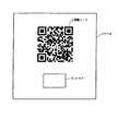
図2は物品に貼付されるラベル1を示すもので、このラベル1には、情報コードとして二次元コードの一種であるQRコード2が付されていると共に、IDタグ3が固着されている。このQRコード2を読み取るコード読取手段としての手持ち式の二次元コード読取装置4は図3に示されている。この二次元コード読取装置4は、リーダライタ手段を含んで構成されQRコード2の画像を取り込んで解読する機能と、IDタグ3と電波により通信してそのメモリに対して情報の読み書きを行う機能とを有している。
【0009】
QRコード2およびIDタグ3には、識別情報の他、このラベル1を付す物品について、在庫管理、販売管理などの種々の管理を行いための情報が書き込まれている。QRコード2は、一次元コードに比べて多くの情報を書き込み可能であるが、種々の管理を実施するには、書き込み量が不足するので、IDタグ3にも各種の情報が書き込まれる。
【0010】
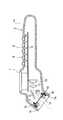
上記二次元コード読取装置4は、手持ち可能なケース5を主体とするもので、そのケース5には、握り部を構成する操作部6、液晶表示器7などが設けられている。操作部6には、多数のキースイッチ8が設けられ、これらキースイッチ8によって動作内容などを指示するようになっている。
【0011】
二次元コード読取装置4のケース5内には、プリント配線基板9が設けられており、このプリント配線基板9の一方の面に前記液晶表示器7およびキースイッチ8群が配設され、他方の面に光学的読取手段としてCCDエリアセンサ10および結像レンズ11が配設されている。
【0012】
ケース5の前端開口は読取口5aとされ、ここに別のプリント配線基板12が設けられている。このプリント配線基板12の前面側には、中央に形成された孔12aの周囲に位置して照明用光源としてのLED(発光ダイオード)13が搭載されていると共に、このLED13に対向する照明用レンズ14が配設されている。また、ケース5内において、読取口5aと結像レンズ11との間には、反射ミラー15が配設されている。
【0013】
QRコード2の読み取りは、読取口5aをラベル1にほぼ接触させた状態で行う。そして、LED13の発する光は照明用レンズ14により拡散されてラベル1を照明し、その反射光は読取口5aから入射され、途中で反射ミラー15により曲げられて結像レンズ11によってCCDエリアセンサ10に結像されるようになっている。
【0014】
一方、読取口5aのプリント配線基板12の表裏両側にはボビン16および17が設けられており、表側のボビン16に送信アンテナコイル18が巻装され、裏側のボビン17に受信アンテナコイル19が巻装されている。なお、送信アンテナコイル18および受信アンテナコイル19は、1個のアンテナコイルで共用する構成であっても良い。
【0015】
図4は二次元コード読取装置4の電気的構成を示しており、上述した液晶表示器7、キースイッチ8群、CCDエリアセンサ10、LED13、送信アンテナコイル18、受信アンテナコイル19の他に、制御回路20、増幅回路21、A/D変換回路22、同期パルス発生回路23、アドレス発生回路24、画像メモリ25、通信I/F回路26、復調部27、変調部28などを備えている。
【0016】
制御回路20は、CPU、ROM、RAM、I/Oなどを備えたマイクロコンピュータタシステムとして構成され、ROMに記憶されているプログラムに従って動作する。また、制御回路20には、液晶表示器7、キースイッチ8群、通信I/F回路26などが接続されており、入出力制御も行う。
【0017】
CCDエリアセンサ10は受光素子であるCCDを二次元的に配列して有し、LED13の反射光を結像してその二次元画像を水平方向の走査線信号として増幅回路21に与えられる。増幅回路21は、制御回路20からのゲインコントロール電圧に対応する増幅率でCCDエリアセンサ10から出力された走査線信号を増幅し、A/D変換回路22に出力する。そして、A/D変換回路22は、アナログの走査線信号をデジタル信号に変換する。このA/D変換回路22でデジタル信号に変換されたデータは多値データであり、この多値データは画像メモリ25に記憶される。そして、制御回路20が画像メモリ25に記憶された多値データに基づいて二次元コードを解読し、一時記憶手段としてのRAMに記憶させる。なお、この多値データは、各画素が8ビット(0〜255)の階調値を有するものとなっている。
【0018】
同期パルス発生回路23は、CCDエリアセンサ10から出力される二次元画像データのパルスより十分細かい同期パルスを出力する。アドレス発生回路24は、この同期パルス発生回路23から与えられる同期パルスをカウントして画像メモリ25に対するアドレスを発生させる。そして、デジタル信号に変換された多値の画像データはアドレス毎に8ビット単位で画像メモリ25に書き込まれる。なお、液晶表示器7は例えば2階調の液晶として構成されており、画像メモリ25に書き込まれた画像データを表示するためなどに用いられる。
【0019】
通信I/F回路26は、ホストコンピュータなどの外部装置との間で通信を行うものであり、例えば図示しない通信用発光素子を介して外部装置に送信したり、図示しない通信用受光素子を介して外部装置からの信号を受信する。
送信アンテナコイル18、受信アンテナコイル19、変調部27、復調部28は、IDタグ3と通信を行うためのもので、変調部27はIDタグ3との通信時に、まず基準信号を変調して電力用電波信号として送信アンテナコイル18から送信し、その後、送信すべきデータを電力用電波信号に重畳して送信アンテナコイル18から送信する。また、復調部27は、受信アンテナコイル19により受信した電波信号を復調し、データとして取り出す。
【0020】
一方、IDタグ3は、図5に示すように、電波信号を送受信するための通信手段としてのアンテナコイル29と、共振コンデンサ30と、制御用IC31と、平滑部32とを備えている。制御用IC31は、制御手段としてのCPU33の他、整流部34、変復調部35、識別情報および管理情報などの記憶手段としてのメモリ部36などを構成する半導体素子をワンチップ化したものである。この場合、メモリ部36は、動作プログラマブルなどを記憶したROM37と、一時記憶用として消去可能な不揮発性メモリ、例えばEEPROM38とを有している。そして、IDタグ3のEEPROM38には、IDタグ3が取り付けられる物品の情報が記憶されている。なお、共振コンデンサ30は、制御用IC31に設けても良いし、場合によってはなくとも良い。
【0021】
上記アンテナコイル29は、共振コンデンサ30と並列に接続されて共振回路を構成し、二次元コード読取装置4の送信アンテナ18から所定の高周波数の電力用電波信号が送信されてくると、これを受信して整流部34に供給する。整流部34は、平滑部32と共に動作用電源回路を構成するもので、共振回路から送信されてきた電力用電波信号を整流し、平滑部32により平滑化し且つ一定電圧の直流電力(動作用電力)にしてCPU33などに供給する。
【0022】
電力用電波信号に重畳して送信されるデータ信号は、変復調部35により復調されてCPU33に与えられる。CPU33は、メモリ部36のROM37に記憶された動作プログラムに従って動作するもので、変復調部35から入力される信号に応じた処理を実行し、受信したデータをメモリ部36のEEPROM38などに書き込んだり、EEPROM38からデータを読み出して変復調部35により変調し、アンテナコイル29から電波信号として送信したりする。
【0023】
EEPROM38の記憶領域は、識別情報書込領域と解読情報書込領域とに分けられており、識別情報書込領域には、ラベル1を貼付する物品について、その識別情報たる識別番号、QRコード2に書き込みできない情報などが書き込まれる。また、解読情報書込領域には、QRコード2の汚れや、破損などにより、不具合(誤り)と判断されたコードワードについて、その誤り訂正データを用いて解読されたデータが書き込まれるようになっている。
【0024】
ここで、QRコード2の構成、不具合の推定および不具合があった場合の誤り訂正の方式について説明する。
まず、QRコード2は図2に示すように二次元的な広がりを持ち、図7に示すように二次元コード読取装置1が取り込んだ画像中でQRコード2の存在位置を特定するために、特定寸法比率の正方形を組み合わせた位置決め用シンボル210a〜210cや、それら3個の位置決めシンボル210a〜210cの相互間に設けられ、白と黒とが交互に組み合わせられた各データセル位置の指標となる基準パターンであるタイミングセル220a、220bを備えている。
【0025】
QRコード2の内部は、n×nの正方形の升目(これが「セル」に相当する。)に区切られており、QRコード200の有する位置決め用シンボル210a〜210cは、例えば一辺の長さが7セルに相当する黒い正方形212、一辺の長さが5セルに相当する白い正方形214、一辺の長さが3セルに相当する黒い正方形216を同心状に重ね合わせた時にできる図形である。
【0026】
そのため、この位置決め用シンボル210a〜210cの中心付近を直線的に横切ると、黒、白、黒、白のパターンが1:1:3:1:1の比率で検出される。従って、この性質を利用して上述した比率で黒と白が交互に検出された場合、そのパターンを位置決め用シンボル210a〜210cの有力な候補と判断し、QRコード200の存在位置を確定するために優先的に検査する。そして、QRコード200の形状は、3個の位置決め用シンボル210a〜210cで一義的に決まる平行四辺形の範囲であると推定できる。
【0027】
なお、データは、位置決め用シンボル210a〜210cや、タイミングセル220a、220bなどを除外した情報記録領域230のセル(データセル)で表され、各データセルを白(明)或いは黒(暗)に色分けするころにより、各データセルを1ビットのデータに対応させている。図7では、分かり易くするために、データセルの白黒のパターンは省略してある。
【0028】
各データセルの位置は、3個の位置決めシンボル210a〜210cを、それぞれ縦方向と横方向の座標の指標として簡単な計算により求めることができる。このように位置が決定した各データセルの中心付近が黒であるか白であるかを判定して、黒を例えば「1」、白を「0」に対応させることにより、2値データとして認識でき、解読することができる。
【0029】
二次元コード読取装置1では、取り込んだQRコード2の画像に不具合がある場合には、QRコード2に含まれる誤り訂正データを用いて誤り訂正を行うことが行われる。ここで、画像の不具合とは、QRコード2自体の汚れや破損などによってQRコード2の画像の一部が正しく読み取れなくなっている状態をいう。
【0030】
一般に、二次元コードには高度な訂正能力を有する誤り訂正符号が用いられている。QRコード2では、図6に示すように、情報記録領域230がデータブロックと誤り訂正ブロックとに分割され、リード・ソロモン(以下、単に「RS」と言う。)符号化されている。ここで、誤り訂正ブロックはRS符号化のための冗長データである。なお、データブロックおよび誤り訂正ブロックは、コードワードと呼ばれる8ビットの情報が1単位になって構成されている。図6にD1〜D46およびE1〜E88で示すそれぞれがコードワードに対応する。以下、誤り訂正ブロックを「RSブロック」と称し、このRSブロックを構成するコードワードをRSコードワード(誤り訂正データ)、データブロックを構成するコードワードをデータコードワードと称することとする。
【0031】
ここで、図6に例示するQRコードでは、D1〜D23のデータコードワードとE1〜E44のRSデータコードとからなるブロック1、およびD24〜D46のデータコードワードとE45〜E88のRSデータコードとからなるブロック2という2つのブロックを有しており、このブロック1、2の単位でRS符号化がなされており、ブロック1、2の単位で誤り訂正が行われる。
【0032】
次に、一般的な誤り訂正について説明する。誤り訂正には、検出訂正と消失訂正の2種類の方式が存在する。
検出訂正は、大きく以下の3つのステップから構成される。
▲1▼符号からシンドローム多項式を求める。
▲2▼シンドローム多項式から誤り位置多項式および誤り数値多項式を求める。
▲3▼誤り位置多項式からチェンサーチ法により誤り位置を求め、その位置に対する誤りの大きさ(誤りパターン)を求めて誤り訂正を行う。
【0033】
QRコード2の例で言えば、符号化ブロックからシンドローム多項式を求め、シンドローム多項式から誤り位置多項式および誤り数値多項式を求める。そして、誤り位置多項式から誤り位置としてのコードワードを特定し、そのコードワードの誤りの大きさを求めて誤り訂正を行うというものである。
【0034】
一方、消失訂正方式は、誤りである符号の位置(消失位置)、すなわち誤りのあるコードワードが予め分かっていることを前提として、誤りの大きさのみを求めて誤り訂正を行うものである。
この消失訂正は、大きくは次の3つのステップから構成される。
▲1▼符号からシンドローム多項式を求める。
▲2▼消失位置から得られる消失多項式を用い、シンドローム多項式を修正し、消失数値多項式を求める。
▲3▼消失位置に対して誤りの大きさを求めて誤り訂正を行う。
【0035】
このように消失訂正では、誤り位置が分かっていることを前提として誤りの大きさのみを求めるため、検出訂正とは異なり、シンドローム多項式から求める多項式は消失数値多項式の1つだけとなる。従って、訂正能力は検出訂正の2倍になる。
【0036】
このように、誤り訂正については、上述したRS符号による方式が多く用いられているが、パリティ(誤り検出符号)を付加してこのパリティにより誤り位置の検出を行い、消失訂正を行って訂正効率を上げるようにしても良い。また、QRコード2では、白、黒のセルがランダムに分布する。この前提に立てば、白または黒の一方のセルだけで構成されるコードワードブロックは不具合として推定して検出訂正の処理をすることができる。
【0037】
次に、QRコード2の読取時の作用を図1に示すフローチャートをも参照しながら説明する。
二次元コード読取装置4の読取口5aをラベル1のQRコード2の記載部分にほぼ接触させた状態で、キースイッチ8群の中から所定のキースイッチを操作すると、LED13が点灯してQRコード2の記載部分を照明し、その反射光が結像レンズ11によりCCDエリアセンサ10に結像される。このCCDエリアセンサ10に結像された画像は多値のデジタルデータとして画像メモリ25に取り込まれる(ステップS1)。そして、制御回路20は、画像メモリ25に記憶された画像データに基づいて解読したQRコード2のデータコードワードを1ワードずつ当該制御回路20のRAMに記憶させるために、その記憶用に予め定められた領域の先頭アドレスカウンタ(アドレスCNT)を設定する(ステップS2)。
【0038】
制御回路20は画像メモリ25に記憶されたデジタルデータに基づいて、QRコード2のデータコードワードを所定の順序、この実施例ではD1から昇順で1ワードずつ解読し(ステップS3)、次いで、解読したデータコードワードに不具合があったか否かを判断する(ステップS4)。不具合がなければ、制御回路20はステップS4で「NO」と判断し、解読したデータコードワードを指定されたアドレスCNTに記憶させる(ステップS5)。次いで、制御回路20は、解読したデータコードワードが最後のものであるか否かを判断する(ステップS6)。最後でなかった場合、制御回路20はステップS6で「NO」と判断し、次に記憶させるべきデータコードワードのアドレスCNTをインクリメントし(ステップS7)、その後、前述のステップS3に戻って次のデータコードワードを解読する。
以上のようにしてデータコードワードを1つずつ解読してRAMに記憶させて行く動作を、最後のデータコードワードまで行うと、制御回路20はステップS6で「YES」と判断してQRコード2の解読を終了する。
【0039】
ところで、QRコード2に汚れが付くと、その汚れは最初は小さなものであっても、次第に広がって広い範囲に及んで行くようになる。QRコード2に破れや剥れが生じた場合も同様で、最初は小さな破れや剥れであっても、その破れや剥れは次第に進行して行く。汚れ、破れ、剥れなどの破損はデータコードワードに不具合を消磁させるが、その破損が小さいうちであれば、データコードワードに不具合があっても、RSコードワードによって解読可能である。
【0040】
さて、小さな汚れ、破れ、剥がれなどの破損によって、或るデータコードワードに不具合が生じたとすると、制御回路20はステップS4で「YES」と判断し、次のステップS8に移行する。このステップS8で、制御回路20は、送信アンテナコイル18から電力用電波信号を送信してIDタグ3と通信し、当該IDタグ3のEEPROM38の解読情報書込領域のデータを読み出す。
【0041】
その後、制御回路20は読み出したデータを、先頭アドレスのものから検索し、記憶されている不具合データコードワードの格納先アドレス(制御回路20のRAMに格納されるときのそのRAMのアドレス)が現在データコードワードを格納しようとしているアドレスCNTと一致しているか否かを判断する(ステップS9)。アドレスがアドレスCNTと一致していない場合には、制御回路20はステップS9で「NO」と判断し、解読情報書込領域における次のアドレスのデータを検索する(ステップS10)。そして、その検索したデータは最後のものか否かを判断し(ステップS11)、最後のものでなかった場合(ステップS11で「NO」)、ステップS9に戻って記憶されている不具合データコードワードの格納先アドレスがアドレスCNTと一致しているか否かを判断する。
【0042】
アドレスが不一致(ステップS9で「NO」)で、検索したデータが最後のものであった(ステップS11で「YES」)場合、制御回路20はステップS12に移行し、RSコードワードによる誤り訂正を行う動作を実行し、次に訂正が可能かどうかを判断する(ステップS13)。なお、破損が相当程度進行していて訂正データを取得することが困難な場合には、制御回路20はステップS13で「NO」と判断し、QRコード2の解読を終了する。
【0043】
訂正可能の場合、制御回路20はステップS13で「YES」と判断し、次のステップS14でIDタグ3と通信してEEPROM38の解読情報書込領域の空き部分の先頭アドレスを読み出す。そして、制御回路20は次のステップS15で、IDタグ3のEEPROM38の解読情報書込領域の空き部分の先頭アドレスに解読データとアドレスCNTを書き込むと共に、当該制御回路20のRAMのアドレスCNTに解読データを格納し、前述のステップS6に戻って上述のような動作を実行する。
【0044】
ところで、QRコード2が破損していて、以前のQRコード2の解読の際にも不具合があるとして、誤り訂正により解読したデータが既にIDタグ3に書き込まれている場合がある。この場合には、制御回路20は前記ステップS9の実行時に「YES」となり、ステップS16に進行する。そして、このステップS16でIDタグ3から読み出した解読データを当該制御回路20のRAMのアドレスCNTに書き込み、その後、前記ステップS6に戻って上述のような動作を続行する。
【0045】
このように本実施例によれば、QRコード2の破損程度が小さいうちは、不具合のあるデータコードワードはRSコードワードによって訂正が可能であるため、その訂正が可能なうちに、データコードワードの解読データをIDタグ3に記憶させておく。この解読ワードの記憶は、破損が進行して行くに伴って、順次不具合となって行くデータコードワードについて順に実行されるので、QRコード2の破損程度が大きくなっても、QRコード2の解読が不能となるおそれがない。
【0046】
図8は本発明の他の実施例を示す。この実施例は、取り込んだ情報コードに不具合があったとき、その発生率が所定値、QRコードの例ではコード面積の30%以内であった場合には、RSコードワードにて誤り訂正が可能であるので、発生率が誤り訂正可能な所定値以内であるときには、IDタグから解読データを取得するのではなく、RSコードワードによる誤り訂正によって解読データを取得するようにしたものである。
【0047】
この制御の内容を図8により具体的に説明するに、まず、情報コードとしてのQRコード2を解読するために、その画像を画像メモリ25に取り込む(ステップB1)。すると、制御回路20は、QRコードの画像データに基づいて解読処理を実行し(ステップB2)、全てのデータコードワードの解読に成功したか否かを判断する(ステップB3)。そして、全てのデータコードワードの解読に成功していれば、ステップB3で「YES」となり、QRコードの解読を終了(エンド)する。
【0048】
さて、解読不能なデータコードワードがあった場合、制御回路20は、ステップB3で「NO」と判断し、ステップB4に移行する。このステップB4で制御回路20は、解読不能なデータコードワードが訂正可能な範囲、例えば全体の30%以内であるか否かを判断する。解読不能なデータコードワードが全体の30%以内であった場合、制御回路20はステップB4で「YES」と判断してステップB5に移行し、RSコードワードによる誤り訂正を行う動作を実行する。次いで、制御回路20は、誤り訂正による解読が成功したか否かを判断する(ステップB6)。
【0049】
誤り訂正による解読に成功した場合(ステップB6で「YES」)、制御回路20は、IDタグ3と通信し、誤りで訂正により解読したデータをIDタグ3のEEPROM38に書き込み(ステップB7)、エンドとなる。このEEPROM38への解読データの書き込みは、上述の一実施例にて説明したと同様に、その解読データが制御回路20のRAMに書き込まれるアドレスCNTと共に書き込まれるものである。
【0050】
誤り訂正による解読が不成功であった場合(ステップB6で「NO」)、制御回路20は、IDタグ3と通信し、解読し得なかったデータコードワードの解読データがEEPROM38の解読情報書込領域に記憶されているか否かを検索する(ステップB8)。この場合の検索も、上述の一実施例と同様に、データコードワードが制御回路20のRAMに書き込まれるべきアドレスCNTと同一のアドレスCNTを有する解読データがあるか否かによって行う。そして、解読し得なかったデータコードワードの解読データがEEPROM38に記憶されている場合(ステップB8で「YES」)、制御回路20は、EEPROM38からその解読データを読み出して当該制御回路20のRAMのアドレスCNTに書き込み(ステップB9)、エンドとなる。なお、解読し得なかったデータコードワードの解読データがEEPROM38に記憶されていなかった場合(ステップB8で「NO」)、制御回路20は、ステップB12に移行し、ここで液晶表示器7に「解読不能」の文字表示を行うなどのエラー処理を実行し、エンドとなる。
【0051】
一方、QRコードの画像データに基づいて解読処理を実行した結果、解読不能なデータコードワードが全体の30%を越えていた場合(ステップB4で「NO」)、制御回路20は、次にIDタグ3と通信し、EEPROM38の解読情報書込領域に、解読し得なかったデータコードワードの中の一つが記憶されているか否かを判断(検索)する(ステップB10)。EEPROM38に解読データが記憶されていた場合(ステップB10で「YES」)、制御回路20は、その解読データをEEPROM38から読み出して当該制御回路20のRAMのアドレスCNTに書き込む(ステップB11)。この解読データの書き込みにより、解読不能となっているデータコードワードの全体に対する割合が減少する。
【0052】
その後、制御回路20は、再びステップB4に戻り、解読不能なデータコードワードが全体の30%以内であるか否かを判断する。そして、制御回路20は、解読不能なデータコードワードが全体の30%以内となっていれば(ステップB4で「YES」)、ステップB5に移行し、前述したと同様の処理を実行してエンドとなる。
【0053】
また、依然として解読不能なデータコードワードが全体の30%を越えている場合には(ステップB4で「NO」)、制御回路20は、30%以内になるまでIDタグ3のEEPROM38に記憶されている解読データを一つずつ読み出してRAMに記憶する動作を繰り返す(ステップB10、B11、B4で「NO」の繰り返し)。これにより、解読不能なデータコードワードが全体の30%以内となると(ステップB4で「YES」)、制御回路20は、前述のステップB5以降の動作を実行してエンドとなる。なお、ステップB10、B11、B4で 「NO」を繰り返し実行している間に、解読不能となっているデータコードワードの解読データがEEPROM38に存在していなくなった場合には、制御回路20は、ステップB10で「NO」となってステップB12に移行し、エラー処理を実行してエンドとなる。
【0054】
このように本実施例によれば、解読不能なデータコードワードの発生率が所定値(30%)以内である場合には、IDタグ3から解読データを読み出すことなく、RSコードワードによる誤り訂正を実行して解読し、その解読データをIDタグ3のEEPROM38に書き込むので、QRコードの破損が少ないうちに解読データをEEPROM38に記憶させて置くことができる。
【0055】
そして、QRコードの破損が進んだ場合でも、解読不能なデータコードワードの全てをIDタグ3のEEPROM38から読み出してRAMに記憶させるのではなく、EEPROM38からの解読データの読み出しによって未解読部分が少なくなり、全体に占める割合が所定値以内になると、以後はRSコードワードによる誤り訂正を実行して解読するので、シリアル通信によってデータの授受を行わざるを得ず、データ取得に時間のかかるIDタグ3とのデータ交換を極力減少させてQRコードの解読全体の所要時間を短縮することができる。
【0056】
なお、本発明は上記し且つ図面に示す実施例に限定されるものではなく、以下のような拡張或いは変更が可能である。
情報コードはQRコード2に限られない。また、二次元コードに限らず、バーコードなどの一次元コードであっても良い。
不具合部分の検出方式或いは推定方式も上記実施例によるものに限られない。
誤り訂正データはRS符号によるものに限られない。
不具合のあるデータコードワードの解読データがIDタグ3に書き込まれているか否かを判断する手段は、データコードワードの番号を解読データと共にEEPROM38に書き込んでおいて、データコードワードに不具合があった場合にその番号がIDタグ3のEEPROM38の解読情報書込領域に格納されているか否かによるものであっても良い。
【図面の簡単な説明】
【図1】本発明の一実施例におけるQRコードの読取動作の内容を示すフローチャート
【図2】ラベルの平面図
【図3】二次元コード読取装置の断面図
【図4】二次元コード読取装置の電気的構成を示すブロック図
【図5】IDタグの電気的構成を示すブロック図
【図6】QRコードのコード情報を構成するコードワードと符号化されたブロックとの関係を示す図
【図7】QRコードの構成を示す図
【図8】本発明の他の実施例を示すフローチャート
【符号の説明】
図中、1はラベル、2はQRコード、3はIDタグ、4は二次元コード読取装置(情報コード読取手段、リーダライタ手段)、10はCCDエリアセンサ、20は制御回路、38はEEPROM(メモリ)である。[0001]
In the present invention, information on the destruction portion of the information code is stored in the ID tag to prevent unreadableness due to the progress of destruction.Affection The present invention relates to a method for decoding an information code and a decoding system.
[0002]
[Problems to be solved by the invention]
In order to carry out distribution, sales, inventory management, etc., a label printed with a one-dimensional code such as a barcode or a two-dimensional code such as a QR code is attached to an article. Among them, the two-dimensional code is configured to include error correction data, and even if part of the data is destroyed due to dirt or damage, the error correction data can be used to decipher the destroyed part. ing.
[0003]
However, it is good as long as the code breakage is small, but when the breakage gradually progresses and exceeds a certain range, it is no longer easy to decode with the error correction data, and reading (decoding) of the two-dimensional code becomes impossible. In this case, the article cannot be managed by the two-dimensional code, and a problem arises that the label must be changed.
[0004]
The present invention has been made in view of the above circumstances, and its purpose is to be able to decipher the code even if the destruction of the code progresses and the destruction range becomes wideEmotion The present invention provides a method and system for decoding an information code.
In the present invention, the information code label includes not only a small piece (so-called label) provided with an information code and an ID tag, but also an information code printed on an article or its packaging device and attached with an ID tag. Including.
[0005]
[Means for Solving the Problems]
In the present invention, an ID code is attached to an information code label, and when the information code reading means takes the information code as an image and reads information based on the image of the information code, the information code The reading means corrects an error caused by a defect in the image using the error correction data to acquire the decoded data, and writes the decoded data into the decoded information writing area of the ID tag memory via the reader / writer means. For this reason, even if the destruction of the information code progresses gradually and the reading by the information code reading means becomes impossible, it is possible to read the information code by using the decoded data written in the memory of the ID tag. It becomes.
The information code reading means described above can be configured to include reader / writer means. By doing so, both means can be configured compactly.
[0006]
In addition, the present invention obtains decryption data using error correction data when the defect occurrence rate is within a predetermined value when there is a defect in the image in which the information code is captured, and the defect occurrence rate is a predetermined value. If it exceeds the limit, search whether the decryption data of the defective part is written in the memory of the ID tag, and if it is written, the decryption data of the defective part is sequentially obtained via the reader / writer means, As a result, when the defect occurrence rate falls within a predetermined value, acquisition of decoded data using error correction data may be executed.
[0007]
In this way, even if not all of the defective part is acquired from the ID tag, even if not all of the decrypted data of the defective part is acquired from the ID tag, if the part is replaced with the decrypted data, an error will occur afterwards. Since the decoded data is acquired using the correction data, the number of times of communication with the ID tag which takes time can be reduced as much as possible, and the time required for decoding the information code can be reduced.
[0008]
DETAILED DESCRIPTION OF THE INVENTION
In the following, an embodiment of the present invention will be described with reference to FIGS. 1 to 7 with a QR code, which is a kind of two-dimensional code, being read.
FIG. 2 shows a
[0009]
In the QR code 2 and the ID tag 3, in addition to the identification information, information for performing various management such as inventory management and sales management is written for the article to which the
[0010]
The two-dimensional code reading device 4 is mainly composed of a case 5 that can be held by hand, and the case 5 is provided with an
[0011]
A printed wiring board 9 is provided in the case 5 of the two-dimensional code reader 4, and the liquid crystal display 7 and the key switch 8 group are disposed on one surface of the printed wiring board 9, and the other side. A
[0012]
The front end opening of the case 5 is a
[0013]
The QR code 2 is read in a state where the
[0014]
On the other hand,
[0015]
FIG. 4 shows the electrical configuration of the two-dimensional code reader 4. In addition to the liquid crystal display 7, key switch 8 group,
[0016]
The
[0017]
The
[0018]
The synchronization
[0019]
The communication I / F circuit 26 communicates with an external device such as a host computer. For example, the communication I / F circuit 26 transmits to an external device via a communication light emitting element (not shown), or passes through a communication light receiving element (not shown). To receive a signal from an external device.
The transmitting
[0020]
On the other hand, as shown in FIG. 5, the ID tag 3 includes an
[0021]
The
[0022]
The data signal transmitted by being superimposed on the power radio signal is demodulated by the
[0023]
The storage area of the
[0024]
Here, the configuration of the QR code 2, the estimation of the defect, and the error correction method when there is a defect will be described.
First, the QR code 2 has a two-dimensional spread as shown in FIG. 2, and in order to specify the presence position of the QR code 2 in the image captured by the two-
[0025]
The inside of the QR code 2 is divided into n × n square cells (this corresponds to “cells”), and the
[0026]
Therefore, when linearly crossing the vicinity of the center of the
[0027]
The data is represented by cells (data cells) in the
[0028]
The position of each data cell can be obtained by simple calculation using the three
[0029]
In the two-
[0030]
In general, an error correction code having a high correction capability is used for a two-dimensional code. In the QR code 2, as shown in FIG. 6, the
[0031]
Here, in the QR code illustrated in FIG. 6, the
[0032]
Next, general error correction will be described. There are two types of error correction, detection correction and erasure correction.
The detection correction is mainly composed of the following three steps.
(1) Find the syndrome polynomial from the sign.
(2) An error position polynomial and an error numerical polynomial are obtained from the syndrome polynomial.
(3) The error position is obtained from the error position polynomial by the Chien search method, and the error size (error pattern) for the position is obtained to correct the error.
[0033]
In the example of QR code 2, a syndrome polynomial is obtained from the encoded block, and an error position polynomial and an error numerical value polynomial are obtained from the syndrome polynomial. Then, the code word as the error position is specified from the error position polynomial, and the error correction of the code word is obtained to perform error correction.
[0034]
On the other hand, the erasure correction method performs error correction by obtaining only the magnitude of the error on the assumption that the position of the code that is an error (erasure position), that is, the codeword having the error is known in advance.
This erasure correction is roughly composed of the following three steps.
(1) Find the syndrome polynomial from the sign.
(2) The erasure polynomial obtained from the erasure position is used to correct the syndrome polynomial to obtain the erasure numerical polynomial.
(3) Error correction is performed by determining the size of the error for the erasure position.
[0035]
In this way, in erasure correction, since only the magnitude of error is obtained on the assumption that the error position is known, unlike the detection correction, only one erasure value polynomial is obtained from the syndrome polynomial. Accordingly, the correction capability is twice that of detection correction.
[0036]
As described above, for error correction, the above-described RS code method is often used. However, a parity (error detection code) is added, an error position is detected using this parity, erasure correction is performed, and correction efficiency is improved. You may make it raise. In QR code 2, white and black cells are randomly distributed. Based on this assumption, a codeword block composed of only one of white and black cells can be estimated as a defect and subjected to detection and correction processing.
[0037]
Next, the operation when the QR code 2 is read will be described with reference to the flowchart shown in FIG.
When a predetermined key switch is operated from the group of key switches 8 with the reading
[0038]
Based on the digital data stored in the
When the operation of decoding the data code words one by one and storing them in the RAM as described above is performed up to the last data code word, the
[0039]
By the way, when the QR code 2 is soiled, even if the soiling is small at first, it gradually spreads to reach a wide range. The same applies to the case where the QR code 2 is torn or peeled off. Even if the QR code 2 is a little torn or peeled at first, the tearing or peeling is gradually progressing. Damage such as dirt, tearing, or peeling causes the data code word to be demagnetized. However, as long as the damage is small, even if the data code word is defective, it can be decoded by the RS code word.
[0040]
Now, assuming that a certain data code word is defective due to damage such as small dirt, tearing, or peeling, the
[0041]
Thereafter, the
[0042]
If the addresses do not match (“NO” in step S9) and the retrieved data is the last one (“YES” in step S11), the
[0043]
If correction is possible, the
[0044]
By the way, there is a case where the data decoded by the error correction has already been written in the ID tag 3 because the QR code 2 is damaged and there is a problem when the previous QR code 2 is decoded. In this case, the
[0045]
As described above, according to the present embodiment, while the QR code 2 is less damaged, the defective data code word can be corrected by the RS code word. Is stored in the ID tag 3. The storage of the decryption word is executed sequentially for the data codewords that sequentially become defective as the damage progresses. Therefore, even if the degree of damage of the QR code 2 increases, the decryption of the QR code 2 is performed. There is no risk of being disabled.
[0046]
FIG. 8 shows another embodiment of the present invention. In this embodiment, when there is a defect in the imported information code, the error rate can be corrected with the RS code word if the occurrence rate is a predetermined value, and in the example of QR code, it is within 30% of the code area. Therefore, when the occurrence rate is within a predetermined value capable of error correction, the decoded data is not acquired from the ID tag, but is acquired by error correction using the RS code word.
[0047]
The contents of this control will be described in detail with reference to FIG. 8. First, in order to decode the QR code 2 as the information code, the image is taken into the image memory 25 (step B1). Then, the
[0048]
When there is a data code word that cannot be decoded, the
[0049]
When decoding by error correction is successful (“YES” in step B6), the
[0050]
If decoding by error correction is unsuccessful (“NO” in step B 6), the
[0051]
On the other hand, as a result of executing the decoding process based on the image data of the QR code, when the undecodable data code word exceeds 30% (“NO” in step B4), the
[0052]
Thereafter, the
[0053]
In addition, when the data code word still undecipherable exceeds 30% (“NO” in step B4), the
[0054]
As described above, according to this embodiment, when the occurrence rate of unreadable data code words is within a predetermined value (30%), error correction using RS code words is performed without reading decoded data from the ID tag 3. , And the decrypted data is written into the
[0055]
Even when the QR code is further damaged, not all the unreadable data code words are read from the
[0056]
The present invention is not limited to the embodiments described above and shown in the drawings, and can be expanded or changed as follows.
The information code is not limited to QR code 2. Moreover, not only a two-dimensional code but a one-dimensional code such as a barcode may be used.
The detection method or estimation method of the defective part is not limited to that according to the above embodiment.
The error correction data is not limited to the RS code.
The means for determining whether or not the decrypted data of the defective data code word is written in the ID tag 3 is that the data code word has a problem when the data code word number is written in the
[Brief description of the drawings]
FIG. 1 is a flowchart showing details of a QR code reading operation according to an embodiment of the present invention.
[Fig. 2] Plan view of the label
FIG. 3 is a sectional view of a two-dimensional code reader.
FIG. 4 is a block diagram showing an electrical configuration of the two-dimensional code reader.
FIG. 5 is a block diagram showing an electrical configuration of an ID tag
FIG. 6 is a diagram showing a relationship between codewords constituting code information of QR codes and encoded blocks;
FIG. 7 is a diagram showing the structure of a QR code
FIG. 8 is a flowchart showing another embodiment of the present invention.
[Explanation of symbols]
In the figure, 1 is a label, 2 is a QR code, 3 is an ID tag, 4 is a two-dimensional code reader (information code reading means, reader / writer means), 10 is a CCD area sensor, 20 is a control circuit, and 38 is an EEPROM ( Memory).
Claims (4)
Translated fromJapanese前記IDタグのメモリに対し読み書き可能なリーダライタ手段と、
前記情報コードを読み取る情報コード読取手段とを備え、
前記IDタグのメモリは、識別情報などを書き込む識別情報書込領域の他に、解読情報書込領域を有し、
前記情報コード読取手段が前記情報コードを画像として取り込んで当該情報コードに基づいて情報を読み取る際にその画像に不具合があるとき、前記IDタグのメモリに書き込まれている不具合部分の解読データについては、当該メモリの解読データを前記リーダライタ手段を介して読み取ることによって取得し、
前記IDタグのメモリに書き込まれていない不具合部分の解読データについては、前記情報コード読取手段が前記誤り訂正データを用いて前記不具合によって生ずる誤りを訂正することにより取得すると共に、その取得した解読データを、前記リーダライタ手段を介して前記IDタグのメモリの前記解読情報書込領域に書き込むことを特徴とする情報コードの解読方法。An information code label with an ID tag having information code including the error correctiondata, and a read-write memory,
Reader / writer means readable and writable with respect to the memory of the ID tag;
An information code reading means for reading the information code,
Memory of the ID tag, in addition to the identification information write area for writing the identification information or the like,have a decode information writearea,
When the information code reading means captures the information code as an image and reads information based on the information code, when the imageis defective, the decoded data of the defective portion written in the memory of the ID tag , By reading the decrypted data of the memory through the reader / writer means,
The decrypted data of the defective portion that is not written in the memory of the ID tag is acquired by the information code reading means correcting the error caused by the defective using the error correction data, and the acquired decoded data Is written into thedecoding information writing area of the memory of the ID tag via the reader / writer means .
前記IDタグのメモリに対し読み書き可能なリーダライタ手段と、
前記情報コードを読み取る情報コード読取手段とを備え、
前記IDタグのメモリは、識別情報などを書き込む識別情報書込領域の他に、解読情報書込領域を有し、
前記情報コード読取手段は、前記情報コードを画像として取り込んで当該情報コードに基づいて情報を読み取る際にその画像に不具合があるとき、前記IDタグのメモリに書き込まれている不具合部分の解読データについては、当該メモリの解読データを前記リーダライタ手段を介して読み取ることによって取得し、前記IDタグのメモリに書き込まれていない不具合部分の解読データについては、前記誤り訂正データを用いて前記不具合によって生ずる誤りを訂正することにより取得すると共に、その取得した解読データを、前記リーダライタ手段を介して前記IDタグのメモリの前記解読情報書込領域に書き込むことを特徴とする情報コードの解読システム。An information code label including an information code including error correction data andan ID taghaving a readable / writable memory;
Reader / writer means readable and writable with respect to the memory of the ID tag;
An information code reading means for reading the information code,
The memory of the ID tag has a decoding information writing area in addition to an identification information writing area for writing identification information and thelike ,
Said information code readingmeans, when there is a defect in the image when reading information on the basis of the information code fetches the information code as an image, the decrypted data defect portion written in the memory of the ID tag Is obtained by reading the decoded data of the memory through the reader / writer means, and the decoded data of the defective portion not written in the memory of the ID tag is caused by the defect using the error correction data. An information code decodingsystem , which is obtained by correcting an error, and writing the acquired decoded data into the decoding information writing area of the memory of the ID tag via the reader / writer means.
前記IDタグのメモリに対し読み書き可能なリーダライタ手段と、
前記情報コードを読み取る情報コード読取手段とを備え、
前記情報コード読取手段が前記情報コードを画像として取り込んで当該情報コードに基づいて情報を読み取る際にその画像に不具合があり、且つ当該不具合の発生率が所定値以内である場合に、前記誤り訂正データを用いて前記不具合によって生ずる誤りを訂正することにより当該不具合部の解読データを取得して、その取得した解読データを、前記リーダライタ手段を介して前記IDタグのメモリに書き込み、前記不具合の発生率が所定値を越える場合には、前記不具合部分の解読データが前記IDタグのメモリに書き込まれているかどうかを検索し、書き込まれている場合には、前記不具合部分の解読データを前記リーダライタ手段を介して逐次取得し、その結果、不具合の発生率が所定値以内になった場合には、前記誤り訂正データを用いた前記解読データの取得を実行することを特徴とする情報コードの解読方法。An information code including error correction data, and an information code label including an ID tag including a readable / writable memory;
Reader / writer means readable and writable with respect to the memory of the ID tag;
An information code reading means for reading the information code,
When the information code reading means captures the information code as an image and reads information based on the information code, if the image has a defect and the occurrence rate of the defect is within a predetermined value, the error correction Using the data to correct the error caused by the defect, obtain the decrypted data of the defective part, write the acquired decrypted data to the memory of the ID tag via the reader / writer means, When the occurrence rate exceeds a predetermined value, it is searched whether or not the decrypted data of the defective part is written in the memory of the ID tag. If it is written, the decrypted data of the defective part is stored in the reader. If the failure rate is within a predetermined value as a result of sequentially obtaining through the writer means, the error correction data is Decryption method information code andexecutes the acquired decryption data had.
Priority Applications (2)
| Application Number | Priority Date | Filing Date | Title |
|---|---|---|---|
| JP2001359466AJP3896827B2 (en) | 2001-02-21 | 2001-11-26 | Information code decoding method and decoding system |
| US10/078,274US6722565B2 (en) | 2001-02-21 | 2002-02-20 | Data code label, a method of decoding data codes, and an optical data code decoding system |
Applications Claiming Priority (3)
| Application Number | Priority Date | Filing Date | Title |
|---|---|---|---|
| JP2001-45032 | 2001-02-21 | ||
| JP2001045032 | 2001-02-21 | ||
| JP2001359466AJP3896827B2 (en) | 2001-02-21 | 2001-11-26 | Information code decoding method and decoding system |
Publications (2)
| Publication Number | Publication Date |
|---|---|
| JP2002324222A JP2002324222A (en) | 2002-11-08 |
| JP3896827B2true JP3896827B2 (en) | 2007-03-22 |
Family
ID=26609814
Family Applications (1)
| Application Number | Title | Priority Date | Filing Date |
|---|---|---|---|
| JP2001359466AExpired - Fee RelatedJP3896827B2 (en) | 2001-02-21 | 2001-11-26 | Information code decoding method and decoding system |
Country Status (2)
| Country | Link |
|---|---|
| US (1) | US6722565B2 (en) |
| JP (1) | JP3896827B2 (en) |
Families Citing this family (39)
| Publication number | Priority date | Publication date | Assignee | Title |
|---|---|---|---|---|
| US7577618B2 (en)* | 2000-10-10 | 2009-08-18 | Stamps.Com Inc. | Generic value bearing item labels |
| JP3876783B2 (en)* | 2002-07-19 | 2007-02-07 | 株式会社デンソーウェーブ | Information code reading method |
| WO2004097860A1 (en)* | 2003-03-20 | 2004-11-11 | Microbridge Technologies Inc. | Trimminig temperature coefficients of electronic components and circuits |
| US7192791B2 (en)* | 2003-06-19 | 2007-03-20 | Brooks Automation, Inc. | Semiconductor wafer having an edge based identification feature |
| JP4770871B2 (en)* | 2003-08-28 | 2011-09-14 | 株式会社デンソーウェーブ | Contactless data carrier, its terminal equipment and access system |
| US20050083413A1 (en)* | 2003-10-20 | 2005-04-21 | Logicalis | Method, system, apparatus, and machine-readable medium for use in connection with a server that uses images or audio for initiating remote function calls |
| US7818269B2 (en)* | 2003-12-08 | 2010-10-19 | Stamps.Com Inc. | Computer postage and mailing tracking labels |
| US7778939B2 (en)* | 2003-12-29 | 2010-08-17 | Stamps.Com Inc. | Outbound mail piece tracking |
| JP4460903B2 (en)* | 2004-01-20 | 2010-05-12 | 株式会社東芝 | ID mark recognition method for semiconductor wafer |
| US7762460B2 (en)* | 2004-02-18 | 2010-07-27 | Nec Corporation | Information processing device for using bar code and radio frequency-identification tag |
| US7055750B2 (en)* | 2004-05-07 | 2006-06-06 | Battelle Memorial Institute K1-53 | Device and method for encoding data in multiple media |
| KR100679630B1 (en)* | 2004-07-27 | 2007-02-07 | 주식회사 칼라짚미디어 | Hybrid tag interface system and interfacing method |
| US8005762B2 (en)* | 2004-08-20 | 2011-08-23 | Stamps.Com Inc. | Automated handling of computer-based postage system printing errors |
| JP2006082490A (en)* | 2004-09-17 | 2006-03-30 | Canon Inc | Recording medium and printing apparatus |
| US8553968B1 (en)* | 2005-02-18 | 2013-10-08 | Western Digital Technologies, Inc. | Using optical character recognition augmented by an error correction code to detect serial numbers written on a wafer |
| JP4389812B2 (en)* | 2005-03-03 | 2009-12-24 | 株式会社デンソーウェーブ | Optical information reader |
| KR100828539B1 (en)* | 2005-09-20 | 2008-05-13 | 후지제롯쿠스 가부시끼가이샤 | A storage medium storing a two-dimensional code detection method, a detection device, and a detection program |
| WO2008072219A2 (en)* | 2006-12-14 | 2008-06-19 | Symlink Technologies | An apparatus system and method for encoding and decoding optical symbols |
| US7874496B2 (en)* | 2008-01-04 | 2011-01-25 | Microsoft Corporation | Optically readable tag |
| FI124035B (en)* | 2008-07-30 | 2014-02-14 | Upc Konsultointi Oy | Collection of codes on mobile device |
| US20100327066A1 (en)* | 2009-06-25 | 2010-12-30 | Samsung Electronics Co. Ltd. | Network based reliable decoding of bar codes |
| US9082234B1 (en) | 2009-07-10 | 2015-07-14 | Stamps.Com Inc. | Automatic guarantee delivery tracking and reporting for united states postal service postage refunds for paid computer-based postage |
| JP5359858B2 (en)* | 2009-12-25 | 2013-12-04 | 株式会社デンソーウェーブ | Information code and information code generation method |
| US8456679B2 (en) | 2010-08-03 | 2013-06-04 | Xerox Corporation | System and method for generating a remote job submission accelerator report in a multi-function device |
| US9049315B2 (en) | 2010-09-14 | 2015-06-02 | Xerox Corporation | Method, system and computer-usable medium for ranking networked rendering devices with visual cues |
| US8807421B2 (en)* | 2011-04-26 | 2014-08-19 | Michael Alexander Johnson | Composite code with dynamic linking to internet addresses |
| CN102568608B (en)* | 2012-02-24 | 2014-08-27 | 南京大学 | Improved method for strengthening QR (Quick Response) code error correcting capability |
| US20150169928A1 (en) | 2012-03-01 | 2015-06-18 | Sys-Tech Solutions, Inc. | Methods and a system for verifying the identity of a printed item |
| US20150379321A1 (en) | 2012-03-01 | 2015-12-31 | Sys-Tech Solutions, Inc. | Methods and a system for verifying the authenticity of a mark |
| RS57033B1 (en) | 2012-03-01 | 2018-05-31 | Sys Tech Solutions Inc | Unique identification information from marked features |
| MX368515B (en)* | 2014-09-23 | 2019-10-07 | Sys Tech Solutions Inc | Methods and a system for verifying the authenticity of a mark. |
| US9904886B2 (en)* | 2015-02-06 | 2018-02-27 | Lawrence F Glaser | Method of identifying, locating, tracking, acquiring and selling tangible and intangible objects utilizing predictive transpose morphology |
| US9940572B2 (en) | 2015-02-17 | 2018-04-10 | Sys-Tech Solutions, Inc. | Methods and a computing device for determining whether a mark is genuine |
| EP3937080A1 (en) | 2015-06-16 | 2022-01-12 | SYS-Tech Solutions, Inc. | Methods and a computer device for determining whether a mark is geniune |
| BR112018068471A2 (en) | 2016-03-14 | 2019-01-22 | Sys Tech Solutions Inc | method to determine if a candidate brand is genuine, and computing device. |
| US11308480B2 (en)* | 2017-12-22 | 2022-04-19 | Paypal, Inc. | Anonymizing user identity via machine-readable codes |
| DE102018108741A1 (en)* | 2018-04-12 | 2019-10-17 | Klöckner Pentaplast Gmbh | Method for optical product authentication |
| CN111191154B (en)* | 2019-11-07 | 2022-11-25 | 国家电网有限公司 | A two-dimensional code management method for optical cable signs |
| US11216631B2 (en)* | 2020-04-24 | 2022-01-04 | Avocado Scan, Inc. | Contrast edge barcodes |
Family Cites Families (13)
| Publication number | Priority date | Publication date | Assignee | Title |
|---|---|---|---|---|
| JPH0720641U (en)* | 1993-09-24 | 1995-04-11 | 株式会社トキメック | Electronic data reading / writing device with optical data reading function and electronic data carrier with data for optical reading |
| JP2921395B2 (en)* | 1994-05-25 | 1999-07-19 | 松下電器産業株式会社 | Method of manufacturing electronic device having identification number |
| US6371375B1 (en)* | 1995-09-25 | 2002-04-16 | Intermec Ip Corp. | Method and apparatus for associating data with a wireless memory device |
| US6056199A (en)* | 1995-09-25 | 2000-05-02 | Intermec Ip Corporation | Method and apparatus for storing and reading data |
| JPH1040329A (en)* | 1996-07-19 | 1998-02-13 | Tesco:Kk | Bar code reading/rf tag reading and writing device |
| JPH10111904A (en)* | 1996-10-04 | 1998-04-28 | Matsushita Electric Ind Co Ltd | Barcode reading device and recording medium |
| US5949059A (en)* | 1996-12-09 | 1999-09-07 | International Business Machines Corporation | Tamper evident labelling system with embedded storage device |
| US5962834A (en)* | 1997-03-17 | 1999-10-05 | Markman; Herbert L. | Inventory tracking and management apparatus with multi-function encoding unit |
| US6126074A (en)* | 1998-01-28 | 2000-10-03 | Symbol Technologies, Inc. | Error correction in macro bar code symbols |
| EP1770592B1 (en)* | 1998-08-14 | 2009-10-07 | 3M Innovative Properties Company | Method of interrogating a package bearing an RFID tag |
| JP2000112354A (en)* | 1998-09-30 | 2000-04-21 | Toppan Forms Co Ltd | Delivery label with IC |
| US6109526A (en)* | 1998-11-17 | 2000-08-29 | Intermec Ip Corp. | Optical and passive electromagnetic reader for reading machine-readable symbols, such as bar codes, and reading wireless tags, such as radio frequency tags, and corresponding method |
| US20020180588A1 (en)* | 2001-06-05 | 2002-12-05 | Erickson David P. | Radio frequency identification in document management |
- 2001
- 2001-11-26JPJP2001359466Apatent/JP3896827B2/ennot_activeExpired - Fee Related
- 2002
- 2002-02-20USUS10/078,274patent/US6722565B2/ennot_activeExpired - Fee Related
Also Published As
| Publication number | Publication date |
|---|---|
| US6722565B2 (en) | 2004-04-20 |
| US20020113127A1 (en) | 2002-08-22 |
| JP2002324222A (en) | 2002-11-08 |
Similar Documents
| Publication | Publication Date | Title |
|---|---|---|
| JP3896827B2 (en) | Information code decoding method and decoding system | |
| US6371375B1 (en) | Method and apparatus for associating data with a wireless memory device | |
| US5723853A (en) | Bar code reader | |
| US6685095B2 (en) | Apparatus and method for decoding damaged optical codes | |
| US9918453B2 (en) | Tracking system | |
| EP1708118A2 (en) | Combination RFID/image reader | |
| CA2285626A1 (en) | Distortion resistant double-data correcting color transition barcode and method of generating and using same | |
| JPH03204790A (en) | Decoding of bar code from partial scanning | |
| US7789307B2 (en) | Identifier for memory tags | |
| WO2007001666A1 (en) | System and method for machine readable symbol backup for radio frequency identification tags | |
| JP5229652B2 (en) | Two-dimensional code, two-dimensional code generation method, computer-readable program for displaying two-dimensional code, authentication method using two-dimensional code, and information providing method using two-dimensional code | |
| JP4200951B2 (en) | Contactless data carrier, its terminal equipment and access system | |
| JP4394133B2 (en) | Information code, information code reader | |
| JP6171855B2 (en) | Information code and information code reader | |
| JP4770871B2 (en) | Contactless data carrier, its terminal equipment and access system | |
| JP5109902B2 (en) | RFID tag reader / writer device | |
| JP4591216B2 (en) | Information code reading system, information code reading device, and label | |
| JPH09274637A (en) | Two-dimensional code reader | |
| JP5169977B2 (en) | Information portable terminal | |
| JP4652201B2 (en) | Bar code symbol information reading method and bar code symbol information reading device | |
| JP2002216088A (en) | Information code | |
| JP2002007979A (en) | Information input device and information input system | |
| JP2002216073A (en) | Device for reading readable character or the like and method for the same | |
| JP2023172028A (en) | wireless tag system | |
| JP2010015353A (en) | Information code reading device management system |
Legal Events
| Date | Code | Title | Description |
|---|---|---|---|
| A621 | Written request for application examination | Free format text:JAPANESE INTERMEDIATE CODE: A621 Effective date:20031215 | |
| A977 | Report on retrieval | Free format text:JAPANESE INTERMEDIATE CODE: A971007 Effective date:20051222 | |
| A131 | Notification of reasons for refusal | Free format text:JAPANESE INTERMEDIATE CODE: A131 Effective date:20060110 | |
| A521 | Written amendment | Free format text:JAPANESE INTERMEDIATE CODE: A523 Effective date:20060306 | |
| TRDD | Decision of grant or rejection written | ||
| A01 | Written decision to grant a patent or to grant a registration (utility model) | Free format text:JAPANESE INTERMEDIATE CODE: A01 Effective date:20061128 | |
| A61 | First payment of annual fees (during grant procedure) | Free format text:JAPANESE INTERMEDIATE CODE: A61 Effective date:20061211 | |
| R150 | Certificate of patent or registration of utility model | Ref document number:3896827 Country of ref document:JP Free format text:JAPANESE INTERMEDIATE CODE: R150 Free format text:JAPANESE INTERMEDIATE CODE: R150 | |
| FPAY | Renewal fee payment (event date is renewal date of database) | Free format text:PAYMENT UNTIL: 20100105 Year of fee payment:3 | |
| FPAY | Renewal fee payment (event date is renewal date of database) | Free format text:PAYMENT UNTIL: 20110105 Year of fee payment:4 | |
| R250 | Receipt of annual fees | Free format text:JAPANESE INTERMEDIATE CODE: R250 | |
| FPAY | Renewal fee payment (event date is renewal date of database) | Free format text:PAYMENT UNTIL: 20110105 Year of fee payment:4 | |
| FPAY | Renewal fee payment (event date is renewal date of database) | Free format text:PAYMENT UNTIL: 20120105 Year of fee payment:5 | |
| R250 | Receipt of annual fees | Free format text:JAPANESE INTERMEDIATE CODE: R250 | |
| FPAY | Renewal fee payment (event date is renewal date of database) | Free format text:PAYMENT UNTIL: 20120105 Year of fee payment:5 | |
| FPAY | Renewal fee payment (event date is renewal date of database) | Free format text:PAYMENT UNTIL: 20130105 Year of fee payment:6 | |
| FPAY | Renewal fee payment (event date is renewal date of database) | Free format text:PAYMENT UNTIL: 20130105 Year of fee payment:6 | |
| FPAY | Renewal fee payment (event date is renewal date of database) | Free format text:PAYMENT UNTIL: 20130105 Year of fee payment:6 | |
| FPAY | Renewal fee payment (event date is renewal date of database) | Free format text:PAYMENT UNTIL: 20140105 Year of fee payment:7 | |
| R250 | Receipt of annual fees | Free format text:JAPANESE INTERMEDIATE CODE: R250 | |
| R250 | Receipt of annual fees | Free format text:JAPANESE INTERMEDIATE CODE: R250 | |
| R250 | Receipt of annual fees | Free format text:JAPANESE INTERMEDIATE CODE: R250 | |
| R250 | Receipt of annual fees | Free format text:JAPANESE INTERMEDIATE CODE: R250 | |
| R250 | Receipt of annual fees | Free format text:JAPANESE INTERMEDIATE CODE: R250 | |
| R250 | Receipt of annual fees | Free format text:JAPANESE INTERMEDIATE CODE: R250 | |
| LAPS | Cancellation because of no payment of annual fees |