JP3893578B2 - Craft cutter - Google Patents
Craft cutterDownload PDFInfo
- Publication number
- JP3893578B2 JP3893578B2JP30905099AJP30905099AJP3893578B2JP 3893578 B2JP3893578 B2JP 3893578B2JP 30905099 AJP30905099 AJP 30905099AJP 30905099 AJP30905099 AJP 30905099AJP 3893578 B2JP3893578 B2JP 3893578B2
- Authority
- JP
- Japan
- Prior art keywords
- guard
- arm
- arm portion
- handle
- craft cutter
- Prior art date
- Legal status (The legal status is an assumption and is not a legal conclusion. Google has not performed a legal analysis and makes no representation as to the accuracy of the status listed.)
- Expired - Fee Related
Links
- 230000006835compressionEffects0.000description8
- 238000007906compressionMethods0.000description8
- 238000010586diagramMethods0.000description4
- 230000037431insertionEffects0.000description3
- 238000003780insertionMethods0.000description3
- 230000000694effectsEffects0.000description1
- 238000000465mouldingMethods0.000description1
- 230000001105regulatory effectEffects0.000description1
- 210000000707wristAnatomy0.000description1
Images


Classifications
- B—PERFORMING OPERATIONS; TRANSPORTING
- B26—HAND CUTTING TOOLS; CUTTING; SEVERING
- B26B—HAND-HELD CUTTING TOOLS NOT OTHERWISE PROVIDED FOR
- B26B29/00—Guards or sheaths or guides for hand cutting tools; Arrangements for guiding hand cutting tools
- B26B29/02—Guards or sheaths for knives
- B—PERFORMING OPERATIONS; TRANSPORTING
- B26—HAND CUTTING TOOLS; CUTTING; SEVERING
- B26B—HAND-HELD CUTTING TOOLS NOT OTHERWISE PROVIDED FOR
- B26B25/00—Hand cutting tools involving disc blades, e.g. motor-driven
- B26B25/005—Manually operated, e.g. pizza cutters
Landscapes
- Life Sciences & Earth Sciences (AREA)
- Forests & Forestry (AREA)
- Engineering & Computer Science (AREA)
- Mechanical Engineering (AREA)
- Knives (AREA)
- Sawing (AREA)
Description
Translated fromJapanese【0001】
【発明の属する技術分野】
本発明は、ロータリーブレードを装備するクラフトカッターに関するもので、特に、安全装置を具備したクラフトカッターに関する。
【0002】
【従来の技術】
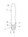
クラフトカッターは、図15に示すように、円板切刃(以下ロータリーブレードと称す)を回転自在に装着するアーム部51と、ハンドル部52と具備して、ロータリーブレード53を押圧しながら、被裁断物の裁断面54上を図15の矢印A方向に走行させることで被裁断物の裁断縁を所望の形状に裁断する構造になっている。このようなクラフトカッター55で被裁断物を裁断する場合には、クラフトカッター55の角度、即ち、アーム部51と裁断面54との成す角度(図15中のθ)を45°に保つことでロータリーブレード53を直線状に移動させ易く、アーム部51と裁断面54との成す角度(図15中のθ)を小さくする程、つまり、アーム部51を寝かせるようにすることで、ロータリーブレード53を小さい回転半径でターンさせる裁断が容易になることが従来から知られていた。
【0003】
しかしながら、従来のクラフトカッター55では、アーム部51がハンドル部52に固定的、或は一体で設けられており、例えば、被裁断物を直線状に裁断する場合には、ロータリーブレード53を直線状の軌跡で走行させるために、図15に示すように、アーム部51を裁断面54に対して45°に保持して裁断していたので、特に、作業者が座った状態では、手首を曲げたり肘を上げる等して長時間の作業が作業者の負担となることがあった。また、一般に、クラフトカッター55には、図16に示すように、ロータリーブレード53の切刃を保護する安全装置としてのガード部56が装備され、このようなクラフトカッター55では、ロータリーブレード53の一方の面側にガード部56を設け、ガード部56をスライド移動することで進退させるか、或はロータリーブレード53自身がスライド移動することでロータリーブレード53の切刃を保護する構造になっており、左利きの作業者には、ガード部56により視界が遮られることで裁断部を目視することが困難となり、裁断作業を難しくさせていた。
【0004】
【発明が解決しようとする課題】
そこで本発明は、上記事情に鑑みてなされたもので、ハンドル部に対してアーム部の角度を任意に位置決めして保持できるようにすることで、作業者の利き腕によらずに所望の裁断が容易にできると共に、安全に操作できるクラフトカッターを提供することを目的とする。
【0005】
【課題を解決するための手段】
上記目的を達成するために、本発明のうち請求項1に記載の発明は、一端にロータリーブレードが装着されて他端がハンドル部に回動可能に軸支されるアーム部と、ロータリーブレードをガードして進退可能に設けられたガード部とを具備し、アーム部がハンドル部に対して支持軸回りに位置決めされて保持されるクラフトカッターにおいて、ガード部を退避させた状態でのアーム部の回動動作を規制するインターロック機構を備えることを特徴とする。
【0006】
ロータリーブレードの切刃が突出した状態でのアーム部の回動動作を規制して、アーム部の位置決め操作を安全に行うことができる。
【0007】
【発明の実施の形態】
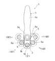
本発明の一実施の形態のクラフトカッターを図1ないし図14に基づいて説明する。まず、本実施の形態のクラフトカッターの概略について説明する。本実施の形態のクラフトカッター1は、図1に示すように、ロータリーブレード2を回転自在に軸支するアーム部3と、アーム部3を保持するハンドル部4とを具備しており、プッシュボタン3aを押すことでアーム部3がアーム部支持軸回りに回動可能となり、45°毎にアーム部3を位置決めして保持する構造になっている。また、クラフトカッター1には、図2に示すように、後述するガード駆動部材5に形成されたダイヤル5aを回転させることでスライド移動されて進出または退避するガード部6が設けられており、ガード部6が退避された状態、即ち、ロータリーブレード2の切刃がガードされていない状態では、プッシュボタン3aをロックしてアーム部3の回動動作を規制する構造になっている。
【0008】
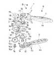
次に、クラフトカッター1の各構成要素について詳細に説明する。ハンドル部4は、図2に示すように、フロントハンドル4aと、バックハンドル4bとでアーム部3を挟持するよう構成されており、フロントハンドル4aに形成されたねじ挿通孔7にねじ8を挿入して、バックハンドル4bに形成されたねじ孔9に螺合して締付けすることで、フロントハンドル4aとバックハンドル4bとが締結される構造になっている。また、フロントハンドル4aには、プッシュボタン3aを挿通するプッシュボタン挿通孔10が形成されており、フロントハンドル4aの裏側には、図3に示すように、プッシュボタン挿通孔10の回りに、後述するアーム部3の歯部3bに整合させるようにして溝部11が形成されている。また、バックハンドル4bの裏側には、図2に示すように、後述するガード駆動部材5に形成されたリング部5bを嵌合させると共に圧縮コイルばね15を収納する環状溝12が形成されている。なお、図2に示す符号13は、ハンドル部4の表面に凸状に形成されたスベリを防止するための小突起で、符号14は、アーム部3を位置決めする際の目安となる角度目盛である。
【0009】
次に、アーム部3について説明する。アーム部3は、図2に示すように、略長丸形状のプレートに、円柱状に形成されたプッシュボタン3aと、該プッシュボタン3aの回りに環状に配置された歯部3bとを一体成型することで構成されており、歯部3bはプッシュボタン3aの回りに45°の角度で等配して設けられている。そして、アーム部3は、それぞれの歯部3bをフロントハンドル4aの裏側に歯部3bと整合して設けた溝部11に噛合させることで、ハンドル部4に対して45°毎に位置決めされるよう構成されている。また、アーム部3は、図2に示すように、バックハンドル4bとガード駆動部材5との間に収納された圧縮コイルばね15により、ガード部6およびガード駆動部材5を介してフロントハンドル4aに向けて付勢されており、アーム部3に形成されたプッシュボタン3aを押して圧縮コイルばね15を圧縮させることで歯部3bが溝部11から外れてアーム部3をアーム部支持軸回りに回動させることができ、アーム部3を所定の位置に位置決めさせてプッシュボタン3aを離すことにより歯部3bが溝部11に噛合い、ハンドル部4に対して45°毎に位置決めされると共に保持される構造になっている。なお、図2に示すように、プッシュボタン3aの裏側には、ガード駆動部材5に形成された支持軸5cを嵌合させる軸孔3cが形成されており、アーム部3は、バックハンドル4bの環状溝12にガード駆動部材5のリング部5bを回転自在に嵌合して、該ガード駆動部材5の支持軸5cに軸孔3cを嵌合することで、支持軸5cに回動自在に軸支されるようにして構成されている。また、アーム部3には、図2に示すように、ロータリーブレード2を軸支するシャフト16を回転自在に支持するシャフト孔3dが形成されている。
【0010】
次に、ガード部6およびガード駆動部材5について説明する。ガード部6は、図2に示すように、略長丸状のプレートの上面に、アーム部3の側面3eに案内させるようにして対向する一対のガイド部6aが形成されると共に、該長丸状のプレートに、ガード駆動部材5のダイヤル5a上面に形成された突起状の係合部5dに係合するようにして係合孔6bが形成されており、ガード駆動部材5のダイヤル5aを回転することで、係合部5dと係合孔6bの斜面6cとの接触部に力F(図4参照)が作用され、ガイド部6aがアーム部3の側面3eに案内されてスライド移動する構造になっている。また、ガード部6には、図2に示すように、ガード駆動部材5に形成された前述した支持軸5cを挿通させるための長孔6dと、ロータリーブレード2を軸支するシャフト16を貫通させるための長孔6eとが設けられ、さらに、ガード部6の下面には、ロータリーブレード2の切刃のハンドル部4側部分をガードするブロック6fが形成されている。なお、図2および図4に示すように、ガード部6の係合孔6bには、該両端部にガード駆動部材5の係合部5dを係止する係止部6gが形成されている。
【0011】
また、クラフトカッター1は、図2に示すように、バックハンドル4bの環状溝12の内側面とガード駆動部5のリング部5bとの間に圧縮コイルばね15を内挿してガード駆動部材5を嵌合して(図5および図6参照)、ガード部6に形成された長孔6dにガード駆動部材5の支持軸5cを挿通させると共にガード駆動部材5の係合部5dをガード部6に形成された係合孔6bに係合し、ガード部6の長孔6dから突出したガード駆動部材5の支持軸5cにアーム部3の軸孔3cを挿入させると共にガード部6に形成された一対のガイド部6aがアーム部3の側面3eに案内されるようにしてアーム部3を配置する。そして、クラフトカッター1は、アーム部3に形成されたプッシュボタン3aにフロントハンドル4aのプッシュボタン挿通孔10を挿通させると共にフロントハンドル4aの溝部11にアーム部3のプッシュボタン3aの回りに配設された歯部3bを噛合させて、フロントハンドル4aとバックハンドル4bとを締結させることにより形成される構造になっている。
【0012】
また、クラフトカッター1は、プッシュボタン3aが押されていない状態では、図7に示すように、ガード駆動部材5とバックハンドル4bとの間に圧縮コイルばね15の圧縮方向の所定の間隔(図7中のH)を有しており、プッシュボタン3aを押すことで、図8に示すように、アーム部3、ガード部6およびガード駆動部材5がストロークされてアーム部3の歯部3bとフロントハンドル4aの溝部11との噛合が外れることにより、アーム部3がハンドル部4に対して回動される構造になっている。なお、アーム部3は、図1に示すように、アーム部3とハンドル部4とが直線状に位置される0°(図9および図10参照)を基準に、45°毎に+90°(図12参照)から−90°(図14参照)まで位置決め可能に形成されている。また、クラフトカッター1には、ガード部6が退避された際のアーム部3の回動動作を規制するインターロック機構が設けられており、図6に示すように、ガード部6を退避させた場合には、ガード駆動部材5のダイヤル5a下面とバックハンドル4bとの間隙17にガード部6に形成されたブロック6fを介在させる構造になっている。そして、この状態でプッシュボタン3aが押圧された際には、ガード部6のブロック6fとバックハンドル4bの先端部が干渉することで、アーム部3、ガード部6およびガード駆動部材5のストロークを規制して、歯部3bと溝部11との噛合を解放させない構造になっている。
【0013】
なお、ロータリーブレード2は、中心部に六角形の軸孔2aを設けており、図2に示すように、該軸孔2aにシャフト16に形成された六角柱状のブレード嵌合部16aを嵌合して、シャフト16をガード部6の長孔6eを挿通させると共にアーム部3のシャフト孔3dにシャフト16の支持部16bを嵌合し、さらに、シャフト16の先端部に形成されたねじ部16cにスプリングワッシャ18を介してねじ部材19を螺合することにより、アーム部3に装着される構造になっている。また、ガード駆動部材5のダイヤル5aの外周部には、所定の間隔で設けられた凹凸が形成されており、これによりダイヤル5aを回転する際の操作性が向上される構造になっている。
【0014】
このような構成において、本実施の形態のクラフトカッター1の作用について説明する。まず、クラフトカッター1のアーム部3を回動させる操作について説明する。
【0015】
(1)まず、アーム部3を位置決めするために、安全装置としてのガード部6を進出させることで、ガード部6が退避されている際のアーム部3の位置決め操作を規制するインターロック機構を解除させる。まず、図4の(b)に示すように、ガード部6が退避された状態でダイヤル5aを時計回りに回転させると、ダイヤル5a上面に形成された係合部5dが係合孔6bの図4中の下方に位置する係止部6gから外れてダイヤル回転軸を中心に回転されることで、ガード部6に形成された係合孔6bの斜面6cにおける係合部5dとの接触部に力F(図4の(c)参照)が作用され、ガード部6がガイド部6aをアーム部3の側面3eに案内されて進出方向にスライド移動され、これにより、ロータリーブレード2の切刃がガード部6にガードされて(図4の(a)および図9参照)、同時にインターロック機構が解除される。なお、ガード部6が所定位置まで進出することで係合部5dが図4中の上方に位置する係止部6gに係止されるので、ガード部の先端部が押されてもガード部6が退避方向に不用意にスライド移動されることがない。
【0016】
(2)次に、プッシュボタン3aを押圧すると、図8に示すように、アーム部3、ガード部6およびガード駆動部材5を介して圧縮コイルばね15が圧縮されることで、アーム部3、ガード部6およびガード駆動部材5が図7中の間隔Hをストロークして、アーム部3の歯部3bとフロントハンドル4aの溝部11との噛合が解放されることにより、プッシュボタン3aが押されている間、アーム部3をハンドル部4に対して回動させることができる。また、アーム部3の歯部3bとフロントハンドル4aの溝部11とは45°毎に噛合するので、所望の角度に位置決めさせてプッシュボタン3aから指を離すことでアーム部3、ガード部6およびガード駆動部材5が圧縮コイルばね15に押し戻されて、アーム部3の歯部3bとフロントハンドル4aの溝部11とが噛合されることによりアーム部3を所望の角度に保持することができる。そして、アーム部3を位置決めして保持した後、図4の(a)に示すように、ガード部6が進出された状態でダイヤル5aを反時計回りに回転させると、ダイヤル5aの上面に形成された係合部5dが係合孔6bの係止部6gから外れてダイヤル回転軸を中心に回転して、ガード部6がガイド部6aをアーム部3の側面3eに案内させて退避方向にスライド移動することで、ロータリーブレード2の切刃が突出されて(図4の(b)および図10参照)被裁断物20(図11ないし図14参照)を裁断することができる。
【0017】
次に、インターロック機構の作用について説明する。前述したように、アーム部3を回動させるには、プッシュボタン3aを押すことにより、アーム部3、ガード部6およびガード駆動部材5を図7に示す間隔Hの間をストロークさせて、アーム部3の歯部3bとフロントハンドル4aの溝部11との噛合を解放させる。本実施の形態のインターロック機構は、ガード部6が退避してロータリーブレード2の切刃が突出されている際に、図6に示すように、ガード駆動部材5とバックハンドル4bとの間隙17にガード部6に形成されたブロック部6fを介在させることで、アーム部3、ガード部6およびガード駆動部材5のストローク、つまり、アーム部3の歯部3bとフロントハンドル4aの溝部11との噛合が解放されるのを阻止することにより、ロータリーブレード2の切刃が突出された状態でのアーム部3の位置決め操作を規制することができる。
【0018】
したがって、本実施の形態のクラフトカッター1は、プッシュボタン3aを押すことでアーム部3に形成された歯部3bとフロントハンドル4aに形成された溝部11との噛合が解放されてアーム部3を回動させることができ、45°毎に歯部3bと溝部11とが噛合されてアーム部3を位置決めして保持することができるので、作業者は、アーム部3を図1および図11に示す45°に位置決め保持してハンドル部4を被裁断物20と平行に握持することにより、アーム部3と被裁断物20との成す角度が45°になり、裁断部を目視しながらの直線状の裁断が容易にでき、また、アーム部3を図1および図12に示す90°に位置決め保持してハンドル部4を被裁断物20と平行に握持することにより、アーム部3と被裁断物20との成す角度が90°になり、ターンを多用した裁断を容易に行うことができる。
【0019】
さらに、作業者が左利きの場合には、アーム部3を図1に示す−45°に位置決め保持してハンドル部4を被裁断物20と平行に握持することにより、ガード部6に視界を遮られることなく裁断部を目視しながらの直線状の裁断が容易にでき、また、アーム部3を図1に示す−90°に位置決め保持してハンドル部4を被裁断物20と平行に握持することにより、ターンを多用した裁断を容易に行うことができる。なお、本実施の形態のクラフトカッター1では、歯部3bをプッシュボタン3aの回りに45°の角度で等配して設けたが、例えば、歯部3bを30°の角度で等配して設けると共に、フロントハンドル4aに溝部11を歯部3bと整合させて設けて、ハンドル部4に対してアーム部3を30°毎に位置決めして保持するよう構成してもよい。また、ロータリーブレード2のガード部6と反対側の側面と裁断面20との間に障害物がないので、直線状に裁断する際には、ロータリーブレード2の端面を定規に沿わせることで、被裁断物20の縁の形状を見栄えよく仕上げることができる。
【0020】
また、本実施の形態のクラフトカッター1は、ガード部6を退避させた状態でのアーム部3の位置決め操作を規制したので、ロータリーブレード2の切刃が突出されている状態でのアーム部3の位置決め操作を規制して、アーム部3の位置決め操作の安全を確保することができる。さらに、ガード部6の係合孔6bの両端部に、係合部5dを係止する係止部6gを形成して、ガード部6が進出および退避された状態で、ガード駆動部材5に形成された係合部5dが係止部6gに係止されるよう構成したので、作業中や収納時に不用意にガード部6がスライド移動するのを防止して、クラフトカッター1の安全を確保することができる。
【0021】
【発明の効果】
本クラフトカッター1によれば、ロータリーブレードが装着されたアーム部を任意に位置決めして保持できるので、例えばアーム部を45°に位置決めして保持することで、直線状の裁断をハンドル部を被裁断物と平行に保った状態で容易に裁断することができ、また、アーム部を90°に位置決めして保持することで、小さなターンを多用した裁断をハンドル部を被裁断物と平行に保った状態で容易に裁断することができる。さらに、作業者が左利きの場合においても、ガード部が視界を遮ることで裁断部が目視しずらいようなことがなく、直線状の裁断およびターンを多用した裁断をハンドル部を被裁断物と平行に保った状態で容易に裁断することができる。
また、ガード部が退避された状態でのアーム部3の位置決め操作を規制したので、ロータリーブレードの切刃が突出されている状態でのアーム部の位置決め操作を防止して、位置決め操作を安全に行うことができる。
【図面の簡単な説明】
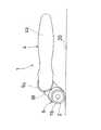
【図1】 本実施の形態のクラフトカッターの説明図である。
【図2】 本実施の形態のクラフトカッターを分解した斜視図である。
【図3】 本実施の形態のクラフトカッターのフロントハンドルに形成された溝部を示す説明図である。
【図4】 本実施の形態のクラフトカッターのガード部がスライド移動する機構を説明するための図で、(a)はガード部が進出された状態を示し、(b)はガード部が退避された状態を示し、(c)は一部の拡大図である。
【図5】 本実施の形態のクラフトカッターにおける、ガード部が進出された状態を示す一部を断面にした側面図である。
【図6】 本実施の形態のクラフトカッターにおける、ガード部が退避された状態を示す一部を断面にした側面図である。
【図7】 本実施の形態のクラフトカッターにおける、プッシュボタンが押される前の状態を示す一部を断面にした側面図である。
【図8】 本実施の形態のクラフトカッターにおける、プッシュボタンが押された状態を示す一部を断面にした側面図である。
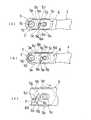
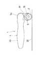
【図9】 本実施の形態のクラフトカッターの正面図で、特に、アーム部の角度が0°でガード部が進出された状態を示す図である。
【図10】 本実施の形態のクラフトカッターの正面図で、特に、アーム部の角度が0°でガード部が退避された状態を示す図である。
【図11】 本実施の形態のクラフトカッターの正面図で、特に、アーム部の角度が45°の状態を示す図である。
【図12】 本実施の形態のクラフトカッターの正面図で、特に、アーム部の角度が90°の状態を示す図である。
【図13】 本実施の形態のクラフトカッターの正面図で、特に、アーム部の角度が−45°の状態を示す図である。
【図14】 本実施の形態のクラフトカッターの正面図で、特に、アーム部の角度が−90°の状態を示す図である
【図15】 従来のクラフトカッターの説明図である。
【図16】 従来のクラフトカッターの説明図で、特に、ガード部を装備したクラフトカッターを示す図である。
【符号の説明】
1 クラフトカッター、2 ロータリーブレード、3 アーム部、4 ハンドル部、6 ガード部[0001]
BACKGROUND OF THE INVENTION
The present invention relates to a craft cutter equipped with a rotary blade, and more particularly to a craft cutter equipped with a safety device.
[0002]
[Prior art]
As shown in FIG. 15, the craft cutter includes an
[0003]
However, in the
[0004]
[Problems to be solved by the invention]
Accordingly, the present invention has been made in view of the above circumstances, and by making it possible to arbitrarily position and hold the angle of the arm portion with respect to the handle portion, a desired cutting can be performed regardless of the operator's dominant arm. An object is to provide a craft cutter that can be easily operated and can be operated safely.
[0005]
[Means for Solving the Problems]
In order to achieve the above object, the invention according to
[0006]
It is possible to safely perform the positioning operation of the arm part by restricting the turning operation of the arm part in a state where the cutting blade of the rotary blade protrudes.
[0007]
DETAILED DESCRIPTION OF THE INVENTION
A craft cutter according to an embodiment of the present invention will be described with reference to FIGS. First, an outline of the craft cutter of the present embodiment will be described. As shown in FIG. 1, the
[0008]
Next, each component of the
[0009]
Next, the
[0010]
Next, the
[0011]
Further, as shown in FIG. 2, the
[0012]
In the state where the
[0013]
The
[0014]
In such a configuration, the operation of the
[0015]
(1) First, an interlock mechanism that restricts the positioning operation of the
[0016]
(2) Next, when the
[0017]
Next, the operation of the interlock mechanism will be described. As described above, in order to rotate the
[0018]
Therefore, in the
[0019]
Further, when the operator is left-handed, the
[0020]
In addition, since the
[0021]
【The invention's effect】
According to the
Further , since the positioning operation of the
[Brief description of the drawings]
FIG. 1 is an explanatory diagram of a craft cutter according to an embodiment of the present invention.
FIG. 2 is an exploded perspective view of the craft cutter of the present embodiment.
FIG. 3 is an explanatory view showing a groove formed in the front handle of the craft cutter according to the present embodiment.
FIGS. 4A and 4B are diagrams for explaining a mechanism in which a guard part of the craft cutter according to the present embodiment slides, in which FIG. 4A shows a state in which the guard part has advanced, and FIG. 4B shows that the guard part is retracted. (C) is a partially enlarged view.
FIG. 5 is a side view, partly in section, showing a state in which the guard portion has advanced in the craft cutter of the present embodiment.
FIG. 6 is a side view, partly in section, showing a state in which the guard portion is retracted in the craft cutter of the present embodiment.
FIG. 7 is a side view, partly in section, showing a state before the push button is pressed in the craft cutter of the present embodiment.
FIG. 8 is a side view, partly in section, showing a state in which a push button is pressed in the craft cutter of the present embodiment.
FIG. 9 is a front view of the craft cutter according to the present embodiment, and particularly shows a state where the guard portion is advanced when the angle of the arm portion is 0 °.
FIG. 10 is a front view of the craft cutter according to the present embodiment, and particularly shows a state where the arm portion has an angle of 0 ° and the guard portion is retracted.
FIG. 11 is a front view of the craft cutter according to the present embodiment, and particularly shows a state where the angle of the arm portion is 45 °.
FIG. 12 is a front view of the craft cutter according to the present embodiment, and particularly shows a state where the angle of the arm portion is 90 °.
FIG. 13 is a front view of the craft cutter according to the present embodiment, and particularly shows a state where the angle of the arm portion is −45 °.
FIG. 14 is a front view of the craft cutter of the present embodiment, and particularly shows a state where the angle of the arm portion is −90 °. FIG. 15 is an explanatory diagram of a conventional craft cutter.
FIG. 16 is an explanatory diagram of a conventional craft cutter, and particularly shows a craft cutter equipped with a guard portion.
[Explanation of symbols]
1 Craft cutter, 2 Rotary blade, 3 Arm part, 4 Handle part, 6 Guard part
Claims (1)
Translated fromJapanesePriority Applications (6)
| Application Number | Priority Date | Filing Date | Title |
|---|---|---|---|
| JP30905099AJP3893578B2 (en) | 1999-10-29 | 1999-10-29 | Craft cutter |
| US09/691,111US6460254B1 (en) | 1999-10-29 | 2000-10-19 | Cutter |
| DE60000854TDE60000854T2 (en) | 1999-10-29 | 2000-10-24 | cutter |
| EP00122352AEP1095743B1 (en) | 1999-10-29 | 2000-10-24 | Cutter |
| AU69565/00AAU771105B2 (en) | 1999-10-29 | 2000-10-26 | Cutter |
| CNB001347373ACN1195609C (en) | 1999-10-29 | 2000-10-27 | Cutter |
Applications Claiming Priority (1)
| Application Number | Priority Date | Filing Date | Title |
|---|---|---|---|
| JP30905099AJP3893578B2 (en) | 1999-10-29 | 1999-10-29 | Craft cutter |
Publications (2)
| Publication Number | Publication Date |
|---|---|
| JP2001120860A JP2001120860A (en) | 2001-05-08 |
| JP3893578B2true JP3893578B2 (en) | 2007-03-14 |
Family
ID=17988278
Family Applications (1)
| Application Number | Title | Priority Date | Filing Date |
|---|---|---|---|
| JP30905099AExpired - Fee RelatedJP3893578B2 (en) | 1999-10-29 | 1999-10-29 | Craft cutter |
Country Status (6)
| Country | Link |
|---|---|
| US (1) | US6460254B1 (en) |
| EP (1) | EP1095743B1 (en) |
| JP (1) | JP3893578B2 (en) |
| CN (1) | CN1195609C (en) |
| AU (1) | AU771105B2 (en) |
| DE (1) | DE60000854T2 (en) |
Families Citing this family (31)
| Publication number | Priority date | Publication date | Assignee | Title |
|---|---|---|---|---|
| US6675485B1 (en)* | 2002-09-27 | 2004-01-13 | Shih-Chin Shih | Artistic knife with adjustable handle |
| JP4272032B2 (en)* | 2003-10-22 | 2009-06-03 | クロバー株式会社 | Hand tool with disk-shaped blade |
| US20080282551A1 (en)* | 2004-10-15 | 2008-11-20 | Stravitz David M | Cutting Devices |
| US7591072B2 (en)* | 2004-10-15 | 2009-09-22 | Stravitz David M | Cutting devices |
| US7231718B2 (en)* | 2005-01-28 | 2007-06-19 | James Timothy Outen | Multi-position locking tool |
| US7415915B2 (en)* | 2005-04-05 | 2008-08-26 | Elmer's Products, Inc. | Cutting system having an interchangeable rotary blade cartridge |
| US7434319B2 (en)* | 2005-08-01 | 2008-10-14 | Chen Lin Tsai-Lian | Circular cutter |
| US7290340B2 (en)* | 2005-08-05 | 2007-11-06 | Tsai-Lian Chen Lin | Circular cutter |
| NL1033944C2 (en)* | 2007-06-06 | 2008-12-09 | Gijsbert Van Dusschoten | Hairdresser's tool. |
| US20100071522A1 (en)* | 2008-09-22 | 2010-03-25 | Pattie Otto | Universal Rotary Blade for Fabric Embellishment |
| US20100263219A1 (en)* | 2008-12-17 | 2010-10-21 | Kempker Jeffrey A | Tool with ergonomic handle and replaceable cutter head |
| USD639631S1 (en) | 2009-11-18 | 2011-06-14 | Klever Kutters Llc | Handle |
| CN102092050B (en)* | 2009-12-11 | 2012-09-05 | 钟敏 | Rotary cutter |
| US8950077B2 (en) | 2010-09-01 | 2015-02-10 | Elwood Dean Quimby | Utility knife apparatus with blades having multiple cutting portions |
| US8978257B2 (en) | 2010-09-01 | 2015-03-17 | Elwood Dean Quimby | Utility knife with a blade having multiple cutting portions |
| US9009981B2 (en) | 2010-09-01 | 2015-04-21 | Elwood Dean Quimby | Utility knife blades having multiple cutting portions and securing connections |
| US8667696B2 (en)* | 2010-10-23 | 2014-03-11 | Ronald J. Zdroik | Rotary cutter |
| US8549754B2 (en)* | 2011-03-21 | 2013-10-08 | Hubert J. Bung | Rotating head multi-angled cutting knife |
| USD673440S1 (en) | 2011-04-28 | 2013-01-01 | Klever Kutter, Llc | Cutter |
| US20120304472A1 (en)* | 2011-06-02 | 2012-12-06 | Simon Medhurst | Multi-angle hand held cutting tool |
| US8590163B1 (en)* | 2011-10-28 | 2013-11-26 | Gracewood Sales, LLC | Rotary cutter guard and safety light assembly |
| US8984736B2 (en)* | 2012-08-10 | 2015-03-24 | Therapeutic Recreation Systems, Inc. | Prosthetic device for handling a ball |
| US10022146B2 (en) | 2015-05-29 | 2018-07-17 | Exsurco Medical, Inc. | Power operated rotary excision tool |
| US10537356B2 (en) | 2014-06-16 | 2020-01-21 | Exsurco Medical, Inc. | Power operated rotary excision tool |
| US9186171B2 (en)* | 2012-09-07 | 2015-11-17 | Exsurco Medical, Inc. | Power operated debridement tool with disk knife blade |
| USD907205S1 (en) | 2012-09-07 | 2021-01-05 | Exsurco Medical, Inc. | Power operated rotary excision tool |
| US9278459B2 (en)* | 2012-12-17 | 2016-03-08 | Fiskars Brands, Inc. | Rotary blade replacement apparatus and method |
| US20190337175A1 (en)* | 2018-05-01 | 2019-11-07 | Pei-Keng Liu | Cutting device |
| CN110576457A (en)* | 2018-06-11 | 2019-12-17 | 杭州巨星科技股份有限公司 | Manual knife with scissor function |
| US11833701B2 (en)* | 2021-04-30 | 2023-12-05 | Fiskars Finland Oy Ab | Blade receiver assembly and cutting device |
| WO2023015177A1 (en) | 2021-08-03 | 2023-02-09 | Gracewood Management, Inc. | Rotary cutter |
Family Cites Families (13)
| Publication number | Priority date | Publication date | Assignee | Title |
|---|---|---|---|---|
| US3711945A (en) | 1971-05-12 | 1973-01-23 | R Cronheim | Pie cutter and server |
| US4100677A (en)* | 1977-02-15 | 1978-07-18 | Jeff Adolph L | Precision cutting tool |
| USRE32501E (en)* | 1981-09-29 | 1987-09-15 | Okada Kogyo Kabushiki Kaisha | Rotary cutter |
| DE9003291U1 (en) | 1990-03-21 | 1990-07-26 | Weschenfelder, Ralf, 7529 Forst | Universal hand cutter |
| US5355588A (en) | 1992-01-15 | 1994-10-18 | Fiskars Inc. | Rotary cutting blade assembly for a hand-held cutter |
| US5144749A (en) | 1992-03-30 | 1992-09-08 | Chen Chien Tang | Utility knife |
| US5493781A (en)* | 1992-04-17 | 1996-02-27 | Kai R&D Center Co., Ltd. | Cutter |
| GB9314163D0 (en)* | 1993-07-08 | 1993-08-18 | Black & Decker Inc | Chop/table saw arrangement |
| US5463942A (en)* | 1994-02-08 | 1995-11-07 | Regal Ware, Inc. | Motorized tool for slicing and tenderizing foods and method |
| US5400512A (en)* | 1994-03-01 | 1995-03-28 | Brush; Jerry L. | Windshield molding removing knife |
| US5765289A (en)* | 1996-12-20 | 1998-06-16 | Fiskars Inc. | Rotary cutter |
| JP3343506B2 (en)* | 1998-04-16 | 2002-11-11 | 株式会社貝印刃物開発センター | Protective member locking device for circular blade type cutter |
| US6282794B1 (en)* | 1998-05-27 | 2001-09-04 | Young-Keun Cho | Rotary cutter with a blade cartridge |
- 1999
- 1999-10-29JPJP30905099Apatent/JP3893578B2/ennot_activeExpired - Fee Related
- 2000
- 2000-10-19USUS09/691,111patent/US6460254B1/ennot_activeExpired - Fee Related
- 2000-10-24EPEP00122352Apatent/EP1095743B1/ennot_activeExpired - Lifetime
- 2000-10-24DEDE60000854Tpatent/DE60000854T2/ennot_activeExpired - Lifetime
- 2000-10-26AUAU69565/00Apatent/AU771105B2/ennot_activeCeased
- 2000-10-27CNCNB001347373Apatent/CN1195609C/ennot_activeExpired - Fee Related
Also Published As
| Publication number | Publication date |
|---|---|
| DE60000854D1 (en) | 2003-01-09 |
| AU771105B2 (en) | 2004-03-11 |
| AU6956500A (en) | 2001-05-03 |
| CN1295908A (en) | 2001-05-23 |
| JP2001120860A (en) | 2001-05-08 |
| EP1095743B1 (en) | 2002-11-27 |
| DE60000854T2 (en) | 2003-08-28 |
| CN1195609C (en) | 2005-04-06 |
| US6460254B1 (en) | 2002-10-08 |
| EP1095743A1 (en) | 2001-05-02 |
Similar Documents
| Publication | Publication Date | Title |
|---|---|---|
| JP3893578B2 (en) | Craft cutter | |
| US6272757B1 (en) | Adjustable guide shoe for reciprocating saw | |
| US6688203B2 (en) | Circular sawing machine having indication device | |
| JP3207865B2 (en) | Portable circular saw | |
| US3667122A (en) | Safety razor blade holder | |
| GB2430913A (en) | Worktable with pivotable guide assembly | |
| DE102012217532B4 (en) | Saw arrangement | |
| CN102802877B (en) | Powered tool | |
| US11766803B2 (en) | Guide ruler for portable machining apparatus | |
| US5140754A (en) | Power tool protective hood positioning system and method of manufacturing the same | |
| JP2013508181A (en) | Polishing machine installed in the bar | |
| US4206672A (en) | Cutting tool jig with cutter guard | |
| CN112839762B (en) | Tube cutting device | |
| JP4898354B2 (en) | Chainsaw | |
| US20120118122A1 (en) | Fall-out preventing structure for fixing device of guard member in cutting machine | |
| DE10048675A1 (en) | Hand tool | |
| CN105522218B (en) | Power tool | |
| KR102649664B1 (en) | Cutting device | |
| JP2007118230A (en) | Cutting machine | |
| JP4368555B2 (en) | Electric tool | |
| WO2022134209A1 (en) | Portable chainsaw | |
| JP2022046090A (en) | Fixture, set of fixtures, and set of accessories used with portable processing machine | |
| JP2011143525A (en) | Cutting tool | |
| JPH09314401A (en) | End face processing equipment for pipes | |
| JP4541862B2 (en) | Cutting machine |
Legal Events
| Date | Code | Title | Description |
|---|---|---|---|
| A621 | Written request for application examination | Free format text:JAPANESE INTERMEDIATE CODE: A621 Effective date:20051202 | |
| A977 | Report on retrieval | Free format text:JAPANESE INTERMEDIATE CODE: A971007 Effective date:20061005 | |
| A131 | Notification of reasons for refusal | Free format text:JAPANESE INTERMEDIATE CODE: A131 Effective date:20061018 | |
| A521 | Written amendment | Free format text:JAPANESE INTERMEDIATE CODE: A523 Effective date:20061030 | |
| TRDD | Decision of grant or rejection written | ||
| A01 | Written decision to grant a patent or to grant a registration (utility model) | Free format text:JAPANESE INTERMEDIATE CODE: A01 Effective date:20061122 | |
| A61 | First payment of annual fees (during grant procedure) | Free format text:JAPANESE INTERMEDIATE CODE: A61 Effective date:20061201 | |
| R150 | Certificate of patent or registration of utility model | Free format text:JAPANESE INTERMEDIATE CODE: R150 | |
| FPAY | Renewal fee payment (event date is renewal date of database) | Free format text:PAYMENT UNTIL: 20101222 Year of fee payment:4 | |
| FPAY | Renewal fee payment (event date is renewal date of database) | Free format text:PAYMENT UNTIL: 20111222 Year of fee payment:5 | |
| FPAY | Renewal fee payment (event date is renewal date of database) | Free format text:PAYMENT UNTIL: 20111222 Year of fee payment:5 | |
| FPAY | Renewal fee payment (event date is renewal date of database) | Free format text:PAYMENT UNTIL: 20121222 Year of fee payment:6 | |
| FPAY | Renewal fee payment (event date is renewal date of database) | Free format text:PAYMENT UNTIL: 20131222 Year of fee payment:7 | |
| FPAY | Renewal fee payment (event date is renewal date of database) | Free format text:PAYMENT UNTIL: 20131222 Year of fee payment:7 | |
| FPAY | Renewal fee payment (event date is renewal date of database) | Free format text:PAYMENT UNTIL: 20141222 Year of fee payment:8 | |
| LAPS | Cancellation because of no payment of annual fees |