JP3890927B2 - COMMUNICATION DEVICE MANAGING OTHER NODES AND COMMUNICATION DEVICE MANAGED BY OTHER NODES - Google Patents
COMMUNICATION DEVICE MANAGING OTHER NODES AND COMMUNICATION DEVICE MANAGED BY OTHER NODESDownload PDFInfo
- Publication number
- JP3890927B2 JP3890927B2JP2001220895AJP2001220895AJP3890927B2JP 3890927 B2JP3890927 B2JP 3890927B2JP 2001220895 AJP2001220895 AJP 2001220895AJP 2001220895 AJP2001220895 AJP 2001220895AJP 3890927 B2JP3890927 B2JP 3890927B2
- Authority
- JP
- Japan
- Prior art keywords
- node
- upper layer
- communication
- lower layer
- network
- Prior art date
- Legal status (The legal status is an assumption and is not a legal conclusion. Google has not performed a legal analysis and makes no representation as to the accuracy of the status listed.)
- Expired - Lifetime
Links
Images


Classifications
- H—ELECTRICITY
- H04—ELECTRIC COMMUNICATION TECHNIQUE
- H04L—TRANSMISSION OF DIGITAL INFORMATION, e.g. TELEGRAPHIC COMMUNICATION
- H04L41/00—Arrangements for maintenance, administration or management of data switching networks, e.g. of packet switching networks
- H—ELECTRICITY
- H04—ELECTRIC COMMUNICATION TECHNIQUE
- H04L—TRANSMISSION OF DIGITAL INFORMATION, e.g. TELEGRAPHIC COMMUNICATION
- H04L49/00—Packet switching elements
- H04L49/60—Software-defined switches
- H04L49/602—Multilayer or multiprotocol switching, e.g. IP switching
- H—ELECTRICITY
- H04—ELECTRIC COMMUNICATION TECHNIQUE
- H04L—TRANSMISSION OF DIGITAL INFORMATION, e.g. TELEGRAPHIC COMMUNICATION
- H04L9/00—Cryptographic mechanisms or cryptographic arrangements for secret or secure communications; Network security protocols
- H04L9/40—Network security protocols
- H—ELECTRICITY
- H04—ELECTRIC COMMUNICATION TECHNIQUE
- H04L—TRANSMISSION OF DIGITAL INFORMATION, e.g. TELEGRAPHIC COMMUNICATION
- H04L49/00—Packet switching elements
- H04L49/35—Switches specially adapted for specific applications
- H04L49/351—Switches specially adapted for specific applications for local area network [LAN], e.g. Ethernet switches
Landscapes
- Engineering & Computer Science (AREA)
- Computer Networks & Wireless Communication (AREA)
- Signal Processing (AREA)
- Computer Security & Cryptography (AREA)
- Small-Scale Networks (AREA)
- Information Transfer Systems (AREA)
Description
Translated fromJapanese【0001】
【発明の属する技術分野】
本発明は、統括ノードと末端ノードを持つ通信装置に関し、より詳しくは、他のノードを管理することが出来る統括ノードと、該統括ノードによって管理される末端ノードに関する。
【0002】
【従来の技術】
大容量高速転送が可能なシリアルインターフェイスの規格として、IEEE1394が知られている。このIEEE1394規格に準拠したインターフェイス又は該インターフェイスを有する機器(以下、まとめてIEEE1394デバイスと呼ぶ)は、それぞれが1つのノードとしてハードウェアからなるIEEE1394バスプロトコル(下位層)と、その上にデバイスのコントロールやアイソクロナス転送のコントロールなどのプロトコル(上位層)をソフトウェアで実装している。
【0003】
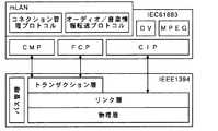
図9は、mLAN(商標)上位層を実装した一般的なAV(オーディオ・ビジュアル)装置のプロトコルスタックの一例を表す概念図である。mLANとは、IEEE1394規格に準拠し、その上位に位置するアプリケーションで、音楽のためのデジタルネットワークシステムである。
【0004】
下位層は、例えば、物理層(Physical Layer)、リンク層(Link Layer)、トランザクション層(Transaction Layer)及びバス管理(Serial Bus Management)の各層を含んで構成される。
【0005】
物理層では、物理的・電気的なインターフェイスが規定されている。物理層は、一般的にハードウェアで構成されている。
【0006】
リンク層では、サブアクションと呼ばれる一方向の転送サービス、及びパケットの送受信に関するサービス(Packet Handler)が提供される。リンク層も、物理層と同様、一般的にはハードウェアで構成される。リンク層では、例えば、アシンクロナス(非同期)転送(Asyncronous Transmission)、及びアイソクロナス転送(Isochronous Transmission)に関するサービスが提供される。
【0007】
また、特に、アイソクロナス転送については、オーディオ信号やビデオ信号等の高速な処理を必要とする信号を扱うので、ハードウェアであるリンク層で、全てのサービスを提供している。
【0008】
トランザクション層では、アシンクロナス転送に関する処理が行われる。トランザクションとは、要求−応答型のデータ転送であり、読み込み(Read)トランザクション、書き込み(Write)トランザクション、ロック(Lock)トランザクションの三種類がある。
【0009】
読み込みトランザクションは、ターゲットの特定アドレス空間からデータの読み出しを行うためのトランザクションであり、書き込みトランザクションは、ターゲットの特定アドレス空間へのデータの書き込みを行うためのトランザクションである。ロックトランザクションは、参照データに基づき、ターゲット上の特定アドレス空間のデータを更新するためのトランザクションである。
【0010】
バス管理は、バス上の資源を集中的に管理するためのモジュールである。バス管理では、電源供給の管理、トポロジーマップとスピードマップの管理、アイソクロナス・リソースの管理等が行われる。
【0011】
上位層は、下位層及びノード全体を管理するためのソフトウェアであり、例えば、1394AVプロトコル(IEC−61883)、及びmLAN上位層により構成されている。
【0012】
1394AVプロトコルでは、アイソクロナス・パケットのデータ内容を表現するためのCIP(Common Isochronous Packet)フォーマット、仮想的な「プラグ」を定義してコネクションの管理を行うためのCMP(Connection Management Protocol)、IEEE1394バスに接続される他の機器を管理するためのFCP(Function Control Protocol)等が定義されている。
【0013】
mLAN上位層は、IEEE1394規格上でオーディオ/音楽情報の転送を行うためのプロトコル階層である。mLAN上位層は、オーディオ/音楽情報転送プロトコルとコネクション管理プロトコルから構成されており、どちらのプロトコルも1394AVプロトコルに準拠している。
【0014】
オーディオ/音楽情報転送プロトコルは、CIPの定義にオーディオ/音楽情報の転送のためのフォーマットを追加するものである。コネクション管理プロトコルは、CMPをインテリジェント化し、各ノード上での自律的なコネクション管理を行うためのプロトコルである。
【0015】
【発明が解決しようとする課題】
これら上位層及び下位層は、その機能に多少の差はあっても、IEEE1394バスに接続される全てのIEEE1394デバイスに実装されている。
【0016】
上位層は、下位層に比べて複雑であるため、上位層を実装するために必要なハードウェア資源が下位層に比べて多くなってしまう。このため、全てのIEEE1394デバイスに、上位層を実装すると製造コストが上がってしまう。
【0017】
また、上位層は、下位層に比べてユーザインターフェイスに関係する場合が多いため、ユーザからの改善要求をフィードバックする機会が多くなり、新しい仕様に容易に変更できる構造が望ましいが、全てのIEEE1394デバイスの上位層を、容易にアップグレードできる構造にすると製造コストを上げる要因になってしまう。
【0018】
本発明の目的は、製造コストをおさえたIEEE1394規格に準拠した機器を提供することである。
【0019】
また、本発明の他の目的は、他のノードを管理することができるIEEE1394規格に準拠した機器を提供することである。
【0020】
【課題を解決するための手段】
本発明の一観点によれば、それぞれ他のノードと信号を送受信する通信手段を有する下位層を備えた複数のノードが接続されたネットワークにおける1つのノードを構成する通信装置は、前記下位層を管理する第1の上位層と、前記ネットワークに接続された他のノードのうち特定の末端ノードの下位層を前記ネットワーク越しに管理する第2の上位層と、管理対象である前記特定の末端ノードの機能に関する情報を記憶する記憶手段とを備えたことを特徴とする。
【0022】
さらに、本発明の他の観点によれば、通信システムは、ネットワークに接続された他のノードと信号を送受信する通信手段を有する下位層と、該下位層に対する信号を前記通信手段が受信した場合には、該信号に応じた処理を行う処理手段と、前記通信手段が上位層に対する信号を受信したときは、上位層を備えていないことを前記他のノードに通知する通知手段とを有し、前記ネットワーク上の1つのノードを構成する末端ノードと、前記ネットワークに接続された他のノードと信号を送受信する通信手段を有する下位層と、該下位層を管理する第1の上位層と、前記末端ノードの下位層を前記ネットワークを介して管理する第2の上位層とを有し、前記ネットワーク上の1つのノードを構成する統括ノードとを有する。
【0023】
【発明の実施の形態】
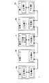
図1は、本発明の実施例によるIEEE1394バス1の一例を表すブロック図である。
【0024】
本発明の実施例によるIEEE1394バス1は、例えば、上位層及び下位層を実装する一般ノード2a及び一般ノード2b、上位層を持たない末端ノード3a、上位層及び下位層及び他のノード(末端ノード3a、3b)の上位層を実装する統括ノード4をIEEE1394ケーブルで接続することにより構成される。
【0025】
一般ノード2a及び2bは、IEEE1394インターフェイスを有する電子楽器、音響機器、AV機器、パーソナルコンピュータ、又は各種外部記憶装置等のいずれか1つである。一般ノード2a及び2bは、それぞれ上位層A、下位層A、上位層E、下位層Eを実装している。
【0026】
末端ノード3aは、IEEE1394インターフェイスを有する電子楽器、音響機器、AV機器、パーソナルコンピュータ、又は各種外部記憶装置等のいずれか1つであり、例えば、パワードスピーカ等である。末端ノード3aは、上位層を実装しておらず、下位層Bのみを実装している。末端ノード3aは、上位層を実装していないので、単体では、一般ノード2a又は2bと上位層で定義されるプロトコルによる正常な通信を行うことが出来ない。
【0027】
このように、末端ノード3aは、上位層を実装していないので、通常上位層で処理される1394AVプロトコルに基づくコマンドやmLAN規格に基づくコマンドを単体で処理することは出来ないが、各種トランザクションやアイソクロナス転送などは下位層に実装されているので、単体で処理することが出来る。
【0028】
例えば、末端ノード3aが、パワードスピーカである場合は、発音するための音声信号等は、通常アイソクロナス転送により送信されるので、下位層だけで処理することが出来る。一方、受信チャンネル等のコネクションの設定、ボリュームコントロールなどは、通常、上位層によりコマンドが受付けられ、該コマンドに対応する機能レジスタに書き込みが行われるので、下位層しか持たない末端ノード3a単体では処理することが出来ない。
【0029】
末端ノード3aは、自ノードが末端ノードであって、それを統括するノードに必要な上位層の種類を特定するIDを、後述のCSR(Control andStatus Registers)メモリに記録している。また、現在、自ノードを統括している統括ノードのGUID(Grobal Unique Identifier)をCSRメモリに記録する。
【0030】
統括ノード4は、IEEE1394インターフェイスを有する電子楽器、音響機器、AV機器、パーソナルコンピュータ、又は各種外部記憶装置等のいずれか1つであり、例えば外部記憶装置を有するパーソナルコンピュータにより構成される。統括ノード4は、下位層Cと、自身の上位層Cに加えて、末端ノード3a及び3bの下位層を管理するための上位層B及びDを実装している。これらの上位層B及びDが、末端ノード3a及び3bの上位層の代理をして、一般ノード2a又は2bと、上位層で定義されるプロトコルによる通信を行うことが出来る。
【0031】
統括ノード4は、自己が統括することが出来る末端ノードのGUIDを、該末端ノードを管理するためのソフトウェア(上位層)と関連付けて記録している。
【0032】
末端ノード3bは、末端ノード3aとほぼ同様の構成であるが、上位層D’及び下位層Dを実装している。末端ノード3bは、実装している上位層D’の機能を停止して、統括ノード4の上位層Dにより管理することができる。なお、末端ノード3bの上位層D’を、一部の機能しか管理しないものにして、不足する機能を統括ノード4の上位層Dにより管理してもよい。実装している上位層D’の機能は、外部からのコマンドにより実行又は停止することが出来る。
【0033】
末端ノード3bも、末端ノード3aと同様に、自ノードが末端ノードであって、それを統括するノードに必要な上位層の種類を特定するIDを、CSRメモリに記録している。また、実装している上位層D’の機能を停止する場合には、現在、自ノードを統括している統括ノードのGUIDをCSRメモリに記録する。
【0034】
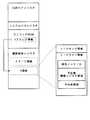
図2は、本実施例による末端ノード3a(又は3b)のCSRメモリの一例を表す概念図である。
【0035】
末端ノード3a(又は3b)のCSRメモリは、例えば、CSRコアレジスタ、シリアルバスレジスタ、Yアドレス情報を有するコンフィグROM、及びAV/C領域とY領域を有する機器固有レジスタを含んで構成される。
【0036】
CSRコアレジスタ及びシリアルバスレジスタは周知のIEEE1394デバイスのものと同様の構成である。
【0037】
Yアドレス情報は、他のノード(特に統括ノード)に対して、Y領域に含まれるリードオンリ領域、リードライト領域、及びリードライト領域内の統括ノードID、下位層機能レジスタ領域、その他領域のアドレスを公開している。
【0038】
統括ノードIDには、自機を管理している統括ノードのGUIDを記録する。
【0039】
統括ノードIDにGUIDを記録されたノード(統括ノード)は、このYアドレス情報を読み込むことにより、末端ノードを管理するために必要なレジスタのアドレスを検出することが出来る。
【0040】
また、統括ノードIDにGUIDを記録されたノードのみが機器固有レジスタに対する書き込みを出来るように設定してもよい。このようにすると、統括ノードIDにGUIDを記録されていない統括ノードが同一バス上に存在する場合にも、統括ノード同士が競合する事を防止できる。
【0041】
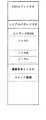
図3は、本実施例による統括ノード4のCSRメモリの一例を表す概念図である。
【0042】
統括ノード4のCSRメモリは、例えば、CSRコアレジスタ、シリアルバスレジスタ、コンフィグROM、及びAV/C領域を有する機器固有レジスタを含んで構成される。
【0043】
CSRコアレジスタ及びシリアルバスレジスタは周知のIEEE1394デバイスのものと同様の構成であり、その他の構成についても図2の末端ノード3a(又は3b)のCSRメモリとほぼ同様である。
【0044】
この統括ノード4のCSRメモリの特徴は、コンフィグROM内に自身の情報以外に、管理下にある末端ノードの機能に関する情報を記録していることである。これらの管理下にある末端ノードの機能をコンフィグROMに追加することにより、他のノードからは、統括ノードが末端ノードの機能を有しているように見える。
【0045】
図4は、一般ノード2aと一般ノード2b間の通信を表すブロック図である。
【0046】
まず、末端ノード3aが一般ノード2a(送信側)から、上位層Eの機能に対応するアドレスに対するコマンド書き込み命令(パケット1)を受信する。次に、一般ノード2b(受信側)の下位層Eは、上記書き込み命令に基づき、上位層Eの機能に対するアドレスへのコマンド書き込みを実行する。
【0047】
その後、一般ノード2bの上位層Eは、書き込み命令(パケット1)を受付け、上記コマンドに対応するレジスタ(機能レジスタ)への書き込み命令を下位層Eに対して行う。すなわち、上位層Eは、受信したコマンドを解釈し、当該コマンドが管理しようとする機能に対応する下位層Eのレジスタ(機能レジスタ)に、当該コマンドの内容に応じた制御データを書き込む。以上により、下位層Eは、レジスタに書き込まれた制御データに基づいて一般ノード2aの送信したコマンドに対応した動作を行うことが出来る。
【0048】
正常に書き込みが行われたら、一般ノード2bの下位層Eは、一般ノード2aに対して、上記書き込み命令が正常に行われたことを示すパケット2を送信する。
【0049】
このように、上位層を持つノード同士では、上位層を介すことにより、機能レジスタへの書き込みを行い、お互いに他の機器を管理することが出来る。
【0050】
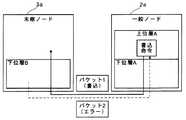
図5は、本実施例による一般ノード2aと末端ノード3a間の通信を表すブロック図である。なお、この例では統括ノード4がIEEE1394バス1上に存在しないものとする。
【0051】
まず、一般ノード2a(送信側)から、上位層の機能に対応するアドレスに対するコマンド書き込み命令(パケット1)を受信する。次に、末端ノード3a(受信側)の下位層Bは、上記書き込み命令に応じて、書き込みを実行しようとする。しかし、末端ノード3aには、上位層が実装されていないため、該上位層の機能に対応するアドレスが存在せず、下位層Bは、エラー(パケット2)を一般ノード2aに対して送信する。すなわち、末端ノード3aには上位層がないので、受信したパケット2に応じたコマンドの書き込みは失敗し、したがって、そのコマンドに応じた下位層Bに対する制御が行われることはない。
【0052】
このように、末端ノード3aは、上位層の機能に対応するコマンドに対してエラーを帰すので、末端ノード3aが上位層を実装してないことがわかる。
【0053】
そこで、本実施例では、図6に示すように統括ノード4が、末端ノード3aの上位層を実装して、一般ノード2aとの通信を代理して行う。
【0054】
図6は、本実施例による統括ノード4を介した一般ノード2aと末端ノード3a間の通信を表すブロック図である。なお、統括ノード4は、後述の末端ノード管理設定処理により、末端ノード3aを管理するように設定されている。
【0055】
まず、統括ノード4の下位層Cは、一般ノード2a(要求元)から、末端ノード3aの上位層Bの機能に対応するアドレスに対するコマンド書き込み命令(パケット1)を受信する。
【0056】
次に、統括ノード4の下位層Cは、該受信した書き込み命令に基づき、上位層Bの機能に対応するアドレスに対してコマンドを書き込む。その後、上位層Bは、該コマンドで指示された機能に対応する末端ノード3a内の下位層Bの機能レジスタのアドレスを検出し、該検出したアドレスに対する該コマンドに応じた制御データの書き込み命令(パケット2)を末端ノード3aに対して送信する。
【0057】
その後、末端ノード3aの下位層Bは、受け取った書き込み命令(パケット2)を実行し、すなわち、下位層Bの該機能レジスタに相当するアドレスへ該制御データを書き込み、その結果(パケット3)を、統括ノード4に対して送信する。下位層Bは、書き込まれた制御データに基づいて、一般ノード2aが統括ノード4の上位層Bに対して送信したコマンドに対応した動作を行う。
【0058】
末端ノード3aからの処理結果(パケット3)を受信した統括ノードは、要求の発行元である(コマンドを送ってきた)一般ノード2aに対して、当初のコマンドに対する応答(パケット4)を送信する。
【0059】
一般ノード2aは、統括ノード4からの応答(パケット4)を受信して、処理が正常に行われたことを認識する。
【0060】
このように、統括ノード4が、本来末端ノードの上位層が果たすべき役割を代理して行い、上位層で処理すべき信号を下位層で処理できるフォーマットで末端ノードに送信してやることにより、上位層を持たない末端ノードに対するコマンドの書き込み等を行うことが出来る。
【0061】
図7は、本実施例の統括ノード4における末端ノードの管理設定処理を表すフローチャートである。この末端ノード管理設定処理は、通常のバスリセット(新たなノードがバスに接続されたり、これまで接続されていたノードがバスから外される等のトポロジー変化が起きた時に発生する)が実行されるごとに起動される。
【0062】
ステップSA1では、末端ノード管理設定処理を開始して次のステップSA2に進む。
【0063】
ステップSA2では、末端ノード管理処理を初期化する。ここでは、例えば、統括ノードのコンフィグROM内に記載された末端ノードの上位層に対応する機能等をクリアする。その後、次のステップSA3に進む。
【0064】
ステップSA3では、管理すべき末端ノードのGUIDを書き換え可能な記憶装置から読み出す。本実施例の統括ノードには、以下の説明の便宜上、予め管理すべき末端ノードのGUIDが1つ記録されているものとする。なお、実際には、1つとは限らず、複数である場合もあるし、1つもない場合もある。
【0065】
また、管理すべき末端ノードのGUIDは、ユーザが入力するようにしてもよい。また、図5に示したように末端ノードに上位層の機能に対応するアドレスに対する書き込み命令を送信し、エラーが帰された末端ノードのGUIDを末端ノードのコンフィグROMから読み出すようにしてもよい。管理すべき末端ノードのGUIDを読み出したら、次のステップSA4に進む。
【0066】
ステップSA4では、IEEE1394バス1に接続されたノードのGUIDを読み出す。なお、ここでは1つのノードのGUIDを読み出すが、このステップSA4を繰り返すことにより全てのノードのGUIDを読み出す。その後、次のステップSA5に進む。
【0067】
ステップSA5では、ステップSA4で読み込んだGUIDが、ステップSA3で読み込んだ管理すべき末端ノードのGUIDと等しいか否かを判断する。ステップSA4で読み込んだGUIDが、ステップSA3で読み込んだ管理すべき末端ノードのGUIDと等しい場合は、YESの矢印で示すステップSA6に進み、等しくない場合は、NOの矢印で示すステップSA10に進む。
【0068】
ステップSA6では、ステップSA5で管理すべき末端ノードのGUIDとGUIDが一致した末端ノードのコンフィグROMから、該末端ノードの管理に必要な情報を読み込む。その後、次のステップSA7に進む。
【0069】
ステップSA7では、ステップSA6で読み込んだ情報に基づき、自機(統括ノード)の上位層内に管理すべき末端ノードに対応するソフトウェアインスタンス(管理する末端ノードのための上位層)を作成する。その後、次のステップSA8に進む。
【0070】
ここで、末端ノードに対応するソフトウェアインスタンスを作成するというのは、本来末端ノードの上位層が受付けるべきコマンド(例えば、AV/Cコマンド等)を、末端ノードに代わって統括ノードの上位層が受付ける状態にすることである。すなわち、このステップSA7の処理以降は、統括ノードが、自身の管理する末端ノードに対する他のノードからのコマンドを受付けることができる。
【0071】
ステップSA8では、末端ノードの統括ノードGUID記憶領域(図2)に、自身のGUIDを書き込み、該末端ノードを管理する統括ノードであることを示す。その後、次のステップSA9に進む。
【0072】
管理する末端ノードに自身のGUIDを書き込むことにより、他の統括ノードに対して、該末端ノードが既に管理されていることを示すことが出来る。
【0073】
ステップSA9では、自身のコンフィグROMに、末端ノードの機能の情報を追記することで、末端ノードが持つ機能の追記が行われる。このようにすることで、他のノードからは、統括ノードが管理する末端ノードの機能を持っているかのように見せかけることが出来る。その後、次のステップSA10に進む。
【0074】
統括ノードのコンフィグROMには、統括ノードが予め備えている上位層の内、管理する末端ノードのある上位層(バスに接続されている末端ノードに対応する上位層)に対応する機能が書き込まれ、管理する末端ノードの無い上位層(バスに接続されていない末端ノードに対応する上位層)に対応する機能は書き込まれない。
【0075】
ステップSA10では、IEEE1394バス1に接続されている全てのノードのGUIDを読み込んだか否かが判断される。全てのノードのGUIDを読み込んだらYESの矢印で示すステップSA11に進む。全てのノードのGUIDを読み込んでいなければNOの矢印で示すステップSA4に戻り、その後の処理を繰り返す。
【0076】
ステップSA11では、他のノードに末端ノードを管理していることを認識させるために末端ノード管理設定完了通知を発行する。その後、次のステップSA12に進み末端ノード管理設定処理を終了する。
【0077】
これにより、統括ノードが末端ノードの機能を持っているように認識させることが出来る。なお、このステップSA11で、バスリセットを発行して、統括ノードと同一のIEEE1394バス1に接続された他のノードに、統括ノードの上位層に作成されたソフトウェアインスタンスを認識させることにより、あたかも上位層を備えた末端ノード3aが存在するように認識させるようにしてもよい。
いずれにしても、管理される末端ノードの上位層の機能に対応するコマンドは、統括ノードに対して送信されるようになる。
【0078】
なお、アイソクロナス転送による通信は、下位層が直接処理することが出来るので、統括ノードを介さずに直接末端ノードに送信する。
【0079】
以上の末端ノード管理設定処理を行うことにより、統括ノードは、自身が管理している末端ノードの上位層に対するアクセスを全て処理し、必要に応じて対応する末端ノードに対して定められたトランザクションを発行し、末端ノード動作状況を確認又は変更することが出来る。
【0080】
また、新たな末端ノードがバスに参加した場合、及び、いずれかの末端ノードがバスから外れた場合にも、発生したバスリセットに応じて統括ノードが図7の処理を実行する。そして、新たに参加した末端ノードの機能の記述が該統括ノードのコンフィグROMに現れ、あるいは、外れた末端ノードの機能の記述が同コンフィグROMから消える。
【0081】
図8は、図6に示す通信を行うための各ノードにおける処理の概念の理解を助けるためのフローチャートである。なお、統括ノードにおいて、図7に示す末端ノード管理設定処理が既に行われているものとする。また、図中点線の矢印はパケットの送信を表す。
【0082】
ステップSB1〜SB4は要求発行元(図6の一般ノード2a)での処理である。
【0083】
ステップSB1では、要求発行元処理を開始して、次のステップSB2に進む。
【0084】
ステップSB2では、末端ノードの機能に相当するソフトウェアインスタンス(図6の統括ノード4の上位層B)に対する要求を送信する。その後、次のステップSB3に進む。なお、ここで送信される要求は、後述するステップSB6で統括ノードにより受信される。
【0085】
ステップSB3では、後述するステップSB9で統括ノードから送信される末端ノードの処理結果を受信する。その後、次のステップSB4に進み、要求発行元処理を終了する。
【0086】
ステップSB5〜SB10は統括ノード(図6の統括ノード4)での処理である。
【0087】
ステップSB5では、統括ノード処理を開始して、次のステップSB6に進む。
【0088】
ステップSB6では、統括ノード上位層内に作成した末端ノードの機能に相当するソフトウェアインスタンス(図6の統括ノード4の上位層B)に対する要求を受信する。その後、次のステップSB7に進む。
【0089】
ステップSB7では、末端ノードの機能レジスタに対して書き込み命令を送信する。その後、次のステップSB8に進む。なお、統括ノードは、前述したように、自己の管理下にある末端ノードの機能をコンフィグROM内に記憶している。また、統括ノードは、末端ノードを制御するための各種情報(末端ノードの機能に関する情報、その機能に対応した末端ノードの機能レジスタのアドレス等)を統括ノード内のワークメモリに記録している。ここで送信される書き込み命令は後述するステップSB12で末端ノードによって受信される。
【0090】
ステップSB8では、後述するステップSB14で送信される末端ノードにおける処理結果を受信する。その後、次のステップSB9に進む。
【0091】
ステップSB9では、ステップSB8で受信した末端ノードでの処理結果に基づき、末端ノードでの処理結果を元の要求発行元に送信する。その後、次のステップSB10に進み統括ノード処理を終了する。
【0092】
ステップSB11〜SB15の処理は末端ノード(図6の末端ノード3a)での処理である。
【0093】
ステップSB11では、末端ノード処理を開始して次のステップSB12に進む。
【0094】
ステップSB12では、ステップSB7で統括ノードから送信された機能レジスタに対する書き込み命令を受信し、機能レジスタに書き込む。書き込み命令の送受信及び、書き込み命令に基づく処理は、下位層であるトランザクション層により行われるので、上位層を持たない末端ノードにおいても正常に行うことが出来る。その後、次のステップSB13に進む。
【0095】
ステップSB13では、該機能レジスタに対応する機能を実行する。例えば、機能レジスタに対して一定の値等を書き込む。その後、次のステップSB14に進む。
【0096】
ステップSB14では、統括ノードに対して、該書き込み命令の処理結果を送信する。その後、次のステップSB15に進み、末端ノード処理を終了する。
【0097】
以上、本実施例によれば、統括ノードとなるIEEE1394デバイスにより、IEEE1394規格を使った上位層を実装しない機器(末端ノード)を管理することが出来る。
【0098】
これにより、統括ノードを介することにより、一般ノードに相当するIEEE1394デバイスからも上位層を持たない末端ノードを制御することが出来る。
【0099】
また、1つの統括ノードにより複数の末端ノードを管理することが出来る。これにより、ユーザインターフェイス等のIEEE1394規格を使った上位層の更新(「上位プロトコルの更新」だけでなく「バグの修正」や「性能の向上」のために行われる場合も含む)を各機器ごとに行う必要がなく、簡単に行うことが出来る。
【0100】
また、本実施例によれば、上位層を統括ノードに実装することにより、IEEE1394規格を使った上位層と交換性を保ったまま、上位層のないノードを提供することが出来る。
【0101】
さらに、末端ノードから上位層を省くことにより、上位層を実装するためのハードウェア及びソフトウェア資源を節約することが出来、末端ノードを低価格で提供することが出来る。
【0102】
また、本実施例によれば、一部又は全部の上位層を実装した末端ノードの上位層の機能を停止して、統括ノードにより管理することが出来る。この場合、統括ノードの上位層を更新することにより、末端ノードに実装されている上位層を更新したのと同様の効果を得ることが出来る。
【0103】
また、本実施例によれば、新しいIEEE1394規格を使った上位層が規定された場合などに、統括ノードの上位層のみを更新することにより、末端ノードを新しい規格に対応させることが出来る。
【0104】
なお、統括ノードがパーソナルコンピュータ等であり、末端ノードを管理するためのソフトウェア(上位層)を複数同時に実行する能力がある場合には、各実行中のソフトウェアがそれぞれ管理している末端ノードのGUIDを管理、記録して、複数のソフトウェアで1つの末端ノードを管理するような競合状態を避けるようにする。
【0105】
また、本実施例では、IEEE1394バス1上に1つの統括ノードだけが存在する場合を説明したが、複数の統括ノードがIEEE1394バス1に接続されていてもよい。複数の統括ノードが同一IEEE1394バス1上に接続される場合に、統括ノードで管理する末端ノードが重複しないように調整する必要がある。
【0106】
なお、本実施例は、本実施例に対応するコンピュータプログラム等をインストールした市販のコンピュータ等によって、実施させるようにしてもよい。
【0107】
その場合には、本実施例に対応するコンピュータプログラム等を、CD−ROMやフロッピーディスク等の、コンピュータが読み込むことが出来る記憶媒体に記憶させた状態で、ユーザに提供してもよい。
【0108】
そのコンピュータ等が、LAN、インターネット、電話回線等の通信ネットワークに接続されている場合には、通信ネットワークを介して、コンピュータプログラムや各種データ等をコンピュータ等に提供してもよい。
【0109】
以上実施例に沿って本発明を説明したが、本発明はこれらに制限されるものではない。例えば、種々の変更、改良、組合せ等が可能なことは当業者に自明であろう。
【0110】
【発明の効果】
以上、本発明によれば、製造コストをおさえたIEEE1394規格に準拠した機器を提供することができる。
【0111】
また、本発明によれば、他のノードを管理することができるIEEE1394規格に準拠した機器を提供することができる。
【図面の簡単な説明】
【図1】 本発明の実施例によるIEEE1394バス1の一例を表すブロック図である。
【図2】 本実施例による末端ノード3a(又は3b)のCSRメモリの一例を表す概念図である。
【図3】 本実施例による統括ノード4のCSRメモリの一例を表す概念図である。
【図4】 一般ノード2aと一般ノード2b間の通信を表すブロック図である。
【図5】 本実施例による一般ノード2aと末端ノード3a間の通信を表すブロック図である。
【図6】 本実施例による統括ノード4を介した一般ノード2aと末端ノード3a間の通信を表すブロック図である。
【図7】 本実施例の統括ノード4における末端ノードの管理設定処理を表すフローチャートである。
【図8】 図6に示す通信を行うための各ノードにおける処理を表すフローチャートである。
【図9】 mLAN上位層を実装した一般的なAV(オーディオ・ビジュアル)装置のプロトコルスタックの一例を表す概念図である。
【符号の説明】
1…IEEE1394バス、2…一般ノード、3…末端ノード、4…統括ノード[0001]
BACKGROUND OF THE INVENTION
The present invention relates to a communication device having a supervising node and a terminal node, and more particularly to a supervising node capable of managing other nodes and a terminal node managed by the supervising node.
[0002]
[Prior art]
IEEE 1394 is known as a serial interface standard capable of high-capacity and high-speed transfer. An interface conforming to the IEEE 1394 standard or a device having the interface (hereinafter collectively referred to as an IEEE 1394 device) includes an IEEE 1394 bus protocol (lower layer) composed of hardware as one node, and device control thereon. And protocol (upper layer) such as isochronous transfer control is implemented by software.
[0003]
FIG. 9 is a conceptual diagram showing an example of a protocol stack of a general AV (audio / visual) device in which an upper layer of mLAN (trademark) is mounted. mLAN is an application that conforms to the IEEE 1394 standard and is positioned above it, and is a digital network system for music.
[0004]
The lower layer includes, for example, each of a physical layer (Physical Layer), a link layer (Link Layer), a transaction layer (Transaction Layer), and a bus management (Serial Bus Management).
[0005]
In the physical layer, physical and electrical interfaces are defined. The physical layer is generally composed of hardware.
[0006]
In the link layer, a one-way transfer service called a subaction and a service (Packet Handler) related to packet transmission / reception are provided. Similar to the physical layer, the link layer is generally configured by hardware. In the link layer, for example, services related to asynchronous (asynchronous) transmission and isochronous transmission (Isochronous Transmission) are provided.
[0007]
In particular, for isochronous transfer, signals that require high-speed processing, such as audio signals and video signals, are handled, and all services are provided in the link layer, which is hardware.
[0008]
In the transaction layer, processing related to asynchronous transfer is performed. A transaction is a request-response type data transfer, and there are three types: a read transaction, a write transaction, and a lock transaction.
[0009]
The read transaction is a transaction for reading data from the target specific address space, and the write transaction is a transaction for writing data to the target specific address space. The lock transaction is a transaction for updating data in a specific address space on the target based on the reference data.
[0010]
The bus management is a module for centrally managing resources on the bus. In bus management, power supply management, topology map and speed map management, isochronous resource management, and the like are performed.
[0011]
The upper layer is software for managing the lower layer and the entire node, and includes, for example, a 1394AV protocol (IEC-61883) and an mLAN upper layer.
[0012]
In the 1394AV protocol, a CIP (Common Isochronous Packet) format for expressing data contents of isochronous packets, a CMP (Connection Management Protocol) for defining virtual “plugs” to manage connections, and an IEEE 1394 bus An FCP (Function Control Protocol) for managing other connected devices is defined.
[0013]
The mLAN upper layer is a protocol layer for transferring audio / music information according to the IEEE 1394 standard. The mLAN upper layer is composed of an audio / music information transfer protocol and a connection management protocol, both of which comply with the 1394AV protocol.
[0014]
The audio / music information transfer protocol adds a format for transferring audio / music information to the CIP definition. The connection management protocol is a protocol for making CMP intelligent and performing autonomous connection management on each node.
[0015]
[Problems to be solved by the invention]
These upper layers and lower layers are mounted on all IEEE 1394 devices connected to the IEEE 1394 bus even though there are some differences in their functions.
[0016]
Since the upper layer is more complex than the lower layer, the hardware resources required to implement the upper layer are increased compared to the lower layer. For this reason, if an upper layer is mounted on all IEEE 1394 devices, the manufacturing cost increases.
[0017]
In addition, since the upper layer is often related to the user interface as compared to the lower layer, there are more opportunities to feed back improvement requests from users, and a structure that can be easily changed to a new specification is desirable. However, all IEEE 1394 devices If the upper layer is made a structure that can be easily upgraded, the manufacturing cost will be increased.
[0018]
An object of the present invention is to provide a device conforming to the IEEE 1394 standard with reduced manufacturing costs.
[0019]
Another object of the present invention is to provide a device conforming to the IEEE 1394 standard that can manage other nodes.
[0020]
[Means for Solving the Problems]
According to one aspect of the present invention, a communication device constituting one node in a network in which a plurality of nodes each having a lower layer having a communication unit that transmits and receives signals to and from other nodes is connected to the lower layer. A first upper layer to be managed, a second upper layer to manage a lower layer of a specific end node among other nodes connected to the network over the network, and the specific end node to be managed And a storage means for storing information relating to the functions.
[0022]
Furthermore, according to another aspect of the present invention, the communication system includes a lower layer having communication means for transmitting and receiving signals to and from other nodes connected to the network, and the communication means receives the signal for the lower layer. Includes processing means for performing processing according to the signal, and notification means for notifying the other node that the upper layer is not provided when the communication means receives a signal for the upper layer. A terminal node constituting one node on the network, a lower layer having communication means for transmitting / receiving signals to / from other nodes connected to the network, a first upper layer managing the lower layer, And a second upper layer that manages a lower layer of the terminal node via the network, and an overall node that constitutes one node on the network.
[0023]
DETAILED DESCRIPTION OF THE INVENTION
FIG. 1 is a block diagram illustrating an example of an IEEE 1394
[0024]
The IEEE 1394
[0025]
The
[0026]
The
[0027]
As described above, since the
[0028]
For example, when the
[0029]
In the
[0030]
The supervising
[0031]
The supervising
[0032]
The
[0033]
Similarly to the
[0034]
FIG. 2 is a conceptual diagram showing an example of the CSR memory of the
[0035]
The CSR memory of the
[0036]
The CSR core register and serial bus register have the same configuration as that of the well-known IEEE 1394 device.
[0037]
The Y address information indicates the addresses of the read-only area, the read / write area, the general node ID in the read / write area, the lower layer function register area, and other areas included in the Y area with respect to other nodes (particularly the central node). It is open to the public.
[0038]
In the management node ID, the GUID of the management node that manages the own device is recorded.
[0039]
A node (general node) having a GUID recorded in the general node ID can detect the address of a register necessary for managing the end node by reading this Y address information.
[0040]
Alternatively, it may be set so that only the node having the GUID recorded in the overall node ID can write to the device specific register. In this way, it is possible to prevent the supervising nodes from competing even when the supervising nodes whose GUID is not recorded in the supervising node ID exist on the same bus.
[0041]
FIG. 3 is a conceptual diagram illustrating an example of the CSR memory of the supervising
[0042]
The CSR memory of the
[0043]
The CSR core register and serial bus register have the same configuration as that of the well-known IEEE 1394 device, and the other configurations are almost the same as the CSR memory of the
[0044]
The characteristic of the CSR memory of the supervising
[0045]
FIG. 4 is a block diagram showing communication between the
[0046]
First, the
[0047]
Thereafter, the upper layer E of the
[0048]
When the writing is normally performed, the lower layer E of the
[0049]
In this way, nodes having higher layers can write to the function register and manage other devices with each other via the higher layers.
[0050]
FIG. 5 is a block diagram showing communication between the
[0051]
First, a command write command (packet 1) for an address corresponding to an upper layer function is received from the
[0052]
Thus, since the
[0053]
Therefore, in this embodiment, as shown in FIG. 6, the supervising
[0054]
FIG. 6 is a block diagram showing communication between the
[0055]
First, the lower layer C of the supervising
[0056]
Next, the lower layer C of the supervising
[0057]
Thereafter, the lower layer B of the
[0058]
The supervising node that has received the processing result (packet 3) from the
[0059]
The
[0060]
In this way, the supervising
[0061]
FIG. 7 is a flowchart showing the terminal node management setting process in the supervising
[0062]
In step SA1, the terminal node management setting process is started and the process proceeds to the next step SA2.
[0063]
In step SA2, the end node management process is initialized. Here, for example, the function corresponding to the upper layer of the end node described in the configuration ROM of the supervising node is cleared. Thereafter, the process proceeds to next Step SA3.
[0064]
In step SA3, the GUID of the terminal node to be managed is read from the rewritable storage device. For the convenience of the following explanation, it is assumed that one terminal node GUID to be managed is recorded in advance in the supervising node of this embodiment. Actually, the number is not limited to one, and there may be a plurality of cases, or there may be no one.
[0065]
In addition, the user may input the GUID of the terminal node to be managed. Alternatively, as shown in FIG. 5, a write command for an address corresponding to a higher-layer function may be transmitted to the terminal node, and the GUID of the terminal node that returned an error may be read from the configuration ROM of the terminal node. When the GUID of the terminal node to be managed is read, the process proceeds to the next step SA4.
[0066]
In step SA4, the GUID of the node connected to the
[0067]
In step SA5, it is determined whether the GUID read in step SA4 is equal to the GUID of the terminal node to be managed read in step SA3. If the GUID read in step SA4 is equal to the GUID of the terminal node to be managed read in step SA3, the process proceeds to step SA6 indicated by a YES arrow, and if not, the process proceeds to step SA10 indicated by a NO arrow.
[0068]
In step SA6, information necessary for managing the terminal node is read from the configuration ROM of the terminal node in which the GUID and GUID of the terminal node to be managed in step SA5 match. Thereafter, the process proceeds to next Step SA7.
[0069]
In step SA7, based on the information read in step SA6, a software instance (upper layer for the managed end node) corresponding to the end node to be managed is created in the upper layer of the own device (supervising node). Thereafter, the process proceeds to next Step SA8.
[0070]
Here, creating a software instance corresponding to a terminal node means that a command (for example, an AV / C command) that should be received by the upper layer of the terminal node is received by the upper layer of the supervising node instead of the terminal node. It is to make a state. That is, after the processing of step SA7, the supervising node can accept commands from other nodes for the terminal node managed by itself.
[0071]
In step SA8, its own GUID is written in the overall node GUID storage area (FIG. 2) of the end node to indicate that it is the overall node that manages the end node. Thereafter, the process proceeds to next Step SA9.
[0072]
By writing its own GUID in the terminal node to be managed, it is possible to indicate to the other supervising node that the terminal node has already been managed.
[0073]
In step SA9, the function of the end node is added by adding the function information of the end node to its own configuration ROM. By doing this, it is possible to make it appear from other nodes as if it has the function of a terminal node managed by the supervising node. Thereafter, the process proceeds to next Step SA10.
[0074]
A function corresponding to an upper layer having a terminal node to be managed (an upper layer corresponding to a terminal node connected to the bus) among the upper layers provided in advance in the management node is written in the configuration ROM of the management node. A function corresponding to an upper layer without an end node to be managed (an upper layer corresponding to an end node not connected to the bus) is not written.
[0075]
In step SA10, it is determined whether the GUIDs of all nodes connected to the IEEE 1394
[0076]
In step SA11, a terminal node management setting completion notification is issued in order to make other nodes recognize that the terminal node is managed. Thereafter, the process proceeds to the next step SA12, and the terminal node management setting process is terminated.
[0077]
This makes it possible to recognize that the supervising node has the function of a terminal node. In step SA11, a bus reset is issued so that other nodes connected to the same IEEE 1394
In any case, a command corresponding to the function of the upper layer of the managed end node is transmitted to the supervising node.
[0078]
Since communication by isochronous transfer can be directly processed by the lower layer, it is transmitted directly to the end node without going through the central node.
[0079]
By performing the above-mentioned end node management setting process, the supervising node processes all accesses to the upper layer of the end node managed by itself, and performs a transaction determined for the corresponding end node as necessary. It can be issued and the end node operation status can be confirmed or changed.
[0080]
In addition, when a new terminal node joins the bus and when any terminal node is removed from the bus, the supervising node executes the processing of FIG. 7 in response to the generated bus reset. Then, the description of the function of the newly joined terminal node appears in the configuration ROM of the supervising node, or the description of the function of the detached terminal node disappears from the configuration ROM.
[0081]
FIG. 8 is a flowchart for helping understanding of the concept of processing in each node for performing the communication shown in FIG. It is assumed that the terminal node management setting process shown in FIG. 7 has already been performed in the supervising node. Also, dotted arrows in the figure indicate packet transmission.
[0082]
Steps SB1 to SB4 are processing at the request issuer (
[0083]
In step SB1, the request issuer process is started, and the process proceeds to the next step SB2.
[0084]
In step SB2, a request for a software instance (upper layer B of the
[0085]
In step SB3, the processing result of the end node transmitted from the supervising node in step SB9 described later is received. Thereafter, the process proceeds to the next step SB4, and the request issuer process is terminated.
[0086]
Steps SB5 to SB10 are processing in the supervising node (supervising
[0087]
In step SB5, the supervising node process is started, and the process proceeds to the next step SB6.
[0088]
In step SB6, a request for a software instance (upper layer B of the
[0089]
In step SB7, a write command is transmitted to the function register of the end node. Thereafter, the process proceeds to next Step SB8. As described above, the supervising node stores the function of the terminal node under its management in the configuration ROM. Further, the supervising node records various information for controlling the terminal node (information on the function of the terminal node, the address of the function register of the terminal node corresponding to the function, etc.) in the work memory in the supervising node. The write command transmitted here is received by the end node in step SB12 described later.
[0090]
In step SB8, the processing result in the terminal node transmitted in step SB14 described later is received. Thereafter, the process proceeds to next Step SB9.
[0091]
In step SB9, based on the processing result in the terminal node received in step SB8, the processing result in the terminal node is transmitted to the original request issuer. Thereafter, the process proceeds to the next step SB10, and the overall node process is terminated.
[0092]
The processing of steps SB11 to SB15 is processing at the terminal node (
[0093]
In step SB11, the end node processing is started and the process proceeds to the next step SB12.
[0094]
In step SB12, the write command for the function register transmitted from the supervising node in step SB7 is received and written to the function register. Since transmission / reception of a write command and processing based on the write command are performed by a transaction layer which is a lower layer, it can be normally performed even at a terminal node having no upper layer. Thereafter, the process proceeds to next Step SB13.
[0095]
In step SB13, the function corresponding to the function register is executed. For example, a fixed value or the like is written to the function register. Thereafter, the process proceeds to next Step SB14.
[0096]
In step SB14, the processing result of the write command is transmitted to the supervising node. Thereafter, the process proceeds to the next step SB15, and the end node process is terminated.
[0097]
As described above, according to this embodiment, it is possible to manage a device (end node) that does not mount an upper layer using the IEEE 1394 standard by the IEEE 1394 device serving as a central node.
[0098]
As a result, the terminal node having no higher layer can be controlled from the IEEE 1394 device corresponding to the general node by way of the supervising node.
[0099]
In addition, a plurality of end nodes can be managed by one supervising node. As a result, the upper layer update using the IEEE 1394 standard such as the user interface (including not only “upper protocol update” but also “bug correction” and “performance improvement”) is performed for each device. There is no need to do this, and it can be done easily.
[0100]
Further, according to the present embodiment, by mounting the upper layer on the central node, it is possible to provide a node without the upper layer while maintaining the interchangeability with the upper layer using the IEEE 1394 standard.
[0101]
Furthermore, by omitting the upper layer from the end node, hardware and software resources for implementing the upper layer can be saved, and the end node can be provided at a low price.
[0102]
Further, according to the present embodiment, the function of the upper layer of the terminal node on which a part or all of the upper layer is mounted can be stopped and managed by the supervising node. In this case, by updating the upper layer of the supervising node, the same effect as that of updating the upper layer mounted on the terminal node can be obtained.
[0103]
Further, according to the present embodiment, when an upper layer using the new IEEE 1394 standard is defined, the terminal node can be made to correspond to the new standard by updating only the upper layer of the supervising node.
[0104]
If the supervising node is a personal computer or the like and has the ability to simultaneously execute a plurality of software (upper layers) for managing the terminal nodes, the GUIDs of the terminal nodes managed by the respective running software Are managed and recorded so as to avoid a race condition in which one terminal node is managed by a plurality of software.
[0105]
In the present embodiment, the case where only one supervising node exists on the
[0106]
In addition, you may make it implement a present Example by the commercially available computer etc. which installed the computer program etc. corresponding to a present Example.
[0107]
In that case, the computer program or the like corresponding to the present embodiment may be provided to the user in a state of being stored in a storage medium that can be read by the computer, such as a CD-ROM or a floppy disk.
[0108]
When the computer or the like is connected to a communication network such as a LAN, the Internet, or a telephone line, a computer program or various data may be provided to the computer or the like via the communication network.
[0109]
Although the present invention has been described with reference to the embodiments, the present invention is not limited thereto. It will be apparent to those skilled in the art that various modifications, improvements, combinations, and the like can be made.
[0110]
【The invention's effect】
As described above, according to the present invention, it is possible to provide a device conforming to the IEEE 1394 standard with reduced manufacturing costs.
[0111]
Further, according to the present invention, it is possible to provide a device compliant with the IEEE 1394 standard that can manage other nodes.
[Brief description of the drawings]
FIG. 1 is a block diagram showing an example of an IEEE 1394
FIG. 2 is a conceptual diagram illustrating an example of a CSR memory of a
FIG. 3 is a conceptual diagram illustrating an example of a CSR memory of a supervising
FIG. 4 is a block diagram showing communication between a
FIG. 5 is a block diagram showing communication between a
FIG. 6 is a block diagram showing communication between a
FIG. 7 is a flowchart illustrating management setting processing of a terminal node in the supervising
8 is a flowchart showing processing in each node for performing communication shown in FIG.
FIG. 9 is a conceptual diagram illustrating an example of a protocol stack of a general AV (audio / visual) device in which an mLAN upper layer is mounted.
[Explanation of symbols]
1 ... IEEE 1394 bus, 2 ... general node, 3 ... terminal node, 4 ... overall node
Claims (20)
Translated fromJapanese前記下位層を管理する第1の上位層と、
前記ネットワークに接続された他のノードのうち特定の末端ノードの下位層を前記ネットワーク越しに管理する第2の上位層と、
管理対象である前記特定の末端ノードの機能に関する情報を記憶する記憶手段とを備えたことを特徴とする通信装置。A communication device constituting one node in a network in which a plurality of nodes each having a lower layer having communication means for transmitting and receiving signals to and from other nodes is connected,
A first upper layer managing the lower layer;
A second upper layer for managing a lower layer of a specific end node among other nodes connected to the network through the network;
A communication device comprising storage means for storing information relating to the function of the specific terminal node that is a management target.
前記第2の上位層は、前記特定の末端ノードの下位層が行う他のノードとの通信コネクションの設定を管理するものである請求項1〜8のいずれか1つに記載の通信装置。The first upper layer manages setting of communication connections with other nodes performed by the lower layer,
The communication apparatus according to claim 1, wherein the second upper layer manages setting of a communication connection with another node performed by a lower layer of the specific terminal node.
前記ネットワークに接続された他のノードと信号を送受信する通信手段を有する下位層と、該下位層を管理する第1の上位層と、前記末端ノードの下位層を前記ネットワークを介して管理する第2の上位層とを有し、前記ネットワーク上の1つのノードを構成する統括ノードと
を有する通信システム。A lower layer having communication means for transmitting and receiving signals to and from other nodes connected to the network; and when the communication means receives a signal for the lower layer, a processing means for performing processing according to the signal; When the communication means receives a signal for the upper layer, the communication means has a notification means for notifying the other node that the upper layer is not provided, and a terminal node constituting one node on the network;
A lower layer having communication means for transmitting and receiving signals to and from other nodes connected to the network; a first upper layer that manages the lower layer; and a lower layer that manages the lower layer of the end node via the network And a superordinate node that constitutes one node on the network.
前記統括ノードの第2の上位層は、前記特定の末端ノードの下位層が行う他のノードとの通信コネクションの設定を管理するものである請求項10〜19のいずれか1つに記載の通信システム。The first upper layer of the supervising node manages setting of communication connections with other nodes performed by the lower layer of the supervising node,
The communication according to any one of claims 10 to 19, wherein the second upper layer of the supervising node manages setting of communication connections with other nodes performed by a lower layer of the specific terminal node. system.
Priority Applications (6)
| Application Number | Priority Date | Filing Date | Title |
|---|---|---|---|
| JP2001220895AJP3890927B2 (en) | 2001-07-23 | 2001-07-23 | COMMUNICATION DEVICE MANAGING OTHER NODES AND COMMUNICATION DEVICE MANAGED BY OTHER NODES |
| DE2002612513DE60212513T2 (en) | 2001-07-23 | 2002-06-19 | Communication system with a dominant node suitable for managing other nodes |
| EP20030102591EP1376987B1 (en) | 2001-07-23 | 2002-06-19 | Communication apparatus capable of managing other nodes |
| EP20020013641EP1280311B1 (en) | 2001-07-23 | 2002-06-19 | Communication system having a dominating node capable of managing other nodes |
| DE2002619776DE60219776T2 (en) | 2001-07-23 | 2002-06-19 | Communication device to manage other nodes |
| US10/177,832US7756941B2 (en) | 2001-07-23 | 2002-06-20 | Communication system having dominating node and dominated node |
Applications Claiming Priority (1)
| Application Number | Priority Date | Filing Date | Title |
|---|---|---|---|
| JP2001220895AJP3890927B2 (en) | 2001-07-23 | 2001-07-23 | COMMUNICATION DEVICE MANAGING OTHER NODES AND COMMUNICATION DEVICE MANAGED BY OTHER NODES |
Related Child Applications (1)
| Application Number | Title | Priority Date | Filing Date |
|---|---|---|---|
| JP2006196109ADivisionJP4259547B2 (en) | 2006-07-18 | 2006-07-18 | Communication device |
Publications (3)
| Publication Number | Publication Date |
|---|---|
| JP2003037609A JP2003037609A (en) | 2003-02-07 |
| JP2003037609A5 JP2003037609A5 (en) | 2005-09-08 |
| JP3890927B2true JP3890927B2 (en) | 2007-03-07 |
Family
ID=19054651
Family Applications (1)
| Application Number | Title | Priority Date | Filing Date |
|---|---|---|---|
| JP2001220895AExpired - LifetimeJP3890927B2 (en) | 2001-07-23 | 2001-07-23 | COMMUNICATION DEVICE MANAGING OTHER NODES AND COMMUNICATION DEVICE MANAGED BY OTHER NODES |
Country Status (4)
| Country | Link |
|---|---|
| US (1) | US7756941B2 (en) |
| EP (2) | EP1280311B1 (en) |
| JP (1) | JP3890927B2 (en) |
| DE (2) | DE60212513T2 (en) |
Families Citing this family (2)
| Publication number | Priority date | Publication date | Assignee | Title |
|---|---|---|---|---|
| JP3882618B2 (en)* | 2002-01-18 | 2007-02-21 | ヤマハ株式会社 | Communication apparatus and network system |
| JP3882636B2 (en) | 2002-02-20 | 2007-02-21 | ヤマハ株式会社 | COMMUNICATION DEVICE MANAGING OTHER NODES AND COMMUNICATION DEVICE MANAGED BY OTHER NODES |
Family Cites Families (18)
| Publication number | Priority date | Publication date | Assignee | Title |
|---|---|---|---|---|
| US5959596A (en)* | 1993-06-24 | 1999-09-28 | Nintendo Co., Ltd. | Airline-based video game and communications system |
| US5790794A (en)* | 1995-08-11 | 1998-08-04 | Symbios, Inc. | Video storage unit architecture |
| JP3271493B2 (en)* | 1995-09-26 | 2002-04-02 | ヤマハ株式会社 | Network and data transmission method |
| US5938752C1 (en)* | 1997-05-20 | 2002-02-05 | Microsoft Corp | System and method for encapsulating legacy data transport protocols for ieee 1394 serial bus |
| JPH11163912A (en) | 1997-12-01 | 1999-06-18 | Toshiba Corp | Network control device and network control method |
| US6237049B1 (en)* | 1998-01-06 | 2001-05-22 | Sony Corporation Of Japan | Method and system for defining and discovering proxy functionality on a distributed audio video network |
| EP0932103A1 (en)* | 1998-01-27 | 1999-07-28 | Deutsche Thomson-Brandt Gmbh | Method and apparatus for transferring bi-directionally data between an IEEE 1394 bus and device |
| JP2000047878A (en)* | 1998-07-31 | 2000-02-18 | Sony Computer Entertainment Inc | Data processing system, its method, data transmitting/ receiving device and its method |
| CN1318239A (en)* | 1999-05-19 | 2001-10-17 | 索尼公司 | Communication method, its device and system |
| JP4147689B2 (en)* | 1999-06-14 | 2008-09-10 | ソニー株式会社 | Information processing apparatus and information processing method |
| JP3559957B2 (en) | 1999-08-10 | 2004-09-02 | 株式会社ケンウッド | Network system, network device, exclusive control method, and recording medium |
| JP4055313B2 (en) | 1999-12-06 | 2008-03-05 | ソニー株式会社 | Playback apparatus and information transmission method |
| JP3376981B2 (en) | 1999-12-24 | 2003-02-17 | 日本電気株式会社 | Connection control equipment, physical layer LSI and connection control system |
| JP3454217B2 (en)* | 1999-12-28 | 2003-10-06 | 日本電気株式会社 | Communication path control method, device control device, and bridge |
| JP2001290751A (en)* | 2000-04-04 | 2001-10-19 | Sony Corp | Device and system for information processing, controller and their methods |
| JP2001339675A (en)* | 2000-05-25 | 2001-12-07 | Sony Corp | Information processing equipment and method |
| US20020078161A1 (en)* | 2000-12-19 | 2002-06-20 | Philips Electronics North America Corporation | UPnP enabling device for heterogeneous networks of slave devices |
| US6895453B2 (en)* | 2001-03-15 | 2005-05-17 | International Business Machines Corporation | System and method for improved handling of fiber channel remote devices |
- 2001
- 2001-07-23JPJP2001220895Apatent/JP3890927B2/ennot_activeExpired - Lifetime
- 2002
- 2002-06-19DEDE2002612513patent/DE60212513T2/ennot_activeExpired - Lifetime
- 2002-06-19EPEP20020013641patent/EP1280311B1/ennot_activeExpired - Lifetime
- 2002-06-19DEDE2002619776patent/DE60219776T2/ennot_activeExpired - Lifetime
- 2002-06-19EPEP20030102591patent/EP1376987B1/ennot_activeExpired - Lifetime
- 2002-06-20USUS10/177,832patent/US7756941B2/ennot_activeExpired - Lifetime
Also Published As
| Publication number | Publication date |
|---|---|
| JP2003037609A (en) | 2003-02-07 |
| EP1280311A1 (en) | 2003-01-29 |
| US7756941B2 (en) | 2010-07-13 |
| DE60212513D1 (en) | 2006-08-03 |
| DE60219776T2 (en) | 2007-12-27 |
| US20030018819A1 (en) | 2003-01-23 |
| EP1376987B1 (en) | 2007-04-25 |
| DE60212513T2 (en) | 2007-06-06 |
| EP1376987A1 (en) | 2004-01-02 |
| EP1280311B1 (en) | 2006-06-21 |
| DE60219776D1 (en) | 2007-06-06 |
Similar Documents
| Publication | Publication Date | Title |
|---|---|---|
| JP3922817B2 (en) | Communication node and communication terminal | |
| KR100746900B1 (en) | An electronic device and a method of controlling a state of a physical layer circuit of the electronic device | |
| US20010028655A1 (en) | Communication control method and communication control apparatus | |
| US7072993B2 (en) | Audio visual system having a serial bus for identifying devices connected to the external terminals of an amplifier in the system | |
| KR20000022836A (en) | Appratus communicating via a bus and its method | |
| JPH10341247A (en) | Data transmitter, data receiver, data transmission system and data transmission method | |
| JP3890927B2 (en) | COMMUNICATION DEVICE MANAGING OTHER NODES AND COMMUNICATION DEVICE MANAGED BY OTHER NODES | |
| JP3348526B2 (en) | Audio-video manager device, audio-video device, and communication method | |
| EP1130851A2 (en) | A method for controlling a communication of stream data | |
| JP4259547B2 (en) | Communication device | |
| JP2002057683A (en) | Control equipment and control method | |
| JP3882636B2 (en) | COMMUNICATION DEVICE MANAGING OTHER NODES AND COMMUNICATION DEVICE MANAGED BY OTHER NODES | |
| JP4764876B2 (en) | Method for providing a table of station-specific information in a network of distributed stations and network station for performing the method | |
| JP2000187934A (en) | Information processing device, its method and medium | |
| EP1182827B1 (en) | Information control method, information processing apparatus, and information control system | |
| JP4635290B2 (en) | Control method and display device | |
| JP3667235B2 (en) | Communication device | |
| US20020073169A1 (en) | Information processing apparatus, information processing system and method thereof | |
| JP4546960B2 (en) | Network subscriber station for a distributed multi-station network and method for operating the network subscriber station | |
| JPH10243022A (en) | Packet converter and medium | |
| JP2006087118A (en) | Home network system using IEEE1394 and node configuration method in the system | |
| JP2003018222A (en) | Data communication device and data communication method | |
| JP2001358800A (en) | Information processing system, information processor and their methods | |
| JP2001246812A (en) | Information processing method and apparatus, and storage medium |
Legal Events
| Date | Code | Title | Description |
|---|---|---|---|
| A621 | Written request for application examination | Free format text:JAPANESE INTERMEDIATE CODE: A621 Effective date:20050224 | |
| A521 | Request for written amendment filed | Free format text:JAPANESE INTERMEDIATE CODE: A523 Effective date:20050317 | |
| A131 | Notification of reasons for refusal | Free format text:JAPANESE INTERMEDIATE CODE: A131 Effective date:20060516 | |
| A521 | Request for written amendment filed | Free format text:JAPANESE INTERMEDIATE CODE: A523 Effective date:20060718 | |
| TRDD | Decision of grant or rejection written | ||
| A01 | Written decision to grant a patent or to grant a registration (utility model) | Free format text:JAPANESE INTERMEDIATE CODE: A01 Effective date:20061114 | |
| A61 | First payment of annual fees (during grant procedure) | Free format text:JAPANESE INTERMEDIATE CODE: A61 Effective date:20061127 | |
| R150 | Certificate of patent or registration of utility model | Ref document number:3890927 Country of ref document:JP Free format text:JAPANESE INTERMEDIATE CODE: R150 Free format text:JAPANESE INTERMEDIATE CODE: R150 | |
| S531 | Written request for registration of change of domicile | Free format text:JAPANESE INTERMEDIATE CODE: R313532 | |
| R350 | Written notification of registration of transfer | Free format text:JAPANESE INTERMEDIATE CODE: R350 | |
| FPAY | Renewal fee payment (event date is renewal date of database) | Free format text:PAYMENT UNTIL: 20101215 Year of fee payment:4 | |
| FPAY | Renewal fee payment (event date is renewal date of database) | Free format text:PAYMENT UNTIL: 20101215 Year of fee payment:4 | |
| FPAY | Renewal fee payment (event date is renewal date of database) | Free format text:PAYMENT UNTIL: 20111215 Year of fee payment:5 | |
| FPAY | Renewal fee payment (event date is renewal date of database) | Free format text:PAYMENT UNTIL: 20111215 Year of fee payment:5 | |
| FPAY | Renewal fee payment (event date is renewal date of database) | Free format text:PAYMENT UNTIL: 20121215 Year of fee payment:6 | |
| FPAY | Renewal fee payment (event date is renewal date of database) | Free format text:PAYMENT UNTIL: 20131215 Year of fee payment:7 | |
| R250 | Receipt of annual fees | Free format text:JAPANESE INTERMEDIATE CODE: R250 | |
| EXPY | Cancellation because of completion of term |