JP3890478B2 - Slip control device for torque converter - Google Patents
Slip control device for torque converterDownload PDFInfo
- Publication number
- JP3890478B2 JP3890478B2JP2003407800AJP2003407800AJP3890478B2JP 3890478 B2JP3890478 B2JP 3890478B2JP 2003407800 AJP2003407800 AJP 2003407800AJP 2003407800 AJP2003407800 AJP 2003407800AJP 3890478 B2JP3890478 B2JP 3890478B2
- Authority
- JP
- Japan
- Prior art keywords
- output
- slip
- feedforward
- torque converter
- rotation speed
- Prior art date
- Legal status (The legal status is an assumption and is not a legal conclusion. Google has not performed a legal analysis and makes no representation as to the accuracy of the status listed.)
- Expired - Lifetime
Links
Images


Classifications
- F—MECHANICAL ENGINEERING; LIGHTING; HEATING; WEAPONS; BLASTING
- F16—ENGINEERING ELEMENTS AND UNITS; GENERAL MEASURES FOR PRODUCING AND MAINTAINING EFFECTIVE FUNCTIONING OF MACHINES OR INSTALLATIONS; THERMAL INSULATION IN GENERAL
- F16H—GEARING
- F16H61/00—Control functions within control units of change-speed- or reversing-gearings for conveying rotary motion ; Control of exclusively fluid gearing, friction gearing, gearings with endless flexible members or other particular types of gearing
- F16H61/14—Control of torque converter lock-up clutches
- F16H61/143—Control of torque converter lock-up clutches using electric control means
- F—MECHANICAL ENGINEERING; LIGHTING; HEATING; WEAPONS; BLASTING
- F16—ENGINEERING ELEMENTS AND UNITS; GENERAL MEASURES FOR PRODUCING AND MAINTAINING EFFECTIVE FUNCTIONING OF MACHINES OR INSTALLATIONS; THERMAL INSULATION IN GENERAL
- F16H—GEARING
- F16H59/00—Control inputs to control units of change-speed- or reversing-gearings for conveying rotary motion
- F16H59/36—Inputs being a function of speed
- F16H59/46—Inputs being a function of speed dependent on a comparison between speeds
- F16H2059/465—Detecting slip, e.g. clutch slip ratio
- F16H2059/467—Detecting slip, e.g. clutch slip ratio of torque converter
- F—MECHANICAL ENGINEERING; LIGHTING; HEATING; WEAPONS; BLASTING
- F16—ENGINEERING ELEMENTS AND UNITS; GENERAL MEASURES FOR PRODUCING AND MAINTAINING EFFECTIVE FUNCTIONING OF MACHINES OR INSTALLATIONS; THERMAL INSULATION IN GENERAL
- F16H—GEARING
- F16H61/00—Control functions within control units of change-speed- or reversing-gearings for conveying rotary motion ; Control of exclusively fluid gearing, friction gearing, gearings with endless flexible members or other particular types of gearing
- F16H61/14—Control of torque converter lock-up clutches
- F16H61/143—Control of torque converter lock-up clutches using electric control means
- F16H2061/145—Control of torque converter lock-up clutches using electric control means for controlling slip, e.g. approaching target slip value
- F—MECHANICAL ENGINEERING; LIGHTING; HEATING; WEAPONS; BLASTING
- F16—ENGINEERING ELEMENTS AND UNITS; GENERAL MEASURES FOR PRODUCING AND MAINTAINING EFFECTIVE FUNCTIONING OF MACHINES OR INSTALLATIONS; THERMAL INSULATION IN GENERAL
- F16H—GEARING
- F16H61/00—Control functions within control units of change-speed- or reversing-gearings for conveying rotary motion ; Control of exclusively fluid gearing, friction gearing, gearings with endless flexible members or other particular types of gearing
- F16H61/14—Control of torque converter lock-up clutches
- F16H61/143—Control of torque converter lock-up clutches using electric control means
- F16H2061/146—Control of torque converter lock-up clutches using electric control means for smoothing gear shift shock
Landscapes
- Engineering & Computer Science (AREA)
- General Engineering & Computer Science (AREA)
- Mechanical Engineering (AREA)
- Control Of Fluid Gearings (AREA)
Description
Translated fromJapanese本発明は、ロックアップクラッチを備えたトルクコンバータのスリップ制御装置の改良に関するものである。 The present invention relates to an improvement in a slip control device for a torque converter having a lock-up clutch.
従来から、無段変速機を含む自動変速機の動力伝達系に介装されたトルクコンバータのロックアップ制御装置は、トルクコンバータの滑りに起因する燃費の悪化を低減するために、トルク増大作用や変速ショック吸収機能を必要としない運転領域において、トルクコンバータの入出力要素間を直結状態とするロックアップモード(ロックアップ状態)を備え、この他に、入出力要素間を完全解放し、流体を介してトルク伝達を行なうコンバータモード(コンバータ状態)と、ロックアップクラッチを半締結状態とし、所定のスリップ状態を維持するスリップモード(スリップ状態)の合わせて3つのモードを備えたものが知られており、上記3つのモードを運転状態により適宜切り換えている。 Conventionally, a torque converter lock-up control device interposed in a power transmission system of an automatic transmission including a continuously variable transmission has been designed to increase torque in order to reduce deterioration in fuel consumption due to slippage of the torque converter. In an operation area that does not require a speed change shock absorption function, it is equipped with a lockup mode (lockup state) in which the input / output elements of the torque converter are directly connected. There are known three modes including a converter mode (converter state) in which torque is transmitted via a slip mode (slip state) in which a lock-up clutch is in a semi-engaged state and a predetermined slip state is maintained. The above three modes are appropriately switched depending on the operating state.
コンバータ状態からロックアップ状態へ移行する途中のスリップ状態では、スリップ回転指令値を算出する手段としては、制御対象であるスリップ回転モデルを考慮したフィードフォワード指令値と、目標スリップ回転と実スリップ回転の偏差に応じたフィードバック指令値を使う、2自由度制御系が知られている(特許文献1)。この従来例では、フィードフォワード補償器とフィードバック補償器により規範モデルの動特性を実現するものである。 In the slip state during the transition from the converter state to the lock-up state, as means for calculating the slip rotation command value, the feed forward command value considering the slip rotation model to be controlled, the target slip rotation and the actual slip rotation A two-degree-of-freedom control system using a feedback command value corresponding to the deviation is known (Patent Document 1). In this conventional example, the dynamic characteristics of the reference model are realized by a feedforward compensator and a feedback compensator.
そして、この従来例では、フィードバック補償器において安定性を確保し、フィードフォワード補償器(前置補償器)において応答性を確保して、各々独立した設計が可能なスリップ回転制御系を構成している。このスリップ回転制御系における、前置補償器の目標スリップ回転および規範モデルの設定は、想定した運転条件に応じた設計的要求仕様から決められる。例えば、極低車速において、車内のこもり音除去を目的としてスリップ制御を適用する場合は、速やかに設定した目標値に収束させることで、発生するこもり音を除去することが求められる。一方、ロックアップ動作の開始直後など、コンバータ状態からスリップ状態へ変化させる場合は、運転者にロックアップ動作を感じさせないように、滑らかに目標値に収束させることが求められる。 In this conventional example, the stability of the feedback compensator is ensured, the response is secured in the feedforward compensator (pre-compensator), and a slip rotation control system that can be designed independently is configured. Yes. In this slip rotation control system, the target slip rotation of the pre-compensator and the setting of the reference model are determined from design requirement specifications corresponding to the assumed operating conditions. For example, when slip control is applied at the extremely low vehicle speed for the purpose of removing the muffled noise in the vehicle, it is required to eliminate the generated muffled noise by quickly converging to the set target value. On the other hand, when changing from the converter state to the slip state, such as immediately after the start of the lockup operation, it is required to smoothly converge to the target value so that the driver does not feel the lockup operation.
これらの異なる要求に対して、前述の制御系は規範モデルのフィルタ定数を変えることで対応することができる。例えば、前置補償器における規範モデルが、 The above control system can cope with these different requirements by changing the filter constant of the reference model. For example, the reference model in the predistorter is

ところが、上記従来例のようなスリップ回転制御系において、規範モデルの設定を変更する際に、次に挙げるような問題があった。 However, in the slip rotation control system as in the conventional example, there are the following problems when changing the setting of the reference model.
まず、運転条件を満足するように、規範モデルを急変させた場合、その変化に応じてフィードフォワード補償器の出力が変化する、という構成になっていたため、例えば、図12の時刻t1のようにフィードフォワード補償器の出力がステップ状に変化してしまう〜という問題があった。制御的な観点からは、フィードフォワード補償器の動作は、目標変化に対する進み補償として作用しており問題ないが、実際の適用面から考えると好ましくない場合がある。なぜならば、このスリップ回転制御系においては、「スリップ回転の指令値の急変」=「差圧指令値の急変」であるため、締結間際の微小なスリップ回転を制御している状況(図12の時刻t1以降)においてこのような現象が発生すると、ロックアップクラッチが軽く締結動作をしてしまい、運転者に不快なショックを感じさせる場合があるからである。 First, when the reference model is suddenly changed so as to satisfy the operating conditions, the output of the feedforward compensator changes in accordance with the change. For example, at time t1 in FIG. There is a problem that the output of the feedforward compensator changes stepwise. From the control point of view, the operation of the feedforward compensator acts as a lead compensation for the target change, and there is no problem, but there are cases where it is not preferable from the viewpoint of actual application. This is because, in this slip rotation control system, “sudden change of slip rotation command value” = “sudden change of differential pressure command value”, a situation in which minute slip rotation immediately before fastening is controlled (FIG. 12). This is because if such a phenomenon occurs at time t1 or later), the lock-up clutch is slightly engaged, which may cause the driver to feel an unpleasant shock.
このため、できるだけ速やかに運転状態に応じた規範モデルの設定ができるように、規範モデルの応答(1次の場合は時定数の設定)のみを速やかに切り替えて、これに伴う差圧指令値の急変等の発生は回避したい。また、フィードフォワード補償器の出力自体をステップ状に変化しないように滑らかに変化させる方法も考えられる。しかし、これを実現するためには、フィードフォワード補償器における制御対象モデルの時定数Tpの変化に応じた、規範モデルの目標時定数Ttの設定を行なわなければならず、構成が煩雑になり、実現するのは困難であった。 For this reason, only the response of the normative model (setting of the time constant in the first order) is quickly switched so that the normative model can be set according to the operating state as quickly as possible. I want to avoid sudden changes. Further, a method of smoothly changing the output of the feedforward compensator itself so as not to change stepwise can be considered. However, in order to realize this, it is necessary to set the target time constant Tt of the reference model in accordance with the change of the time constant Tp of the controlled object model in the feedforward compensator, and the configuration becomes complicated. It was difficult to realize.
そこで本発明は、上記フィードフォワード補償器の出力や規範モデルが変化することによりスリップ回転指令値の急変を防いで、ロックアップクラッチの急な締結や締結の遅れを防いで円滑な制御を行うことを目的とする。 Therefore, the present invention prevents smooth change of the slip rotation command value by changing the output of the feedforward compensator and the reference model, and performs smooth control by preventing sudden engagement and delay of engagement of the lockup clutch. With the goal.
本発明は、車両の運転状態からロックアップクラッチの目標スリップ回転速度を求めて、目標スリップ回転と実際のスリップ回転速度に基づいてフィードバック制御によりロックアップクラッチの締結状態を制御するための出力を算出するフィードバック補償手段と、目標スリップ回転に基づいてフィードフォワード制御によりロックアップクラッチの締結状態を制御するための出力を算出するフィードフォワード補償手段と、これらフィードバック補償手段の指令値とフィードフォワード補償手段の指令値に基づいてロックアップクラッチの締結状態を制御する際に、フィードフォワード補償手段の出力が急激に変化したときには、この出力の変化を吸収するようにフィードバック補償手段の出力を補正することで、ロックアップクラッチの締結状態が急激に変化するのを防止する。 The present invention obtains a target slip rotation speed of the lockup clutch from the driving state of the vehicle, and calculates an output for controlling the engagement state of the lockup clutch by feedback control based on the target slip rotation and the actual slip rotation speed. Feedback compensation means, feedforward compensation means for calculating an output for controlling the engagement state of the lockup clutch by feedforward control based on the target slip rotation, command values of these feedback compensation means, and feedforward compensation means When controlling the engagement state of the lockup clutch based on the command value, when the output of the feedforward compensation means changes abruptly, by correcting the output of the feedback compensation means to absorb this change in output, Lock-up clutch Engaged state is prevented from changing rapidly.
また、前記補正手段は、フィードフォワード補償手段の前記時定数Tpと時定数Ttの大小関係に基づいて、フィードバック補償手段の出力を補正するか否かを決定し、特に、時定数Ttが時定数Tp未満のときには、フィードバック補償手段の出力に対する補正を禁止する。 The correction means determines whether or not to correct the output of the feedback compensation means based on the magnitude relationship between the time constant Tp and the time constant Tt of the feedforward compensation means. In particular, the time constant Tt is a time constant. When it is less than Tp, the correction of the output of the feedback compensation means is prohibited.
したがって、本発明によれば、フィードフォワード補償手段の出力が急激に変化したときには、この変化をフィードバック補償手段で吸収することができ、前記従来例において発生していたスリップ回転指令値が急変することによるロックアップクラッチの締結状態が急変するのを防止でき、前記従来例の図12で示したような、ロックアップクラッチの急締結を防いで、運転者に違和感を与えるのを防止できるのである。 Therefore, according to the present invention, when the output of the feedforward compensation means changes abruptly, this change can be absorbed by the feedback compensation means, and the slip rotation command value generated in the conventional example changes suddenly. Therefore, the lockup clutch can be prevented from changing suddenly, and the lockup clutch can be prevented from being suddenly engaged as shown in FIG. 12 of the conventional example, thereby preventing the driver from feeling uncomfortable.
また、フィードフォワード補償手段の時定数Tt、Tpの大小関係に応じて、フィードバック補償手段の出力の補正を行うか否かを決定するので、例えば、フィードフォワード補償手段が進み補償側に作用しているとき(Tt<Tp)には、フィードバック補償手段の出力の補正を禁止することにより、実スリップ回転を速やかに目標値に対して収束させて締結の遅れを防止することができる。 Further, since it is determined whether to correct the output of the feedback compensation means according to the magnitude relationship between the time constants Tt and Tp of the feedforward compensation means, for example, the feedforward compensation means acts on the advance compensation side. When it is in the range (Tt <Tp), by prohibiting the correction of the output of the feedback compensation means, the actual slip rotation can be quickly converged with respect to the target value, thereby preventing a delay in engagement.
以下、本発明の一実施形態を添付図面に基づいて説明する。 Hereinafter, an embodiment of the present invention will be described with reference to the accompanying drawings.
図1は、本発明のシステム構成を示す概略図である。 FIG. 1 is a schematic diagram showing the system configuration of the present invention.
この図1において、1は無段変速機を含む自動変速機等の動力伝達系に介装されたトルクコンバータを示し、内部作動流体を介して入出力要素間での動力伝達を行うものである。 In FIG. 1,
トルクコンバータ1は、更にトルクコンバータ出力要素(タービン)と共に回転するロックアップクラッチ2を内蔵し、このロックアップクラッチ2は、トルクコンバータ入力要素(インペラ)に締結されるとき、トルクコンバータ1を入出力要素間が直結されたロックアップ状態にするものとする。 The
ロックアップクラッチ2は、その両側(前後)におけるトルクコンバータアプライ圧PAとトルクコンバータレリーズ圧PRとの差圧PA−PRに応動し、レリーズ圧PRがアプライ圧PAよりも高いとロックアップクラッチ2は開放されてトルクコンバータ入出力要素間を直結せず、レリーズ圧PRがアプライ圧PAよりも低くなる時ロックアップクラッチ2は締結されてトルクコンバータ入出力要素間を直結するものである。 The lock-up
そして、上記後者の締結に際して、ロックアップクラッチ2の締結力、つまりロックアップ容量は、上記の差圧PA−PRにより決定し、この差圧が大きい程ロックアップクラッチ2の締結力が増大してロックアップ容量を増大する。 When the latter is engaged, the engagement force of the
差圧PA−PRは、周知のロックアップ制御弁3により制御し、このロックアップ制御弁3には、アプライ圧PAおよびレリーズ圧PRを相互に対向するように作用させ、更にアプライ圧PAと同方向にばね3aの付勢力を、またレリーズ圧PRと同方向にばね力を作用させ、同時にレリーズ圧PRと同方向に信号圧Psをそれぞれ作用させる。 The differential pressure PA-PR is controlled by a well-known
ロックアップ制御弁3は、これら油圧とバネの付勢力が釣り合うよう差圧PA−PRを決定する。 The
ここでロックアップ制御弁3にかかる信号圧Psは、ポンプ圧PPを元圧としてロックアップソレノイド4がロックアップデューティに応じて作り出すもので、マイクロコンピュータなどで構成されるコントローラ5は、ロックアップソレノイド4を介して差圧PA−PRを制御する。 Here, the signal pressure Ps applied to the lock-up
コントローラ5には、車両の走行状態やドライバーの運転状況を示す信号、例えば、自動変速機に設けた出力軸回転センサ9からの信号、トルクコンバータ1のタービン回転センサ8からのタービンランナ回転速度(入力軸回転速度またはプライマリ回転速度)を示す信号、トルクコンバータ1への入力回転速度(=エンジン回転速度Ne)を検出するインペラ回転センサ7からのポンプインペラ回転速度を示す信号、スロットル開度センサ10からの信号(スロットル開度TVOまたはアクセル操作量)、油温センサ11からの信号などが入力され、これらの検出信号によりロックアップクラッチ2の締結や解放あるいはスリップなどの制御を行う。なお、車速VSPは出力軸回転センサ9が検出した出力軸回転速度に所定の定数を乗じて求めるものとする。 The
コントローラ5は、オープンループ制御とスリップ制御(フィードフォワード制御+フィードバック制御)とを切り換えてスリップロックアップを行うもので、ロックアップソレノイド4を駆動するロックアップデューティを決定するとともに、電源電圧信号6に応じてロックアップデューティの補正を行う。 The
次に、コントローラ5で行われる制御のうちスリップ制御について図2の制御系構成図に基づき説明する。 Next, slip control among the controls performed by the
目標スリップ回転演算部S100では、車速とスロットル開度(またはアクセル操作量)と油温等に基づき、トルク変動やこもり音の発生がもっとも少ないところに目標スリップ回転(速度)ωSLPTを決定する。In the target slip rotation calculation unit S100, the target slip rotation (speed) ωSLPT is determined at the place where the occurrence of torque fluctuations and a booming noise is the smallest based on the vehicle speed, the throttle opening (or the accelerator operation amount), the oil temperature, and the like.
実スリップ回転演算部S103では、ポンプインペラの回転速度ωiRからタービンランナの回転速度ωTRを減算してトルクコンバータ1の実スリップ回転(速度)ωSLPRを算出する。The actual slip rotation calculation unit S103 calculates the actual slip rotation (speed) ωSLPR of the
ここで、インペラの回転速度はエンジン回転速度と等価であり、また、タービン回転速度は入力軸回転速度と等価な速度である。 Here, the rotational speed of the impeller is equivalent to the engine rotational speed, and the turbine rotational speed is equivalent to the input shaft rotational speed.
前置補償器(S101AおよびS101B)では、目標スリップ回転ωSLPTを、設計者の意図する応答になるように設定した補償用フィルタを通過させる事により、目標スリップ回転補正値を算出する。In the precompensators (S101A and S101B), the target slip rotation correction value is calculated by passing the target slip rotation ωSLPT through a compensation filter set so as to have a response intended by the designer.
まず、前置補償器S101Aでは、目標スリップ回転ωSLPTをもとに、第1の目標スリップ回転補正値ωSLPTC1を次式により算出する。First, the predistorter S101A, based on the target slip rotational omegaSLPT, the first target slip rotation correction value omegaSLPTC1 is calculated by the following equation.
前置補償器フィルタ定数設定部(S111)では、前述の規範モデルおよびフィードフォワード補償器におけるフィルタ定数を、後述のフローチャート(図3)に従い設定する。なお、本制御系は2自由度制御系であるため、規範モデルの時定数Ttは、設計者が望む応答になるように車両の運転状態に応じて設定され、フィードフォワード補償器(S101B)の時定数Tpは、制御対象であるスリップ回転モデルに従って設定される。 In the predistorter filter constant setting unit (S111), the above-described reference model and the filter constant in the feedforward compensator are set according to a flowchart (FIG. 3) described later. Since this control system is a two-degree-of-freedom control system, the time constant Tt of the reference model is set according to the driving state of the vehicle so as to obtain the response desired by the designer, and the feedforward compensator (S101B) The time constant Tp is set according to a slip rotation model that is a control target.
スリップ回転速度偏差演算部S102では、第1の目標スリップ回転補正値ωSLPTC1と実スリップ回転速度ωSLPRとの間のスリップ回転偏差ωSLPERを、In the slip rotation speed deviation calculation unit S102, the slip rotation deviation ωSLPER between the first target slip rotation correction value ωSLPTC1 and the actual slip rotation speed ωSLPR iscalculated asfollows :
スリップ回転指令値演算部S104では、スリップ回転偏差ωSLPERをなくすために、比例・積分制御(以下、PI制御)により構成されたフィードバック補償器(S104)により、第1スリップ回転指令値ωSLPC1を、In the slip rotation command value calculation unit S104, in order to eliminate the slip rotation deviation ωSLPER , the first slip rotation command value ωSLPC1 isobtained by a feedback compensator (S104) configured by proportional / integral control (hereinafter referred to as PI control). ,
KI:積分制御定数
S:微分演算子
より算出する。
そして、第1スリップ回転指令値ωSLPC1と第2目標スリップ回転補正値ωSLPTC2とを次式のように加算することで、スリップ回転指令値ωSLPCを算出する。Then, the slip rotation command value ωSLPC is calculated by adding the first slip rotation command value ωSLPC1 and the second target slip rotation correction value ωSLPTC2 as follows.
目標コンバータトルク演算部S105では、タービン回転速度ωTRのときに、スリップ回転指令値ωSLPCヲ達成するための目標コンバータトルクtCNVCを、In the target converter torque calculation unit S105, the target converter torque tCNVC for achieving the slip rotation command value ωSLPC at the turbine rotation speed ωTR
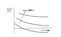
エンジントルク推定部S108では、図6に示したエンジン全性能マップを用いて、エンジン回転速度Neおよびスロットル開度TVO(またはアクセル操作量)から、エンジントルクマップ値tESを検索し、これにエンジンの動特性(吸気系の輸送遅れ分)を時定数TEDの一次遅れとした場合のフィルタを通過させて、エンジントルク推定値tEHを、The engine torque estimation unit S108 searches the engine torque map value tES from the engine rotation speed Ne and the throttle opening TVO (or the accelerator operation amount) using the engine total performance map shown in FIG. The engine torque estimate tEH is passed through a filter when the dynamic characteristic (the transport delay of the intake system) is the first-order delay of the time constant TED ,
目標ロックアップクラッチ締結容量演算部S107では、エンジントルク推定値tEHから目標コンバータトルクtCNVCを減算して目標ロックアップクラッチ締結容量tLUを次式により算出する。The target lockup clutch tightening capacity computing unit S107, the target lockup clutch tightening capacity tLU by subtracting the target converter torque tCNVC from the engine torque estimated value tEH is calculated by the following equation.
ソレノイド駆動信号演算部S110では、実際のロックアップクラッチ締結圧をロックアップクラッチ締結圧指令値(差圧指令値)PLUCにするためのロックアップデューティSDUTYを決定する。The solenoid drive signal calculation unit S110 determines a lockup duty SDUTY for setting the actual lockup clutch engagement pressure to the lockup clutch engagement pressure command value (differential pressure command value)PLUC .
次に、コントローラ5で行われる制御のうち、本発明の要部である、スリップ制御中のフィードフォワード補償器(S101B)の出力急変時におけるフィードバック補償器(S104)の出力補正処理について、図3のフローチャートを用いて説明する。この図3のフローチャートは所定の周期で実行されるものである。 Next, of the control performed by the
ステップS1では、前述の目標スリップ回転演算部(S100)にて設定した目標スリップ回転ωSLPTと、実スリップ回転演算部(S103)にて算出した実スリップ回転ωSLPRとの偏差の絶対値△ωSLPを、
△ωSLP=|ωSLPT−ωSLPR|
として算出する。In step S1, the absolute value Δω of the deviation between the target slip rotation ωSLPT set by the target slip rotation calculation unit (S100) and the actual slip rotation ωSLPR calculated by the actual slip rotation calculation unit (S103).SLP
△ ωSLP = | ωSLPT −ωSLPR |
Calculate as
ステップS2では、この△ωSLPと予め設定されていた所定値DSLP1とを比較し、
△ωSLP>DSLP1
である場合は、設定領域A(図8参照)と判断してステップS3へ進む。そうでない場合は、設定領域B(図8参照)と判断してステップS5へ進む。In step S2, this ΔωSLP is compared with a predetermined value DSLP1 set in advance.
△ ωSLP > DSLP1
If it is, it is determined as the setting area A (see FIG. 8), and the process proceeds to step S3. Otherwise, it is determined as the setting area B (see FIG. 8) and the process proceeds to step S5.
ステップS3では、図8より現在の△ωSLPに応じた規範モデルの時定数Ttを設定する。In step S3, the time constant Tt of the reference model corresponding to the current ΔωSLP is set from FIG.
続くステップS4では、前サイクルの設定領域が同じAだったかどうかを判定し、前回もAだった場合はステップS7へ進み、そうでなかった場合はステップS8へ進む。 In subsequent step S4, it is determined whether or not the setting area of the previous cycle is the same A. If the previous area is also A, the process proceeds to step S7, and if not, the process proceeds to step S8.
ステップS5では、上記と同様に図8を用いて△ωSLPに応じた規範モデルの時定数Ttを設定する。続くステップS6では、前サイクルの設定領域が同じBだったかどうかを判定し、前回もBだった場合はステップS7へ進み、そうでなかった場合はステップS8へ進む。In step S5, the time constant Tt of the reference model corresponding to ΔωSLP is set using FIG. 8 as described above. In the subsequent step S6, it is determined whether or not the set area of the previous cycle is the same B. If the previous area was also B, the process proceeds to step S7, and if not, the process proceeds to step S8.
ステップS7では、設定領域が前サイクル(前回の制御周期)と同一であるため、時定数の変化が起こらず、本発明のポイントであるフィードフォワード補償器(S101B)の変化量によるフォードバック補償器(S104)の出力補正は不要であり、補正要求フラグ(fADJREQ)をクリアする。 In step S7, since the set region is the same as the previous cycle (previous control cycle), the time constant does not change, and the Fordback compensator according to the change amount of the feedforward compensator (S101B), which is the point of the present invention. The output correction in (S104) is unnecessary, and the correction request flag (fADJREQ) is cleared.
一方、ステップS8では、上記ステップS3およびステップS5にて設定した規範モデルの時定数Ttと、制御対象であるスリップ回転モデルの時定数Tpとを比較し、
Tt>Tp
であれば、ステップS9へ進み、フィードバック補償器(S104)の出力補正を行なうために補正要求フラグ(fADJREQ)をセットする。そうでない場合には、ステップS7へ進み、補正要求フラグ(fADJREQ)をクリアし、フィードバック補償器の出力補正を行なわないようにする。On the other hand, in step S8, the time constant Tt of the reference model set in steps S3 and S5 is compared with the time constant Tp of the slip rotation model to be controlled,
Tt> Tp
If so, the process proceeds to step S9, and a correction request flag (fADJREQ) is set to correct the output of the feedback compensator (S104). If not, the process proceeds to step S7, the correction request flag (fADJREQ) is cleared, and the output correction of the feedback compensator is not performed.
以上、ステップS3、S4、S7およびS5、S6、S7における処理は、時定数変化によるフィードフォワード補償器(S101B)の急変が発生しないため、フィードバック補償器(S104)の出力補正処理要求を行なわない。 As described above, the processing in steps S3, S4, S7 and S5, S6, and S7 does not cause a sudden change of the feedforward compensator (S101B) due to a change in time constant, and therefore does not make an output correction processing request for the feedback compensator (S104). .
ステップS3、S4、S8およびS5、S6、S8は同補正処理要求を行なう場合ではあるが、フィードフォワード補償器(S101B)における時定数の大小関係により、補正処理要求を行なうかどうかを判断する。 Steps S3, S4, S8 and S5, S6, S8 are cases where the same correction processing request is made, but it is determined whether or not the correction processing request is to be made based on the magnitude relationship of the time constants in the feedforward compensator (S101B).
続いて、設定した補正要求フラグ(fADJREQ)により、フィードバック補償器(S104)の出力を補正する処理について、図4のフローチャートを用いて説明する。なお、図4のフローチャートは所定の周期で実行されるものである。 Next, processing for correcting the output of the feedback compensator (S104) with the set correction request flag (fADJREQ) will be described with reference to the flowchart of FIG. The flowchart in FIG. 4 is executed at a predetermined cycle.
ステップS50では、前述の前置補償器におけるフォードフォワード補償器(S101B)の出力値ωSLPTC2をメモリバッファ(図示省略)に蓄え、SLPTC2_Mとする。In step S50, the output value ωSLPTC2 of the Ford forward compensator (S101B) in the pre-compensator described above is stored in a memory buffer (not shown) as SLPTC2_M.
ステップS51では、フィードフォワード補償器(S101B)の演算を行ない、今サイクルの出力値ωSLPTC2を算出する。In step S51, the feedforward compensator (S101B) isoperated to calculate the output value ωSLPTC2 of the current cycle.
ステップS52では、フィードバック補償器(S104)の演算を行なう。ただし、後述のステップS56にてフィードバック補償器(S104)の出力値に対して補正処理を行なうことがあるため、フィードバック補償器(S104)の出力の候補値ωSLPC3とする。In step S52, the feedback compensator (S104) is operated. However, since correction processing may be performed on the output value of the feedback compensator (S104) in step S56, which will be described later, the candidate value ωSLPC3 of the output of the feedback compensator (S104) is used.
ステップS53では、図3のフローチャートにて設定した補正要求フラグ(fADJREQ)を参照し、補正要求あり(fADJREQ=1)の場合はステップS54へ、補正要求なし(fADJREQ=0)の場合はステップS55へ進む。 In step S53, the correction request flag (fADJREQ) set in the flowchart of FIG. 3 is referred to, and when there is a correction request (fADJREQ = 1), the process goes to step S54, and when there is no correction request (fADJREQ = 0), step S55. Proceed to
ステップS54ではフィードバック補償器(S104)の出力補正を行なう場合の補正量ωSLPADJを、
ωSLPADJ=ωSLPTC2−SLPTC2_M
として演算し、ステップS56へ進む。In step S54, the correction amount ωSLPADJ for the output correction of the feedback compensator (S104) is
ωSLPADJ = ωSLPTC2 -SLPTC2_M
And the process proceeds to step S56.
ステップS55では同出力補正を行なわない場合であり、補正量ωSLPADJを、
ωSLPADJ=0
として、ステップS56へ進む。In step S55, the same output correction is not performed, and the correction amount ωSLPADJ is set to
ωSLPADJ = 0
Then, the process proceeds to step S56.
ステップS56では、フィードバック補償器(S104)の出力ωSLPC1を、
ωSLPC1=ωSLPC3−ωSLPADJとして算出する。In step S56, the output ωSLPC1 of the feedback compensator (S104) is
Calculated as ωSLPC1 = ωSLPC3 −ωSLPADJ .
以上、ステップS53、S54、S56にて、フィードフォワード補償器(S101B)の出力変化分をフィードバック補償器(S104)の出力を補正することで対応する処理を行ない、ステップS53、S55、S56にて、フィードバック補償器(S104)の出力を補正しない場合の処理を行なう。 As described above, in steps S53, S54, and S56, the corresponding processing is performed by correcting the output change of the feedforward compensator (S101B) by correcting the output of the feedback compensator (S104), and in steps S53, S55, and S56. Then, processing is performed when the output of the feedback compensator (S104) is not corrected.
以上述べた実施例のタイミングチャートを図9に示す。 FIG. 9 shows a timing chart of the embodiment described above.
図9は、設定された目標スリップ回転ωSLPTに向けて実スリップ回転ωSLPRRが収束するように時刻t0からスリップ制御をしている状況である。FIG. 9 shows a situation in which slip control is performed from time t0 so that the actual slip rotation ωSLPRR converges toward the set target slip rotation ωSLPT .
ここで、時刻t1において、実スリップ回転ωSLPRと目標スリップ回転ωSLPTとの偏差が設定値DSLP1以内になると、時定数TtをT1からT2へ切り替える。これにより、フィードフォワード補償器の出力ωSLPTC2がωSLPADJだけステップ状に変化(減少)している。Here, at time t1, when the deviation between the actual slip rotation ωSLPR and the target slip rotation ωSLPT is within the set value DSLP1, the time constant Tt is switched from T1 to T2. As a result, the output ωSLPTC2 of the feedforward compensator changes (decreases)stepwise by ωSLPADJ .
しかしながら、本発明では、同時刻においてフィードバック補償器の出力ωSLPC1を、フィードフォワード補償器の変化量分ωSLPADJだけ逆方向(上昇方向)に補正しているため、フィードフォワードおよびフィードバックの各補償器出力を加算したスリップ回転指令値ωSLPCは同時刻t1においても滑らかに変化している。However, in the present invention, the output omegaSLPC1 of the feedback compensator in the same time, since the correction only backward (upward direction) variation amount omegaSLPADJ of feedforward compensator, the compensator of the feedforward and feedback The slip rotation command value ωSLPC obtained by adding the output changes smoothly at the same time t1.
これにより、スリップ回転指令値を変換した差圧指令値PLUCにおいても滑らかに変化する事になり、締結間際における差圧指令値の急変を抑え、目標応答の変更に柔軟に対応できることになる。Thus, also it becomes possible to change smoothly in the slip rotation command value converted differential pressure command value PLUC to suppress the rapid change of the differential pressure command value at the fastening verge, so that can flexibly respond to changes in target response.
図10は、上記図9と同様に時刻t0からスリップ制御を開始し、時刻t1において目標応答の設定を変えるために目標時定数TtをT1からT2へ切り替えている。しかしながら、時刻t1以降の時定数の大小関係がTp>Ttとなっているため、フィードフォワード補償器が進み補償器として作用している。 In FIG. 10, slip control is started from time t0 as in FIG. 9, and the target time constant Tt is switched from T1 to T2 in order to change the setting of the target response at time t1. However, since the magnitude relationship between the time constants after time t1 is Tp> Tt, the feedforward compensator acts as a lead compensator.
このような状況において、時刻t1におけるフィードフォワード補償器出力ωSLPTC2のステップ状変化は解消できるが、時刻t1からt2におけるフィードフォワード補償器の出力が増加する部分は残ってしまう。これは、スリップ回転指令値ωSLPCとしては時刻t1以降増加することになり、差圧指令値PLUCとしては減少する方向に作用することになる。本来、速やかに目標スリップ回転に収束させることを目的として、時刻t1において時定数を小さく設定したのにもかかわらず、結果として差圧指令値PLUCを減少させていたのでは、かえって実スリップ回転が大きくなってしまうなど、好ましくない状況になってしまう。In such a situation, the step-like change in the feedforward compensator output ωSLPTC2 at time t1 can be eliminated, but a portion where the output of the feedforward compensator increases from time t1 to t2 remains. This increases as the slip rotation command value ωSLPC after time t1, and acts as a decrease in the differential pressure command value PLUC . Originally, for the purpose of quickly converging to the target slip rotation, the differential pressure command value PLUC was reduced as a result, although the time constant was set small at the time t1, the actual slip rotation was instead. It becomes an unfavorable situation such as becoming larger.
そこで、図11のように、時刻t1における時定数変化(Tt)からフィードフォワード補償器の出力変化を読み取り、進み補償的に動作する場合は、フィードバック補償器の出力に対する補正を禁止する。 Therefore, as shown in FIG. 11, when the output change of the feedforward compensator is read from the time constant change (Tt) at time t1, and the operation is advanced compensation, the correction of the output of the feedback compensator is prohibited.
これにより、時刻t1におけるフィードフォワード補償器出力ωSLPTC2のステップ変化は、そのままスリップ回転指令値ωSLPCおよび差圧指令値PLUCの変化として現れてしまうものの、時刻t2における差圧指令値PLUCは時刻t1と比較して増加しており、実スリップ回転ωSLPRを減少させる本来の目的に合致した動作となる。Thus, a step change in feedforward compensator output omegaSLPTC2 at time t1, although thus it appears as a change of the slip rotation command value omegaSLPC and differential pressure command value PLUC, differential pressure command value PLUC at time t2, Compared to the time t1, the operation is in accordance with the original purpose of reducing the actual slip rotation ωSLPR .
以上のように、本発明によれば規範モデルGR(S)が変化することで、フィードフォワード補償器(S101B)の出力ωSLPTC2が急変した場合、フィードバック補償器(S104)の出力ωSLPC1を補正するようにしたので、フィードフォワード補償器の出力が変化したことによるスリップ回転指令値ωSLPCの急変分を、フィードバック補償器(S104)で吸収することができるため、前記従来例において発生していたスリップ回転指令値が急変することによる差圧指令値PLUCの急変を防止できる。これにより、前記従来例の図12で示したような、ロックアップクラッチの急締結を防いで、運転者に違和感を与えるのを防止できるのである。As described above, according to the present invention, when the output ωSLPTC2 of the feedforward compensator (S101B) suddenly changes due to the change of the reference model GR (S), the output ωSLPC1 of the feedback compensator (S104) ischanged . Since the correction was made, the sudden variation of the slip rotation command value ωSLPC due to the change of the output of the feedforward compensator can be absorbed by the feedback compensator (S104), and thus occurs in the conventional example. A sudden change in the differential pressure command value PLUC due to a sudden change in the slip rotation command value can be prevented. This prevents sudden engagement of the lock-up clutch as shown in FIG. 12 of the conventional example, thereby preventing the driver from feeling uncomfortable.
また、規範モデルGR(S)が変化することで、フィードフォワード補償器(S101B)の出力ωSLPTC2が急変した場合、このフィードフォワード補償器の出力変化分に相当する量だけ、フィードバック補償器(S104)の出力ωSLPC1を補正するようにしたので、上述のようなロックアップクラッチの急締結を確実に防ぐことが可能となり、運転性を向上させることができる。In addition, when the output ωSLPTC2 of the feedforward compensator (S101B) changes suddenly due to the change of the reference model GR (S), the feedback compensator ( Since the output ωSLPC1 of S104) is corrected, it is possible to reliably prevent the sudden engagement of the lockup clutch as described above, and to improve drivability.
特に、フィードフォワード補償器の出力が増加した場合は、この増加量に相当する分だけフィードバック補償器の出力を減少させる。逆に、フィードフォワード補償器の出力が減少した場合は、この減少量に相当する分だけ出力を増加させることで、ロックアップクラッチの急締結や締結の遅れを防止することができる。 In particular, when the output of the feedforward compensator increases, the output of the feedback compensator is decreased by an amount corresponding to this increase amount. Conversely, when the output of the feedforward compensator decreases, the output is increased by an amount corresponding to the amount of decrease, thereby preventing sudden engagement of the lockup clutch and engagement delay.
また、フィードバック補償器(S104)の出力補正を実施するかどうかは、フィードフォワード補償器(S101B)におけるフィルタ定数(時定数Tt、Tp)の大小関係によって判断し、この比較結果に応じてフィードバック補償器(S104)の出力補正を行なうかどうかを決定することで、スリップ制御中に差圧指令値PLUCが減少するのを防止して、ロックアップクラッチの締結遅れを確実に防ぐことができる。Whether or not to perform output correction of the feedback compensator (S104) is determined by the magnitude relationship of the filter constants (time constants Tt and Tp) in the feedforward compensator (S101B), and feedback compensation is performed according to the comparison result. By determining whether or not to correct the output of the device (S104), it is possible to prevent the differential pressure command valuePLUC from decreasing during the slip control, and to reliably prevent the lockup clutch from being delayed.
すなわち、フィードフォワード補償器(S101B)が上記(5)式のように構成されている場合、図10のように、制御対象モデルの時定数Tpに対して、目標時定数Ttが小さくなるほど、ロックアップクラッチの締結の遅れが顕著になる。そして、時定数の大小関係がTt<Tpになると、フィードフォワード補償器が進み補償器として作用するが、このような状況においてフィードバック補償器の出力補正を実施すると次のような問題が発生する。 That is, when the feedforward compensator (S101B) is configured as in the above equation (5), as the target time constant Tt becomes smaller than the time constant Tp of the controlled object model as shown in FIG. The delay in fastening the up clutch becomes significant. When the magnitude relationship of the time constants becomes Tt <Tp, the feedforward compensator acts as a lead compensator. However, when the output compensation of the feedback compensator is performed in such a situation, the following problem occurs.
つまり、図10のようにフィードフォワード出力ωSLPTC2のステップ状変化分は補正して消すことができるが、その後の変化部分(図10における時刻t1〜t2、ステップ状の変化から戻る部分)は残ってしまう。このため、図10の場合では、スリップ回転指令値ωSLPCを増加する、つまり差圧指令値PLUCを減少する方向に作用してしまうことになる。本来、図10は目標時定数Ttを小さくし、実スリップ回転を速やかに目標値に対して収束させたい状況であり、差圧を上昇させるべき状況なのであるが、フィードバック補償器の出力補正を行うことで逆の動作をしてしまうことになる。That is, as shown in FIG. 10, the step-like change of the feedforward output ωSLPTC2 can be corrected and erased, but the subsequent change portion (time t1 to t2 in FIG. 10, the portion returning from the step-like change) remains. End up. For this reason, in the case of FIG. 10, the slip rotation command value ωSLPC is increased, that is, the differential pressure command value PLUC is decreased. Originally, FIG. 10 shows a situation in which the target time constant Tt is reduced and the actual slip rotation needs to be quickly converged to the target value, and the differential pressure should be increased. However, the output of the feedback compensator is corrected. This will cause the reverse operation.
このような現象の発生を回避するために、時定数Tt、Tpの大小関係に応じて、フィードバック補償器の出力補正を禁止することで、ロックアップクラッチの締結遅れを回避することができるのである。 In order to avoid the occurrence of such a phenomenon, it is possible to avoid the lock-up clutch engagement delay by prohibiting the output correction of the feedback compensator according to the magnitude relationship between the time constants Tt and Tp. .
なお、本実施形態では、規範モデルを1次遅れ系、フィードフォワード補償器の伝達特性を分子・分母ともに1次の構成として説明したが、各々の伝達特性が高次の場合であっても同様に適用可能である。なぜならば、本発明の狙いは、フィードフォワード補償器の出力変化が、本制御系における最終的な指令値である差圧指令値として好ましくない動きをするときに、フィードバック補償器の出力を補正する点にあり、補償器の次数に限定されるものではないからである。 In the present embodiment, the reference model is described as a first-order lag system, and the transfer characteristics of the feedforward compensator are described as a first-order configuration for both the numerator and the denominator. It is applicable to. This is because the aim of the present invention is to correct the output of the feedback compensator when the change in the output of the feedforward compensator moves unfavorably as the differential pressure command value that is the final command value in this control system. This is because it is not limited to the order of the compensator.
また、本実施形態では、時定数が急変する事をフィードフォワード補償器の出力が急変する要因としたため、設計者が予め設定した時定数自体が急変するタイミングをフィードフォワード補償器の出力が急変するタイミングとして捉え、説明した。しかしながら、例えば、フィードフォワード補償器の出力変化がある所定値を越えたら、本発明を適用するように構成しても、同様の効果が得られる事は明らかである。 Further, in the present embodiment, since the sudden change of the time constant is a factor that causes the output of the feedforward compensator to suddenly change, the output of the feedforward compensator suddenly changes at the timing when the time constant itself preset by the designer changes suddenly. I explained it as timing. However, for example, if the output change of the feedforward compensator exceeds a predetermined value, it is obvious that the same effect can be obtained even if the present invention is applied.
以上のように、本発明に係るトルクコンバータのスリップ制御装置では、運転性に優れた車両の変速機などに適用することができる。 As described above, the slip converter for a torque converter according to the present invention can be applied to a transmission of a vehicle having excellent drivability.
1 トルクコンバータ
2 ロックアップクラッチ
3 ロックアップ制御弁
4 ロックアップソレノイド
5 コントローラ1
Claims (5)
Translated fromJapanese車両の運転状態に基づいて、前記トルクコンバータがコンバータ状態からスリップ状態へ移行する際に、車両の運転状態から前記ロックアップクラッチの目標スリップ回転速度を求める目標スリップ回転算出部と、
前記トルクコンバータのポンプインペラ回転速度とタービン回転速度から実際のスリップ回転速度を検出する実スリップ回転速度検出手段と、
前記目標スリップ回転速度と実際のスリップ回転速度に基づいてフィードバック制御によりロックアップクラッチの締結状態を制御するための出力を算出するフィードバック補償手段と、
前記目標スリップ回転速度に基づいてフィードフォワード制御によりロックアップクラッチの締結状態を制御するための出力を算出するフィードフォワード補償手段と、
前記フィードバック補償手段の指令値とフィードフォワード補償手段の指令値に基づいてロックアップクラッチの締結状態を制御するスリップ制御手段と、を備えたロックアップクラッチのスリップ制御装置において、
前記フィードフォワード補償手段の出力が急激に変化したときには、この出力の変化を吸収するように前記フィードバック補償手段の出力を補正する補正手段を備えたことを特徴とするトルクコンバータのスリップ制御装置。A torque converter provided with a lock-up clutch and interposed between the engine and the automatic transmission;
A target slip rotation calculating unit for obtaining a target slip rotation speed of the lock-up clutch from the driving state of the vehicle when the torque converter shifts from the converter state to the slip state based on the driving state of the vehicle;
An actual slip rotation speed detecting means for detecting an actual slip rotation speed from the pump impeller rotation speed and the turbine rotation speed of the torque converter;
Feedback compensation means for calculating an output for controlling the engagement state of the lockup clutch by feedback control based on the target slip rotation speed and the actual slip rotation speed;
Feedforward compensation means for calculating an output for controlling the engagement state of the lockup clutch by feedforward control based on the target slip rotation speed;
A slip control device for a lockup clutch, comprising: a slip control means for controlling a fastening state of the lockup clutch based on a command value of the feedback compensation means and a command value of the feedforward compensation means;
A slip control apparatus for a torque converter, comprising: correction means for correcting the output of the feedback compensation means so as to absorb the change in output when the output of the feedforward compensation means changes suddenly.
前記補正手段は、前記時定数Tpと時定数Ttの大小関係に基づいて、フィードバック補償手段の出力を補正するか否かを決定することを特徴とする請求項1または請求項2に記載のトルクコンバータのスリップ制御装置。The feedforward compensation means has a time constant Tp of the controlled object model and a time constant Tt of the reference model,
3. The torque according to claim 1, wherein the correction unit determines whether or not to correct the output of the feedback compensation unit based on a magnitude relationship between the time constant Tp and the time constant Tt. Converter slip control device.
4. The torque converter according to claim 3, wherein the correction means determines that the output of the feedforward compensation means has changed suddenly when the time constantTt is switched, and corrects the output of the feedback compensation means. Slip control device.
Priority Applications (5)
| Application Number | Priority Date | Filing Date | Title |
|---|---|---|---|
| JP2003407800AJP3890478B2 (en) | 2003-12-05 | 2003-12-05 | Slip control device for torque converter |
| DE602004013259TDE602004013259T2 (en) | 2003-12-05 | 2004-09-14 | Control for the lockup clutch of a torque converter |
| EP04021819AEP1538371B1 (en) | 2003-12-05 | 2004-09-14 | Lockup control of torque converter |
| US10/953,381US7085640B2 (en) | 2003-12-05 | 2004-09-30 | Lockup control of torque converter |
| CNB2004100879640ACN100362266C (en) | 2003-12-05 | 2004-10-27 | Latching Control of Torque Converter |
Applications Claiming Priority (1)
| Application Number | Priority Date | Filing Date | Title |
|---|---|---|---|
| JP2003407800AJP3890478B2 (en) | 2003-12-05 | 2003-12-05 | Slip control device for torque converter |
Publications (2)
| Publication Number | Publication Date |
|---|---|
| JP2005164012A JP2005164012A (en) | 2005-06-23 |
| JP3890478B2true JP3890478B2 (en) | 2007-03-07 |
Family
ID=34464029
Family Applications (1)
| Application Number | Title | Priority Date | Filing Date |
|---|---|---|---|
| JP2003407800AExpired - LifetimeJP3890478B2 (en) | 2003-12-05 | 2003-12-05 | Slip control device for torque converter |
Country Status (5)
| Country | Link |
|---|---|
| US (1) | US7085640B2 (en) |
| EP (1) | EP1538371B1 (en) |
| JP (1) | JP3890478B2 (en) |
| CN (1) | CN100362266C (en) |
| DE (1) | DE602004013259T2 (en) |
Families Citing this family (16)
| Publication number | Priority date | Publication date | Assignee | Title |
|---|---|---|---|---|
| DE10355097A1 (en)* | 2003-11-24 | 2005-08-04 | Volkswagen Ag | Torque transfer device |
| US8812209B2 (en) | 2006-04-15 | 2014-08-19 | Allison Transmission, Inc. | System and method for detecting lockup clutch on-coming capacity |
| US8401755B2 (en)* | 2008-04-15 | 2013-03-19 | Allison Transmission, Inc. | System and method for detecting lockup clutch on-coming capacity |
| US7530924B2 (en)* | 2006-04-17 | 2009-05-12 | Ford Global Technologies, Llc | Torque converter bypass clutch control |
| US9375313B2 (en)* | 2006-09-08 | 2016-06-28 | The Regents Of The University Of California | Intramyocardial patterning for global cardiac resizing and reshaping |
| JP5266843B2 (en)* | 2008-03-31 | 2013-08-21 | アイシン・エィ・ダブリュ株式会社 | Control device for clutch |
| US8150589B2 (en)* | 2008-04-15 | 2012-04-03 | Allison Transmission, Inc. | System and method for managing accumulator effects during engagement of a lockup clutch in a torque converter |
| JP4924620B2 (en)* | 2009-01-13 | 2012-04-25 | トヨタ自動車株式会社 | Vehicle control apparatus and control method |
| JP6015503B2 (en)* | 2012-10-31 | 2016-10-26 | アイシン・エィ・ダブリュ株式会社 | Start clutch control device and control method |
| JP6137199B2 (en)* | 2013-01-18 | 2017-05-31 | アイシン・エィ・ダブリュ株式会社 | Control device and control method for lock-up clutch |
| WO2016035170A1 (en)* | 2014-09-03 | 2016-03-10 | 日産自動車株式会社 | Lock-up clutch control device for vehicle |
| DE102014222457A1 (en)* | 2014-11-04 | 2016-05-04 | Schaeffler Technologies AG & Co. KG | Method for determining a transmission behavior of a drive train |
| JP6123811B2 (en)* | 2015-01-19 | 2017-05-10 | トヨタ自動車株式会社 | Slip control device for lock-up clutch |
| JP6531627B2 (en)* | 2015-11-12 | 2019-06-19 | トヨタ自動車株式会社 | Lock-up clutch control device |
| US10746291B2 (en)* | 2019-01-17 | 2020-08-18 | Ford Global Technologies, Llc | Engine torque and torque converter bypass clutch slip control during vehicle launch |
| CN110661017B (en)* | 2019-09-30 | 2020-10-30 | 潍柴动力股份有限公司 | Battery water pump control method, battery controller and battery |
Family Cites Families (10)
| Publication number | Priority date | Publication date | Assignee | Title |
|---|---|---|---|---|
| US4957194A (en)* | 1987-09-08 | 1990-09-18 | Mazda Motor Corporation | Torque converter slip control device |
| US5627750A (en)* | 1993-12-29 | 1997-05-06 | Toyota Jidosha Kabushiki Kaisha | Clutch slip control device and method of manufacturing the same, clutch slip control method, and vehicle control device |
| DE19504847B4 (en)* | 1994-02-23 | 2006-04-27 | Luk Gs Verwaltungs Kg | Monitoring method for a torque transmission system of a motor vehicle |
| US5527238A (en)* | 1995-04-10 | 1996-06-18 | Ford Motor Company | Automatic transmission bypass clutch slip control using nonlinear nverse dynamics |
| JP3191631B2 (en)* | 1995-08-09 | 2001-07-23 | トヨタ自動車株式会社 | Slip control device for vehicle direct coupling clutch |
| JP3240979B2 (en) | 1997-11-04 | 2001-12-25 | 日産自動車株式会社 | Slip control device for torque converter |
| JP3642018B2 (en)* | 2000-10-27 | 2005-04-27 | 日産自動車株式会社 | Slip control device for torque converter |
| JP4399989B2 (en)* | 2001-02-07 | 2010-01-20 | トヨタ自動車株式会社 | Vehicle control device |
| JP3912254B2 (en)* | 2002-10-28 | 2007-05-09 | 日産自動車株式会社 | Slip control device for torque converter |
| JP3873899B2 (en)* | 2003-02-13 | 2007-01-31 | 日産自動車株式会社 | Slip control device for torque converter |
- 2003
- 2003-12-05JPJP2003407800Apatent/JP3890478B2/ennot_activeExpired - Lifetime
- 2004
- 2004-09-14EPEP04021819Apatent/EP1538371B1/ennot_activeExpired - Lifetime
- 2004-09-14DEDE602004013259Tpatent/DE602004013259T2/ennot_activeExpired - Lifetime
- 2004-09-30USUS10/953,381patent/US7085640B2/ennot_activeExpired - Lifetime
- 2004-10-27CNCNB2004100879640Apatent/CN100362266C/ennot_activeExpired - Lifetime
Also Published As
| Publication number | Publication date |
|---|---|
| JP2005164012A (en) | 2005-06-23 |
| US20050121277A1 (en) | 2005-06-09 |
| US7085640B2 (en) | 2006-08-01 |
| CN100362266C (en) | 2008-01-16 |
| EP1538371A2 (en) | 2005-06-08 |
| EP1538371A3 (en) | 2005-06-15 |
| CN1624361A (en) | 2005-06-08 |
| EP1538371B1 (en) | 2008-04-23 |
| DE602004013259D1 (en) | 2008-06-05 |
| DE602004013259T2 (en) | 2009-05-07 |
Similar Documents
| Publication | Publication Date | Title |
|---|---|---|
| JP3642018B2 (en) | Slip control device for torque converter | |
| JP3890478B2 (en) | Slip control device for torque converter | |
| JP4092504B2 (en) | Slip control device for torque converter | |
| US7854683B2 (en) | Torque converter clutch control | |
| EP1426661B1 (en) | Torque-converter slip control system | |
| US7967727B2 (en) | Clutch control device | |
| JP3873899B2 (en) | Slip control device for torque converter | |
| JP3912254B2 (en) | Slip control device for torque converter | |
| JP4013725B2 (en) | Torque converter control device | |
| JP2003202075A (en) | Control device for torque converter | |
| JP4613493B2 (en) | Slip control device for torque converter | |
| JP2004324847A (en) | Slip control device for torque converter | |
| JP4082700B2 (en) | Slip control device for torque converter | |
| JP4321415B2 (en) | Slip control device for torque converter | |
| JP4082172B2 (en) | Torque converter control device | |
| JP2006162002A (en) | Slip control device for torque converter | |
| JP4650353B2 (en) | Slip control device for torque converter | |
| JP2002257224A (en) | Slip control device for torque converter | |
| JP3435782B2 (en) | Lockup control device for torque converter | |
| JP2004239277A (en) | Slip control device for torque converter | |
| JP2000145948A (en) | Slip control device for torque converter | |
| JP2004324846A (en) | Slip control device for torque converter |
Legal Events
| Date | Code | Title | Description |
|---|---|---|---|
| A131 | Notification of reasons for refusal | Free format text:JAPANESE INTERMEDIATE CODE: A131 Effective date:20060912 | |
| A521 | Request for written amendment filed | Free format text:JAPANESE INTERMEDIATE CODE: A523 Effective date:20061005 | |
| TRDD | Decision of grant or rejection written | ||
| A01 | Written decision to grant a patent or to grant a registration (utility model) | Free format text:JAPANESE INTERMEDIATE CODE: A01 Effective date:20061107 | |
| A61 | First payment of annual fees (during grant procedure) | Free format text:JAPANESE INTERMEDIATE CODE: A61 Effective date:20061120 | |
| R150 | Certificate of patent or registration of utility model | Free format text:JAPANESE INTERMEDIATE CODE: R150 Ref document number:3890478 Country of ref document:JP Free format text:JAPANESE INTERMEDIATE CODE: R150 | |
| FPAY | Renewal fee payment (event date is renewal date of database) | Free format text:PAYMENT UNTIL: 20101215 Year of fee payment:4 | |
| FPAY | Renewal fee payment (event date is renewal date of database) | Free format text:PAYMENT UNTIL: 20111215 Year of fee payment:5 | |
| FPAY | Renewal fee payment (event date is renewal date of database) | Free format text:PAYMENT UNTIL: 20121215 Year of fee payment:6 | |
| FPAY | Renewal fee payment (event date is renewal date of database) | Free format text:PAYMENT UNTIL: 20121215 Year of fee payment:6 | |
| FPAY | Renewal fee payment (event date is renewal date of database) | Free format text:PAYMENT UNTIL: 20131215 Year of fee payment:7 | |
| EXPY | Cancellation because of completion of term |