JP3889416B2 - Ergonomic pointing device - Google Patents
Ergonomic pointing deviceDownload PDFInfo
- Publication number
- JP3889416B2 JP3889416B2JP2004207745AJP2004207745AJP3889416B2JP 3889416 B2JP3889416 B2JP 3889416B2JP 2004207745 AJP2004207745 AJP 2004207745AJP 2004207745 AJP2004207745 AJP 2004207745AJP 3889416 B2JP3889416 B2JP 3889416B2
- Authority
- JP
- Japan
- Prior art keywords
- wheel
- shaft
- contact
- pointing device
- rotation
- Prior art date
- Legal status (The legal status is an assumption and is not a legal conclusion. Google has not performed a legal analysis and makes no representation as to the accuracy of the status listed.)
- Expired - Fee Related
Links
Images


Classifications
- G—PHYSICS
- G06—COMPUTING OR CALCULATING; COUNTING
- G06F—ELECTRIC DIGITAL DATA PROCESSING
- G06F3/00—Input arrangements for transferring data to be processed into a form capable of being handled by the computer; Output arrangements for transferring data from processing unit to output unit, e.g. interface arrangements
- G06F3/01—Input arrangements or combined input and output arrangements for interaction between user and computer
- G06F3/03—Arrangements for converting the position or the displacement of a member into a coded form
- G06F3/033—Pointing devices displaced or positioned by the user, e.g. mice, trackballs, pens or joysticks; Accessories therefor
- G06F3/0362—Pointing devices displaced or positioned by the user, e.g. mice, trackballs, pens or joysticks; Accessories therefor with detection of 1D translations or rotations of an operating part of the device, e.g. scroll wheels, sliders, knobs, rollers or belts
- H—ELECTRICITY
- H01—ELECTRIC ELEMENTS
- H01H—ELECTRIC SWITCHES; RELAYS; SELECTORS; EMERGENCY PROTECTIVE DEVICES
- H01H25/00—Switches with compound movement of handle or other operating part
- H01H25/008—Operating part movable both angularly and rectilinearly, the rectilinear movement being perpendicular to the axis of angular movement
- G—PHYSICS
- G06—COMPUTING OR CALCULATING; COUNTING
- G06F—ELECTRIC DIGITAL DATA PROCESSING
- G06F3/00—Input arrangements for transferring data to be processed into a form capable of being handled by the computer; Output arrangements for transferring data from processing unit to output unit, e.g. interface arrangements
- G06F3/01—Input arrangements or combined input and output arrangements for interaction between user and computer
- G06F3/03—Arrangements for converting the position or the displacement of a member into a coded form
- G06F3/033—Pointing devices displaced or positioned by the user, e.g. mice, trackballs, pens or joysticks; Accessories therefor
- H—ELECTRICITY
- H01—ELECTRIC ELEMENTS
- H01H—ELECTRIC SWITCHES; RELAYS; SELECTORS; EMERGENCY PROTECTIVE DEVICES
- H01H19/00—Switches operated by an operating part which is rotatable about a longitudinal axis thereof and which is acted upon directly by a solid body external to the switch, e.g. by a hand
- H01H19/005—Electromechanical pulse generators
- H01H2019/006—Electromechanical pulse generators being rotation direction sensitive, e.g. the generated pulse or code depends on the direction of rotation of the operating part
- H—ELECTRICITY
- H01—ELECTRIC ELEMENTS
- H01H—ELECTRIC SWITCHES; RELAYS; SELECTORS; EMERGENCY PROTECTIVE DEVICES
- H01H19/00—Switches operated by an operating part which is rotatable about a longitudinal axis thereof and which is acted upon directly by a solid body external to the switch, e.g. by a hand
- H01H19/02—Details
- H01H19/10—Movable parts; Contacts mounted thereon
- H01H19/14—Operating parts, e.g. turn knob
- H01H2019/146—Roller type actuators
Landscapes
- Engineering & Computer Science (AREA)
- General Engineering & Computer Science (AREA)
- Theoretical Computer Science (AREA)
- Human Computer Interaction (AREA)
- Physics & Mathematics (AREA)
- General Physics & Mathematics (AREA)
- Position Input By Displaying (AREA)
- Rotary Switch, Piano Key Switch, And Lever Switch (AREA)
- Switches With Compound Operations (AREA)
- Telephone Set Structure (AREA)
Abstract
Description
Translated fromJapanese本発明は、ユーザからコマンドを受信して電子装置を制御するための人間工学のポインティングデバイスを対象とする。 The present invention is directed to an ergonomic pointing device for receiving commands from a user and controlling an electronic device.
ハンドヘルドおよびポケットサイズのコンピュータ、タブレットコンピュータ、セルラー電話など、小型の移動装置は、重要な一般のツールになってきている。これらは概して非常に小型で大変便利になり、電池の消耗が比較的少ないが、高性能な適用例で稼動することができるようになった。 Small mobile devices, such as handheld and pocket-sized computers, tablet computers, and cellular phones, have become an important common tool. These are generally very small and very convenient, with relatively low battery consumption, but can now be operated in high performance applications.
こうした移動装置にコマンドを入力するためのポインティングデバイスは、現在、様々な構成で入手可能である。機械式(mechanical)エンコーダホイールは、ユーザインターフェースの一部として様々な移動装置でよく使用される。こうした機械式エンコーダホイールの多くは、装置に搭載された回転可能なホイールまたはローラを備える。ホイールが移動すると、変換器がホイールの動きを検出し、動作の方向および量を示す信号を生成する。信号は、たとえば、移動装置のスクリーン上のカーソルの動きを制御するために使用される。たとえば、この信号を使用して、スクリーン上に表示されたウィンドウを、ウィンドウのスクロールバーを使用してウィンドウをスクロールするのと同様にスクロールすることもできる。 Pointing devices for entering commands into such mobile devices are currently available in various configurations. Mechanical encoder wheels are often used in various mobile devices as part of the user interface. Many of these mechanical encoder wheels include a rotatable wheel or roller mounted on the device. As the wheel moves, the transducer detects wheel movement and generates a signal indicating the direction and amount of motion. The signal is used, for example, to control the movement of the cursor on the screen of the mobile device. For example, this signal can be used to scroll a window displayed on the screen in the same way that a window is scrolled using a window scroll bar.
移動装置のサイズを縮小するには、しばしば、より小さいポインティングデバイスを使用することが必要になる。しかし一般に、入力デバイスを小さくし機構を小さくすると、製造がさらに難しくなり、(磨耗が大きくなることを含む)信頼性の問題が増える。通常、製造が難しくなると、より小型のポインティングデバイスを備えた移動装置の製造コストが高くなる。信頼性の問題は、たとえばスクロール可能なウィンドウがジャンプするように見え、またはホイールが不連続に移動するように見えるなど、ホイールの断続的な機能性をもたらす可能性がある。さらに極端な場合は、ホイール全体が故障し、移動装置が使用不能になり、高コストの取替えまたは修理が必要になる。 To reduce the size of the mobile device, it is often necessary to use a smaller pointing device. However, in general, smaller input devices and smaller mechanisms make manufacturing more difficult and increase reliability issues (including increased wear). Usually, when the manufacture becomes difficult, the manufacturing cost of the mobile device having a smaller pointing device increases. Reliability issues can lead to intermittent functionality of the wheel, for example, the scrollable window appears to jump or the wheel appears to move discontinuously. In more extreme cases, the entire wheel fails, making the mobile device unusable and requiring expensive replacement or repair.
簡単に述べると、本発明は、ユーザからコマンドを受信して電子装置を制御するための人間工学のポインティングデバイスを対象とする。この人間工学のポインティングデバイスは、機械式エンコーダホイールとして構成することができる。このエンコーダホイールは全般的にシャフト、ローラ、およびフレームを備える。シャフトはグラウンドバネ接触部および2つの方向検出バネ接触部を備える。ローラはシャフトの周りに配置されて、シャフトの長手方向軸の周りで自由に回転するようになされている。ローラの内部には、ローラの全回転を通してシャフトのグラウンドバネ接触部と電気的接触状態のままであるように構成される導電面が備えられる。あるいはこの導電面は、また、ローラの全回転中に方向検出バネ接触部との電機的接触と非接触を交互に行って、ローラの回転の方向および速度を決定することができるように構成される。フレームは、シャフトを捕獲(captivate)して、シャフトがZ軸に沿って制限された範囲で自由に移動するが、シャフトの長手方向軸の周りでは回転しないように構成される。 Briefly stated, the present invention is directed to an ergonomic pointing device for receiving commands from a user and controlling an electronic device. This ergonomic pointing device can be configured as a mechanical encoder wheel. The encoder wheel generally comprises a shaft, rollers and a frame. The shaft includes a ground spring contact portion and two direction detection spring contact portions. The roller is disposed about the shaft and is adapted to rotate freely about the longitudinal axis of the shaft. Inside the roller is provided a conductive surface configured to remain in electrical contact with the shaft ground spring contact throughout the rotation of the roller. Alternatively, the conductive surface is also configured so that the direction and speed of rotation of the roller can be determined by alternately performing electrical contact and non-contact with the direction detection spring contact portion during the full rotation of the roller. The The frame is configured to capture the shaft and move freely within a limited range along the Z axis, but not rotate about the longitudinal axis of the shaft.
本発明の一態様によれば、電子装置を制御するためのポインティングデバイスは、ホイール、被捕獲シャフト、およびフレームを備える。ホイールは、このホイールの内面の中に非導電性の領域を設けて、非導電性領域がホイールの回転と共にホイールの回転軸の周りで周回するように構成される。被捕獲シャフトは、ホイール内でホイールの回転軸に沿って配置され、被捕獲シャフトの周りで周回する非導電性領域に応答してホイールの導電性内面との接触および非接触を行うように構成されたスイッチ接触部を備える。フレームは、被捕獲シャフトを捕獲して、被捕獲シャフトがホイールの回転と共に回転するのを阻止するように構成される。 According to one aspect of the invention, a pointing device for controlling an electronic device comprises a wheel, a captured shaft, and a frame. The wheel is configured such that a non-conductive region is provided in the inner surface of the wheel so that the non-conductive region circulates around the rotation axis of the wheel as the wheel rotates. The captured shaft is disposed within the wheel along the axis of rotation of the wheel and is configured to contact and non-contact with the conductive inner surface of the wheel in response to a non-conductive region that circulates around the captured shaft The switch contact portion is provided. The frame is configured to capture the captured shaft and prevent the captured shaft from rotating with the rotation of the wheel.
本発明の他の態様によれば、電子装置は、ホイール、被捕獲シャフト、フレーム、およびプロセッサを備える。ホイールは、ホイールの導電性内面の中に非導電性領域を設けて、非導電性領域がホイールの回転と共にホイールの回転軸の周りを周回するように構成される。被捕獲シャフトは、ホイール内でホイールの回転軸に沿って配置され、被捕獲シャフトの周りで周回する非導電性領域に応答して、ホイールの導電性内面との接触および非接触を行うように構成されたスイッチ接触部を備える。フレームは、被捕獲シャフトを捕獲して、被捕獲シャフトがホイールの回転と共に回転するのを阻止するように構成される。プロセッサは、スイッチ接触部からの電気的信号を受信するように構成される。 According to another aspect of the invention, an electronic device comprises a wheel, a captured shaft, a frame, and a processor. The wheel is configured such that a non-conductive region is provided in the conductive inner surface of the wheel so that the non-conductive region circulates around the rotation axis of the wheel as the wheel rotates. The captured shaft is disposed within the wheel along the axis of rotation of the wheel so as to make contact and non-contact with the conductive inner surface of the wheel in response to a non-conductive region that circulates around the captured shaft. A configured switch contact portion is provided. The frame is configured to capture the captured shaft and prevent the captured shaft from rotating with the rotation of the wheel. The processor is configured to receive an electrical signal from the switch contact.
本発明の図で示した実施形態の以下の詳細な説明、および特許請求の範囲について以下に簡潔に要約した添付の図面を参照すれば、本発明の理解が得られ、本発明による改善点が分かるであろう。 The following detailed description of the illustrated embodiments of the invention and the accompanying drawings, briefly summarized below with regard to the claims, provide an understanding of the invention and provide improvements to it. You will understand.
本発明の例示の実施形態の以下の詳細な説明では、添付の図面を参照するが、この図面は本発明の一部を形成し、本発明を実施することができる特定の例示の実施形態を図で示すものである。当業者が本発明を実施することができるように、こうした実施形態を十分詳細に説明する。理解されるように、本発明の精神および範囲から逸脱することなく、他の実施形態を使用することができ、他の変更を加えることもできる。したがって、以下の詳細な説明は、限定的に捉えられるべきではなく、本発明の範囲は、特許請求の範囲によってのみ定義される。 In the following detailed description of exemplary embodiments of the invention, reference is made to the accompanying drawings, which form a part hereof, and in which are shown by way of illustration specific embodiments in which the invention may be practiced. It is shown in the figure. These embodiments are described in sufficient detail to enable those skilled in the art to practice the invention. As will be realized, other embodiments may be used and other modifications may be made without departing from the spirit and scope of the invention. The following detailed description is, therefore, not to be taken in a limiting sense, and the scope of the present invention is defined only by the claims.
本明細書および特許請求の範囲にわたって、以下の用語は、コンテキストが明らかに他の方法で記載されていない限り、本明細書に明確に関連付けられた意味を持つものである。「ある」、「1つの」、および「その」の意味は複数を指すこともあり、「中」には、「中」および「上」が含まれる。用語「接続された(connected)」は、任意の中間のデバイスを使用しない、接続されるアイテムの間の直接電気的接続を指す。用語「結合された(coupled)」は、接続されるアイテムの間の直接電気的接続、および1つまたは複数の受動的または能動的中間デバイスを介した間接的接続を指す。用語「回路」は、共に結合されて所望の機能を提供する、能動的かつ/または受動的な単一の構成要素または複数の構成要素を指す。用語「信号」は、少なくとも1つの電流、電圧、またはデータ信号を指す。図面を参照すると、図を通して同様の番号は同様の部品(part)を示している。 Throughout the specification and claims, the following terms have the meanings specifically associated with the specification, unless the context is clearly stated otherwise. The meanings of “a”, “one”, and “that” may refer to a plurality, and “medium” includes “middle” and “above”. The term “connected” refers to a direct electrical connection between connected items without using any intermediate device. The term “coupled” refers to a direct electrical connection between connected items and an indirect connection through one or more passive or active intermediate devices. The term “circuit” refers to an active and / or passive single component or multiple components that are coupled together to provide a desired function. The term “signal” refers to at least one current, voltage, or data signal. Referring to the drawings, like numerals indicate like parts throughout the views.
簡単に述べると、本発明は、ユーザからコマンドを受信して電子装置を制御するための人間工学のポインティングデバイスを対象とする。この人間工学のポインティングデバイスは、機械式エンコーダホイールとして構成することができる。このエンコーダホイールは全般的に、シャフト、ローラ、およびフレームを備える。シャフトは、グラウンドバネ接触部および2つの方向検出バネ接触部を備える。ローラは、シャフトの長手方向軸の周りで自由に回転するように、シャフトの周囲に配置されている。ローラの内部は、ローラの全回転を通してシャフトのグラウンドバネ接触部と電気的接触状態のままであるように構成された導電面を含む。この導電面は、また、ローラの全回転中、方向検出バネ接触部との電気的接触と非接触を交互に行って、ローラの回転の方向および速度を決定することができるように構成される。フレームは、シャフトを捕獲して、シャフトがZ軸に沿って限定された距離を自由に移動するが、シャフトの長手方向軸の周りでは回転しないように構成される。 Briefly stated, the present invention is directed to an ergonomic pointing device for receiving commands from a user and controlling an electronic device. This ergonomic pointing device can be configured as a mechanical encoder wheel. The encoder wheel generally comprises a shaft, rollers and a frame. The shaft includes a ground spring contact portion and two direction detection spring contact portions. The rollers are arranged around the shaft so as to rotate freely about the longitudinal axis of the shaft. The interior of the roller includes a conductive surface configured to remain in electrical contact with the shaft ground spring contact throughout the rotation of the roller. The conductive surface is also configured to be able to determine the direction and speed of rotation of the roller by alternating electrical contact and non-contact with the direction detection spring contact during the full rotation of the roller. . The frame is configured to capture the shaft and allow the shaft to move freely a limited distance along the Z axis, but not rotate about the longitudinal axis of the shaft.
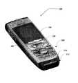
図1は、本発明による例示の移動装置を示す。移動装置100は、図で示したものよりも多い、または少ない構成要素を備えることができる。しかし、図で示した構成要素は、本発明を実施するための例示の実施形態を開示するのに十分である。移動装置100は、ケース102を備える。ケース102は通常、キーパッド104およびディスプレイ106など、ユーザインターフェース手段を支持し保護するように構成される。キーパッド104は、しばしばプログラム可能であり、テキスト入力、ゲーム機能、電話のダイヤル呼び出しなどの機能に使用することができる。ディスプレイ106は、通常、タッチスクリーンインターフェースを任意選択で備えることができ、このインターフェースもテキスト入力に使用することができる。ディスプレイ106を使用して地図、テキスト、ゲーム、ピクチャなどを表示することができる。ユーザは、ホイール108をディスプレイ106と共に使用して、表示された情報を操作し選択することができる。フェーシャ(fascia)110は通常、キーパッド104およびディスプレイ106に重ねられ、フェーシャ110を使用して、ボタン、商標名などのキャプションを表示することができる。ブート112は、ケース102から外側に延びることができ、キーパッド104およびフェーシャ110を取り外して交換するために使用することができる。キーパッド104およびフェーシャ110は、ゲームプレイング、テキスト入力、電話のダイヤル呼び出しなど様々な応用にカスタマイズすることができる。 FIG. 1 shows an exemplary mobile device according to the present invention. The
一般に、移動装置100は、他の移動装置との間で信号を送受信し、着信音など音声信号を提供することができる任意の携帯用コンピューティングデバイスを実質的に備えることができる。こうしたデバイスには、セルラー電話、スマートフォン、音声ページャ、無線周波(RF)デバイス、赤外(IR)デバイス、前記デバイスの1つまたは複数を組み合わせた統合型デバイスなどが含まれる。移動装置100には、音声機能、ハンドヘルドコンピュータ、ウェアラブルコンピュータなどを備えたPersonal Digital Assistants(PDA)など、他のデバイスも含まれる。しかし通常、移動装置100はそれ自体で、機能および特徴に関して広範に及ぶものである。 In general,
図2は、本発明による例示の移動装置の機能的構成要素の実施形態を示す機能ブロック図である。構成要素200は、図で示したものよりも多い、または少ない構成要素を備えることができる。しかし、図で示した構成要素は、本発明を実施するための例示の実施形態を開示するのに十分である。 FIG. 2 is a functional block diagram illustrating an embodiment of functional components of an exemplary mobile device according to the present invention. The
図で示したように、構成要素200は、プロセッサ260、メモリ262、ディスプレイ106、およびキーパッド104を含む。通常、メモリ262には、揮発性メモリ(たとえばRAM)、および不揮発性メモリ(たとえばROM、Flash Memoryなど)が含まれる。構成要素200は、メモリ262に常駐し、プロセッサ260で実行されるMicrosoft CorporationからのWindows(登録商標) CEオペレーティングシステム、または他のこうしたオペレーティングシステムなど、オペレーティングシステム264を含むことができる。キーパッド104は、(通常の電話のような)押しボタン式数字ダイヤルパッド、またはゲームパッドなどでもよい。ディスプレイ106は、液晶ディスプレイ、または移動通信デバイスで通常使用される他のタイプのディスプレイでもよい。たとえば、ディスプレイ106は、タッチセンスでもよく、入力デバイスとしても動作する。 As shown, the
1つまたは複数のアプリケーションプログラム266をメモリ262にロードして、オペレーティングシステム264で実行することができる。アプリケーションプログラムの例には、電話ダイヤルプログラム、電子メールプログラム、ユーザ着信音選択プログラムなどが含まれる。アプリケーションプログラムは、ホイール108に関連して動作し、たとえば、ユーザがリストに表示された特定のデータフィールドを選択することができるようにする。構成要素200は、メモリ262内に不揮発性記憶装置268も含む。不揮発性記憶装置268を使用して、移動装置100がパワーダウンした場合に消滅してはいけない永続情報を格納することができる。アプリケーションプログラム266は、電子メール、ユーザが選択可能な着信音など、記憶装置268の情報を使用し、それに格納することができる。 One or
構成要素200は、1つまたは複数の電池として実装することができる電源270も含む。電源270は、さらにACアダプタ、または電池を補充または再充電する電動格納台(powered docking cradle)など外部の電源を含むこともできる。 The
構成要素200は、2つのタイプの外部通知機構、LED240およびオーディオインターフェース274を備えたものが図で示されている。こうしたデバイスを電源270に直接結合して、それらを起動した場合に、プロセッサ260および他の構成要素が電池の電力を保護するために停止されても、通知機構によって指示された期間中はオン状態のままであるようにする。LED240は、ユーザがデバイスの電源を入れた状態になるよう指示する行動をとるまで、無期限にオン状態のままであるようにプログラミングすることができる。オーディオインターフェース274は、可聴信号をユーザに提供し、可聴信号をユーザから受信するために使用される。たとえば、オーディオインターフェース274をスピーカに結合して可聴出力を提供することができる。ボタンを押し、またはホイール108を操作するなど、入力コマンドに応答して可聴出力を提供することができる。オーディオインターフェース274をマイクロフォン、受信スピーカなどに結合して、可聴入力を受信して、電話の会話を容易にすることなどもできる。
構成要素200は、電波通信を送受信する機能を実行する無線部(ラジオ)272を含むこともできる。無線部272をアンテナに結合することができる。無線部272は、通信業者またはサービス提供者を介して、構成要素200と外界の間の無線接続を容易にする。無線部272へ、またそれからの伝送は、オペレーティングシステム264の制御下で行われ、無線部272によって受信された通信をオペレーティングシステム264を介してアプリケーションプログラム266に、かつその逆に配布することができる。 The
無線部272は、構成要素200がネットワークなどを介して他のコンピューティングデバイスと通信することができるようにする。無線部272は、通信媒体の一例である。通信媒体は通常、コンピュータ可読命令、データ構造、プログラムモジュール、または、搬送波あるいは他の搬送機構など、被変調データ信号の他のデータによって実施することができ、任意の情報配信媒体を含む。用語「被変調データ信号」は、その特性のセットの1つまたは複数を有する信号、または情報を信号に符号化するように変更された信号を指す。例であって限定するものではないが、通信媒体には、有線ネットワークあるいは直接配線接続など有線媒体、および音響、RF、赤外線、および他の無線媒体など無線媒体が含まれる。本明細書で使用する用語、コンピュータ可読媒体には、記憶媒体および通信媒体の両方が含まれる。 The
図3は、本発明によるホイールアセンブリの構成要素を全般的に示す拡大図である。図で示したように、ホイールアセンブリ300には、フレーム310、シャフト320、およびローラ330がある。 FIG. 3 is an enlarged view generally showing components of a wheel assembly according to the present invention. As shown, the
シャフト320は、シャフトベース322、方向検出バネ接触部324、およびグラウンドバネ接触部326を備える。シャフト320は、任意選択のシャフトカバー328も備える。シャフトカバー328は通常、接触部324および326などシャフトの構成要素の固定を助けるために設けられる。シャフト320は、ローラ330がシャフト320の長手方向軸の周囲で前後方向に回転することができるように構成される。 The
フレーム310は、シャフト320(その周囲にローラ330が配置される)を捕獲して、シャフト320が、ローラ330の回転軸に対して実質的に垂直の方向で(たとえばZ軸に沿って上下に)短距離を自由に移動するように構成される。シャフト320も通常、シャフト320がローラ330と共に回転するのが阻止されるように捕獲される。フレーム310は、方向検出バネ接触部324およびグラウンドバネ接触部326に電気的接続を提供する電気的接触部312も備える。 The
方向検出バネ接触部324は、シャフト320内で、接触部(324)が、ローラ330の全回転中、ローラ330との電気的接触と非接触を交互に行うように構成される。方向検出バネ接触部324は通常、回転軸に沿って長さ方向に位置合せされる。 The direction detection
グラウンドバネ接触部326は、シャフト320内で、接触部326がローラ330の全回転を通してローラ330に電気的に結合されたままであるように構成される。方向検出バネ接触部324およびグラウンドバネ接触部326は、ローラ330の回転速度および回転方向を示すためのスイッチとして構成される。他の実施形態では、グラウンドバネ接触部326は、ローラ330の回転速度および回転方向を決定することができる限り、ローラ330の回転に応答して接触および非接触を行うようにも構成することができる。
一実施形態では、ローラ330は、導電性接触スリーブ332およびローラケーシング334を備える。接触スリーブ332は、ローラケーシング334内で堅く固定されて、接触スリーブ332およびホイールケーシング334がユニットとして回転する(かつ回転軸に対して実質的に垂直方向に移動する)ようになされている。内部きざみ付部(inner knurls)338を使用してスリーブ332およびケーシング334をユニットとして堅く固定することができる。接触スリーブ332は任意選択で、回転軸の周りに移動止め位置を提供するように構成されたきざみ付部338を含む。内部きざみ付部338は、グラウンドバネ接触部340と共に動作して、移動止め位置を提供する。 In one embodiment, the
接触スリーブ332は、1つまたは複数の非導電性領域339を備える。非導電性領域339は通常は接触スリーブ332内の開口部として実施されるが、接触スリーブ332内の被覆または凹部を用いることもできる。領域339および接触部324は、開閉部を提供して、電気回路によってローラ330の回転の方向および速度を決定することができるように構成される。領域339および/または接触部324は通常、180°以外の角度で回転軸の周囲に配置されて、電気回路によってローラ330の回転方向を検出することができるように構成される。
他の実施形態では、ローラ330は、ローラ330の回転中に少なくとも1つの回路で開閉するように構成された1つまたは複数の非導電性領域を有する統合型ユニットとして形成することができる。様々な実施形態で、ローラ330は外部きざみ付部336を備えることができ、この外部きざみ付部336は通常、ユーザがローラをより操縦し易くする助けをする。 In other embodiments, the
図4aは、本発明による、部分的に組み立てられたシャフトの構成要素を全般的に示す図である。シャフトベース322は、フレーム310に対向する端部にある垂直の溝内に挿入され、その溝によって捕獲される。方向検出バネ接触部324およびグラウンドバネ接触部326は、シャフトベース322に固定されたところが図で示されている。 FIG. 4a is a diagram generally illustrating the components of a partially assembled shaft according to the present invention. The
図4bは、本発明による、フレームによって捕獲されたシャフトを全般的に示す図である。シャフトカバー328は、シャフトベース322上に取り付けられたところが示されている。方向検出バネ接触部324およびグラウンドバネ接触部326は、シャフトベース322およびシャフトカバー328の外径を越えて部分的に拡張しているところが示されている。フレーム310は、シャフト320を捕獲して、シャフト320が上下方向に短距離を自由に移動するように構成された保持係止クリップ414を有して示されている。係止クリップ414をシャフトベース322およびシャフトカバー328から概ね外側の方向に曲げることによって、シャフトを挿入し、または取り外すことができるようになる。 FIG. 4b is a general illustration of a shaft captured by a frame according to the present invention.
図4cは、本発明による、シャフトの周囲に配置されたシャフトスリーブを全般的に示す図である。シャフト320の一部がシャフトスリーブ332の領域339内に見える。シャフトスリーブ332が、シャフト320の周りで回転するとき、領域339内の空隙の軌道経路に接触部324の接触部分の位置が含まれるため、方向検出接触部324は導電性シャフトスリーブ(332)との接触と非接触を交互に行う。 FIG. 4c is a diagram generally illustrating a shaft sleeve disposed about a shaft according to the present invention. A portion of the
図4dは、本発明による完全に組み立てたホイールアセンブリを全般的に示す図である。ホイールカバー334は、スリーブカバー332の周りに配置される。フレーム310は、プリント回路板などの基板(substrate)上にアセンブリ(300)を搭載するための、ホイールアセンブリ300の位置合せに適切したタブ416を備える。タブ416は、また、(取付後の)取付基板の表面に対して平行に向けられた力に対する張力緩和(strain relief)を提供する。 FIG. 4d is a diagram generally illustrating a fully assembled wheel assembly according to the present invention. The
図5は、本発明による、完全に組み立てたホイールおよび取付基板を示す図である。取付基板510は、ホイールアセンブリ300の下で、その反対側の端部に配置されたスイッチ520を備える。ホイールアセンブリ300を基板510上に取り付けて、ホイール300上に加えられる下向きの力が少なくとも1つのスイッチを動作させるようにすることができる。 FIG. 5 shows a fully assembled wheel and mounting board according to the present invention. The mounting
上記で論じたように、シャフト320をフレーム310によって捕獲して、シャフト320の端部が上下方向に(すなわちZ軸に沿って)独立して比較的自由に移動するようにする。中央領域に伝達される下向きの力は、両スイッチ520を閉じる。長手方向軸の上方に伝達されるが、中央領域の左右にオフセットされる下向きの力は、ホイール300に対して伝達された力の位置に近接している単一のスイッチ520を閉じる。 As discussed above, the
バネ(図示せず)を使用して、押し下げたホイールを元の位置に戻すことができる。バネを、スイッチ520内に配置し、基板510上、ホイールアセンブリ300内、または任意の適した位置に取り付けることができる。バネを(たとえばグラウンドバネ接触部326内または電気的接触部312など)電気的接触部として使用して、たとえば少なくとも1つの方向検出接触部324と電気的に結合することもできる。 A spring (not shown) can be used to return the depressed wheel to its original position. A spring can be placed in the
本発明の他の実施形態も、本発明の精神および範囲から逸脱することなく可能である。たとえば、ホイールを「マウス」内に取り付けて、外部ケーブルを介してプロセッサに電気的に結合することができる。上記の明細書、例、およびデータは、本発明の構成の製造および使用の完全な説明を提供するものである。本発明の精神および範囲から逸脱することなく、本発明の多くの実施形態を作成することができ、本発明は特許請求の範囲内にある。 Other embodiments of the invention are possible without departing from the spirit and scope of the invention. For example, a wheel can be mounted in the “mouse” and electrically coupled to the processor via an external cable. The above specification, examples and data provide a complete description of the manufacture and use of the composition of the invention. Many embodiments of the invention can be made without departing from the spirit and scope of the invention, which is within the scope of the claims.
104 キーパッド
106 ディスプレイ
240 LED
260 プロセッサ
262 メモリ
266 アプリケーションプログラム(群)
268 記憶装置
270 電源
272 無線部
274 オーディオインターフェース
104
260
268
Claims (24)
Translated fromJapanese導電性内面の中に非導電性領域を設けたホイールであって、前記非導電性領域が前記ホイールの回転と共に前記ホイールの回転軸の周りを周回するように構成されたホイールと、
前記ホイール内で前記ホイールの前記回転軸に沿って配置され、前記非導電性領域が被捕獲シャフトの周りを周回するのに応答して、前記ホイールの導電性内面との接触および非接触を行うように構成されたスイッチ接触部を備える被捕獲シャフトと、
前記被捕獲シャフトを捕獲して、前記被捕獲シャフトが前記ホイールの回転と共に回転するのを阻止するように構成されたフレームとを備えることを特徴とするポインティングデバイス。A pointing device for controlling an electronic device,
A wheel provided with a non-conductive region in a conductive inner surface, wherein the non-conductive region is configured to circulate around a rotation axis of the wheel together with the rotation of the wheel;
Located within the wheel along the axis of rotation of the wheel and in contact and non-contact with the conductive inner surface of the wheel in response to the non-conductive region orbiting around the captured shaft A captured shaft comprising a switch contact configured to be
A pointing device comprising: a frame configured to capture the captured shaft and to prevent the captured shaft from rotating with the rotation of the wheel.
導電性内面の中に非導電性領域を設けたホイール手段であって、前記非導電性領域が前記ホイール手段の回転と共に前記ホイール手段の回転軸の周りを周回するように構成されたホイール手段と、
前記ホイール手段内で前記ホイール手段の前記回転軸に沿って配置され、前記非導電性領域がシャフト手段の周りを周回するのに応答して前記ホイールの前記導電性内面との接触および非接触を行うように構成されたスイッチ接触手段を備えるシャフト手段と、
前記シャフト手段を捕獲して、前記シャフト手段が前記ホイール手段の回転と共に回転するのを阻止するように構成されたフレーム手段と
を備えることを特徴とするポインティングデバイス。A pointing device for controlling an electronic device,
Wheel means provided with a non-conductive region in a conductive inner surface, wherein the non-conductive region is configured to circulate around a rotation axis of the wheel means together with the rotation of the wheel means; ,
Arranged in the wheel means along the axis of rotation of the wheel means, in contact and non-contact with the conductive inner surface of the wheel in response to the non-conductive region orbiting around the shaft means. Shaft means comprising switch contact means configured to perform;
A pointing device comprising: frame means configured to capture the shaft means and prevent the shaft means from rotating with rotation of the wheel means.
前記ホイール内で前記ホイールの回転軸に沿って配置され、前記非導電性領域が前記被捕獲シャフトの周りを周回するのに応答して前記ホイールの前記導電性内面との接触および非接触を行うように構成されたスイッチ接触部を備える被捕獲シャフトと、
前記被捕獲シャフトを捕獲して、前記被捕獲シャフトが前記ホイールの回転と共に回転するのを阻止するように構成されたフレームと、
前記スイッチ接触部から電気的信号を受信するように構成されたプロセッサと
を備えることを特徴とする電子装置。A wheel provided with a non-conductive region in a conductive inner surface, wherein the non-conductive region is configured to circulate around a rotation axis of the wheel together with the rotation of the wheel;
Positioned within the wheel along the axis of rotation of the wheel and in contact with and non-contact with the conductive inner surface of the wheel in response to the non-conductive region orbiting around the captured shaft A captured shaft comprising a switch contact configured to be
A frame configured to capture the captured shaft and prevent the captured shaft from rotating with rotation of the wheel;
An electronic device comprising: a processor configured to receive an electrical signal from the switch contact.
Applications Claiming Priority (1)
| Application Number | Priority Date | Filing Date | Title |
|---|---|---|---|
| US10/620,239US7088348B2 (en) | 2003-07-14 | 2003-07-14 | Ergonomic pointing device |
Publications (3)
| Publication Number | Publication Date |
|---|---|
| JP2005038429A JP2005038429A (en) | 2005-02-10 |
| JP2005038429A5 JP2005038429A5 (en) | 2006-10-26 |
| JP3889416B2true JP3889416B2 (en) | 2007-03-07 |
Family
ID=33477091
Family Applications (1)
| Application Number | Title | Priority Date | Filing Date |
|---|---|---|---|
| JP2004207745AExpired - Fee RelatedJP3889416B2 (en) | 2003-07-14 | 2004-07-14 | Ergonomic pointing device |
Country Status (6)
| Country | Link |
|---|---|
| US (1) | US7088348B2 (en) |
| EP (1) | EP1498924B1 (en) |
| JP (1) | JP3889416B2 (en) |
| KR (1) | KR100875312B1 (en) |
| CN (1) | CN100386714C (en) |
| AT (1) | ATE526674T1 (en) |
Families Citing this family (5)
| Publication number | Priority date | Publication date | Assignee | Title |
|---|---|---|---|---|
| JP2005123119A (en)* | 2003-10-20 | 2005-05-12 | Omron Corp | Rotating/pressing operation type electronic component, and electronic apparatus using it |
| JP4363155B2 (en)* | 2003-10-20 | 2009-11-11 | オムロン株式会社 | Rotating / pressing operation type electronic component and electronic device using the same |
| DE102005045007B4 (en)* | 2005-09-21 | 2022-03-24 | Volkswagen Aktiengesellschaft | Operating element, in particular for a vehicle seat in a motor vehicle |
| US7996050B2 (en) | 2006-02-28 | 2011-08-09 | Lg Electronics Inc. | Input device for an electronic device and electronic device having the same |
| US7860538B2 (en)* | 2006-02-28 | 2010-12-28 | Lg Electronics Inc. | Mobile terminal |
Family Cites Families (28)
| Publication number | Priority date | Publication date | Assignee | Title |
|---|---|---|---|---|
| US5019831A (en)* | 1985-05-20 | 1991-05-28 | Texas Instruments Incorporated | Dual end resonant slot array antenna feed having a septum |
| JPH0341341U (en)* | 1989-08-31 | 1991-04-19 | ||
| US5557440A (en) | 1994-01-05 | 1996-09-17 | Microsoft Corporation | Noise-insensitive optoencoding techniques with compensation for device variations |
| US5473344A (en) | 1994-01-06 | 1995-12-05 | Microsoft Corporation | 3-D cursor positioning device |
| US6097371A (en) | 1996-01-02 | 2000-08-01 | Microsoft Corporation | System and method of adjusting display characteristics of a displayable data file using an ergonomic computer input device |
| US5912661A (en) | 1997-01-14 | 1999-06-15 | Microsoft Corp. | Z-encoder mechanism |
| US6031518A (en) | 1997-05-30 | 2000-02-29 | Microsoft Corporation | Ergonomic input device |
| US6097964A (en)* | 1997-09-04 | 2000-08-01 | Nokia Mobile Phones Limited | Navigation key for a handset |
| TW461547U (en)* | 1998-01-20 | 2001-10-21 | Primax Electronics Ltd | Mouse encoding apparatus |
| US6188393B1 (en)* | 1998-10-05 | 2001-02-13 | Sysgration Ltd. | Scroll bar input device for mouse |
| FI106904B (en)* | 1998-12-08 | 2001-04-30 | Nokia Mobile Phones Ltd | Wireless communication means and control means |
| JP2000231448A (en)* | 1999-02-08 | 2000-08-22 | Alps Electric Co Ltd | Mouse with wheel |
| US6246392B1 (en)* | 1999-02-11 | 2001-06-12 | William Wu | Third-axis input device for mouse |
| US6285355B1 (en)* | 1999-05-26 | 2001-09-04 | Key Mouse Electronic Enterprise Co. | Mouse-associated Z-axis encoder |
| US6930259B1 (en)* | 1999-06-10 | 2005-08-16 | Sonion A/S | Encoder |
| US6411279B1 (en)* | 1999-06-16 | 2002-06-25 | Behavior Tech Computer Corp. | Cableless mouse power saving device |
| CN2437087Y (en)* | 1999-09-20 | 2001-06-27 | 赵新宇 | One-key dialing type mobile telephone set |
| JP3952642B2 (en)* | 1999-09-20 | 2007-08-01 | 松下電器産業株式会社 | Press / rotate electronic components |
| US6380927B1 (en) | 1999-11-17 | 2002-04-30 | Microsoft Corporation | Determining the position of a detented optical encoder |
| US6353429B1 (en) | 1999-11-30 | 2002-03-05 | Microsoft Corporation | Detented optical encoder |
| GB2357634B (en)* | 1999-12-21 | 2003-07-16 | Nokia Mobile Phones Ltd | A switch |
| ATE253770T1 (en)* | 2000-01-14 | 2003-11-15 | Sonion As | 3D ROLLING KEY |
| US6340966B1 (en)* | 2000-01-27 | 2002-01-22 | Ching-Shun Wang | Clamping device for third-axis input device of mouse |
| US6556150B1 (en) | 2000-03-24 | 2003-04-29 | Microsoft Corporation | Ergonomic computer input device |
| SE0002698D0 (en) | 2000-07-14 | 2000-07-14 | Rolf Stroemberg | Pointing device with loop and rotatable rods |
| JP4356911B2 (en)* | 2000-11-07 | 2009-11-04 | パナソニック株式会社 | Switch device |
| JP2003008693A (en)* | 2001-06-21 | 2003-01-10 | Nec Access Technica Ltd | Portable telephone |
| CN2531446Y (en)* | 2002-03-18 | 2003-01-15 | 新巨企业股份有限公司 | Modular roller device |
- 2003
- 2003-07-14USUS10/620,239patent/US7088348B2/ennot_activeExpired - Fee Related
- 2004
- 2004-06-30EPEP04015331Apatent/EP1498924B1/ennot_activeExpired - Lifetime
- 2004-06-30ATAT04015331Tpatent/ATE526674T1/ennot_activeIP Right Cessation
- 2004-07-13KRKR1020040054341Apatent/KR100875312B1/ennot_activeExpired - Fee Related
- 2004-07-13CNCNB2004100696654Apatent/CN100386714C/ennot_activeExpired - Fee Related
- 2004-07-14JPJP2004207745Apatent/JP3889416B2/ennot_activeExpired - Fee Related
Also Published As
| Publication number | Publication date |
|---|---|
| KR100875312B1 (en) | 2008-12-19 |
| EP1498924B1 (en) | 2011-09-28 |
| US20050012713A1 (en) | 2005-01-20 |
| JP2005038429A (en) | 2005-02-10 |
| CN1577233A (en) | 2005-02-09 |
| CN100386714C (en) | 2008-05-07 |
| EP1498924A3 (en) | 2007-03-07 |
| EP1498924A2 (en) | 2005-01-19 |
| KR20050010501A (en) | 2005-01-27 |
| ATE526674T1 (en) | 2011-10-15 |
| US7088348B2 (en) | 2006-08-08 |
Similar Documents
| Publication | Publication Date | Title |
|---|---|---|
| US8170633B2 (en) | Mobile terminal configured to be mounted on a user's wrist or forearm | |
| KR100754674B1 (en) | Method and device for selecting menu in mobile terminal | |
| EP2722738B1 (en) | Mobile terminal | |
| JP4988122B2 (en) | Wireless portable electronic communication device comprising multiple elements for automatic setting and method for automatically setting operation mode of the device | |
| US6968508B2 (en) | Rotating user interface | |
| US20090156255A1 (en) | Mobile terminal | |
| US8195252B2 (en) | Input device for mobile terminal using scroll key | |
| US7825914B2 (en) | Trigger operated portable electronic device | |
| JP2001236859A (en) | Rotary switch | |
| US20050124387A1 (en) | Portable apparatus user interface | |
| US7705838B2 (en) | Movable user interface | |
| CN111984063A (en) | Telescopic structure, method and terminal for telescopic screen | |
| US20060192764A1 (en) | Navigation wheel having switching assembly | |
| JP3889416B2 (en) | Ergonomic pointing device | |
| US20070123320A1 (en) | Key input device for portable terminal | |
| JP5489213B2 (en) | Electronic device and program | |
| JP4209917B2 (en) | Keypad for terminals that can be pulled out | |
| US7535464B1 (en) | Navigation wheel having discrete switches | |
| JP4347117B2 (en) | Operating device and electronic device | |
| US7529572B2 (en) | Mobile electric device | |
| EP1978439A1 (en) | Trigger operated portable electronic device | |
| JP2001016312A (en) | Mobile communication terminal |
Legal Events
| Date | Code | Title | Description |
|---|---|---|---|
| RD03 | Notification of appointment of power of attorney | Free format text:JAPANESE INTERMEDIATE CODE: A7423 Effective date:20060811 | |
| A521 | Request for written amendment filed | Free format text:JAPANESE INTERMEDIATE CODE: A523 Effective date:20060824 | |
| A621 | Written request for application examination | Free format text:JAPANESE INTERMEDIATE CODE: A621 Effective date:20060824 | |
| A871 | Explanation of circumstances concerning accelerated examination | Free format text:JAPANESE INTERMEDIATE CODE: A871 Effective date:20060825 | |
| RD04 | Notification of resignation of power of attorney | Free format text:JAPANESE INTERMEDIATE CODE: A7424 Effective date:20060905 | |
| A521 | Request for written amendment filed | Free format text:JAPANESE INTERMEDIATE CODE: A821 Effective date:20060811 | |
| A975 | Report on accelerated examination | Free format text:JAPANESE INTERMEDIATE CODE: A971005 Effective date:20061011 | |
| TRDD | Decision of grant or rejection written | ||
| A01 | Written decision to grant a patent or to grant a registration (utility model) | Free format text:JAPANESE INTERMEDIATE CODE: A01 Effective date:20061031 | |
| A61 | First payment of annual fees (during grant procedure) | Free format text:JAPANESE INTERMEDIATE CODE: A61 Effective date:20061129 | |
| R150 | Certificate of patent or registration of utility model | Free format text:JAPANESE INTERMEDIATE CODE: R150 | |
| FPAY | Renewal fee payment (event date is renewal date of database) | Free format text:PAYMENT UNTIL: 20101208 Year of fee payment:4 | |
| FPAY | Renewal fee payment (event date is renewal date of database) | Free format text:PAYMENT UNTIL: 20101208 Year of fee payment:4 | |
| FPAY | Renewal fee payment (event date is renewal date of database) | Free format text:PAYMENT UNTIL: 20111208 Year of fee payment:5 | |
| FPAY | Renewal fee payment (event date is renewal date of database) | Free format text:PAYMENT UNTIL: 20111208 Year of fee payment:5 | |
| FPAY | Renewal fee payment (event date is renewal date of database) | Free format text:PAYMENT UNTIL: 20121208 Year of fee payment:6 | |
| FPAY | Renewal fee payment (event date is renewal date of database) | Free format text:PAYMENT UNTIL: 20121208 Year of fee payment:6 | |
| FPAY | Renewal fee payment (event date is renewal date of database) | Free format text:PAYMENT UNTIL: 20131208 Year of fee payment:7 | |
| R250 | Receipt of annual fees | Free format text:JAPANESE INTERMEDIATE CODE: R250 | |
| R250 | Receipt of annual fees | Free format text:JAPANESE INTERMEDIATE CODE: R250 | |
| S111 | Request for change of ownership or part of ownership | Free format text:JAPANESE INTERMEDIATE CODE: R313113 | |
| R350 | Written notification of registration of transfer | Free format text:JAPANESE INTERMEDIATE CODE: R350 | |
| LAPS | Cancellation because of no payment of annual fees |