JP3889265B2 - Cushion device - Google Patents
Cushion deviceDownload PDFInfo
- Publication number
- JP3889265B2 JP3889265B2JP2001327883AJP2001327883AJP3889265B2JP 3889265 B2JP3889265 B2JP 3889265B2JP 2001327883 AJP2001327883 AJP 2001327883AJP 2001327883 AJP2001327883 AJP 2001327883AJP 3889265 B2JP3889265 B2JP 3889265B2
- Authority
- JP
- Japan
- Prior art keywords
- elastic layer
- partition wall
- cushion
- cushion core
- peripheral surface
- Prior art date
- Legal status (The legal status is an assumption and is not a legal conclusion. Google has not performed a legal analysis and makes no representation as to the accuracy of the status listed.)
- Expired - Fee Related
Links
Images


Classifications
- A—HUMAN NECESSITIES
- A47—FURNITURE; DOMESTIC ARTICLES OR APPLIANCES; COFFEE MILLS; SPICE MILLS; SUCTION CLEANERS IN GENERAL
- A47C—CHAIRS; SOFAS; BEDS
- A47C27/00—Spring, stuffed or fluid mattresses or cushions specially adapted for chairs, beds or sofas
- A47C27/14—Spring, stuffed or fluid mattresses or cushions specially adapted for chairs, beds or sofas with foamed material inlays
- A47C27/148—Spring, stuffed or fluid mattresses or cushions specially adapted for chairs, beds or sofas with foamed material inlays of different resilience
- A—HUMAN NECESSITIES
- A47—FURNITURE; DOMESTIC ARTICLES OR APPLIANCES; COFFEE MILLS; SPICE MILLS; SUCTION CLEANERS IN GENERAL
- A47C—CHAIRS; SOFAS; BEDS
- A47C27/00—Spring, stuffed or fluid mattresses or cushions specially adapted for chairs, beds or sofas
- A47C27/14—Spring, stuffed or fluid mattresses or cushions specially adapted for chairs, beds or sofas with foamed material inlays
- A47C27/15—Spring, stuffed or fluid mattresses or cushions specially adapted for chairs, beds or sofas with foamed material inlays consisting of two or more layers
Landscapes
- Mattresses And Other Support Structures For Chairs And Beds (AREA)
- Laminated Bodies (AREA)
Description
Translated fromJapanese【0001】
【発明の属する技術分野】
この発明はベッド用のマットレス、ソファー、椅子、車両用シートなどに使用されるクッション装置に関する。
【0002】
【従来の技術】
たとえばクッション装置である、ベッド用のマットレスにおいては、快適な寝心地を損なうことなく人体を弾性的に支持する機能、すなわち良好なクッション性能が要求される。
【0003】
上記マットレスはクッション体を有し、このクッション体の上下面にシート状の弾性材を積層し、この積層体を外装地によって被覆して構成されている。上記クッション体としてはスプリングユニットが用いられることが多い。スプリングユニットは、多数のコイルスプリングをヘリカル線によって行列状に連結して形成されている。
【0004】
クッション体をコイルスプリングによって形成したマットレスの場合、コイルスプリングは利用者の荷重を受けて圧縮変形すると、その変形量に応じて反発力を生じるから、その反発力によってマットレス上に仰臥した利用者は身体が圧迫され、快適な寝心地が損なわれるということがある。
【0005】
上記クッション体をコイルスプリングに代わり、ゲル化材料によって形成することが提案されている。ゲル化材料によって形成されたクッション体は、高い熱容量と高効率の熱伝達を有するため、手触りが冷たいということがあったり、製造コストが高くなるということがあったり、さらに拘束された状態ではほとんど緩衝力がないなどのことがあり、クッション体を形成するには適していないということがあった。
【0006】
そこで、米国特許第5,749,111号明細書に示されているように、ゲル化材料によって形成されたクッション体に、隔壁によって囲まれた複数の空洞の柱を形成することで、上述した問題を解消するということが行なわれている。
【0007】
【発明が解決しようとする課題】
このような構造のクッション体によれば、隔壁が荷重によって屈曲するため、緩衝性に優れるという利点を有する。しかしながら、クッション体は、隔壁が空洞の柱を形成しているため、利用者の身体は隔壁の上端によって部分的に支持される。そのため、安定した状態で支持されないということがあったり、利用者に与える感触が悪いということがあった。
【0008】
さらに、利用者の、たとえば臀部などの身体の重い部分は確実に支えることができず、底付きが生じ易いということがあったり、屈曲した隔壁は反発力が小さいため、クッション体上に仰臥した利用者は身体の重い部分が深く沈みすぎ、寝返りが打ち難くいということがあった。
【0009】
この発明は、緩衝性に優れるとともに利用者の身体を安定した状態で、しかも良好な感触で支持することができるようにしたクッション装置を提供することにある。
【0010】
【課題を解決するための手段】
請求項1の発明は、上部弾性層、中間弾性層及び下部弾性層の3層構造であって、
上記上部弾性層は板状の低反発弾性材料から形成され、
上記中間弾性層は弾性材料によって形成された枠体内に、弾性材料を射出成形して薄肉の隔壁が格子状に形成されたクッションコアを収容して形成され、
上記下部弾性層は上記中間弾性層よりも硬質な弾性材料によって形成されていて、
上記クッションコアの外周面には上記枠体と同じ弾性材料によって形成された矯正シートが接着され、上記枠体はこの矯正シートを介して上記枠体の内周面に接着固定されることを特徴とするクッション装置にある。
【0011】
請求項2の発明は、上記クッションコアは、矩形枠状の外側隔壁と、この外側隔壁内に格子状に設けられた内側隔壁とによって形成された複数のブロックを有し、各ブロックは互いの外側隔壁を接合させて配置されることを特徴とする請求項1記載のクッション装置にある。
【0012】
請求項3の発明は、上記クッションコアの隔壁は、高さ方向から受ける荷重によって屈曲可能なショアA35以下の硬度の弾性材料で形成されていることを特徴とする請求項1記載のクッション装置にある。
【0013】
請求項4の発明は、上記クッションコアの上面には網目状シートが設けられていることを特徴とする請求項1記載のクッション装置にある。
【0014】
請求項5の発明は、上記枠体の内周面と、この内周面に接するクッションコアの外周面とは接着固定されることを特徴とする請求項2記載のクッション装置にある。
【0016】
請求項6の発明は、上記クッションコアは矩形枠状の外側隔壁と、この外側隔壁内に格子状に設けられた内側隔壁とによって形成された複数のブロックが並設されていて、上記クッションコアの長手方向に中途部に位置する各ブロックの隔壁は他の部分の隔壁よりも硬く形成されていることを特徴とする請求項1記載のクッション装置にある。
【0017】
請求項7の発明は、上記クッションコアは、矩形枠状の外側隔壁と、この外側隔壁内に格子状に設けられた内側隔壁とによって長手方向全長にわたる複数のブロックが幅方向に並設されていて、各ブロックの長手方向中途部が他の箇所より硬く形成されていることを特徴とする請求項1記載のクッション装置にある。
【0018】
請求項8の発明は、上記上部弾性層の周辺部は、上記網目状シートを介して上記枠体の上面に接着固定されることを特徴とする請求項4記載のクッション装置にある。
【0019】
この発明によれば、上部弾性層は低反発弾性材からなるから、利用者に良好な感触を与えるとともに利用者の荷重を分散して支持し、中間弾性層は弾性材料によって薄肉の隔壁が格子状に形成されたクッションコアからなるから、良好な緩衝性を呈し、下部弾性層は上記中間弾性層よりも硬質な弾性支持体からなるから、利用者の身体を所定の弾力性で確実に支持することができる。
【0020】
【発明の実施の形態】
以下、この発明の実施の形態を図面を参照しながら説明する。
【0021】
図1乃至図6はこの発明の第1の実施の形態を示す。図1乃至図3はクッション装置としてのベッド用のマットレス1を示し、このマットレス1は上部弾性層2、中間弾性層3及び下部弾性層4の3層構造をなしている。上部弾性層2は低反発弾性材料によって所定の厚さの板状に形成されている。低反発弾性材料としては、軟質ウレタンフォーム、軟質ポリウレタンフォーム、低反発ウレタンフォーム、発泡ゴムなどの材料が用いられている。
【0022】
上記中間弾性層3は矩形状の枠体6を有する。この枠体6はポリウレタンフォームなどの比較的軟質の弾性材料によって形成されていて、この内部には複数、この実施の形態では15個のブロック7が幅方向に3列、長さ方向に5列で並設されている。上記枠体6とブロック7とでクッションコア8を形成している。
【0023】
上記ブロック7はエラストマーなどの弾性材料によって矩形枠状に形成された外側隔壁11と、この外側隔壁11内に格子状に設けられた内側隔壁12とによって構成されている。上記ブロック7は、通常射出成形によって形成される。
【0024】
ブロック7の格子の形状は、隔壁11の高さ50〜300mm、隔壁11の幅20〜200mmである。各隔壁11,12の厚さは0.5〜5mm、好ましくは1.5〜3mmである。硬度の高いエラストマーを用いて隔壁を薄くしても、反対に硬度の低いエラストマーを用いて隔壁を厚くしても、寝たときに自然なクッション性が失われる。人体の体重に対して、底付きすることなく、柔らかな自然なクッション性を出すには、エラストマーの硬度と、隔壁の厚さが重要な要素となる。この観点からして、隔壁にショアA35以下、好ましくは25〜35の硬度のエラストマーを用い、隔壁の厚さは0.5〜5mm、好ましくは1.5〜3.0mmにするのがよい。
【0025】
なお、15個のブロック7のうち、長手方向の中途部である、5列のうちの3列目に位置する3つのブロック7は、たとえば隔壁11、12を厚くしたり、内側隔壁12の配置密度を高くするなどして他のブロック7よりも硬く形成されている。
【0026】
この発明で用いるエラストマ−は、熱可塑性エラストマーやゴムである。熱可塑性エラストマーは、常温ではゴム状弾性体として挙動するが、温度上昇によって組成変形する物質である。熱可塑性エラストマーとしては、ポリスチレン系熱可塑性エラストマー、ポリオレフィン系熱可塑性エラストマー、ポリ塩化ビニル系熱可塑性エラストマー、ポリエステル系熱可塑性エラストマー、ポリウレタン系熱可塑性エラストマー、ポリアミド系熱可塑性エラストマー、1,2−ポリブタジエン系熱可塑性エラストマー、フッ素ゴム系熱可塑性エラストマー、塩素化ポリエチレン系熱可塑性エラストマー、動的架橋熱可塑性エラストマーなどが挙げられる。
【0027】
また、ゴムとしては天然ゴム、合成ゴムが用いられる。合成ゴムとしてはポリブタジエンゴム、ポリイソプレンゴム、ブタジエンスチレンゴム、ブタジエンアクリルニトリルゴム、イソブチレンゴムなどが挙げられる。
【0028】
上述したエラストマーのうち、とくにポリスチレン系熱可塑性エラストマーが柔軟性に富み、耐久性が良いので、ブロック7を形成するのに好ましい。
【0029】
上記複数のブロック7は、隣り合う外側隔壁11を接合させて配置され、外側隔壁11の互いに接合した面を部分的或いは全面にわたって接着剤によって接着固定されている。
【0030】
上記接着剤としては硬化時に柔軟性を有する、たとえば合成ゴム系の接着剤が用いられる。それによって、15個のブロック7は一体的に結合され、しかも接着剤によって接着固定された外側隔壁11の柔軟性が損なわれることがない。
【0031】
接合された15個のブロック7がなすクッションコア8の外周面には、図4とに示すように上記枠体6と同じ材料であるポリウレタンフォームによって厚さが3〜10mm、この実施の形態では5mmに形成された矯正シート13が全長にわたって接着固定される。そして、クッションコア8の外周面は、図5に示すように上記矯正シート13を介して枠体6の内周面に接着固定される。
【0032】
上記ブロック7は、射出成形された状態では隔壁11、12が凹凸状に波打っている。そのため、枠体6の内周面にクッションコア8の外周面を直接接着固定すると、接着剤が硬化する前に剥離してしまうため、これら両者を確実に接着固定することが難しい。
【0033】
しかしながら、上述したように、クッションコア8の外周面に矯正シート13を貼着した後、この矯正シート13を介してクッションコア8の外周面を枠体6の内周面に接着すれば、以下の理由によって確実に接着することが可能となる。
【0034】
つまり、クッションコア8の外周面に矯正シート13を貼着すると、クッションコア8の凹凸状の外周面が平坦に矯正される。また、矯正シート13と枠体6とは同じ材料であるから、接着時になじみ易い。そのため、これらの理由によって枠体6とクッションコア8とを上記矯正シート13を介して確実かつ容易に接着固定することが可能となる。
【0035】
なお、クッションコア8と矯正シート13及び矯正シート13が貼着されたクッションコア8と枠体6とを接着する接着剤は、硬化時に柔軟性を有する合成ゴム系の接着剤が用いられる。
【0036】
上記下部弾性層4は硬質或いは半硬質の弾性材料によって所定の厚さを有する板状に形成された弾性支持体からなり、この弾性支持体は上記上部弾性層2や中間弾性層3よりも硬質、つまり大きな反発力を備えている。さらに、下部弾性層4は、マットレス1を背上げ式のベッドに用いたときに、背上げ時に上記上部弾性層2及び中間弾性層3とともに屈曲可能な柔軟性をも兼ね備えている。
【0037】
上記中間弾性層3の上面には、合成樹脂などによって形成された網目状シート15が全面にわたって設けられている。そして、上部弾性層2の下面周辺部は上記網目状シート15を介して中間弾性層3の枠体6の上面に接着固定されている。さらに、上記下部弾性層4の上面周辺部は上記枠体6の下面に接着固定されている。それによって、上部弾性層2、中間弾性層3及び下部弾性層4は一体化されている。
【0038】
一体化された上部弾性層2、中間弾性層3及び下部弾性層4は布地を袋状に縫製した外装体16内に収容されている。
【0039】
このような構成のマットレス1によれば、上部弾性層2が低反発弾性材料によって形成されているため、マットレス1上に仰臥或いは図5に示すように横臥した利用者Uの身体を柔らかな感触で、しかも荷重を分散して受ける。そのため、利用者Uは上部弾性層2によって身体の重い部分が圧迫されることなく良好な感触で支持される。
【0040】
中間弾性層3は、図6に示すように上部弾性層2と同様、利用者の荷重に対して反発力をほとんど生じることなく、利用者の身体の凹凸形状に応じて変形する。そのため、利用者は上記上部弾性層2と中間弾性層3によって身体の一部が大きく落ち込んだり、逆に突き上げられたりすることのない安定した寝姿勢を維持することができる。
【0041】
上記中間弾性層3と上部弾性層2との間には、これらと一体的に網目状シート15が設けられている。そのため、この網目状シート15によって利用者の身体の重い部分が大きく沈むのが制限されるから、そのことによっても利用者は良好な寝姿勢を維持することができる。
【0042】
下部弾性層4は上記上部弾性層2や中間弾性層3よりも硬い弾力性を備えているから、上記上部弾性層2や中間弾性層3とともに変形することなく、これら弾性層2、3を支持してマットレス1の形状を維持する。
【0043】
そのため、下部弾性層4は、利用者に直接的に柔らかな感触や荷重分散による良好な支持性能を与えることはないが、上部弾性層2や中間弾性層3が必要以上に大きく弾性変形するのを抑制するから、そのことによってマットレス1全体としての支持性能の向上を図ることができる。
【0044】
上記クッションコア8の長手方向中途部の3つのブロック7は、他のブロックよりも硬く形成されている。そのため、硬く形成されたブロック7によって利用者の身体の最も重い臀部を支持するから、臀部がクッションコア8内に大きく沈むのが防止される。
【0045】
さらに、上述したように上記中間弾性層3と上部弾性層2との間に網目状シート15が設けられていることや下部弾性層4を有することで、利用者がマットレス1に急激な荷重を与えても、底付きが生じるのを防止することができる。
【0046】
なお、下部弾性層4として上記第1の実施の形態では硬質或いは半硬質の弾性材料によって板状に形成された弾性支持体を用いたが、それに代わってたとえばスプリングユニットからなる弾性支持体を用いるようにしてもよい。
【0047】
図7はこの発明の第2の実施の形態を示す。この実施の形態は上記第1の実施の形態とクッションコアの構成が相違している。この実施の形態のクッションコア8Aは、3つのブロック7aによって形成されている。つまり、各ブロック7aはクッションコア8Aの長手方向全長にわたる長さを有し、3つのブロック7aはクッションコア8Aの幅方向に沿って並設されている。
【0048】
各ブロック7aの長手方向中途部は、たとえば外側隔壁11と内側隔壁12のうちの、少なくとも内側隔壁12を他の部分よりも厚くしたり、配置密度を高くするなどして硬く形成されている。この実施の形態では内側隔壁12の配置密度を高くすることで、硬く形成されている。
【0049】
それによって、マットレス1上に仰臥した利用者の臀部は各ブロック7aの硬く形成された部分で支持されることになるから、臀部が深く沈みすぎるのを防止することができる。
【0050】
なお、上記第1、第2の各実施の形態において、クッションコアを形成するために用いられるブロックの数は限定されるものでなく、たとえば第1の実施の形態では3行5列で配置したが、3行4列や4行4列などでは位置してもよく、また第2の実施の形態では幅方向に3つでなく、2つ或いは4つ以上配置するようにしてもよい。さらに、クッションコアを1つのブロックによって形成するようにしてもよい。
【0051】
【発明の効果】
以上のようにこの発明によれば、上部弾性層は低反発弾性材料からなるから、利用者に良好な感触を与えるとともに利用者の荷重を分散して支持し、中間弾性層は弾性材料によって薄肉の隔壁が格子状に形成されたクッションコアからなるから、良好な緩衝性を呈し、下部弾性層は上記中間弾性層よりも硬質な弾性材料からなるから、利用者の身体を所定の弾力性で確実に支持することができる。
【0052】
したがって、これらのことにより、感触、クッション性、支持性能などに優れたクッション装置を提供することができる。
【図面の簡単な説明】
【図1】この発明の第1の実施の形態を示すマットレスの一部断面下平面図。
【図2】長手方向に沿う断面図。
【図3】利用者が横臥した状態を示す断面図。
【図4】外周面に矯正シ−トを貼着したクッションコアの一部を示す平面図。
【図5】矯正シートを介してクッションコアが貼着された枠体の一部を示す平面図。
【図6】上部弾性層と中間弾性層とが荷重によって変形した状態を示す一部分の拡大断面図。
【図7】この発明の他の実施の形態を示すクッションコアの平面図。
【符号の説明】
2…上部弾性層
3…中間弾性層
4…下部弾性層
6…枠体
11…外側隔壁
12…内側隔壁
13…矯正シート
15…網目状シート[0001]
BACKGROUND OF THE INVENTION
The present invention relates to a cushion device used for a mattress for a bed, a sofa, a chair, a vehicle seat, and the like.
[0002]
[Prior art]
For example, a mattress for a bed, which is a cushion device, requires a function of elastically supporting a human body without impairing a comfortable sleeping comfort, that is, good cushion performance.
[0003]
The mattress has a cushion body, and is formed by laminating sheet-like elastic materials on the upper and lower surfaces of the cushion body, and covering the laminated body with an exterior. As the cushion body, a spring unit is often used. The spring unit is formed by connecting a large number of coil springs in a matrix with helical wires.
[0004]
In the case of a mattress in which the cushion body is formed by a coil spring, the coil spring generates a repulsive force according to the amount of deformation when the coil spring is compressed and deformed under the load of the user. Your body may be under pressure and your comfort may be impaired.
[0005]
It has been proposed that the cushion body is formed of a gelled material instead of a coil spring. Cushion body made of gelled material has a high heat capacity and high efficiency heat transfer, so the touch may be cold, the manufacturing cost may be high, or even in a more restrained state In some cases, there is no buffering force, and it is not suitable for forming a cushion body.
[0006]
Therefore, as shown in US Pat. No. 5,749,111, a plurality of hollow pillars surrounded by a partition wall are formed on a cushion body formed of a gelled material as described above. The problem is being solved.
[0007]
[Problems to be solved by the invention]
According to the cushion body having such a structure, since the partition wall is bent by a load, it has an advantage of excellent buffering properties. However, in the cushion body, since the partition wall forms a hollow column, the user's body is partially supported by the upper end of the partition wall. For this reason, there is a case where it is not supported in a stable state and a feeling given to the user is bad.
[0008]
In addition, heavier parts of the user's body, such as the buttocks, can not be supported reliably, and there is a tendency for bottoming to occur. The user had a heavy body that sunk deeply, making it difficult to roll over.
[0009]
An object of the present invention is to provide a cushioning device that is excellent in shock-absorbing properties and can support a user's body in a stable state with a good feel.
[0010]
[Means for Solving the Problems]
The invention of claim 1 is a three-layer structure of an upper elastic layer, an intermediate elastic layer and a lower elastic layer,
The upper elastic layer is formed of a plate-like low rebound elastic material,
The intermediate elastic layer is formed by accommodating a cushion core in which a thin partition wall is formed in a lattice shapeby injection molding an elastic material in a frame formed of an elastic material,
The lower elastic layer is made of an elastic material harder than the intermediate elastic layer,
A correction sheet made of the same elastic material as that of the frame body is bonded to the outer peripheral surface of the cushion core, and the frame body is bonded and fixed to the inner peripheral surface of the frame body through the correction sheet. It is in the cushion device.
[0011]
According to a second aspect of the present invention, the cushion core includes a plurality of blocks formed by a rectangular frame-shaped outer partition wall and inner partition walls provided in a lattice shape in the outer partition wall. The cushion device according to claim 1, wherein the cushioning device is disposed with the outer partition walls joined.
[0012]
According to a third aspect of the present invention, in the cushion device according to the first aspect, the partition wall of the cushion core is formed of an elastic material having a hardness of Shore A35 or less that can be bent by a load received from a height direction. is there.
[0013]
A fourth aspect of the present invention is the cushion device according to the first aspect, wherein a mesh sheet is provided on the upper surface of the cushion core.
[0014]
The invention according to claim 5 is the cushion device according to
[0016]
The invention of
[0017]
According to a seventh aspect of the present invention, in the cushion core, a plurality of blocks extending in the longitudinal direction are arranged in parallel in the width direction by a rectangular frame-shaped outer partition wall and an inner partition wall provided in a lattice shape in the outer partition wall. The cushion device according to claim 1, wherein a midway portion in the longitudinal direction of each block is formed to be harder than other portions.
[0018]
The invention according to
[0019]
According to the present invention, since the upper elastic layer is made of a low-rebound elastic material, it gives a good feel to the user and supports the user's load in a dispersed manner. Since the cushion core is formed into a shape, it exhibits good shock-absorbing properties, and the lower elastic layer is made of an elastic support that is harder than the intermediate elastic layer, so that the user's body is reliably supported with a predetermined elasticity. can do.
[0020]
DETAILED DESCRIPTION OF THE INVENTION
Embodiments of the present invention will be described below with reference to the drawings.
[0021]
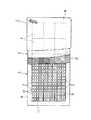
1 to 6 show a first embodiment of the present invention. 1 to 3 show a mattress 1 for a bed as a cushion device, and the mattress 1 has a three-layer structure of an upper
[0022]
The intermediate
[0023]
The
[0024]
The shape of the lattice of the
[0025]
Of the 15
[0026]
The elastomer used in the present invention is a thermoplastic elastomer or rubber. A thermoplastic elastomer is a substance that behaves as a rubber-like elastic body at room temperature but undergoes compositional deformation as the temperature rises. As thermoplastic elastomers, polystyrene-based thermoplastic elastomers, polyolefin-based thermoplastic elastomers, polyvinyl chloride-based thermoplastic elastomers, polyester-based thermoplastic elastomers, polyurethane-based thermoplastic elastomers, polyamide-based thermoplastic elastomers, 1,2-polybutadiene-based Examples thereof include thermoplastic elastomers, fluororubber-based thermoplastic elastomers, chlorinated polyethylene-based thermoplastic elastomers, and dynamically crosslinked thermoplastic elastomers.
[0027]
Moreover, natural rubber and synthetic rubber are used as rubber. Examples of the synthetic rubber include polybutadiene rubber, polyisoprene rubber, butadiene styrene rubber, butadiene acrylonitrile rubber, and isobutylene rubber.
[0028]
Of the above-described elastomers, polystyrene-based thermoplastic elastomers are particularly preferable for forming the
[0029]
The plurality of
[0030]
As the adhesive, for example, a synthetic rubber adhesive having flexibility at the time of curing is used. Thereby, the 15
[0031]
As shown in FIG. 4, the outer peripheral surface of the
[0032]
In the
[0033]
However, as described above, after the
[0034]
That is, when the
[0035]
In addition, the adhesive which adhere | attaches the
[0036]
The lower
[0037]
On the upper surface of the intermediate
[0038]
The upper
[0039]
According to the mattress 1 having such a configuration, since the upper
[0040]
As shown in FIG. 6, the intermediate
[0041]
A
[0042]
Since the lower
[0043]
For this reason, the lower
[0044]
The three
[0045]
Further, as described above, the
[0046]
In the first embodiment, an elastic support formed in a plate shape with a hard or semi-rigid elastic material is used as the lower
[0047]
FIG. 7 shows a second embodiment of the present invention. This embodiment is different from the first embodiment in the configuration of the cushion core. The
[0048]
The middle part in the longitudinal direction of each block 7a is formed hard, for example, by making at least the
[0049]
As a result, the user's buttocks that are supine on the mattress 1 are supported by the hardly formed portions of the respective blocks 7a, so that the buttocks can be prevented from sinking too deeply.
[0050]
In each of the first and second embodiments, the number of blocks used to form the cushion core is not limited. For example, in the first embodiment, the blocks are arranged in 3 rows and 5 columns. However, it may be located in 3
[0051]
【The invention's effect】
As described above, according to the present invention, since the upper elastic layer is made of a low-rebound elastic material, it gives a good feel to the user and supports the user's load in a distributed manner, and the intermediate elastic layer is made thin by the elastic material. Since the partition wall is made of a cushion core formed in a lattice shape, it exhibits good buffering properties, and the lower elastic layer is made of an elastic material that is harder than the intermediate elastic layer, so that the user's body can be given elasticity. It can be reliably supported.
[0052]
Therefore, it is possible to provide a cushion device that is excellent in touch, cushioning properties, support performance, and the like.
[Brief description of the drawings]
FIG. 1 is a partially sectional lower plan view of a mattress showing a first embodiment of the invention.
FIG. 2 is a cross-sectional view along the longitudinal direction.
FIG. 3 is a cross-sectional view showing a state where a user lies down.
FIG. 4 is a plan view showing a part of a cushion core having a correction sheet attached to the outer peripheral surface.
FIG. 5 is a plan view showing a part of a frame body to which a cushion core is stuck via a correction sheet.
FIG. 6 is a partial enlarged cross-sectional view showing a state in which an upper elastic layer and an intermediate elastic layer are deformed by a load.
FIG. 7 is a plan view of a cushion core showing another embodiment of the present invention.
[Explanation of symbols]
2 ... Upper
Claims (8)
Translated fromJapanese上記上部弾性層は板状の低反発弾性材料から形成され、
上記中間弾性層は弾性材料によって形成された枠体内に、弾性材料を射出成形して薄肉の隔壁が格子状に形成されたクッションコアを収容して形成され、
上記下部弾性層は上記中間弾性層よりも硬質な弾性材料によって形成されていて、
上記クッションコアの外周面には上記枠体と同じ弾性材料によって形成された矯正シートが接着され、上記枠体はこの矯正シートを介して上記枠体の内周面に接着固定されることを特徴とするクッション装置。A three-layer structure of an upper elastic layer, an intermediate elastic layer and a lower elastic layer,
The upper elastic layer is formed of a plate-like low rebound elastic material,
The intermediate elastic layer is formed by accommodating a cushion core in which a thin partition wall is formed in a lattice shapeby injection molding an elastic material in a frame formed of an elastic material,
The lower elastic layer is made of an elastic material harder than the intermediate elastic layer,
A correction sheet made of the same elastic material as that of the frame body is bonded to the outer peripheral surface of the cushion core, and the frame body is bonded and fixed to the inner peripheral surface of the frame body through the correction sheet. Cushion device.
Priority Applications (1)
| Application Number | Priority Date | Filing Date | Title |
|---|---|---|---|
| JP2001327883AJP3889265B2 (en) | 2001-10-25 | 2001-10-25 | Cushion device |
Applications Claiming Priority (1)
| Application Number | Priority Date | Filing Date | Title |
|---|---|---|---|
| JP2001327883AJP3889265B2 (en) | 2001-10-25 | 2001-10-25 | Cushion device |
Publications (2)
| Publication Number | Publication Date |
|---|---|
| JP2003125903A JP2003125903A (en) | 2003-05-07 |
| JP3889265B2true JP3889265B2 (en) | 2007-03-07 |
Family
ID=19144039
Family Applications (1)
| Application Number | Title | Priority Date | Filing Date |
|---|---|---|---|
| JP2001327883AExpired - Fee RelatedJP3889265B2 (en) | 2001-10-25 | 2001-10-25 | Cushion device |
Country Status (1)
| Country | Link |
|---|---|
| JP (1) | JP3889265B2 (en) |
Families Citing this family (1)
| Publication number | Priority date | Publication date | Assignee | Title |
|---|---|---|---|---|
| US20220338641A1 (en)* | 2021-04-27 | 2022-10-27 | Soft-Tex International, Inc. | Mattresses, cushions, and body-support pads or mats with deformable walls having fiber strands embedded therein |
- 2001
- 2001-10-25JPJP2001327883Apatent/JP3889265B2/ennot_activeExpired - Fee Related
Also Published As
| Publication number | Publication date |
|---|---|
| JP2003125903A (en) | 2003-05-07 |
Similar Documents
| Publication | Publication Date | Title |
|---|---|---|
| EP2373197B1 (en) | Thin-layered alternating material body support and method of manufacturing same | |
| EP0436022B1 (en) | Bed mat | |
| US4713854A (en) | Constant force cushion | |
| KR102773184B1 (en) | Ventilated mattresses | |
| KR100910945B1 (en) | Highly elastic cushion material and bed mattress using the same | |
| JP3121554U (en) | Three-dimensional lattice gel cushion | |
| US20040021361A1 (en) | Seat cushion assembly | |
| JP4221952B2 (en) | Elastic unit and mattress | |
| JP3889265B2 (en) | Cushion device | |
| JP6605128B2 (en) | Multilayer cushion and mattress with the same | |
| JP4815079B2 (en) | Cushion device | |
| KR102460166B1 (en) | A hybrid-mattress | |
| JP4733308B2 (en) | Cushion device | |
| KR101512801B1 (en) | Cushion mat | |
| JP3977993B2 (en) | Cushion device | |
| JP4866030B2 (en) | Mattress equipment | |
| JP2007083018A (en) | Elastic body unit and mat | |
| KR102285166B1 (en) | Mattress | |
| JP2004089526A (en) | Cushion device | |
| CN110801125A (en) | Hardness-adjustable cushion | |
| CN221083228U (en) | Soft and hard integrated gathering pressure release cushion | |
| JP2002209681A (en) | Cushion device | |
| JP3233327U (en) | sofa | |
| JP3221016U (en) | Seated cushion | |
| JP3003113B2 (en) | Cushion mat |
Legal Events
| Date | Code | Title | Description |
|---|---|---|---|
| A621 | Written request for application examination | Free format text:JAPANESE INTERMEDIATE CODE: A621 Effective date:20040824 | |
| A977 | Report on retrieval | Free format text:JAPANESE INTERMEDIATE CODE: A971007 Effective date:20060621 | |
| A131 | Notification of reasons for refusal | Free format text:JAPANESE INTERMEDIATE CODE: A131 Effective date:20060711 | |
| A521 | Written amendment | Free format text:JAPANESE INTERMEDIATE CODE: A523 Effective date:20060908 | |
| TRDD | Decision of grant or rejection written | ||
| A01 | Written decision to grant a patent or to grant a registration (utility model) | Free format text:JAPANESE INTERMEDIATE CODE: A01 Effective date:20061114 | |
| A61 | First payment of annual fees (during grant procedure) | Free format text:JAPANESE INTERMEDIATE CODE: A61 Effective date:20061129 | |
| R150 | Certificate of patent or registration of utility model | Ref document number:3889265 Country of ref document:JP Free format text:JAPANESE INTERMEDIATE CODE: R150 Free format text:JAPANESE INTERMEDIATE CODE: R150 | |
| FPAY | Renewal fee payment (event date is renewal date of database) | Free format text:PAYMENT UNTIL: 20091208 Year of fee payment:3 | |
| FPAY | Renewal fee payment (event date is renewal date of database) | Free format text:PAYMENT UNTIL: 20101208 Year of fee payment:4 | |
| FPAY | Renewal fee payment (event date is renewal date of database) | Free format text:PAYMENT UNTIL: 20101208 Year of fee payment:4 | |
| FPAY | Renewal fee payment (event date is renewal date of database) | Free format text:PAYMENT UNTIL: 20111208 Year of fee payment:5 | |
| FPAY | Renewal fee payment (event date is renewal date of database) | Free format text:PAYMENT UNTIL: 20111208 Year of fee payment:5 | |
| FPAY | Renewal fee payment (event date is renewal date of database) | Free format text:PAYMENT UNTIL: 20121208 Year of fee payment:6 | |
| FPAY | Renewal fee payment (event date is renewal date of database) | Free format text:PAYMENT UNTIL: 20121208 Year of fee payment:6 | |
| FPAY | Renewal fee payment (event date is renewal date of database) | Free format text:PAYMENT UNTIL: 20131208 Year of fee payment:7 | |
| FPAY | Renewal fee payment (event date is renewal date of database) | Free format text:PAYMENT UNTIL: 20131208 Year of fee payment:7 | |
| FPAY | Renewal fee payment (event date is renewal date of database) | Free format text:PAYMENT UNTIL: 20141208 Year of fee payment:8 | |
| FPAY | Renewal fee payment (event date is renewal date of database) | Free format text:PAYMENT UNTIL: 20141208 Year of fee payment:8 | |
| FPAY | Renewal fee payment (event date is renewal date of database) | Free format text:PAYMENT UNTIL: 20151208 Year of fee payment:9 | |
| LAPS | Cancellation because of no payment of annual fees |