JP3889090B2 - Sheet holding device - Google Patents
Sheet holding deviceDownload PDFInfo
- Publication number
- JP3889090B2 JP3889090B2JP22645896AJP22645896AJP3889090B2JP 3889090 B2JP3889090 B2JP 3889090B2JP 22645896 AJP22645896 AJP 22645896AJP 22645896 AJP22645896 AJP 22645896AJP 3889090 B2JP3889090 B2JP 3889090B2
- Authority
- JP
- Japan
- Prior art keywords
- sheet
- frame
- holding device
- liquid crystal
- sheets
- Prior art date
- Legal status (The legal status is an assumption and is not a legal conclusion. Google has not performed a legal analysis and makes no representation as to the accuracy of the status listed.)
- Expired - Fee Related
Links
Images


Classifications
- G—PHYSICS
- G02—OPTICS
- G02F—OPTICAL DEVICES OR ARRANGEMENTS FOR THE CONTROL OF LIGHT BY MODIFICATION OF THE OPTICAL PROPERTIES OF THE MEDIA OF THE ELEMENTS INVOLVED THEREIN; NON-LINEAR OPTICS; FREQUENCY-CHANGING OF LIGHT; OPTICAL LOGIC ELEMENTS; OPTICAL ANALOGUE/DIGITAL CONVERTERS
- G02F1/00—Devices or arrangements for the control of the intensity, colour, phase, polarisation or direction of light arriving from an independent light source, e.g. switching, gating or modulating; Non-linear optics
- G02F1/01—Devices or arrangements for the control of the intensity, colour, phase, polarisation or direction of light arriving from an independent light source, e.g. switching, gating or modulating; Non-linear optics for the control of the intensity, phase, polarisation or colour
- G02F1/13—Devices or arrangements for the control of the intensity, colour, phase, polarisation or direction of light arriving from an independent light source, e.g. switching, gating or modulating; Non-linear optics for the control of the intensity, phase, polarisation or colour based on liquid crystals, e.g. single liquid crystal display cells
- G02F1/133—Constructional arrangements; Operation of liquid crystal cells; Circuit arrangements
- G02F1/1333—Constructional arrangements; Manufacturing methods
- G02F1/1335—Structural association of cells with optical devices, e.g. polarisers or reflectors
- G02F1/1336—Illuminating devices
- G—PHYSICS
- G02—OPTICS
- G02F—OPTICAL DEVICES OR ARRANGEMENTS FOR THE CONTROL OF LIGHT BY MODIFICATION OF THE OPTICAL PROPERTIES OF THE MEDIA OF THE ELEMENTS INVOLVED THEREIN; NON-LINEAR OPTICS; FREQUENCY-CHANGING OF LIGHT; OPTICAL LOGIC ELEMENTS; OPTICAL ANALOGUE/DIGITAL CONVERTERS
- G02F1/00—Devices or arrangements for the control of the intensity, colour, phase, polarisation or direction of light arriving from an independent light source, e.g. switching, gating or modulating; Non-linear optics
- G02F1/01—Devices or arrangements for the control of the intensity, colour, phase, polarisation or direction of light arriving from an independent light source, e.g. switching, gating or modulating; Non-linear optics for the control of the intensity, phase, polarisation or colour
- G02F1/13—Devices or arrangements for the control of the intensity, colour, phase, polarisation or direction of light arriving from an independent light source, e.g. switching, gating or modulating; Non-linear optics for the control of the intensity, phase, polarisation or colour based on liquid crystals, e.g. single liquid crystal display cells
- G02F1/133—Constructional arrangements; Operation of liquid crystal cells; Circuit arrangements
- G02F1/1333—Constructional arrangements; Manufacturing methods
- G02F1/1335—Structural association of cells with optical devices, e.g. polarisers or reflectors
- G—PHYSICS
- G02—OPTICS
- G02B—OPTICAL ELEMENTS, SYSTEMS OR APPARATUS
- G02B5/00—Optical elements other than lenses
- G02B5/20—Filters
- G—PHYSICS
- G02—OPTICS
- G02F—OPTICAL DEVICES OR ARRANGEMENTS FOR THE CONTROL OF LIGHT BY MODIFICATION OF THE OPTICAL PROPERTIES OF THE MEDIA OF THE ELEMENTS INVOLVED THEREIN; NON-LINEAR OPTICS; FREQUENCY-CHANGING OF LIGHT; OPTICAL LOGIC ELEMENTS; OPTICAL ANALOGUE/DIGITAL CONVERTERS
- G02F1/00—Devices or arrangements for the control of the intensity, colour, phase, polarisation or direction of light arriving from an independent light source, e.g. switching, gating or modulating; Non-linear optics
- G02F1/01—Devices or arrangements for the control of the intensity, colour, phase, polarisation or direction of light arriving from an independent light source, e.g. switching, gating or modulating; Non-linear optics for the control of the intensity, phase, polarisation or colour
- G02F1/13—Devices or arrangements for the control of the intensity, colour, phase, polarisation or direction of light arriving from an independent light source, e.g. switching, gating or modulating; Non-linear optics for the control of the intensity, phase, polarisation or colour based on liquid crystals, e.g. single liquid crystal display cells
- G02F1/133—Constructional arrangements; Operation of liquid crystal cells; Circuit arrangements
- G02F1/1333—Constructional arrangements; Manufacturing methods
- G02F1/1335—Structural association of cells with optical devices, e.g. polarisers or reflectors
- G02F1/1336—Illuminating devices
- G02F1/133615—Edge-illuminating devices, i.e. illuminating from the side
- G—PHYSICS
- G02—OPTICS
- G02F—OPTICAL DEVICES OR ARRANGEMENTS FOR THE CONTROL OF LIGHT BY MODIFICATION OF THE OPTICAL PROPERTIES OF THE MEDIA OF THE ELEMENTS INVOLVED THEREIN; NON-LINEAR OPTICS; FREQUENCY-CHANGING OF LIGHT; OPTICAL LOGIC ELEMENTS; OPTICAL ANALOGUE/DIGITAL CONVERTERS
- G02F1/00—Devices or arrangements for the control of the intensity, colour, phase, polarisation or direction of light arriving from an independent light source, e.g. switching, gating or modulating; Non-linear optics
- G02F1/01—Devices or arrangements for the control of the intensity, colour, phase, polarisation or direction of light arriving from an independent light source, e.g. switching, gating or modulating; Non-linear optics for the control of the intensity, phase, polarisation or colour
- G02F1/13—Devices or arrangements for the control of the intensity, colour, phase, polarisation or direction of light arriving from an independent light source, e.g. switching, gating or modulating; Non-linear optics for the control of the intensity, phase, polarisation or colour based on liquid crystals, e.g. single liquid crystal display cells
- G02F1/133—Constructional arrangements; Operation of liquid crystal cells; Circuit arrangements
- G02F1/1333—Constructional arrangements; Manufacturing methods
- G02F1/133308—Support structures for LCD panels, e.g. frames or bezels
- G02F1/133317—Intermediate frames, e.g. between backlight housing and front frame
- G—PHYSICS
- G02—OPTICS
- G02F—OPTICAL DEVICES OR ARRANGEMENTS FOR THE CONTROL OF LIGHT BY MODIFICATION OF THE OPTICAL PROPERTIES OF THE MEDIA OF THE ELEMENTS INVOLVED THEREIN; NON-LINEAR OPTICS; FREQUENCY-CHANGING OF LIGHT; OPTICAL LOGIC ELEMENTS; OPTICAL ANALOGUE/DIGITAL CONVERTERS
- G02F2202/00—Materials and properties
- G02F2202/28—Adhesive materials or arrangements
Landscapes
- Physics & Mathematics (AREA)
- Nonlinear Science (AREA)
- General Physics & Mathematics (AREA)
- Optics & Photonics (AREA)
- Mathematical Physics (AREA)
- Chemical & Material Sciences (AREA)
- Crystallography & Structural Chemistry (AREA)
- Liquid Crystal (AREA)
- Planar Illumination Modules (AREA)
- Mounting And Adjusting Of Optical Elements (AREA)
- Optical Filters (AREA)
Description
Translated fromJapanese【0001】
【発明の属する技術分野】
本発明は、所定の光学特性を有したシートを備えたシート保持装置に関する。
【0002】
【従来の技術】
従来、所定の光学特性を有したシートを備えたシート保持装置が用いられている。そして、このシート保持装置では、シートの周縁部に沿った枠状をなす枠部と、この枠部の各辺に取り付けられる押さえ部材となるサイドカバーとを備え、これら枠部とサイドカバーとの間に、シートの相対向する2辺を挟持して支持し、枠体にシートを取り付けている。
【0003】
【発明が解決しようとする課題】
しかしながら、上記従来のように、シートの相対向する2辺をサイドカバーを用いて押さえる構成では、シートを正確に位置決めし、枠体に沿って張り詰めた状態で保持しないと、シートにうねりが生じ、光学特性が低下するとともに、シートの交換作業はシートを傷付けやすい煩雑な作業となり、さらに、部品点数の削減が困難で製造コストの低減が困難である問題を有している。
【0004】
本発明は、このような点に鑑みなされたもので、シートを枠体に容易に保持できるシート保持装置を提供することを目的とする。
【0005】
【課題を解決するための手段】
本発明のシート保持装置は、一辺に延設された耳部を備えた光学特性を有するシートと、このシートの周縁部に沿って配置された枠部を備えた枠体と、前記シートを前記枠体に保持させるべく前記耳部を前記枠体に貼着する貼着手段とを具備したものである。そして、この構成により、部品点数が削減されるとともに、シートをうねることなく枠体に沿って容易に配置でき、シートの交換作業も容易になる。
【0006】
また、互いに積層される複数のシートを備え、各シートの耳部は、互いに位置をずらして配置され、それぞれ貼着手段を用いて枠体に貼着された構成により、貼着手段を設けた部分の厚さ寸法の増加が抑制されるとともに、各シート同士の間に入った異物の除去も容易になる。
【0007】
【発明の実施の形態】
以下、本発明のシート保持装置の一実施の形態を図面を参照して説明する。
【0008】
図2および図3において、1は液晶表示装置で、この液晶表示装置1は、画像を表示する表示手段である液晶パネル2、照明装置であるバックライト装置3、および回路基板4などを組み合わせて構成されている。なお、以下、液晶パネル2の表示面側(正面側)を上側として説明する。
【0009】
そして、液晶パネル2は、液晶セル、液晶表示素子あるいはこれ自体が液晶表示装置などとも呼ばれるもので、TFTトランジスタを設けたアレイ基板(TFT)6と、このアレイ基板6の上側に対向して設けられたカラーフィルタ基板(CF、対向基板)7とを備え、これら透光性を有する基板6,7間に液晶が注入されている。さらに、この液晶パネル2に回路基板4が電気的に接続され、この回路基板4により液晶パネル2が駆動され、画像の表示を行うようになっている。
【0010】
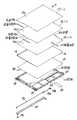
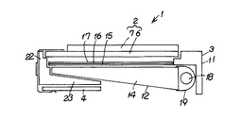
また、図1ないし図3に示すように、バックライト装置3は、合成樹脂(プラスチック)などにて一体に成型された枠体としてのプラフレーム11を備え、このプラフレーム11の上側に、順次、反射シート12、導光体14、シートとしての拡散シート15、シートとしての第1プリズムシート16、シートとしての第2プリズムシート17を積層し、さらに、導光体14の一側部に位置して、光源となるランプ18、ランプリフレクタ19、およびランプカバー20を取り付けている。
【0011】
そして、プラフレーム11は、プラスチックモールドなどとも呼ばれるもので、略四角枠状をなす枠部22が形成されているとともに、この枠部22の内側に位置して回路基板取付部23が形成され、さらに、枠部22の外側の四隅の近傍に位置して、それぞれねじ止め部24が形成されている。また、枠部22の内周部は、上側に向かって拡開するように階段状に形成され、図3に示すように、導光体受面部22a 、シート受面部22b 、および液晶パネル受面部22c が設けられている。
【0012】
そして、このプラフレーム11の導光体受面部22a の上側には、上面を反射面とする反射シート12が配置されて、両面テープ25を用いて接着され、さらに、この反射シート12の上側に、導光体14が配置されている。そして、この導光体14は、導光板とも呼ばれるもので、上面が水平状の発光面であるのに対して、下面が傾斜面となり、一側の端部から他側の端部に向かって厚さ寸法が次第に薄くなる略楔形に形成されている。
【0013】
また、この導光体14の一側の端部に沿って、ランプ18が配置されるとともに、このランプ18を覆うようにして、導光体14側を照射開口とするランプリフレクタ19が取り付けられ、さらに、これらランプ18およびランプリフレクタ19を覆い、、ねじ止め部24にねじ止めされるねじ26にてランプカバー20が固定されている。そして、ランプ18は、蛍光ランプである細径の冷陰極管で、一端部にリード線18a を介して端子部18b が接続され、また、両端部にシリコーン系のゴムホルダが備えられている。そして、このランプ18から照射される光線が、導光体14の内部で反射を繰り返した上、上面から上方に出射されるようになっている。
【0014】
そして、この導光体14の上面に沿って、拡散シート15、第1プリズムシート16、および第2プリズムシート17が順次積層されている。そして、これらシート15,16,17は、それぞれ平面矩形状をなすシート本体15a ,16a ,17a と、このシート本体15a ,16a ,17a のそれぞれ一辺のみの一部から延設された耳部15b ,16b ,17b とが一体に形成されている。そして、これらシート本体15a ,16a ,17a は、それぞれ所定の光学特性を有し、すなわち、拡散シート15は、ウェーブシートなどとも呼ばれるもので、例えば乳白色などをなして、入射した光線をほぼ均等に拡散させる。また、第1および第2のプリズムシート16,17は、例えば、ポリカーボネートなどのプラスチックフィルムの上面全面に、頂角が90度〜100度の微小なプリズムを数十〜数百μmピッチで形成したもので、下面すなわち平面側から入射した光を屈折し、プラスマイナス40度の狭い拡散光として上方に出射し、上面すなわち正面から見た場合の輝度を向上するようになっている。そして、これら第1プリズムシート16のシート本体16a と、第2プリズムシート17のシート本体17a とでは、プリズムの長手方向が互いに直交するように、すなわち縦縞と横縞となるように配置されている。
【0015】
さらに、図4などに示すように、これらシート15,16,17の耳部15b ,16b ,17b は、互いに上下に重ならないように、水平方向に位置をずらして形成されている。すなわち、拡散シート15の耳部15b は、一端部の中央部から延設されているとともに、第1プリズムシート16の耳部16b は、他端部の一側部から延設され、さらに、第2プリズムシート17の耳部17b は、他端部の中央部から延設されている。そして、これら耳部15b ,16b ,17b は、それぞれ貼着手段としての両面テープ31,32,33を用いて、プラフレーム11の枠部22のシート受面部22b 上に接着されている。
【0016】
そして、これらシート15,16,17の上側に必要に応じて保護シートを配置した上で、図2および図3に示すように、シート15,16,17の上側に位置して、枠部22の液晶パネル受面部22c 上に液晶パネル2を配置し、さらに、回路基板取付部23の下側に回路基板4を配置して、ねじ26などにて固定することにより、液晶表示装置1が組み立てられている。そして、この状態で、各シート15,16,17は、導光体14の上面の発光面と液晶パネル2の下面との間に挟持されるようにして保持されている。
【0017】
そして、この実施の形態では、ランプ18を点灯させることにより、導光体14の発光面が面状に発光し、拡散シート15でさらに拡散された上、第1および第2のプリズムシート16,17で照射方向が調整され、液晶パネル2が背面から照明されるようになっている。
【0018】
また、この液晶表示装置1の所定の位置には、廃棄方法などを示す廃棄ラベル35が貼付されている。
【0019】
そして、本実施の形態によれば、バックライト装置3に備えられる、それぞれ所定の光学特性を有するシート15,16,17の押さえ方法について、各シート15,16,17のシート本体15a ,16a ,17a の一辺に耳部15b ,16b ,17b を設け、この耳部15b ,16b ,17b を両面テープ31,32,33を用いてプラフレーム11に固定している。そこで、各シート15,16,17は、1辺のみが固定されるため、複数の辺を固定する構造で、特に、いわゆる信頼性試験などの際に生じやすいうねり(しわ)の発生を抑制し、各シート15,16,17を導光体14に沿って容易に平滑に配置することができる。そこで、各シート15,16,17のうねりによって生じる輝度むらを抑制し、光学特性の信頼性を向上することができる。
【0020】
また、本実施の形態によれば、各シート15,16,17は、1辺のみが固定されるため、各シート15,16,17間に入った異物(ごみ)の除去が容易になるとともに、各シート15,16,17の交換も容易になり、サイドカバーなどを用いてシートを固定する構成に比べて、シート15,16,17の交換時にこれらシート15,16,17を傷付けることを抑制することができ、傷付きやすいプリズムシート16,17のメンテナンスを容易にすることができる。
【0021】
さらに、本実施の形態によれば、サイドカバーなどを用いてシートを固定する構成に比べて、部品点数を削減し、製造コストを低減することができる。
【0022】
また、各シート15,16,17の耳部15b ,16b ,17b は、水平方向に位置をずらして形成し、互いに上下に重ならないようにしたため、耳部15b ,16b ,17b と両面テープ31,32,33とが積層されることがなく、この耳部15b ,16b ,17b の部分のみの厚さ寸法が大きくなることを抑制して、厚さ寸法を均一化することができる。
【0023】
なお、上記の実施の形態では、貼着手段として、両面テープ31,32,33を用いたが、例えば、接着剤を用いたのり部として形成することもできる。
【0024】
また、上記の実施の形態では、シートとして、1枚の拡散シート15と2枚のプリズムシート16,17とを積層したが、シートは種々の構成を採ることが可能であり、種々の光学特性を有したシートを用いて、1枚のみ、あるいは2枚以上のシートを積層して用いることができる。
【0025】
さらに、上記の実施の形態では、導光体14の一辺に沿ってランプ18を配置した構成について説明したが、例えば、導光体14の二辺に沿ってランプ18を配置することもできる。
【0026】
【発明の効果】
本発明のシート保持装置によれば、シートの一辺から耳部を延設し、貼着手段を用いてこの耳部を枠体に貼着したため、部品点数を削減し、製造コストを低減できるとともに、シートをうねることなく枠体に沿って容易に配置でき光学特性を向上でき、さらに、シートの交換作業も容易にすることができる。
また、互いに積層される複数のシートを備え、各シートの耳部を、互いに位置をずらして配置し、それぞれ貼着手段を用いて枠体に貼着する構成により、貼着手段を設けた部分の厚さ寸法の増加を抑制でき、積層したシートの厚さの均一化を図ることができるとともに、各シート同士の間に入った異物を容易に除去することができる。
【図面の簡単な説明】
【図1】 本発明のシート保持装置の一実施の形態を示すシート保持装置を備えたバックライト装置の分解斜視図である。
【図2】 同上シート保持装置を備えた液晶表示装置の概略を示す断面図である。
【図3】 同上図2の一部を拡大した断面図である。
【図4】 同上シート保持装置の平面図である。
【符号の説明】
11 枠体としてのプラフレーム
15 シートとしての拡散シート
16 シートとしての第1プリズムシート
17 シートとしての第2プリズムシート
15b ,16b ,17b 耳部
22 枠部
31,32,33 貼着手段としての両面テープ[0001]
BACKGROUND OF THE INVENTION
The present invention relates to asheet holding device including asheet having predetermined optical characteristics.
[0002]
[Prior art]
Conventionally, asheet holding device including asheet having predetermined optical characteristics has been used. Thesheet holding device includes a frame portion that forms a frame shape along the peripheral edge portion of the sheet, and a side cover that serves as a pressing member attached to each side of the frame portion. The sheet is attached to the frame by sandwiching and supporting two opposite sides of the sheet.
[0003]
[Problems to be solved by the invention]
However, in the configuration in which the two opposite sides of the sheet are pressed using the side cover as in the conventional case, if the sheet is not positioned accurately and held along the frame, the sheet will swell. As a result, the optical properties are deteriorated, and the sheet replacement operation is a complicated operation that easily damages the sheet. Further, it is difficult to reduce the number of components and to reduce the manufacturing cost.
[0004]
SUMMARY An advantage of some aspects of the invention is that it provides asheet holding device that can easily hold a sheet in a frame.
[0005]
[Means for Solving the Problems]
Sheet retaining device of the present invention, a frame having a seatwhich have the optical propertieswith ear portion extending to one side, a frame portion disposed along the periphery ofthe sheet,the sheet And a sticking means for sticking the ear to the frameso as to be held by the frame. With this configuration, the number of parts is reduced, and the sheet can be easily arranged along the frame without undulating the sheet, and the sheet can be easily replaced.
[0006]
In addition, a plurality of sheets that are stacked on each other are provided, and the ears of each sheet are arranged so as to be shifted from each other, and are each provided with an adhering unit by a configuration that is adhering to the frame using the adhering unit. The increase in the thickness dimension of the part is suppressed, and the removal of foreign matter that has entered between the sheets is facilitated.
[0007]
DETAILED DESCRIPTION OF THE INVENTION
Hereinafter, an embodiment of asheet holding device of the present invention will be described with reference to the drawings.
[0008]
2 and 3, reference numeral 1 denotes a liquid crystal display device. The liquid crystal display device 1 is a combination of a liquid crystal panel 2 that is a display means for displaying an image, a
[0009]
The liquid crystal panel 2 is also called a liquid crystal cell, a liquid crystal display element, or a liquid crystal display device itself. The liquid crystal panel 2 is provided so as to face the array substrate (TFT) 6 provided with TFT transistors and the upper side of the array substrate 6. A liquid crystal is injected between the
[0010]
Further, as shown in FIGS. 1 to 3, the
[0011]
The
[0012]
Then, on the upper side of the light guide body receiving
[0013]
A
[0014]
A
[0015]
Further, as shown in FIG. 4 and the like, the
[0016]
Then, a protective sheet is arranged on the upper side of the
[0017]
In this embodiment, when the
[0018]
Further, a
[0019]
And according to this Embodiment, about the pressing method of the sheet |
[0020]
Further, according to the present embodiment, since each
[0021]
Furthermore, according to the present embodiment, the number of parts can be reduced and the manufacturing cost can be reduced as compared with the configuration in which the seat is fixed using a side cover or the like.
[0022]
In addition, the
[0023]
In the above embodiment, the double-sided tapes 31, 32, and 33 are used as the adhering means. However, for example, they can be formed as a glue portion using an adhesive.
[0024]
In the above-described embodiment, one
[0025]
Furthermore, in the above-described embodiment, the configuration in which the
[0026]
【The invention's effect】
According to thesheet holding device of the present invention, by extending ears fromone sideof the sheet, due to stuck the ear portion to the frame using a sticking means, to reduce the number of parts, the manufacturing cost can be reduced At the same time, the sheet can be easily arranged along the frame without undulation, the optical characteristics can be improved, and the replacement work of the sheet can be facilitated.
In addition, a part provided with a plurality of sheets stacked on each other, with the ears of each sheet disposed at a different position from each other, and affixing means to each other using a sticking means. The increase in the thickness dimension of the sheet can be suppressed, the thickness of the stacked sheets can be made uniform, and the foreign matter that has entered between the sheets can be easily removed.
[Brief description of the drawings]
FIG. 1 is an exploded perspective view of a backlight device including asheet holding device according to an embodiment of thesheet holding device of the present invention.
FIG. 2 is a cross-sectional view schematically showing a liquid crystal display device provided with thesheet holding device.
FIG. 3 is an enlarged sectional view of a part of FIG. 2;
FIG. 4 is a plan view of thesheet holding device.
[Explanation of symbols]
11 Plastic frame as a frame
15 Diffusion sheet as a sheet
16 First prism sheet as a sheet
17 second prismsheet as a sheet
15b, 16b, 17b Ear
22 Frame
31, 32, 33 Double-sided tape as a means of sticking
Claims (2)
Translated fromJapaneseこのシートの周縁部に沿って配置された枠部を備えた枠体と、
前記シートを前記枠体に保持させるべく前記耳部を前記枠体に貼着する貼着手段と
を具備したことを特徴とするシート保持装置。Andsheet have the optical propertieswith ear portion extending to one side,
A frame body provided with a frame portion arranged along the peripheral edge portion of thesheet ;
Asheet holding device comprising: an attaching unit that attaches the ear portion to the frameso as to hold the sheet to the frame .
各シートの耳部は、互いに位置をずらして配置され、それぞれ貼着手段を用いて枠体に貼着された
ことを特徴とする請求項1記載のシート保持装置。Comprising a plurality of sheets laminated together,
Thesheet holding device according to claim 1, wherein the ears of each sheet are arranged with their positions shifted from each other, and each sheet is attached to the frame using an attaching means.
Priority Applications (5)
| Application Number | Priority Date | Filing Date | Title |
|---|---|---|---|
| JP22645896AJP3889090B2 (en) | 1996-08-28 | 1996-08-28 | Sheet holding device |
| TW086111611ATW531683B (en) | 1996-08-28 | 1997-08-13 | Filter device and backlight device |
| US08/917,740US5999238A (en) | 1996-08-28 | 1997-08-27 | Filter device and backlight device |
| KR1019970041322AKR100236311B1 (en) | 1996-08-28 | 1997-08-27 | Filter device and backlight apparatus |
| US09/378,920US6163350A (en) | 1996-08-28 | 1999-08-23 | Filter device and backlight device, each filter sheet having only one holding portion which is bonded to a frame member |
Applications Claiming Priority (1)
| Application Number | Priority Date | Filing Date | Title |
|---|---|---|---|
| JP22645896AJP3889090B2 (en) | 1996-08-28 | 1996-08-28 | Sheet holding device |
Publications (2)
| Publication Number | Publication Date |
|---|---|
| JPH1068857A JPH1068857A (en) | 1998-03-10 |
| JP3889090B2true JP3889090B2 (en) | 2007-03-07 |
Family
ID=16845419
Family Applications (1)
| Application Number | Title | Priority Date | Filing Date |
|---|---|---|---|
| JP22645896AExpired - Fee RelatedJP3889090B2 (en) | 1996-08-28 | 1996-08-28 | Sheet holding device |
Country Status (4)
| Country | Link |
|---|---|
| US (2) | US5999238A (en) |
| JP (1) | JP3889090B2 (en) |
| KR (1) | KR100236311B1 (en) |
| TW (1) | TW531683B (en) |
Families Citing this family (38)
| Publication number | Priority date | Publication date | Assignee | Title |
|---|---|---|---|---|
| JP3257457B2 (en)* | 1997-07-31 | 2002-02-18 | 株式会社日立製作所 | Liquid crystal display |
| KR100290775B1 (en)* | 1997-12-17 | 2001-06-01 | 박종섭 | Back light unit without mold frame of liquid crystal display |
| US6292239B1 (en) | 1998-05-28 | 2001-09-18 | Matsushita Electric Industrial Co., Ltd. | Liquid crystal display having frame to hold the panel and the back light unit using notch and tabs |
| US6501641B1 (en)* | 1998-10-23 | 2002-12-31 | Lg. Philips Lcd Co. Ltd. | Portable computer having a flat panel display device |
| JP2001051619A (en)* | 1999-08-05 | 2001-02-23 | Toshiba Corp | Flat panel display |
| KR100396771B1 (en)* | 2001-01-13 | 2003-09-03 | 엘지전자 주식회사 | The liquid crystal display apparatus and the mobile terminal |
| JP2002258249A (en)* | 2001-03-05 | 2002-09-11 | Nec Corp | Liquid crystal display and its assembling method |
| JP4945032B2 (en)* | 2001-05-08 | 2012-06-06 | 恵和株式会社 | Reflective sheet and backlight unit using the same |
| JP2003043484A (en)* | 2001-08-03 | 2003-02-13 | Fujitsu Ltd | Liquid crystal display |
| US6906761B2 (en)* | 2001-09-19 | 2005-06-14 | Keiwa Inc. | Reflection sheet and backlight unit using the same |
| KR100438549B1 (en)* | 2001-11-09 | 2004-07-03 | 엘지전자 주식회사 | Lcd apparatus for mobile phone |
| KR100595304B1 (en)* | 2001-12-26 | 2006-07-03 | 엘지.필립스 엘시디 주식회사 | Lamp wire fixing structure of LCD |
| KR100855499B1 (en)* | 2001-12-29 | 2008-09-01 | 엘지디스플레이 주식회사 | LCD Display |
| KR100720626B1 (en) | 2003-02-17 | 2007-05-21 | 샤프 가부시키가이샤 | Chassis for a flat-panel display device, flat-panel display device, liquid crystal panel display device and chassis unit for a flat-panel display device |
| JP4217090B2 (en)* | 2003-03-20 | 2009-01-28 | 株式会社 日立ディスプレイズ | Display device |
| US7488105B2 (en)* | 2004-05-28 | 2009-02-10 | Heng-Sheng Kuo | Backlight module |
| JP4631350B2 (en)* | 2004-08-17 | 2011-02-16 | セイコーエプソン株式会社 | LIGHTING DEVICE, LIQUID CRYSTAL DISPLAY DEVICE, AND ELECTRONIC DEVICE |
| KR20060089020A (en)* | 2005-02-03 | 2006-08-08 | 삼성전자주식회사 | Back light assembly and display device having same |
| KR100717784B1 (en)* | 2005-02-24 | 2007-05-11 | 삼성에스디아이 주식회사 | Plasma display device |
| US7279387B2 (en)* | 2005-02-25 | 2007-10-09 | United Microelectronics Corp. | Method for fabricating asymmetric semiconductor device |
| KR101272256B1 (en)* | 2006-03-20 | 2013-06-13 | 삼성디스플레이 주식회사 | Container Member, Manufacturing Method of Container Member and Flat Panel Display Using the Same |
| WO2007148444A1 (en)* | 2006-06-21 | 2007-12-27 | Sharp Kabushiki Kaisha | Light source unit and display |
| US7821590B2 (en)* | 2007-04-06 | 2010-10-26 | Tpo Displays Corp. | Assembly structure and process for a backlight device of a display system |
| TWI412835B (en)* | 2008-10-22 | 2013-10-21 | Innolux Corp | Backlight module, display device and fabricating method thereof |
| JP2011203639A (en)* | 2010-03-26 | 2011-10-13 | Hitachi Displays Ltd | Liquid crystal display device |
| WO2012063729A1 (en)* | 2010-11-11 | 2012-05-18 | シャープ株式会社 | Display device |
| WO2012153514A1 (en)* | 2011-05-12 | 2012-11-15 | シャープ株式会社 | Illumination device and liquid crystal display device |
| WO2012157547A1 (en)* | 2011-05-18 | 2012-11-22 | シャープ株式会社 | Display device |
| US9158340B2 (en) | 2011-06-27 | 2015-10-13 | Hand Held Products, Inc. | Apparatus and method for assembling display of indicia reading terminal |
| SG193229A1 (en)* | 2012-03-05 | 2013-10-30 | Skg Co Ltd | Light guide plate, display unit including the light guide plate, traffic sign including the display unit, and method of manufacturing the light guide plate and method of manufacturing the traffic sign |
| KR101552762B1 (en)* | 2013-04-12 | 2015-09-11 | 엘지디스플레이 주식회사 | Liquid crystal display device |
| CN205316158U (en)* | 2016-01-04 | 2016-06-15 | 京东方科技集团股份有限公司 | Optics diaphragm, backlight unit and display panel |
| JP2017188304A (en)* | 2016-04-05 | 2017-10-12 | 株式会社ジャパンディスプレイ | Backlight device and display device including the same |
| US20190204678A1 (en)* | 2016-09-05 | 2019-07-04 | Sharp Kabushiki Kaisha | Lighting device and display device |
| TWI611245B (en)* | 2017-02-23 | 2018-01-11 | 友達光電股份有限公司 | Optical film, optical film assembly and backlight module with lug design |
| CN109751532A (en)* | 2017-11-02 | 2019-05-14 | 苏州璨鸿光电有限公司 | Backlight module and optical diaphragm localization method |
| CN108153023B (en)* | 2018-01-18 | 2021-03-23 | Oppo广东移动通信有限公司 | Display screen and electronic equipment |
| CN113055559B (en)* | 2019-12-27 | 2022-12-09 | 荣耀终端有限公司 | Camera module and terminal equipment |
Family Cites Families (19)
| Publication number | Priority date | Publication date | Assignee | Title |
|---|---|---|---|---|
| US4294517A (en)* | 1979-05-14 | 1981-10-13 | Timex Corporation | Electrooptical device with encapsulated self-luminous backlight assembly |
| US4799771A (en)* | 1985-01-22 | 1989-01-24 | Sharp Kabushiki Kaisha | Liquid crystal display with stopper pins in guide means |
| US4963001A (en)* | 1988-08-23 | 1990-10-16 | Citizen Watch Co., Ltd. | Liquid crystal display device |
| JPH07121097B2 (en)* | 1988-11-18 | 1995-12-20 | 株式会社日立製作所 | Liquid crystal television and manufacturing method thereof |
| US5002368A (en)* | 1989-05-31 | 1991-03-26 | Poqet Computer Corporation | Liquid crystal display mounting structure |
| US5182660A (en)* | 1990-08-03 | 1993-01-26 | Rohm Co., Ltd. | Back-light type liquid crystal display |
| JPH0511264A (en)* | 1991-07-05 | 1993-01-19 | Hitachi Ltd | Liquid crystal display device |
| US5220442A (en)* | 1991-09-06 | 1993-06-15 | Xerox Corporation | Method of making color liquid crystal display with dead front appearance |
| JP2724642B2 (en)* | 1991-09-10 | 1998-03-09 | シャープ株式会社 | Liquid crystal display |
| JP3205373B2 (en)* | 1992-03-12 | 2001-09-04 | 株式会社日立製作所 | Liquid crystal display |
| US5422751A (en)* | 1992-10-14 | 1995-06-06 | Apple Computer, Inc. | Liquid crystal display assembly employing front bezel, frame holding liquid crystal cell attached to bezel, and light source and back plate attached to bezel |
| US5504605A (en)* | 1993-06-02 | 1996-04-02 | Hitachi, Ltd. | Liquid crystal display module having cut-away portions of the back frame for weight reduction and heat dissipation |
| BE1007433A3 (en)* | 1993-07-30 | 1995-06-13 | Philips Electronics Nv | PLATTE image display apparatus, illumination system RADIATION SOURCE AND SUITABLE FOR APPLICATION IN SUCH A flat picture display device. |
| US5479285A (en)* | 1993-09-01 | 1995-12-26 | Ncr Corporation | Liquid crystal device with an isotropic shock mounting and gasket |
| US5668649A (en)* | 1994-03-07 | 1997-09-16 | Hitachi, Ltd. | Structure of liquid crystal display device for antireflection |
| US5640216A (en)* | 1994-04-13 | 1997-06-17 | Hitachi, Ltd. | Liquid crystal display device having video signal driving circuit mounted on one side and housing |
| JP3184730B2 (en)* | 1995-03-03 | 2001-07-09 | インターナショナル・ビジネス・マシーンズ・コーポレ−ション | Portable information processing device |
| TW453449U (en)* | 1995-11-16 | 2001-09-01 | Hitachi Ltd | LCD display panel with buckling driving multi-layer bendable PCB |
| JP3296993B2 (en)* | 1997-04-08 | 2002-07-02 | エルジー フィリップス エルシーディー カンパニー リミテッド | Portable computer with liquid crystal display |
- 1996
- 1996-08-28JPJP22645896Apatent/JP3889090B2/ennot_activeExpired - Fee Related
- 1997
- 1997-08-13TWTW086111611Apatent/TW531683B/ennot_activeIP Right Cessation
- 1997-08-27USUS08/917,740patent/US5999238A/ennot_activeExpired - Lifetime
- 1997-08-27KRKR1019970041322Apatent/KR100236311B1/ennot_activeExpired - Lifetime
- 1999
- 1999-08-23USUS09/378,920patent/US6163350A/ennot_activeExpired - Lifetime
Also Published As
| Publication number | Publication date |
|---|---|
| TW531683B (en) | 2003-05-11 |
| KR19980019044A (en) | 1998-06-05 |
| US6163350A (en) | 2000-12-19 |
| US5999238A (en) | 1999-12-07 |
| KR100236311B1 (en) | 1999-12-15 |
| JPH1068857A (en) | 1998-03-10 |
Similar Documents
| Publication | Publication Date | Title |
|---|---|---|
| JP3889090B2 (en) | Sheet holding device | |
| KR101690022B1 (en) | Back-light assembly and display device having the same | |
| CN105785498A (en) | Backlight module group and liquid crystal display device | |
| JP4169296B2 (en) | Surface light source device | |
| CN101813852A (en) | Liquid crystal display device having a plurality of pixel electrodes | |
| JP2017120310A (en) | Display device, adhesive sheet used for display device, and method for manufacturing the display device | |
| US7033064B2 (en) | Area light source apparatus | |
| CN100538450C (en) | Liquid crystal panel and liquid crystal indicator | |
| JP3667792B2 (en) | LIGHTING DEVICE AND LIQUID CRYSTAL DISPLAY DEVICE USING THE SAME | |
| TWM562990U (en) | Backlight module and display device | |
| KR101284170B1 (en) | Hollow mold for receiving liquid crystal panel and diffuser plate, and liquid crystal display device comprising the same | |
| JP4045045B2 (en) | Liquid crystal display | |
| JP3485511B2 (en) | Liquid crystal display | |
| KR20120090301A (en) | Backlight assembly and display apparatus having the same | |
| JP2587777B2 (en) | Backlight device for liquid crystal display | |
| KR101319177B1 (en) | Back light unit and liquid crystal display device using the same | |
| CN116386451A (en) | A backlight module, a display module and a display device | |
| JP2000199890A (en) | Liquid crystal display device and mounting method thereof | |
| JP6909975B2 (en) | Image display device | |
| JP4691852B2 (en) | Electro-optical device, tape, and method of assembling electro-optical device | |
| CN222636436U (en) | Backlight support, backlight assembly, liquid crystal display module and electronic equipment | |
| JP3519895B2 (en) | Liquid crystal display | |
| CN216083339U (en) | Display device | |
| JP3322592B2 (en) | Liquid crystal display device and manufacturing method thereof | |
| KR101926511B1 (en) | Back light unit and liquid crystal display device using the same |
Legal Events
| Date | Code | Title | Description |
|---|---|---|---|
| A977 | Report on retrieval | Free format text:JAPANESE INTERMEDIATE CODE: A971007 Effective date:20060118 | |
| A131 | Notification of reasons for refusal | Free format text:JAPANESE INTERMEDIATE CODE: A131 Effective date:20060913 | |
| A521 | Request for written amendment filed | Free format text:JAPANESE INTERMEDIATE CODE: A523 Effective date:20061013 | |
| TRDD | Decision of grant or rejection written | ||
| A01 | Written decision to grant a patent or to grant a registration (utility model) | Free format text:JAPANESE INTERMEDIATE CODE: A01 Effective date:20061122 | |
| A61 | First payment of annual fees (during grant procedure) | Free format text:JAPANESE INTERMEDIATE CODE: A61 Effective date:20061129 | |
| S111 | Request for change of ownership or part of ownership | Free format text:JAPANESE INTERMEDIATE CODE: R313113 | |
| R350 | Written notification of registration of transfer | Free format text:JAPANESE INTERMEDIATE CODE: R350 | |
| S533 | Written request for registration of change of name | Free format text:JAPANESE INTERMEDIATE CODE: R313533 | |
| FPAY | Renewal fee payment (event date is renewal date of database) | Free format text:PAYMENT UNTIL: 20091208 Year of fee payment:3 | |
| R350 | Written notification of registration of transfer | Free format text:JAPANESE INTERMEDIATE CODE: R350 | |
| FPAY | Renewal fee payment (event date is renewal date of database) | Free format text:PAYMENT UNTIL: 20091208 Year of fee payment:3 | |
| FPAY | Renewal fee payment (event date is renewal date of database) | Free format text:PAYMENT UNTIL: 20101208 Year of fee payment:4 | |
| FPAY | Renewal fee payment (event date is renewal date of database) | Free format text:PAYMENT UNTIL: 20101208 Year of fee payment:4 | |
| FPAY | Renewal fee payment (event date is renewal date of database) | Free format text:PAYMENT UNTIL: 20111208 Year of fee payment:5 | |
| FPAY | Renewal fee payment (event date is renewal date of database) | Free format text:PAYMENT UNTIL: 20121208 Year of fee payment:6 | |
| S531 | Written request for registration of change of domicile | Free format text:JAPANESE INTERMEDIATE CODE: R313531 | |
| FPAY | Renewal fee payment (event date is renewal date of database) | Free format text:PAYMENT UNTIL: 20121208 Year of fee payment:6 | |
| R350 | Written notification of registration of transfer | Free format text:JAPANESE INTERMEDIATE CODE: R350 | |
| S533 | Written request for registration of change of name | Free format text:JAPANESE INTERMEDIATE CODE: R313533 | |
| FPAY | Renewal fee payment (event date is renewal date of database) | Free format text:PAYMENT UNTIL: 20121208 Year of fee payment:6 | |
| R350 | Written notification of registration of transfer | Free format text:JAPANESE INTERMEDIATE CODE: R350 | |
| FPAY | Renewal fee payment (event date is renewal date of database) | Free format text:PAYMENT UNTIL: 20131208 Year of fee payment:7 | |
| R250 | Receipt of annual fees | Free format text:JAPANESE INTERMEDIATE CODE: R250 | |
| R250 | Receipt of annual fees | Free format text:JAPANESE INTERMEDIATE CODE: R250 | |
| LAPS | Cancellation because of no payment of annual fees |