JP3887678B2 - Attachment of vacuum cleaner for wet surface cleaning - Google Patents
Attachment of vacuum cleaner for wet surface cleaningDownload PDFInfo
- Publication number
- JP3887678B2 JP3887678B2JP53146896AJP53146896AJP3887678B2JP 3887678 B2JP3887678 B2JP 3887678B2JP 53146896 AJP53146896 AJP 53146896AJP 53146896 AJP53146896 AJP 53146896AJP 3887678 B2JP3887678 B2JP 3887678B2
- Authority
- JP
- Japan
- Prior art keywords
- vacuum cleaner
- liquid
- cleaner attachment
- attachment according
- cleaning
- Prior art date
- Legal status (The legal status is an assumption and is not a legal conclusion. Google has not performed a legal analysis and makes no representation as to the accuracy of the status listed.)
- Expired - Fee Related
Links
- 238000004140cleaningMethods0.000titleclaimsabstractdescription254
- 239000007788liquidSubstances0.000claimsabstractdescription383
- 230000009471actionEffects0.000claimsabstractdescription30
- 238000003860storageMethods0.000claimsdescription117
- XLYOFNOQVPJJNP-UHFFFAOYSA-NwaterSubstancesOXLYOFNOQVPJJNP-UHFFFAOYSA-N0.000claimsdescription61
- 239000012528membraneSubstances0.000claimsdescription48
- 230000000903blocking effectEffects0.000claimsdescription42
- 239000000463materialSubstances0.000claimsdescription35
- 238000009825accumulationMethods0.000claimsdescription34
- 239000004744fabricSubstances0.000claimsdescription25
- 238000007789sealingMethods0.000claimsdescription19
- 238000011144upstream manufacturingMethods0.000claimsdescription11
- 239000002245particleSubstances0.000claimsdescription9
- OKTJSMMVPCPJKN-UHFFFAOYSA-NCarbonChemical compound[C]OKTJSMMVPCPJKN-UHFFFAOYSA-N0.000claimsdescription8
- 239000000835fiberSubstances0.000claimsdescription8
- 238000001914filtrationMethods0.000claimsdescription7
- 238000012546transferMethods0.000claimsdescription6
- 230000008859changeEffects0.000claimsdescription5
- 239000000126substanceSubstances0.000claimsdescription5
- 210000004209hairAnatomy0.000claimsdescription4
- 239000004745nonwoven fabricSubstances0.000claimsdescription4
- 238000001704evaporationMethods0.000claimsdescription3
- 239000002657fibrous materialSubstances0.000claimsdescription3
- 230000008020evaporationEffects0.000claimsdescription2
- 239000006260foamSubstances0.000claimsdescription2
- 230000000284resting effectEffects0.000claimsdescription2
- 230000004907fluxEffects0.000claims1
- 230000000694effectsEffects0.000description12
- 239000012459cleaning agentSubstances0.000description11
- 239000005357flat glassSubstances0.000description11
- 238000001035dryingMethods0.000description7
- 238000000926separation methodMethods0.000description7
- 230000008901benefitEffects0.000description6
- 239000005871repellentSubstances0.000description6
- 229920000742CottonPolymers0.000description5
- 230000006835compressionEffects0.000description5
- 238000007906compressionMethods0.000description5
- 239000011521glassSubstances0.000description5
- 238000000034methodMethods0.000description5
- 239000000203mixtureSubstances0.000description5
- 239000012141concentrateSubstances0.000description4
- 238000010276constructionMethods0.000description4
- 238000011161developmentMethods0.000description4
- 230000018109developmental processEffects0.000description4
- 239000007787solidSubstances0.000description4
- 230000001154acute effectEffects0.000description3
- 238000000889atomisationMethods0.000description3
- 238000010586diagramMethods0.000description3
- 230000005484gravityEffects0.000description3
- 230000003993interactionEffects0.000description3
- 238000004519manufacturing processMethods0.000description3
- 230000003287optical effectEffects0.000description3
- 229920000058polyacrylatePolymers0.000description3
- 239000011148porous materialSubstances0.000description3
- 238000012545processingMethods0.000description3
- 239000000047productSubstances0.000description3
- 230000002940repellentEffects0.000description3
- LFQSCWFLJHTTHZ-UHFFFAOYSA-NEthanolChemical compoundCCOLFQSCWFLJHTTHZ-UHFFFAOYSA-N0.000description2
- 241001074085Scophthalmus aquosusSpecies0.000description2
- 239000000654additiveSubstances0.000description2
- 238000013459approachMethods0.000description2
- 239000004927claySubstances0.000description2
- 239000000123paperSubstances0.000description2
- 239000012466permeateSubstances0.000description2
- 239000004033plasticSubstances0.000description2
- 229920000642polymerPolymers0.000description2
- 229920001592potato starchPolymers0.000description2
- 230000008569processEffects0.000description2
- 239000010865sewageSubstances0.000description2
- 239000007921spraySubstances0.000description2
- 239000004094surface-active agentSubstances0.000description2
- 239000002759woven fabricSubstances0.000description2
- 238000010521absorption reactionMethods0.000description1
- 239000002253acidSubstances0.000description1
- 230000000996additive effectEffects0.000description1
- 150000001298alcoholsChemical class0.000description1
- 210000001520combAnatomy0.000description1
- 239000013065commercial productSubstances0.000description1
- 230000007547defectEffects0.000description1
- 230000001419dependent effectEffects0.000description1
- 239000003599detergentSubstances0.000description1
- 239000000706filtrateSubstances0.000description1
- 239000013505freshwaterSubstances0.000description1
- 230000003699hair surfaceEffects0.000description1
- 230000010354integrationEffects0.000description1
- 230000014759maintenance of locationEffects0.000description1
- 230000007246mechanismEffects0.000description1
- 238000000465mouldingMethods0.000description1
- 238000011084recoveryMethods0.000description1
- 230000004044responseEffects0.000description1
- 230000002000scavenging effectEffects0.000description1
- 230000011218segmentationEffects0.000description1
- 239000002689soilSubstances0.000description1
- 238000005507sprayingMethods0.000description1
- 239000013589supplementSubstances0.000description1
- 238000004381surface treatmentMethods0.000description1
- 239000004753textileSubstances0.000description1
- 230000007704transitionEffects0.000description1
- 230000000007visual effectEffects0.000description1
- 238000005406washingMethods0.000description1
- 238000009692water atomizationMethods0.000description1
Images


Classifications
- A—HUMAN NECESSITIES
- A47—FURNITURE; DOMESTIC ARTICLES OR APPLIANCES; COFFEE MILLS; SPICE MILLS; SUCTION CLEANERS IN GENERAL
- A47L—DOMESTIC WASHING OR CLEANING; SUCTION CLEANERS IN GENERAL
- A47L11/00—Machines for cleaning floors, carpets, furniture, walls, or wall coverings
- A47L11/40—Parts or details of machines not provided for in groups A47L11/02 - A47L11/38, or not restricted to one of these groups, e.g. handles, arrangements of switches, skirts, buffers, levers
- A47L11/4013—Contaminants collecting devices, i.e. hoppers, tanks or the like
- A47L11/4016—Contaminants collecting devices, i.e. hoppers, tanks or the like specially adapted for collecting fluids
- A47L11/4022—Contaminants collecting devices, i.e. hoppers, tanks or the like specially adapted for collecting fluids with means for recycling the dirty liquid
- A—HUMAN NECESSITIES
- A47—FURNITURE; DOMESTIC ARTICLES OR APPLIANCES; COFFEE MILLS; SPICE MILLS; SUCTION CLEANERS IN GENERAL
- A47L—DOMESTIC WASHING OR CLEANING; SUCTION CLEANERS IN GENERAL
- A47L1/00—Cleaning windows
- A47L1/02—Power-driven machines or devices
- A—HUMAN NECESSITIES
- A47—FURNITURE; DOMESTIC ARTICLES OR APPLIANCES; COFFEE MILLS; SPICE MILLS; SUCTION CLEANERS IN GENERAL
- A47L—DOMESTIC WASHING OR CLEANING; SUCTION CLEANERS IN GENERAL
- A47L11/00—Machines for cleaning floors, carpets, furniture, walls, or wall coverings
- A47L11/38—Machines, specially adapted for cleaning walls, ceilings, roofs, or the like
- A—HUMAN NECESSITIES
- A47—FURNITURE; DOMESTIC ARTICLES OR APPLIANCES; COFFEE MILLS; SPICE MILLS; SUCTION CLEANERS IN GENERAL
- A47L—DOMESTIC WASHING OR CLEANING; SUCTION CLEANERS IN GENERAL
- A47L11/00—Machines for cleaning floors, carpets, furniture, walls, or wall coverings
- A47L11/40—Parts or details of machines not provided for in groups A47L11/02 - A47L11/38, or not restricted to one of these groups, e.g. handles, arrangements of switches, skirts, buffers, levers
- A47L11/4036—Parts or details of the surface treating tools
- A47L11/4044—Vacuuming or pick-up tools; Squeegees
- A—HUMAN NECESSITIES
- A47—FURNITURE; DOMESTIC ARTICLES OR APPLIANCES; COFFEE MILLS; SPICE MILLS; SUCTION CLEANERS IN GENERAL
- A47L—DOMESTIC WASHING OR CLEANING; SUCTION CLEANERS IN GENERAL
- A47L11/00—Machines for cleaning floors, carpets, furniture, walls, or wall coverings
- A47L11/40—Parts or details of machines not provided for in groups A47L11/02 - A47L11/38, or not restricted to one of these groups, e.g. handles, arrangements of switches, skirts, buffers, levers
- A47L11/408—Means for supplying cleaning or surface treating agents
- A47L11/4083—Liquid supply reservoirs; Preparation of the agents, e.g. mixing devices
- A—HUMAN NECESSITIES
- A47—FURNITURE; DOMESTIC ARTICLES OR APPLIANCES; COFFEE MILLS; SPICE MILLS; SUCTION CLEANERS IN GENERAL
- A47L—DOMESTIC WASHING OR CLEANING; SUCTION CLEANERS IN GENERAL
- A47L11/00—Machines for cleaning floors, carpets, furniture, walls, or wall coverings
- A47L11/40—Parts or details of machines not provided for in groups A47L11/02 - A47L11/38, or not restricted to one of these groups, e.g. handles, arrangements of switches, skirts, buffers, levers
- A47L11/4094—Accessories to be used in combination with conventional vacuum-cleaning devices
Landscapes
- Life Sciences & Earth Sciences (AREA)
- Engineering & Computer Science (AREA)
- Environmental & Geological Engineering (AREA)
- Sustainable Development (AREA)
- Nozzles For Electric Vacuum Cleaners (AREA)
- Cleaning Implements For Floors, Carpets, Furniture, Walls, And The Like (AREA)
- Cleaning By Liquid Or Steam (AREA)
- Addition Polymer Or Copolymer, Post-Treatments, Or Chemical Modifications (AREA)
- Massaging Devices (AREA)
- Hooks, Suction Cups, And Attachment By Adhesive Means (AREA)
- Drying Of Solid Materials (AREA)
Abstract
Description
Translated fromJapanese本発明は、液体アプリケータと、吸い込み口を有する吸い込み溝と、洗浄部材とを有する、表面、特に、垂直表面の湿式洗浄用真空クリーナのアタッチメントに関する。
通常の真空クリーナに加えて、液体、特に洗浄液を使用し、それを一つの操作で吸い戻すことのできる装置も知られている。しかし、こうした装置は硬質の床に洗浄にのみ適している。一つの操作で行うという湿式洗浄は、例えば窓ガラスのような硬質表面の洗浄に対しては知られていない。この種の表面を洗浄するために、新しい水のタンクと汚れた水のタンクを別に有する装置が提供されている。乾燥を含めた洗浄は、この場合、数工程で行う。初め、第一の操作でポンプとスプレイ・ノズルにより、洗浄液を窓ガラス等の硬質表面にスプレイする。第二工程では、この洗浄液は特殊なスポンジを使用して拡散させる。これに続き、最終工程では、吸い込みホースによって送風機に接続された吸い込みノズルを使用して汚れを含む洗浄液を吸い上げる。この構成の欠点は連続的な操作ができないことである。これは、特に複数の壁の手入れに関する欠点と関連がある。
本発明の目的は、たとえ装置を垂直面で使用しても、あるいは傾斜した天窓や天井のように、表面の通常ベクトルが重力ベクトルに反対の非消滅成分を有する場合での使用でも、表面の洗浄と洗浄液の吸い込みが一つの操作で行われるように、表面の湿式洗浄用の真空クリーナの改良されたアタッチメントを提供することである。
上記目的は請求項1に記載の本発明の手段により達成される。
請求項1に続く各請求項は本発明の各実施例を示している。
この構成を基本として、種々の表面、特に垂直面で連続的に作業可能な真空クリーナ・アタッチメントを提供する。連続作業の目的については、液体の連続供給のために液体アプリケータを設け、その液体アプリケータの液体付与方向より下流に吸い込み溝の吸入口を設け、その液体アプリケータの範囲内あるいは液体アプリケータと吸い込み溝の間に洗浄部材を設けることにより達成する。この手段により、たとえ窓ガラス面のような、特に硬質の垂直面でも、一回の操作により洗浄が可能である。液体アプリケータが液体を連続供給するように構成したことの結果として、本発明の装置は洗浄対象面のいかなる傾きに拘わらず、すなわち、垂直面の場合にも使用することが可能である。さらに、頭上の作業も可能である。表面での作業の際、液体は連続的に液体アプリケータにより洗浄対象面に運ばれ、表面の洗浄は初めに洗浄部材により行われ、吸い込み溝の領域で一処理方向の装置の一動作により、直接かつ連続的に汚れた洗浄液の吸い込みが行われる。
この場合では、液体アプリケータが毛細管現象により液体を供給される構造が望ましい。こうした構造の結果として、洗浄液を洗浄対象面に付与するための作動部材を省くことが可能となる。作動部材とはポンプやスプレイ・ノズルなどであり、こうした構造体は洗浄液を噴霧する結果、洗浄対象面の均一な加湿が実現できない等の欠陥がある。さらに、この場合、窓の洗浄をする際に例えば窓枠などの洗浄対象外の部分にも、付随的かつ不可抗力的に洗浄液が噴霧されてしまう。また、公知技術の場合には、窓ガラス面のような垂直面また傾斜面で洗浄液が滴下したり流れを作ったりすることが起こる。本発明の場合には、こうした問題は毛細管現象による洗浄液の移動により最適な方法で改善されている。洗浄対象面への洗浄剤の均一な付与は、ポンプや他の電気機械的、あるいは電気的手段無しで行われる。洗浄媒体、望ましくは水、アルコール類、あるいは表面活性剤は液体アプリケータによって、一つは、良好な洗浄効果を確実に得られ、また他方は、重力により流れるのを防止できる量を洗浄対象面に付与される。本発明によれば、この場合に必要な量は硬質表面の1平方メートルあたり2から10gの水である。従って、本発明は非常に少ない量の洗浄媒体で広い硬質表面を確実に洗浄できる。
本発明の主題の別な実施例では、洗浄液の付与領域に対して液体アプリケータを小構造に区分けしている。この区分けは、連続液体アプリケータ、望ましくは真空クリーナ・アタッチメントの全幅を実質的に覆う長さに近づけるようにして行うのが望ましい。この小構造は、例えばハニカムあるいは三角形状、あるいは他の矩形や円という形に形成することが可能である。この場合には、液体アプリケータは液体の特定供給に適した硬毛の束から成る構成が望ましい。硬毛の束は連続的に形成して複数の硬毛束の帯、つまり、真空クリーナ・アタッチメントの全幅を実質的に覆うようにすることができる。しかし、既に述べたように、硬毛束のハニカム形状や三角形状に配列した小構造も考えられる。洗浄対象面への洗浄剤の付与は硬毛の束の毛細状の隙間により行われる。しかし、この場合には、洗浄剤は硬毛の束が、例えば窓ガラス面と接触している時だけ送られる。硬毛が真空クリーナ・アタッチメントの下側よりも飛び出しているなら、硬毛のほつれを防止するための硬毛ホルダによって周りを締め付けられている部分の硬毛に対して供給を行うことができる。洗浄対象面と約30から60度の角度を有する硬毛から構成することが、硬毛の束として特に長所を有することが証明されている。洗浄対象面に対して斜めにした硬毛の配列の結果として得られた事は、この硬毛が少し横方向に曲がることにより実質的に硬毛全体面を洗浄対象面に接触させ、それにより洗浄対象面の製造誤差や不均一性などに対する補償をおこなう。
液体アプリケータ、特に硬毛の束への供給は、液体アプリケータが毛細管蓄積部にあり、毛細管現象によって蓄積部から供給されるという構成で行われる。既に説明したように、本発明は非常に少量の洗浄媒体を使用して広い面積を確実に洗浄することが可能である。従って、毛細管蓄積部のような比較的小さなタンクに必要量の洗浄媒体を貯めることが可能となる。この場合、毛細管蓄積部は洗浄液を前もって30から150ml保持できるという実施例が望ましい。いかなる位置での使用でも機能するように毛細管現象による洗浄媒体の移動を確実なものとするため、毛細管蓄積部は少なくとも部分的に洗浄媒体と常に接する移動媒体、つまり液体アプリケータの硬毛束を備えている。本発明によれば、毛細管蓄積部から洗浄対象面へ毛細管現象による移動が所望量で行うことが可能なように、この移動媒体はその保湿特性やジオメトリを配慮して構成すべきである。本発明によれば、必要な構造は適切な材料、その表面処理、および幾何学的配列等を選択することにより得られる。この場合、毛細管蓄積部を詰め綿で構成し、真空クリーナ・アタッチメントのどの位置でも毛細管現象により、この詰め綿が硬毛の束へ洗浄液を連続供給可能とする構成が望ましい。本発明によれば、さらに吸い込み溝の吸い込み口をスリット形状にすることも可能である。真空クリーナ・アタッチメントを市販品の真空クリーナに接続することが望ましい。
硬質面、特に垂直面を洗浄するため、真空クリーナのスイッチをいれ、その後に硬質面の洗浄を行うことができる。洗浄操作の際、洗浄液をアプリケータにより洗浄対象面に付与し、同じ操作で吸い込み溝を介して再度導く。この場合、望ましい形態では、吸い込み口は液体アプリケータの幅、特に硬毛束の帯幅に対応する幅を有する。汚れ混じりの洗浄液を確実に移動するため、および洗浄対象面に洗浄液の残りがない状態の乾燥を行うためには、本発明では毎秒30から90mの速度の空気流を吸い込み領域に起こす。このため、上記の位置での流速が毎秒3から15リットル、望ましくは1.5から7リットルの低速空気流でのみ実現できるように空気供給溝を構成することである。本発明によれば、吸い込み溝の吸い込み口で生じる負圧を毛細管蓄積部から洗浄媒体を毛細管現象で運び出す助けに使用することができる。前述のように、吸い込み溝、あるいは吸い込み口は液体アプリケータに対して作業方向の下流に配置する。洗浄対象面を真空クリーナ・アタッチメントの長いエッジに対して直角に2方向で洗浄を行うために、アタッチメントは液体アプリケータ、特に硬毛束の帯に対して対称に形成、つまり、第二吸い込み溝の吸い込み口を設けることが可能である。面の理想的な洗浄を確実にするため、洗浄部材を設けて吸い込み口の端部を形成する。
このため、洗浄部材を液体アプリケータと吸い込み溝の間の付近に形成する。吸い込み溝の吸い込み口で生じる負圧によって毛細管蓄積部から洗浄媒体を毛細管現象で移動する際の支援のため、その洗浄部材に移動可能な開口部、あるいは部分的な開口部を設けることが考えられる。その洗浄部材は、はめ込んだ非織布を有するシール部材で構成することが望ましい。そのシール部材は洗浄対象面と大きな機械的相互作用を有する。あるいは、洗浄部材ははめ込んだ硬毛、フェルト等を有するシール部材で構成することも可能である。しかし、この場合、撥水性材料を使うことが望ましい。洗浄非織布等は、はぎ取るべき汚れに高い剥離力を加えるように構成するのが望ましい。さらに、洗浄部材のシール部材は液体アプリケータ、または硬毛の束に対して、吸い込み溝をそれぞれ密閉する。空気の供給は洗浄非織布等の付近で、洗浄対象面とシール部材間での操作の際にできる洗浄非織布等の付近の小さな空隙のみで行われる。これは、この領域での空気流速度を増大させることになる。吸い込み空間を形成するため、処理方向の下流に設けた吸い込み溝の吸い込み口の端部処理は空気を浸透させないリップ部材によって行うことが考えられる。このリップ部材は、洗浄対象面での作動時には面から洗浄剤と汚れの混合液を除去するゴム製のリップ部材として形成できる。吸い込み溝での高速空気流の結果として、除去混合液は吸い込み口を介して移動させ、これが真空クリーナのスイッチを切った後に真空クリーナ・アタッチメントから汚水の滴下を防止する作用を行う。
さらに、吸い込み溝の吸い込み口を複数の個別な吸い込み溝から構成することも可能である。前述したように、一つの構成例は、空気を浸透させないリップ部材の形にした洗浄対象面に連続的に載った除去ゴムであり、それは同時に洗浄部材に対面する側での吸い込みスペースに対する制限を形成する。本発明によれば、ノズルの内部に設けた主吸い込み溝からノズルの全幅を覆い、吸い込み溝小部分として小さな刺状溝が主吸い込み溝から除去ゴム部材あるいは空気非浸透性のリップ部材に直接伸びている。この刺状溝はリップ部材を直ぐに乾燥する効果を有し、例えば窓ガラス上でリップ部材を新しく交換する場合に、この手段により水の筋ができるのを防止する。さらに、この形状の吸い込みは、小さな断面のために吸い込み溝の小部分で非常に高速な空気流ができ、その結果として少ない空気量で吸い込むことにより水の除去率が改善できる。この場合、吸い込み溝の小部分に対してリップ部材により部分的に境をつけることが特に有効であることが分かる。例えば、前記の刺状溝はノズル・ハウジングの底部付近で、端部が開いた櫛状の溝の形になるように形成させることができる。刺状溝を形成するためには、刺状溝はリップ部材の片側に境を接する。さらに、本発明によれば、吸い込み溝の小部分は吸い込み溝に向かう角度で進むように斜めに走るように構成する。これは、特に、吸い込み溝の小部分の軸が吸い込み溝の中央軸上にある点で交差するなら、流れのメカニズムという観点から有利である。この場合、交差点は吸い込み溝の吸い込み口の付近にあることも可能である。
しかし、交差点が吸い込み溝の付近で、吸い込み口の外側に設けた構造が望ましい。ここで問題となるのは、例えば、窓枠の端で、ゴム製のリップ部材、特に上記した空気非浸透性のリップ部材を窓ガラス面に降ろす操作である。というのは、ゴム製のリップ部材が窓枠で部分的にかなり曲がり、その結果、洗浄液がガラス面の周辺部で完全に除去されなくなる。そして、それらの位置で汚水の筋ができてしまう。本発明によれば、この問題はリップ部材を二重リップ部材とすることで解決している。
つまり、作業方向において第一リップ、第二リップと続く。この場合、外側のリップは中側より柔らかい素材で構成する。また、ゴム製リップ部材は非常にフレキシブルであることが望ましく、その下流位置では、例えば窓枠付近の除去操作の際に窓ガラス上に載っていることができるからである。この場合、外側のリップは、通常の拭き取り操作では洗浄対象面、特に窓ガラスに第一リップが載らないようにし、そして、例えば、窓枠でアタッチメント装置の下方へ曲がる時だけ窓ガラスを拭き取るように第一リップに装着する。これは、外側のリップが通常の洗浄操作の際に洗浄対象面に接触しないように対象面からかなり距離をとるように形成することで達成される。洗浄対象面に残る洗浄液の量を減らす、あるいは無くすためには、残留液が吸い込み溝の方へうまく移動し、空気流によりそこから選ばれるように、空気非浸透性リップを洗浄対象面と接触する形状とする。
そのため、リップが液体アプリケータに面する側にリップの幅方向に伸びる複数の溝を持つことである。この溝は吸い込み溝に向かって断面が広がるように形成する。この溝は洗浄対象面とリップの接触域に設けるのが望ましい。例えば、この溝は平面形状は楔形で、深さは楔の狭い部分から広い部分に向かって拡大する。この形状の結果、局部的に異なった毛細管圧が得られ、この圧力傾斜の結果として吸い込み溝まで残留水が運ばれる。本発明の主題の展開においては、リップのさらに下流に残留水ワイパーを設ける。このワイパーは、洗浄が終わる際に洗浄対象面に残る残留水を除去する。これは、拭き取り操作の終了時に真空クリーナ・アタッチメントの離昇操作により自動的に行われる。このワイパーは通常の市販されている高吸水性多孔材料で作られ、残留水が毛細管現象により吸い上げられる。特別な落ちにくい汚れの場合や、洗浄面に多量の洗浄液を付与しなければならない場合には、液体アプリケータ内の洗浄剤流量を増大させるために吸い込み溝の負圧を利用することが考えられる。例えば、液体アプリケータに作用する吸い込み溝の断面を形成するか増大させることができるように、吸い込み口と液体アプリケータの間に部材を設けることが考えられる。
通常モードの操作の場合、前述したように、吸い込み溝と液体アプリケータは互いに物理的に離されており、洗浄液は洗浄面に毛細管現象により運ばれる。液体アプリケータ内で洗浄液の流量を増やすために、吸い込み溝の断面を液体アプリケータの方向に拡大するように移動可能な部材が、その物理的に離すものとして用いる。本発明の主題の望ましい配置では、吸い込み溝の吸い込み口と液体アプリケータの間に設けた洗浄部材が移動可能部材として形成されている。この洗浄部材は通常は物理的な分離部材となる。必要に応じて、この洗浄部材はユーザにより、例えばボタンやスライドを操作して移動させられる。この移動により、吸い込み溝と吸い込み溝の開口部、および吸い込み溝と液体アプリケータのそれぞれの間の物理的な隔離が取り除かれ、周囲にたいし負圧が勝り、多量の洗浄液が毛細管現象を利用する液体アプリケータを介して送られる。液体アプリケータと、洗浄部材と、吸い込み溝の吸い込み口とを一つの回動可能作業ホルダに設けることが考えられる。この構造により真空クリーナ・アタッチメントは極めて容易に扱える。従って、洗浄対象面の形状に対する吸い込み面の良好な対応が確実となる。さらに、液体アプリケータの端面や洗浄部材の端面、リップ部材のエッジ等が一つの面にある。また、本発明の真空クリーナ・アタッチメントを市販されている真空クリーナに接続するため、本発明では吸い込み溝は吸い上げた空気から吸い上げた液体を濾過するためフィルタを備える。
このフィルタでは、汚れ、洗浄媒体、空気の分離が行われる。従って、汚れと洗浄媒体の混濁液はこのフィルタの中で分離される。濃縮した物質を取り除かれ、また同時に少量の固体粒子を含有する可能性のある空気流は、真空クリーナ・アタッチメントから流れ出る。このフィルタは真空クリーナの接続ハウジング内に設けることができる。接続ハウジングによって、真空クリーナの吸い込みホース等への接続がおこなわれる。本発明によれば、液体蓄積部を形成するためフィルタは蓄積媒体と協力して濾過を行う。真空クリーナ・アタッチメントから真空クリーナへの空気流は汚れと洗浄媒体の混濁液を乾燥するために利用可能であり、蓄積媒体が少量の液体のに蓄積するので、そのサイズを小さくすることが可能となる。本発明によれば、液体蓄積部は少なくとも多孔性媒体から形成されており、濃縮した状態は確実に保持されるが、この媒体の大きな表面積により、可能なかぎり多量の洗浄液が空気流との相互作用で気体状態へと変換され、運ばれる。毛細管現象を有する多孔性媒体は、例えば、詰め綿、スポンジ、粘土粒子、紙、活性炭等である。望ましい構成は、蓄積媒体が繊維材料であり、その繊維の管状構造の毛細管現象により水分を吸い上げ、かつ蒸発でのみ微細なスリットを介して水分を放出する。
この目的のため、蓄積媒体は織物繊維から構成され、微細な孔に液体を蓄積し、毛細管現象により液体を運び、微細な溝あるいは微細な開口部を介して洗浄表面に供給し、そこで迅速に蒸発させる。この場合、送られる空気流の相対湿度は露点より低く、例えば、電気のショートにより起こるユーザに対する危険もなくなる。この場合、繊維材料は主として液体に対する中間蓄積体として使用される。液体と混じった導入空気流は含有する水分を織物繊維に渡し、電気のショートによる危険を充分に低くする相対湿度でのみ蓄積を行わせる。さらに、液体非浸透膜によりフィルタは吸い込み方向に制限させる。このためには、膜上の液滴が蓄積媒体の毛細管現象により膜から蓄積媒体内へ移動するようにフィルタを構成すべきである。蓄積媒体の多孔構造の結果、随意に濾過を用い、液体分離が流れを偏向させて行われるように吸い上げた空気は迷路となっている蓄積媒体を通る。前述のように、蓄積媒体は多孔質の気泡体および/あるいは活性炭が望ましい。しかし、液体蓄積部が膜だけで境界を作られており、多孔性の蓄積媒体を持たない構成も考えられる。ユーザにいかなる危険も与えないようにするため、濃縮状態の洗浄液は吸い込みに必要な真空クリーナの作動部品に通してはならない。これは、液体蓄積部の充填率を特定することにより吸い込みを制御可能かつ作動可能とすることで達成できる。
液体蓄積部の充填率が特定レベルを越えると、液体は蓄積部を出て真空クリーナに至る排出空気流に混じる危険がある。一例として、アタッチメントの適切な位置、例えば真空クリーナへの中間面の上流に液体センサを直接設け、センサが濃縮洗浄液と接触すると直ぐに供給電圧を遮断する。このタイプの湿度センサは市販品が使用可能である。液体蓄積部の充填率により圧力が下がる構造を使用して吸い込み溝を閉じる弁を作動する構成が望ましい。この種の弁は、例えば、前述した液体非浸透膜の吸い込み方向で下流に設けることができる。この構造は安全弁無しのものより低い液体保有圧力に膜が抗し、上記の調節可能な圧力差により、安全弁は閉じたり膜を助けるという利点を有する。この構造により、ほぼ全部の市販真空クリーナにこのアタッチメントを使用することが可能となる。別の構成では、液体蓄積部の高充填率の時に膜を支持するため、弁の前側を使用する。この構成により、膜は高い液圧で機械的に支えられる。また、この弁は一方は膜の上流側の高い圧力を受け、反対側は吸い込み溝の圧力を受けるダイヤフラム・ベースを有する。
一構成例では、このために、撥水性で空気浸透膜位置の異なった圧力を、圧力バランス溝と圧力バランス開口部により弾力のあるダイヤフラム・ベースに伝達できるものとする。このダイヤフラム・ベースもプランジャを作動する。このプランジャは、例えばゴム製の三角錐の密閉部材を有する。この密閉部材はバネにより通常操作の際は開放位置に保持される。例えば撥水膜の上の水の膜により、撥水膜の圧力差が増大すると、即、密閉部材は吸い込み溝付近の開口部を閉じ、それによって膜は破損を免れる。この後、吸い込み空気流は抑制され、そしてユーザに対して液体蓄積部が最大充填率に達したことを知らせる。作業の前に、まず、この液体蓄積部を空にするか、交換する必要がある。この液体蓄積部の充填率の視覚的なモニタをユーザに提供するため、弁の移動位置を表示機器に送り液体蓄積部の充填率を表示するようにする。例えば、密閉部材と接続した、簡単な機械的表示機器により、蓄積部材が現在一杯であり、交換すべきか再生すべきかを示すことができる。本発明の主題による別な構成では、液体非浸透膜の代わり、あるいは補足として、濃縮液を捕らえる部材の使用が考えられる。そのためには、液体蓄積部はポリアクリレートのような物質を少なくとも部分的に含み、液体を吸収すると体積が増大する。本発明によれば、この捕捉は化学的あるいは化学物理的に行われる。
前述の望ましい実施例では、水捕捉媒体は多孔性の窪み内に収納する。公知の水捕捉媒体は、例えば、ポリアクリレートのような高分子工業製品であるが、じゃがいもの澱粉のような天然作物も考えられる。この水捕捉媒体は濃縮した水に接すると水を吸って膨張し、その状態を変え、大きな圧力低下が発生し、空気流が水量の増大を停止させる。この手段により、真空クリーナへの濃縮物質の移動は起こらない。別の構成では、膨張物質内に特定の流路を設ける。これは、例えば、表面を拡大するために方向を変えることにより分流路を形成して行うことが可能である。この結果、比較的大きな表面が濃縮物質を吸収する。さらに、分流路の壁が部分的あるいは全面的に膨張物質を含む構造もある。例えば、閉じた多孔性の気泡体のような水非浸透性キャリヤが流路を作り、この流路の壁に膨張物質を塗布するといった構造が選択できる。濃縮液がその分流路の付近に生じたら、水捕捉媒体の体積の増大により流路の幅が流れを完全に遮断するまで減少し、その結果、ユーザにたいする危険は回避される。本発明の主題による望ましい構成では、液体非浸透膜は膨張物質の上流に設ける。
膨張物質、あるいは膨張物質を備えた分流路は、液体非浸透膜の下流に設けた安全装置を形成する。例えば、濃縮液が通過して、膜の付近で異常に高い液圧が生じたなら、膨張物質で形成した安全装置の付近で濃縮液が吸い取られる。濃縮液の量が増えることで、水の捕捉媒体は分流路により形成された吸い込み溝を膨張の結果、閉じる。本発明の主題を進展させたものでは、蓄積媒体に蓄積された液体を液体アプリケータに戻すことができる。この手段により、蓄積媒体に吸い上げられた液体を作業ホルダの毛細管蓄積部に再度供給し、洗浄対象面に毛細管現象により送ることが可能な閉じたサイクルが形成される。例えば、このフィードバックは、液体蓄積部から液体を毛細管蓄積部に吸い戻すことにより行われる。接続した真空クリーナの吸引力は、蓄積した液体を液体アプリケータに戻すために使われる。そのためには、送風装置側の膜の側と毛細管蓄積部の間に切り換え可能な流路接続部を設ける。この切り換え可能な接続部は、例えば、フレキシブルなパイプなどであり、適切な遮断部材などで開閉可能である。この接続部を介して、開放位置にある時は、液体蓄積部に集められた液体は毛細管蓄積部に吸い戻すことができる。
この接続部を切り換える遮断部材は、例えば適当な操作部材を作動させて接続を解除したりしてユーザが操作することができる。液体の毛細管蓄積部への吸い戻しをおこなうために、液体蓄積部と毛細管蓄積部の間に、さらにフレキシブルなホースを設ける。この接続も上記流路接続と平行に切り換えることができ、毛細管蓄積部から液体蓄積部への制御の効かない逆流を防止する。洗浄対象面に吸い込み洗浄部材が載っている状態で流路接続が開いている構造が望ましい。この結果は洗浄対象面に吸い込み洗浄部材が接触していない位置にあると、毛細管蓄積部は、液体蓄積部より大きな負圧を付与するが、例えばユーザにより適切な接続が開かれる時のみ生じる。そのためには、既に説明したように、開放スイッチを作動することにより開放が行われることである。吸い込み力により液体蓄積部から液体を毛細管蓄積部へのフィードバックをするために、流路の接続および液体路の適切な接続のみが開かれる。毛細管蓄積部にある大きな負圧が、その開いた接続を通じて液体蓄積部から液体を毛細管蓄積部へ吸い出す。ここでは一端に設けた開いた流路接続は、空気非浸透膜を有することが望ましい。真空クリーナ・アタッチメントの簡単な取り扱いを提供するため、真空クリーナ・アタッチメントに押しボタン形のスイッチを設け、洗浄面から持ち上げた時に流路接続を解除する。
この構成は洗浄面に装置を置いた時に流路接続の付近の、また、随意に液体接続付近で、適切な遮断部材が閉じられるので、アタッチメントの取り扱いを信頼性のあるものとする。もう一度、装置を置くことにより暫くすると接続が開き、たとえ短時間でも少なくとも比例して蓄積した液を戻すことができる。これにより、閉じた回路が形成され、比較的広い面積の洗浄が比較的小さな毛細管蓄積部で行える。この場合、フィードバックが毛細管移送にて行うことが可能である。この毛細管移送は毛細管蓄積部と液体蓄積部の間に設けた毛細導管により形成可能である。特に、液体が液体蓄積部から毛細管蓄積部に吸い戻される構造の場合には、毛細管蓄積部と液体蓄積部の間の接続付近の遮断部材を節約するため、毛細管蓄積部を毛細管運搬ラインを経由して液体蓄積部に接続させることが可能である。液体蓄積部よりも毛細管蓄積部付近での負圧が大きい時のみ、その運搬ラインを経由して液体が毛細管蓄積部に運ばれる。さらに、運搬に必要な圧力差を作るようにした毛細管溝を介してのみフィードバックが行われる構成が可能である。ここでは、ユーザが装置のスイッチを切った時のみ、この運搬が行われることが望ましい。
液体アプリケータへの蓄積した液体のフィードバックの際に、使用済み液体の高い効率の濾過作業を確実とするために、フィードバックした液体は吸い込み空気中で運ばれた汚れ粒子を少なくとも適切に浄化する程度に、吸い込み空気導入と液体蓄積部の液体フィードバックは互いから物理的に除くことである。つまり、液体蓄積部に吸い上げられ、汚れ粒子と混ぜられた洗浄液は、液体回収経路を介して液体アプリケータに再度フィードバック可能となる前に、初めに蓄積媒体を通って充分長い経路を通過しなくてはならない。本発明によれば、吸い込み口で生じる負圧は、洗浄液の汚れを濾過した後に、液体アプリケータの毛細管蓄積部にフィードバックするために使用可能である。こうして、閉じた回路が作られ、少量の洗浄液を使用して広い硬質表面を洗浄可能となる。本発明によれば、この場合、真空クリーナ・アタッチメントは、吸い込み溝の口での負圧が蓄積媒体の上流での負圧、さらに、フィルタおよび毛細媒体中での圧力降下より真空クリーナ・アタッチメントのどの使用位置でも大きくなるように構成される。また、作業ホルダの回転可能な構造を提供するために、作業ホルダとフィルタを有する接続ハウジングの間の付近の吸い込み溝は、薄くフレキシブルなホース等による。蓄積媒体の収納容量を示すため、液体レベル指示部材を液体蓄積部に設ける。
そのためには、接続ハウジングの上部に透明ガラスを設けることが可能である。また、充填率指示装置は毛細管現象によるセンサとして形成する。蓄積媒体の液体充填に応じて、そのセンサは色を変えるか、反射光のような他の光学特性を変えることが可能である。この光学的な充填率指示装置により、液体蓄積部の完全な充填が示され、洗浄作業を中断し、液体蓄積部を空にするように信号がユーザに与えられる。これとは別の手段として、充填状態を記録するため負圧センサを液体蓄積部に設けることも可能である。液体蓄積部の最大充填率に達すると、吸い込み方向のフィルタ側に設けた膜に水のフィルムが形成し、このフィルムが膜の吸い込み側の負圧を増大させる効果を果たす。この負圧は負圧センサにより記録され、センサは自動的に空気と液体の吸い上げを中断し、また、真空クリーナのスイッチを切った後に真空クリーナ・アタッチメントからの液体の滴下が不可能となる。一般に洗浄効果を増大させるため、本発明によれば洗浄媒体に固体添加物(球状で、繊維のような粒子など)を加える。概知のこの方法では、装置を洗浄面から取り除いた時に、表面に常に汚れや水分が残るという欠点がある。これを克服するため、本発明によれば吸い込み溝の口のエッジが一方の側、つまり液体アプリケータに面する側の特定するように移動させることを可能とする。随意に作業ホルダ、液体アプリケータを傾かせて、また、随意に洗浄ユニットを吸い込み口が洗浄面上に載っている時に離昇させるようにして行う。
真空クリーナ・アタッチメントは、洗浄操作が完了する前に洗浄面から傾けて離すが、まだその面から移動させていないから、初めに、液体供給を液体アプリケータを上昇させることにより遮断する。この場合、洗浄ユニットも密閉リップとして上昇させる。吸い込み溝の口だけが洗浄面に残り、液体アプリケータに面した吸い込み口のエッジの側が適切に移動する。残りの液体と汚れの吸い上げが、新たな洗浄液が連続的に流れることなく、行われる。この場合、吸い込み口の可動エッジが吸い込み方向に移動可能となる構成とする。残りの水分を霧化するために、吸い込み口のエッジが移動した時に、近接して境を設けた複数の吸い込み溝を形成するために、櫛構造が有効となるように前のエッジを移動させる。この構成により、空気は高速で境を設けた吸い込み溝を通って吸い込まれ、ガラス上に残っていた液体が霧化する。これはさらに先端が細くなったエッジにより改良させることができ、櫛構造の下流に直接向けることができる。この液体の霧化は、吸い込み口の可動エッジ、つまり後方エッジ、が櫛状の構造のものであることで、さらに効果を最適なものとする。作業ホルダを洗浄面から傾けて離すと、吸い込み口のエッジの2つの櫛だけが洗浄面に接したままとなる。
櫛状のシール部材の材料は耐水性で、一般に市販されているプラスチックが望ましい。別の構成では、前方エッジが作業ホルダに回転可能に取り付けられる。本発明によれば、この後方エッジは近接して境を接した複数の吸い込み溝を形成するため鋤に似た構造とする。この構造により、櫛は後方エッジに同様に設けられるが、この櫛は作業ホルダが洗浄面から傾けて離した時だけ効果を発揮し、回転可動性により、吸い込み口の前方エッジが吸い込み表面とその櫛を突き合わせる。従って、最も簡単な方法で、残余液と汚れの吸い上げを洗浄操作の終了時に行う。本発明の主題の発展形態では、液体アプリケータが洗浄面に接近したり、離れたりできるように液体アプリケータをリップに対して移動可能とするように構成している。この構造は、洗浄面の物理的配列に対して吸い込み面の最適な適用をおこなう真空クリーナ・アタッチメントの良好な取り扱いを可能とする。リップに対する液体アプリケータの移動性により、液体アプリケータとリップの両方が洗浄の時、常に洗浄面との接触を維持する。真空クリーナ・アタッチメントが洗浄面に対して鋭角に配置された時には、洗浄面と液体アプリケータの係合は液体アプリケータを押し戻す効果を有する。液体アプリケータの移動可能性により、例えユーザがこの洗浄運動の時に、液体アプリケータ・アタッチメントと洗浄面の間を新たな角度にするように真空クリーナ・アタッチメントを傾けたとしても、液体アプリケータとリップと洗浄面の間の接触は洗浄運動の間、解除されない。
本発明の真空クリーナ・アタッチメントは洗浄面に対する洗浄角度に拘わらず使用することができ、これは取り扱い上有利である。そのためには、さらに毛細管蓄積部とともに液体アプリケータを移動可能とする。液体アプリケータと毛細管蓄積部は単一の部品と考えられ、リップに対する位置を変えるために、共に移動させる。これにより、液体アプリケータのみが移動可能な時に必要とするような複雑なシールの成形は不要となる。さらに、吸い込み溝は固定した状態に形成し、液体アプリケータは毛細管蓄積部と共にその吸い込み溝に移動可能に設けることが良い。この場合には、吸い込み口とリップを有する吸い込み溝が一つの接続合体部品として形成した構造が望ましい。この結果はリップと吸い込み口も液体アプリケータに対して固定されることになる。吸い込み口から続く吸い込み溝は、移動可能な液体アプリケータに対する案内部材として使用するのが望ましい。この場合には、液体アプリケータがバネに抗して押し戻せると有利である。このバネは常に液体アプリケータを基本位置に自動的にリセットする効果がある。バネ力に抗するだけの別の移動が考えられる。
しかし、このバネ力は液体アプリケータの移動および液体アプリケータに接続した毛細管蓄積部の移動が、例えば洗浄運動の間にユーザが真空クリーナ・アタッチメントを傾ける動きにより大した苦労もなく行えるように設定する。望ましい構成では、バネは吸い込み溝と同心円に設ける。さらに、液体アプリケータは随意に毛細管蓄積部を有し、スリーブ状の接続部材を経て吸い込み溝に保持される。望ましい構成では、このスリーブ状の接続部材は吸い込み溝を囲み、毛細管蓄積部を有する液体アプリケータを保持する。吸い込み溝を囲むバネは、液体アプリケータを前方位置に附勢し、洗浄面と接触させるようにスリーブ状の接続部材に作用する。望ましい実施例では、真空クリーナ・アタッチメントはリップおよび液体アプリケータが洗浄面との接触を失うことなく、約40°の角度を越えて傾けることが可能に設ける。液体アプリケータの最先端位置および/あるいは最後部位置がラッチ可能にすると特に有利である。基本位置に対応した、最先端位置では液体アプリケータはリップを越えて突出する。この位置は、例えばスリーブ状の接続部材と吸い込み溝の間で作動するラッチ部材により固定される。また、この位置では、液体アプリケータのみ洗浄面に作用し、これは例えば、初めに大きな汚れを落とす洗浄面の予備洗浄を目的とする。
この予備洗浄の間には、リップによる洗浄面を拭き取ることは必要ない。この構造は、吸い込み無しの洗浄の分離した加湿を可能とする。ラッチ結合を解除した後、液体アプリケータは吸い込み溝に同心円に設けたバネの力と逆に移動させることができ、これはリップが液体アプリケータの前部に設けられた位置、あるいは、液体アプリケータがリップに対して戻される位置の最も後方位置で行う。また、この位置はラッチにより固定される。この最も後方位置では、例えば、液体アプリケータが干渉してしまうような場所で、アクセスするのが困難な領域の残留液を拭き取り、かつ吸い上げる目的で、リップのみが洗浄面に作用する。さらに、これは例えば、雨の後のガラスを乾かすだけという利点を生み出す。ラッチ接続を解放した後、液体アプリケータは毛細管蓄積部を適切に有しているなら、基本位置に再度もどり、ラッチで固定することも可能である。ラッチによる固定が使用されないなら、液体アプリケータはバネの力に抗して基本位置とハードエッジ機能位置の間で、洗浄運動の間に液体アプリケータとリップと洗浄面の間の連続的な接触のために自由に移動できる。本発明の主題の発展形態では、洗浄部材は裏側で加湿される洗浄布から成る。この場合には、洗浄布は毛細管装置の上に張られて、これにより加湿されるという利点がある。
この場合には、微細な非織布の使用が望ましい。望ましい構成では、この毛細管装置は液体アプリケータであり、洗浄布は毛細管装置の全長上で張られ、真空クリーナ・アタッチメントの移動方向に対し横方向に適応させる。これは、毛細管装置あるいは液体アプリケータと吸い込み口との間付近の一端と、吸い込み口から離れて対向する毛細管装置の側の他端で洗浄布が留められるようにして、一定とするようにされる。この場合、洗浄布は毛細管装置上にピーンと張られ、洗浄対象面に少なくとも当てた付近で、洗浄面にほぼ平行に展開する。前述の構造と対照的に、この構造では洗浄面は洗浄液で初めに加湿されず、続いて、作業方向で追従する洗浄部材により洗浄される。この場合、洗浄部材あるいは洗浄布は毛細管装置あるいは液体アプリケータにより裏面が直接加湿され、洗浄面の汚れの拭き取りは直接湿した洗浄部材により行われる。この常に湿った洗浄布により、激しい汚れや油汚れも拭き取ることができる。さらに、この構造により、毛細管加湿装置の硬毛も保護できる。強固な汚れさえも除去できるためには、本発明による真空クリーナ・アタッチメントもスクレーパ・エッジを備えることが可能である。前述したように、液体蓄積部の特定充填率の機能として吸い込みを引き起こすことができる。
充填率が特定レベルを越えると、液体が蓄積部から真空クリーナに流れる排出空気流に入る危険性がある。このために充填率が特定レベルを越えると吸い込みを遮断するように構成した弁の使用を、既に提案している。本発明の主題による別の構成では、弁は阻止部材により開口位置を保持され、その阻止部材は水分の含有により作動可能となる。液体蓄積部の充填率が特定レベルに達するか、越えると、流れ方向で下流に設けた阻止部材は水分により作動する。この結果、弁が空気流の吸い込みを遮断するために阻止位置に移動する。阻止部材に水分が与えられなくなると直ぐに、弁を開口位置に再度戻す。従って、例えば、水分の作用により膨張して阻止部材を阻止位置に移動し、水分が無くなれば弁を開口位置に移動するため初めの位置に再度戻す阻止部材を設けることが可能である。しかし、阻止部材は水分を吸収し、液体の特定量を吸収することに応じて圧縮可能な材料から成る構成が望ましい。そのためには、弁を阻止部材に対抗してバネ附勢された制御部材を介して支持することである。吸収した液体が所定レベルを越えると、阻止部材は水分により作動し、阻止部材の圧縮を招く。阻止部材は弁のバネ圧に従い、弁は阻止位置に移動させられる。この構成では、阻止部材は海綿のような材料から成る。
例えば、天然の海綿を液体蓄積部の下流に直接設けることができる。液体蓄積部は液体を吸い上げることにより徐々に充填され、液体レベルが阻止部材への移行状態に達すると、阻止部材は液体を幾分吸い上げる。この水分の吸収により海綿状の材料を軟化させ、圧縮可能となり、弁を阻止位置に移動する。前述の阻止装置は水、アルコール、酸等の実質的にどのタイプの液体の場合にも使用可能である。さらに、この構造は、特定の充填率に達した時に閉じることが可能な、液体吸い上げ容器を自動的に閉じるためにこの阻止装置を使用可能である。液体蓄積部が空になったら、つまり、海綿状物質が乾き、硬化することにより同時にリセットされ、これにより弁をバネの力に抗して開口位置に戻す。安全部材が真空クリーナ・アタッチメントから離せるなら特に有利である。阻止弁を吸い込みホースの口付近に設け、ホースを引き戻す時に弁が阻止位置をとる。それにより、阻止弁が開口位置への移動用の停止面を見出ださないので、アタッチメントなしで吸い込みホースにより直接液体を吸い上げる危険は打ち消される。さらに、本発明による構成の装置は軽量である。これは特にポンプ等を必要としないことによる。
硬毛束の形態の液体アプリケータの構造は、硬毛が他の硬毛に対して相対運動をすることによる自己洗浄効果を有する。上記のように構成した、表面の湿式洗浄用の真空クリーナ・アタッチメントは騒音や環境に対して良好な特性を有し、さらに、製造価格的にも安価である。液体アプリケータと新しい液体蓄積部と使用済み液体蓄積部のセパレータを含む統合にも拘わらず、真空クリーナ・アタッチメントは全体的に小型であり、良好な取り扱いを可能とする。装置アタッチメントのサイズはほぼ通常の窓用ワイパーに対応する。この装置の良好な取り扱い性能は到達面積を向上させ、本発明によれば長いハンドル、延長パイプ等を取り付け可能となる。そのためには、人間工学的に設計されたハンドルを設け、長いハンドルなどに適合するだけではなく、至近距離の洗浄にも使用可能となる。
複数の実施例を示した添付の図面を使用して、本発明をより詳細に説明する。
図1は本発明による、表面の湿式洗浄用の真空クリーナ・アタッチメントを備えたシリンダ・真空クリーナを示す縮尺斜視図であり、
図2は真空クリーナ・アタッチメントを示す詳細斜視図であり、
図3は図2による真空クリーナ・アタッチメントの側面図であり、
図4は真空クリーナ・アタッチメントの長手断面図であり、
図5は図3の矢印V方向の真空クリーナ・アタッチメントの作業ホルダの前方図であり、
図6は図5に示した液体アプリケータの別な構成を示し、液体アプリケータはその表面をハニカム形状の小部分に分けたものであり、
図7は三角形状の別の構成を示しており、
図8は本発明の主題による別の実施例を示す部分開放側面図であり、
図9は図8の部分断面拡大図であり、
図10は洗浄対象面から傾けて離した位置にある図8による主題を示し、
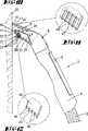
図11は吸い込み口の前方エッジの詳細斜視図であり、
図12は、取り外すことのできる吸い込み溝の吸い込み口の後方エッジの詳細斜視図であり、
図13は作業位置にある真空クリーナ・アタッチメントの別な実施例を示す部分断面側面図であり、
図14は別の構成をした吸い込み口の後方エッジの詳細斜視図であり、
図15は洗浄対象面から傾けて離した位置の図13による真空クリーナ・アタッチメントを示し、
図16は別の実施例を示す図9に対応の図であり、
図17は図16の線XVII-XVIIによる断面であり、
図18は洗浄対象面に載っている密閉リップの内側を示した拡大詳細図であり、図19は図18の線XIX-XIXによる断面斜視図であり、
図20は図4による別な実施例を示す詳細図であり、
図21は洗浄面から洗浄部材を移動した後の、図20に対応した図であり、
図22は液体非浸透膜の下流に設けた安全部材を示す、図4の詳細図であり、
図23は別の安全部材の概略図であり、
図24は膜の下流に設けた安全弁のさらに別の構造を示し、
図25は液体をフィードバックするための装置の概略図であり、
図26は蓄積媒体の織物繊維の概略図であり、
図27は、液体アプリケータおよび毛細管蓄積部が吸い込み溝およびリップに対してバネとは反対の軸方向の移動が可能な、真空クリーナ・アタッチメントの別の実施例を示す平面図であり、
図28は液体アプリケータと毛細管蓄積部の最前部のラッチ位置を示す、図27による真空クリーナ・アタッチメントの側面図であり、
図29は最後部位置を示す、図28に対応の図であり、
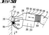
図30はラッチしてない位置であり、そこでは洗浄面に鋭角で真空クリーナ・アタッチメントが傾いている間、液体アプリケータと毛細管蓄積部がリップに対して軸方向に自由に移動可能である、図28に対応の図であり、
図31は洗浄面に対して真空クリーナ・アタッチメントの角度のあるアライメントについて示す、図30に対応の図であり、
図32は開いた位置にある別の安全部材の概略図であり、
図33は閉じた位置を示す図32に対応の図である。
図1に示すのは、吸い込みホース2を経て真空クリーナ3に接続させた真空クリーナ・アタッチメントである。真空クリーナ・アタッチメント1はハンドル4に設けられ、ハンドル4は吸い込みホース2の端に接続している。ハンドル4への真空クリーナ・アタッチメント1の固定は詳細を示してないが接合を介して行われる。真空クリーナ3を切り換えるために、オン/オフ・スイッチ5をハンドル4に設ける。
真空クリーナ・アタッチメント1は2つのハウジング部分から構成する。第一ハウジング部は接続ハウジング6であり、真空クリーナ3のハンドル4に接続可能である。接続端と反対側で接続ハウジング6にU字形のキャリア7が設けられ、作業ホルダ8として形成した第二ハウジング部を回転可能に取り付ける。
接続ハウジング6は端部にキャリア7を有する約45°の角度の笠形構造である。キャリア7のU字形脚部9は笠により形成される表面と約90°の角度で並べられ、キャリア7は両側で接続ハウジング6より突出しており、接続ハウジング6の本体の軸に対して直角に伸びている。その自由端付近では、U字形脚部9は軸受けピン10を有し、そのピンは作業ホルダ8のハウジングに係合している。
作業ホルダ8は断面形状が矩形である。図3、図4による基本位置では、作業ホルダ8はその下側11が接続ハウジング6の笠形表面12に平行で、かつその表面から間隔を取るように配置する。
接続ハウジング6の笠形表面12は、図3、図4に示すように下方に伸ばされて、この表面が接続ハウジング6の下側に突出する。キャリア7はこの突出付近に設ける。従って、作業ホルダ8も接続ハウジング6の下側より突出し、軸受けピン10が接続ハウジング6より突出している作業ホルダ8の端部付近に係合する。
接続ハウジング6から遠い側にある作業ホルダ8の前面13は、上側14に近い側、つまり笠形表面12から離れた側に近い側に吸い込み溝の吸い込み口15を有する。吸い込み口15は前面13の全幅を実質的に覆う広がりを持ち、スリット状に形成される。吸い込み口15の、上側14に面した前方エッジ16に、空気非浸透性のリップ17を全幅に渡って吸い込み溝に組み合わせる。前方エッジ16と反対に設けた後方エッジ18に吸い込み口15を縁取るための洗浄部材19を設ける。この洗浄部材19は洗浄用の不織布を装着したシール部材から成り、この不織布は洗浄対象の硬質面20と大きな機械的相互作用をおこなう。あるいは、シール部材も硬毛、フェルト等を設けた物を取り付けることも可能である。
作業方向Rにおいて洗浄部材18の上流に液体アプリケータ21を設ける。液体アプリケータ21は硬毛22の形の毛細管部材から成り、液体アプリケータ22は洗浄部材19、吸い込み口15、リップ17に平行の硬毛束の帯の形で作業ホルダ8の全幅を実質的に覆うように伸びている(図5参照)。
硬毛22は作業ホルダ8の前面13より突出し、リップ17の先端、洗浄部材19の前面、および硬毛束の帯により形成された端面が共通面E上にある。
硬毛22あるいは液体アプリケータ21は液体供給タンク23内に伸び、そのタンクは作業ホルダ8に長手方向に配列した壁24で境を作られている。この場合の硬毛22は後面25に近接し、間隔を取って伸びている。供給タンク23内に毛細管蓄積部26が設けられ、この蓄積部は詰め綿から成るのが望ましい。これは真空クリーナ・アタッチメント1がいかなる位置でも液体51を硬毛22に供給する役割を果たす。
前面13より突出した硬毛の先端のほつれを避けるため、硬毛22の周り、あるいは硬毛束の帯の周りを挟み込む硬毛ホルダ27が設けられる。
既に説明したように、作業ホルダ8の壁24が液体供給タンク23の境を作る。この壁によりさらに、吸い込み溝28が形成され、吸い込み口15に後続し、作業ホルダ8の後面25まで横に伸び、吸い込み溝の開口部29がその後面25の中央に設けられる。
作業ホルダ8の上側14で前面13に面する端部付近には、水を良く吸収する市販の材料で作られた残余水のワイパー30が設けられ、残余水が毛細管現象により吸い上げられる。このワイパーは作業方向Rでリップ17の下流に配置する。図3、図4に示すように、リップ状のワイパー30の先端は共通面から後退している。しかし、その先端は共通面Eに載るという構造も考えられる。
ヒンジを形成する軸受けピン10により作業ホルダ8は、キャリヤ7を介して接続ハウジング6に固定され、また、軸受けピンがリップ17と硬毛22または液体アプリケータ21との間の領域で、作業ホルダ8の前面13にできる限り近づくように位置するように配置してある。
軸受けピン10を中心にした作業ホルダ8の回転運動に追従できるフレキシブルな吸い込みホース31は、吸い込み溝の開口部29付近に開口している。この吸い込みホース31は吸い込み溝28と接続ハウジング6間の接続を形成する。そのためには、笠形表面12の上方に設けた開口部32をその表面12に設ける。
中空体として形成した接続ハウジング6は多孔性の発泡体や/あるいは活性炭の形のフィルタ33を有し、そのフィルタは蓄積媒体34と同じように設けられている。接続側には、液体蓄積部35が水非浸透性および洗浄剤非浸透性、空気非浸透性の膜36により境を作られて形成している。
毛細管現象を起こす特性を有する蓄積媒体34は、さらに詰め綿、海綿、粘土粒、紙、または多孔性の燒結材料、あるいは他のプロセスにより製造した多孔性材料等である。さらに、蓄積媒体34は膜36上にある液滴を毛細管現象により膜から媒体34内へ移動させるように構成する。
蓄積媒体34の吸い上げ容量は毛細管現象による光学的な充填率表示器37の助けでモニタを行う。このためには接続ハウジング6の上側には窓38を設け、その裏に蓄積媒体34内に突き出る毛細管センサ39を設置して液体の充填率に応じて色を変える。
あるいは、充填状態は負圧スイッチによって記録することもでき、この負圧は膜36の吸い込み側で記録される。この負圧は、水のフィルムが膜36の上で形成されると増大される。この場合、空気と液体の吸い込みは自動的に遮断され、真空クリーナ3のスイッチを切った後に真空クリーナ・アタッチメント1から液体が滴下するのを不可能とする。
洗浄対象面20への水あるいは洗浄剤の付与は硬毛22の毛細管現象により行われる。しかし、液体は硬毛22が表面と接している時だけ運ばれる。毛細管蓄積部26から液体を運び出すのは同様に毛細管現象による。
液体の付与と汚れ混じりの液体の吸い上げは一つの操作で行われる。洗浄媒体(望ましくは、水、アルコール、または界面活性剤)は硬毛22により洗浄対象面20に付与され、その含有量は一方において良好な洗浄効果を確実とし、他方において重力による流れを防ぐものである。本発明によれば、この量は洗浄面1平方メートルあたり約3から10グラムである。これは非常に少ない洗浄剤で広い面積の洗浄を可能とする。従って、液体供給タンク23も比較的小さな構造でよく、望ましくは30から150mlである。真空クリーナ・アタッチメント1の作業方向Rへの動きによって洗浄面20へ液体51が付与された後、洗浄部材19による汚れの除去が行われる。洗浄部材19は撥水性材料で作られるのが望ましい。さらに、この洗浄部材19はシール部材も有し、吸い込み溝28あるいは吸い込み口15の硬毛22に対する密閉を行う。リップ17により、洗浄剤と汚れの混じった液は洗浄面20から拭き取られ、吸い込み溝28の高速空気流により、汚れ混じりの液は吸い込み溝28とフレキシブルな吸い込みホース31を介して蓄積媒体34へ運ばれる(矢印a)。洗浄面20に残る水は拭き取り操作の終わりで必要な真空クリーナ・アタッチメント1の動きの結果、自動的に残余水ワイパー30により除去することができる。
吸い込み口15で生じる負圧は、液体供給タンク23から洗浄媒体の毛細管現象による移動を支援する目的で使用することができる。そのためには、移動させられる洗浄剤の量が、吸い込み口15と液体アプリケータ21あるいは硬毛22間で移動可能、あるいは開口部に局部的に設けたシール部材の設置により変化させることができる。
既に説明したように、汚れと洗浄媒体の混合液が、洗浄面20から接続した真空クリーナ3によりフィルタ33、あるいは蓄積媒体34へと吸い込まれる。ここで、汚れ、洗浄媒体、空気との分離が行われる(矢印b)。従って、汚れと洗浄媒体の混合液が分離される。濃縮物を除去され、同時に固体粒子を少量運ぶ空気流が真空クリーナ・アタッチメント1から流れる(矢印c)。
フィルタ33あるいは蓄積媒体34を通って流れる空気流を汚れと洗浄媒体の混合液の乾燥のために使用可能であり、これによって蓄積媒体34は少量の液体のみ蓄積するので寸法的に小型に作ることができる。少なくとも多孔性媒体を含む蓄積媒体34は濃縮相を保持する。しかし、蓄積媒体34の広大な表面積により多量の洗浄液が空気流との相互作用によって気体へ変わり、運ばれる。
汚れと洗浄媒体の混合液の確実な移動、および洗浄面20の残余なしの乾燥を行うために、本発明によれば、毎秒30から90mの速度の空気流を吸い込み領域に起こす。このためには、上記の位置での流速が毎秒3から15リットルの低速空気流でのみ実現できるように空気供給溝を構成することである。
さらに、蓄積媒体34に蓄積された液体を液体アプリケータ21または液体供給タンク23にフィードバックすることができる。これは毛細管現象による移動を介して行うことが可能である。しかし、この場合には、吸い込んだ空気に運ばれる汚れ粒子を少なくとも適切に浄化するように、フィードバックさせる液体を吸い込み空気の導入と液体蓄積部35の液体のフィードバックを互いに物理的に分離させる必要がある。吸い込み口15で発生した高い負圧をこの戻し移動に使用可能である。閉じたサイクルが形成され、広い面積の洗浄面が非常に少量の洗浄媒体で洗浄できる。真空クリーナ・アタッチメント1は、この場合、真空クリーナ・アタッチメント1のどの位置での使用にたいしても、吸い込み口15付近の負圧は蓄積媒体34の上流の負圧、さらにフィルタ33、使用済み水タンク35、毛細管媒体34での圧力降下よりも大きくなるように構成すべきである。
洗浄効果を増大させるためには、毛細管蓄積部26に蓄積した洗浄媒体に球状で、繊維のような粒子などの固体添加物を加える。
図5に示したように、液体アプリケータ21は硬毛の束の複数の帯として形成することが可能であり、これは近接して締め付けた個々の硬毛22から成る。別の構成が図6、図7に示されている。ここでは、硬毛束の帯は小分割されており、この小分割は硬毛束の連続帯が近接するように行われる。図6では、これは硬毛40の束のハニカム構造により実現し、図7では、これは硬毛41の束の三角形構造により得られる。
本発明の主題に関わる2つの実施例が図8から図15に示されている。その機能は前述の実施例と同一である。ここでは、吸い込み溝の吸い込み口のエッジの別な形状についてのみ示す。
初めに、図8から図12を参照にして、真空クリーナ・アタッチメント1が吸い込み溝の吸い込み口15を有し、その吸い込み口のエッジ42は液体アプリケータ21に面しており、取り外しできる。この吸い込み口のエッジ42は液体アプリケータ21と洗浄部材19の作業方向Rの下流に設けられており、例えば、吸い込み方向に移動可能である。そのためには、エッジ42は対応した形の溝状レシーバ43内に設けた帯のように形成されており、作業対象面の方向に開いている。さらに、圧縮バネ44がレシーバ43内に設けられており、エッジ42の自動的な外側への移動を行い、これによって、エッジ42は真空クリーナ・アタッチメント1の特定の当接角になるまで常に洗浄面20に接触している。洗浄面20の方向を指しているエッジの非接触端では、エッジ42が櫛のような構造をしている。そのためには、歯様の突起45が末端部に一体に成形して設け、近接した境を設けた吸い込み溝46とするために突起45の間に隙間を形成する(図12参照)。
この後方エッジ42の櫛構造は市販の撥水性プラスチックで作ることが望ましく、吸い込み口15のこの後方エッジ42は洗浄面20の洗浄時に汚れ混じりの洗浄液の良好な吸い上げを提供する。というのは、近接して境界を設けた吸い込み溝46の結果として空気流速度が上昇するからである。吸い込み口の先端エッジは、この場合には空気非浸透性リップ17で形成される。
洗浄作業を終了させる前に洗浄面20から残余水および汚れを除去するため、真空クリーナ・アタッチメント1は、液体アプリケータ21、洗浄部材19、リップ17が作用しないように洗浄面20から離すように傾ける。これにより、エッジ42は圧縮バネ44のバネ力によりレシーバ43から離脱し、吸い込み口15の後方エッジ48を形成し続け、エッジ42がその突起45により洗浄面20に係合する。吸い込み口15に対向するエッジが前方エッジ47により形成されている。この前方エッジ47も櫛形構造を有し、作業方向Rにおいてリップ17の後方でリップ17に設けられる。
真空クリーナ・アタッチメント1を傾けた結果、液体アプリケータ21を洗浄面20から持ち上げることになり、初めに液体の供給が中断される。この場合、洗浄面より離れたエッジ42と、櫛形構造の前方エッジ47を有する吸い込み口15は洗浄面20に係合し続ける。こうして、前方エッジ47と後方エッジ48の両方によって近接して境界を設けた吸い込み溝49、46が作られる。この構造により、空気は高速で境界を設けた吸い込み溝49、46を通って吸い込まれ、洗浄面20に残った水が霧化される。この残存水の霧化は前方エッジ47と後方エッジ48の櫛形構造の空気流に対する鋭いエッジと下流への直接的な偏向により、さらに改善される。残存水の霧化の後、真空クリーナ・アタッチメント1は洗浄面20から取り除くことになる。
図13から図15には別の実施例が示されている。これは前述の実施例とは異なり、櫛形前方エッジ47を有するリップ17が作業ホルダ8の残りの部分に対して回動可能なように取り付けてあり、吸い込み口15のエッジ42あるいは後方エッジ48は固定部材とされ、近接した境界を設けた吸い込み溝50を形成するため、洗浄対象面20の方向に向いた鋤形構造の末端エッジを有する。
前方エッジ47と後方エッジ48の櫛形構造と鋤形構造は前述した実施例でのように、通常の作業位置では効果を発揮しない(図13参照)。真空クリーナ・アタッチメント1を図15の位置のように傾けて離す時に、櫛形構造前方エッジ47と鋤形構造の後方エッジ48だけが洗浄対象面20と接し、これにより前方エッジ47と後方エッジ48の付近の近接して境界を設けた吸い込み溝により残った水の霧化がここで再度行われる。
図9による真空クリーナ・アタッチメント1の別な実施例が図16に示されている。毛細管蓄積部26から出る硬毛22は洗浄面20に対して約60°の角αを有するように設けられている。しかし、αの角度は約30°から60°も考えられる。
この場合、硬毛22の配置は洗浄面20上で真空クリーナ・アタッチメント1を引きずる時に、ほぼ全硬毛表面で洗浄面20に接するので、作業方向Rと逆方向に少し曲がることで、例えば、洗浄面20の製造誤差や不均一にたいする補償をするという利点がある。
さらに、吸い込み口15の別な形状が考えられる。ここでは、吸い込み領域は吸い込み口15から生まれた刺状の溝の形にした複数の吸い込み溝小部分52として形成されている。これらの吸い込み溝小部分52は、装置の全幅に渡り、あるいは吸い込み口15の長手の全領域に渡り均一に配置されており、断面がU字形状が望ましい。吸い込み溝小部分52は前面13の固定されてない突出端付近(底部を形成)に形成されており、複数のU字状の溝境界が装置のハウジング側に設けられることになる。
さらに、吸い込み溝小部分52はリップ17で境を付けられて、刺状の溝が作られる。
この構造は優れた吸い込みを提供する。吸い込み溝小部分52は吸い込み溝28へ向けてある角度で進むように斜めに設けることが、更に望ましい。角度をつけた吸い込み溝小部分52は、図17にその断面が示されている。吸い込み溝小部分52はその傾斜が主軸x−xに対称に設けられ、その主軸は同時に吸い込み溝28の中央軸を形成する。吸い込み溝小部分52の傾きは、吸い込み溝小部分52の中央軸yが吸い込み溝28の主軸xと交差し、望ましくは、この交差が真空クリーナ・アタッチメントの本体内で行われるように選択する。図示の実施例では、吸い込み溝小部分52の軸yは主軸xと約30°の角度を持つ。しかし、この角度は30°から60°が可能である。
洗浄操作において、吸い込み口15から始まる吸い込み溝小部分52の構造は、リップ17の付近まで伸び、拭き取りゴムとして形成され、拭き取りゴムあるいはリップ17の瞬時の乾燥が行われるという利点を有し、その結果、真空クリーナ・アタッチメント1のリップ領域が、例えば窓ガラスに再度使われる時に水の筋がつくのを防止する。さらに、この種の構造は小さな空気流でも断面が小さく、吸い込み溝小部分52内での高速空気流による吸い込みによって水の除去を改善する。また、吸い込み溝小部分52の斜めの溝は吸い込み溝28の方向へ空気流を整える効果がある。
例えば、窓枠の縁でリップ17を移動する操作は、リップ17が曲げにくいのでかなり難しい。その結果、洗浄液は洗浄面から完全に除去できるとは限らない。従って、窓ガラスのこれらの位置で筋ができる。
本発明によれば、この問題はリップ17を二重リップとして形成することで解決した。
図16に示す様に、リップ17は吸い込み溝28の境を成すハウジング壁53の延長部として形成し、またリップ17は吸い込み口15と吸い込み溝小部分52境を形成する。
作業方向Rで見ると、外側の第二リップ54がリップ17の下流に設けられ、望ましくは、内側のリップ17より柔らかい材料で作られる。このケースでは、外部リップ54は作業操作時に洗浄面20から離れる位置に設ける構成である(図16参照)。従って、通常の洗浄操作では、この第二リップ54は洗浄面20に接触しない。真空クリーナ・アタッチメント1を除去する操作では、前述のようにアタッチメントに角度をつけ、第二リップ54が洗浄面20と接し、それにより、例えば窓枠付近では窓ガラスをさらに拭き取る。
洗浄面20に残っている残留水の量を減らすために、さらに改良を加えるなら、空気非浸透性のリップ17の洗浄面20との接触する部分に複数の小さな溝55を設ける。この小さな溝は液体アプリケータ21に面するリップ17の側、従って吸い込み口15に設け、リップ17の幅方向に延伸している。これらの小さな溝55は平面図では鋭角な三角形状で、吸い込み溝の開口部29の付近に近接して設けられている。
小さな溝55は、その先端が洗浄面20と接触する領域に近くなるように配置され、それらの先端が吸い込み溝28を貫く主軸xから離れた方を向く。断面形状では、これらの小さな溝55は弓形であり、主軸x方向において先端から深さが増大する(図19の斜視図参照)。
この構成により、特に、小さな溝55の形状により、異なった毛細管圧が得られ、残留水56が圧力傾斜によって吸い込み溝28の方へ移動させられ、空気流により運ばれる。
図4で示した真空クリーナ・アタッチメント1の作業ホルダ8は、別の実施例として図20と図21に示されている。洗浄部材19が洗浄面20に作用する通常位置(図20参照)から後方の吸い込み口15の断面が拡大する位置(図21)に移動可能なように設けられている。このためには、例えば、洗浄部材19はスロット57内のピンにより取り付けられ、図示しないハンドルでユーザにより移動させることができる。この場合、後退位置の洗浄部材19を収納できるチャンバ58を設ける。
この構造により、落ちにくい汚れの場合や、洗浄面20に付与する洗浄剤の量が増大する他のケースにおいて、液体アプリケータ21の洗浄媒体流量を増大するために吸い込み溝28内の負圧を使用することが可能である。洗浄部材19のチャンバ58への移動により、吸い込み口15と液体アプリケータ21間の空間的分離が生まれ、液体アプリケータにおいて外気に対して負圧が優勢となり、その結果、多量の洗浄液が毛細管アプリケータを通して送られる。
洗浄剤の流量を増大させるために移動可能に設ける装置の別の部材によって、空間的分離を行うことも考えられる。
ユーザに対する危険、例えば、電気の短絡などによるいかなる危険も与えないために、洗浄液51は吸い込みに必要な真空クリーナ3の作動部品に濃縮状態で通してはならない。本発明によれば、これは真空クリーナ・アタッチメント1の適切な位置、例えば、真空クリーナ3のインターフェースのすぐ上流に湿度センサを設けて、濃縮洗浄液との接触により供給電流を直ぐに遮断することによって実現可能である。この種の湿度センサは市販品でかまわない。
別の構成では、液体非浸透膜36に代わって、あるいは、補足的部材として、濃縮洗浄液を捕捉する部材の使用が考えられる。これは図22に一実施例として示してある。
ここでは、安全部材59が流れの方向で膜36の下流に設けられ、真空クリーナ3へのインターフェース付近で直接行う。
安全部材59は2個の多孔性壁60間に埋設した膨張物質61を有する。
安全部材59は液体蓄積部35の一部であり、膨張物質61が液体を吸収すると体積を増大させるように設けられている。濃縮液の捕捉は化学的あるいは化学物理的に行うことができる。既に説明したように、望ましい実施例では、水の捕捉媒体61が多孔性の穴の内に埋設されている。水捕捉媒体は、例えば、ポリアクリレートのような高分子工業製品であるが、じゃがいもの澱粉のような天然作物も考えられる。
膨張物質61を有する安全部材59の充満により、分流路が設けられる。つまり、この水捕捉媒体は濃縮した水を吸うために形成した膨張物質の大きな表面による安全装置が、ユーザにたいする危険を回避するために設けられる。通過するどのような水分も水捕捉媒体により吸収され、この水捕捉媒体は濃縮液との接触でその状態を膨張して変え、大きな圧力降下が膨張物質61の位置で生じて、水量の増大で空気流は最終的に行き詰まる。この手段により、真空クリーナ3への濃縮物質の移動が防止される。
従って、これが液体蓄積部35の特定充填率に応じた吸い込みを制御可能にする装置を作る。本発明の主題による別の実施例では、水捕捉媒体、特に膨張物質61の体積の増大は、濃縮水分と混ざった空気流を水捕捉物質から成る壁の間の隙間を通すように使用するのが有利である。
このタイプの構造は図23に示されている。吸い込み溝28の領域に、吸い込み溝を閉じる芯部材62を設け、この芯部材は、例えば閉じた多孔性の気泡体のようなもので作られ、方向を変える分流路63のみ残す。流路63の長い方向変化は比較的大きな表面を作るために役立ち、分流路63の壁が部分的あるいは全面的に膨張物質61を含む。濃縮液がその分流路の付近に生じたら、水捕捉媒体(膨張物質61)の体積の増大により流路63の幅を減少し、空気流を完全に遮断し、その結果、ユーザにたいする危険は回避される。
この種の構造は別の安全部材として水非浸透膜36の下流に接続することもできる。
膜36での液体保有圧を縮小するため、流れ方向で膜36の下流に安全弁64が設けられる(図24参照)。このためには、圧力バランス溝が設けられ、その流出方向で示された一方の端部は膜36の上流に接続し、もう一方の端部は吸い込み溝28の内部に設けた圧力室66に接続されている。この圧力室の内部に弾性膜67を収納し、先端に装着した密閉三角錐部材69を有するプランジャ68が弾性膜67に固定されている。この三角錐部材は、液体蓄積部35の水非浸透膜36の方向に作用する。この場合、密閉三角錐部材69はゴムで作られる構造が望ましい。
流れの方向において、水非浸透膜36の下流に該膜に同軸に軸方向の開口部71を有する阻止壁70が設けられる。
圧力室66と密閉三角錐部材69の間に引っ張りバネ72を設け、プランジャ68を取り囲み、軸方向開口部71の開口位置で、密閉三角錐部材69をプランジャ68と共に保持する。
膜36に近い液体蓄積部35の付近に圧力バランス室65の入口が、水非浸透膜73により閉じられることが望ましい。さらに、圧力室66は圧力バランス溝65の入口領域に対向して設けた弾性膜67の付近に圧力バランス開口部74を有する。この構造により、弾性膜67は液体非浸透膜36の上流より高い圧力により片側に負荷を受け、吸い込み溝28の圧力を反対側に受ける。
通常の操作では、つまり、液体蓄積部35の低あるいは中間充填率では、圧力差は低く、引っ張りバネ72の力は開口位置に密閉三角錐部材69を保持する。しかし、液体蓄積部35の充填率が最大に達するやいなや、水非浸透膜上に水のフィルムができるので圧力差は増大する。この圧力差により、軸方向開口部71の方向でこの開口部71の完全な閉鎖まで密閉三角錐部材69の移動が行われ、空気流が遮断されて、水非浸透膜36が守られる(図24の点線で示されている)。
この閉鎖位置で、さらに、密閉三角錐部材69の前面は水非浸透膜36を守るために水非浸透膜36を支持する役目を行う。
このタイプの構造は膜が安全弁無しのものより低い液体保有圧力に耐えればよく、上記の調節可能な圧力差により、安全弁64は閉じたり膜36を助けるという利点を有する。この構造により、濃縮した液体を吸い上げるのに適さないものを含め、ほぼ全部の市販真空クリーナにこのアタッチメント1を使用することが可能となる。
安全弁64に機械的に接続した単純な表示装置により、ユーザに対して液体蓄積部35が最大レベルに充填されたこと、および交換あるいは再生すべきであることを示すことができる。このために、例えば、図24に示したように、指針75を密閉三角錐部材69に、あるいはプランジャ68に設けて、指針75の位置が小さな窓76を通して外部からユーザが観察できるようにする。
既に述べたように、濾過済み液を液体蓄積部35から毛細管蓄積部26にフィードバックさせることが可能である。一構成例を図25に示す。
この目的のために、図20で既に説明した真空クリーナ・アタッチメント1の実施例に、フレキシブル・ホースの形の切り換え可能な流路接続部77を設ける。この流路接続部は、送風装置側に面した、あるいは液体蓄積部35から離れて面した膜の側と、毛細管蓄積部26の間を接続する。膜の形でも可能な水非浸透性シール78を接続部77から毛細管蓄積部26への入口付近に設けることが望ましい。さらに、空気フィルタ79を接続部77から吸い込み溝28への接続位置に設けることもできる。
また、液体戻し接続部80を毛細管蓄積部26と液体蓄積部35の間に設ける。この接続部もフレキシブルなホースなどである。
この構成により、濾過液は液体蓄積部35から吸い出され毛細管蓄積部26へ戻すことが可能となる。従って、液体蓄積部35にある液体で毛細管蓄積部26を再度満たすために、別の手段は必要としない。このようにフィードバックするためには、接続部77と80の切り換えを、例えば、リリース・スイッチ81、82をユーザが作動させて行う必要があるだけである。リリース・スイッチ81、82は図25には概略でのみ示してある。
接続部77と80が開放されると、毛細管蓄積部26は液体蓄積部35よりも大きな負圧を受けることになる。液体蓄積部35にあり、濾過された液体は戻り接続部80を経て毛細管蓄積部26へ吸い戻され、空気流路は流路接続部77を経て通常の作業位置とは偏向させられる。
前述のごとく、接続部の開放はリリース・スイッチにより行うことができる。しかし、作業ホルダ8の領域に押しボタン・スイッチを設け、洗浄面20から持ち上げる時に、流路接続部77および戻り接続部80を開放することも考えられる。従って、真空クリーナ・アタッチメント1が洗浄面にある時、対応の遮断部材は流路接続を閉じる位置にある。
液体蓄積部35から毛細管蓄積部26への液体のフィードバックは、液体蓄積部35と毛細管蓄積部26の間に、移動のために必要な圧力差を与える適切な毛細管現象による移動ラインを設けて行うことも可能である。この場合には、ユーザが装置をオフにした時にのみ移動が行われるのが望ましい。こうした構成では、逆止め弁などを毛細管移動ラインの付近に挿入するのが有利である。
図26に拡大して概略示すように、吸い上げた水を中間的に蓄積したり、蒸発する原理を表している。一構成例では、蓄積媒体34は織布繊維83から構成するのが望ましく、織布繊維83は一方では吸い上げた液体51を微小な孔84内に溜め、毛細管現象により移動させ、微細なスリット85あるいは微細な開口部86を介して表面87に送り、その表面から迅速に蒸発させる。この構成により、供給される空気流の相対湿度は露点より下を維持し、電気回路の短絡などの危険を回避できる。
図27から図31には、真空クリーナ・アタッチメント1の別な構成が示されている。ここで重要な事は液体供給タンク23と毛細管蓄積部26を有する液体アプリケータ21がリップ17や吸い込み口15に対して軸方向に移動可能な事である。
リップ17、吸い込み口15、吸い込み溝28等は、互いに接続された装置部品として形成されており、他の実施例でのように、吸い込み溝28は接続ハウジング6に設けた液体蓄積部35内へ開いている。吸い込み溝28の長軸に対して、接続ハウジング6はこの溝にある角度で曲げられている。また、吸い込み溝28は接続ハウジング6と、リップ17と吸い込み口15を収納する領域との間の構造的な接続を形成する。この露出した領域において、吸い込み溝28とその外壁は断面が円形として形成する。
毛細管蓄積部26を収納する液体供給タンク23は下側に位置しており、つまり、作業方向Rの吸い込み口15の前に設けられており、前述した実施例でのように、液体アプリケータ21は液体供給タンク23の前側に設けられ、洗浄面20に面している。図27による平面図では、液体供給タンク23が吸い込み溝28を越えて、その両側に突き出しており、吸い込み溝28とその外壁を囲むスリーブ状の接続部材90を有している。このスリーブ状の接続部材90を経て、主に液体アプリケータ21と毛細管蓄積部26から成る装置部材は、主としてリップ17と吸い込み溝28を有する第二装置部材に保持されている。この構成により、毛細管蓄積部23と共に液体アプリケータ21は吸い込み溝28に沿って軸方向に移動可能となる。
接続部材90は作動ノブ91を有しており、これにより図28に示した最前方位置および図29に示した最後方位置に固定できる。
この作動ノブ91を経て、必要に応じ、ラッチ・ピン92等を接続部材90の対応する形状のラッチ窪み93に導入可能となる。全体のラッチ装置は図では概略で示されている。
接続部材90と、吸い込み溝28から接続ハウジング6への中間部分に成形されたショルダとの間に、吸い込み溝28と同心円に設けたバネ94が配置され、このバネは液体アプリケータ21を有するハウジング部材および毛細管蓄積部26を最前方位置の方向へバネ附勢する作用を有する。従って、最後方位置の方向への移動はこのバネ力に反して行われる。
さらに、洗浄部材19は洗浄布95で形成され、洗浄布は微細な非織布が望ましく、液体アプリケータ21の上に張られる。この洗浄布95は、液体アプリケータ21と吸い込み口15の間の一端と、吸い込み口15から離れた側に面する液体アプリケータ21の側の他端で、例えば締め付けによりハウジングに固定され、この保持状態は概略でのみ示されている。
図28から分かるように、他端がハウジングの下側に固定される構造が望ましい。さらに望ましいのは、洗浄布95が例えば清掃のために交換可能な構造である。
作業対象面20の洗浄の時に、洗浄布95は液体アプリケータ21により裏側から湿らせる。
さらに、真空クリーナ・アタッチメント1は頑固な汚れを除去するために、スクレーパ・エッジ(図示せず)を有することも可能である。
初めの作業工程では、例えば洗浄面20の大きな汚れを溶かしたり柔らかくするため、毛細管蓄積部26を伴った液体アプリケータ21を最前方位置に移動させてラッチにより固定する。この位置は図28に示されている。液体アプリケータ21および洗浄布95の形の洗浄部材19がリップ17の面より前に位置し、リップ17が付与液を拭き取ることなく、裏側を湿らせた洗浄布95が洗浄面20に作用することができる。これは、例えば、吸い込み無しで洗浄面20を洗浄するために分離加湿を可能とする。
図29によるハード・エッジ作用を行うために、毛細管蓄積部26を伴った液体アプリケータ21を最後方位置に移動させて、ラッチにより固定する。この場合、液体アプリケータ21および洗浄布95はリップ17の面より後方に設置されるように並べられ、洗浄面20がリップ17のみと接触する。これは、例えば、近づくのが困難な領域の残留水分を拭き取るため、あるいは雨の後のガラス面を乾かすためのものである。
最前方位置および最後方位置を決めるラッチ手段は本発明では完全に省く事も可能であり、その結果、液体アプリケータ21および毛細管蓄積部26を収納する装置部材は吸い込み溝28やその外壁から自由に取り外すことができる。これは真空クリーナ・アタッチメント1の通常の利用において有利である。つまり、この構造により液体アプリケータ21、そのアプリケータ上に張った洗浄布95、およびリップ17はそれぞれ、洗浄面20に常に接し、矢印Rの方向の作業の時でも、真空クリーナ・アタッチメント1は傾きを大きくしたり、傾きを少なくしたりすることも可能である。洗浄布95と液体アプリケータ21は、バネ94によるバネ附勢の結果として、常に自動的に洗浄面20との接触位置を確実なものとする。図30と図31は洗浄面20と真空クリーナ・アタッチメント1の2つの異なった角度位置を示し、図30ではアタッチメント1が約80°で図31では約70°の角度を有する。本発明による構成の結果として、約30から50°の角度域、望ましくは40°が与えられており、この範囲ではリップ17と洗浄布95との洗浄面20との接触が常にある。
図32と図33には別の実施例が示されており、液体蓄積部35の特定充填率に基づき吸い込みを制御可能に引き起こすための安全部材95を含む。天然の海綿のような海綿形状の阻止部材96を液体蓄積部35の下流に設けた構成が示されている。図では、阻止部材は多孔気泡体の例が示されている。この海綿状阻止部材96は吸い込み方向から見て、液体蓄積部35の後端と直接接触している。
阻止部材96は液体蓄積部35から遠い側に弁64により作用させられる。この弁は密閉三角錐部材97を有し、接続ハウジングの側の密閉壁98と相互作用を行う。密閉壁98の付近に軸開口部99が設けられ、制御部材100が貫通しており、その制御部材100を介して密閉三角錐部材97が阻止部材96に支持されている。さらに、密閉三角錐部材97は圧縮バネ101によって阻止部材96の方向へ作用する。
図32は、弁64が開放位置に保持された状態を示す。弁64はこの場合、阻止部材96の制御部材100を介して支持され、吸い込みの通過領域が密閉壁98と密閉三角錐部材97間に形成されている。液体蓄積部35が最大充填レベルに達すると、海綿状の阻止部材が水分により作動し、阻止部材は軟化して圧縮可能になる。この水分依存の圧縮可能性により、弁64はバネの附勢によって閉位置に移動する。この位置は図33に示されている。制御部材100は、制御部材上の密閉三角錐部材97が密閉状態で密閉壁98に係合して、吸い込みを遮断するように阻止部材96を圧縮する。
液体蓄積部35が空になったら、阻止部材96は徐々に乾くので自動的に圧縮から復元し、再度固くなり、弁64を図32の初期位置に戻す。
安全部材95の上記した構造は、液体を吸収し、所定の充填率に達したら自動的に閉じることができる他の容器も考えられる。
以上説明した全ての特徴は本発明に直接関係するものである。本出願の記載において、添付の優先権証明書(元出願の複写)の記述内容もここに含まれ、これらの文書の特徴は本願の請求項に含まれる。The present invention relates to a wet cleaning vacuum cleaner attachment for a surface, particularly a vertical surface, having a liquid applicator, a suction groove having a suction port, and a cleaning member.
In addition to conventional vacuum cleaners, devices are also known that use liquids, in particular cleaning liquids, that can be sucked back in one operation. However, such devices are only suitable for cleaning on hard floors. Wet cleaning performed in one operation is not known for cleaning hard surfaces such as windowpanes. In order to clean this type of surface, an apparatus is provided having a separate tank of fresh water and a tank of dirty water. In this case, washing including drying is performed in several steps. First, in the first operation, the cleaning liquid is sprayed onto a hard surface such as a window glass by a pump and a spray nozzle. In the second step, the cleaning solution is diffused using a special sponge. Following this, in the final step, the cleaning liquid containing dirt is sucked up using a suction nozzle connected to the blower by a suction hose. The disadvantage of this configuration is that it cannot be operated continuously. This is particularly associated with the drawbacks associated with the care of multiple walls.
The object of the present invention is that even if the device is used in a vertical plane, or when the normal vector of the surface has a non-annihilation component opposite to the gravity vector, such as an inclined skylight or ceiling, It is to provide an improved attachment of a vacuum cleaner for surface wet cleaning so that cleaning and suction of cleaning liquid can be performed in one operation.
The object is achieved by means of the invention as defined in
Each claim subsequent to claim 1 shows an embodiment of the present invention.
On the basis of this configuration, a vacuum cleaner attachment is provided that can work continuously on various surfaces, especially vertical surfaces. For the purpose of continuous operation, a liquid applicator is provided for the continuous supply of liquid, and a suction groove suction port is provided downstream from the liquid application direction of the liquid applicator, within the range of the liquid applicator or the liquid applicator. This is achieved by providing a cleaning member between the suction groove and the suction groove. By this means, even a particularly hard vertical surface such as a window glass surface can be cleaned by a single operation. As a result of the liquid applicator being configured to continuously supply liquid, the apparatus of the present invention can be used regardless of any tilt of the surface to be cleaned, i.e., in the case of a vertical surface. In addition, overhead work is possible. When working on the surface, the liquid is continuously conveyed to the surface to be cleaned by the liquid applicator, the surface is first cleaned by the cleaning member, and by one operation of the device in one processing direction in the area of the suction groove, The dirty cleaning liquid is sucked in directly and continuously.
In this case, a structure in which the liquid applicator is supplied with a liquid by capillary action is desirable. As a result of such a structure, it is possible to omit an operating member for applying the cleaning liquid to the surface to be cleaned. The actuating member is a pump, a spray nozzle, or the like, and such a structure has a defect that uniform humidification of the surface to be cleaned cannot be realized as a result of spraying the cleaning liquid. Further, in this case, when the window is cleaned, the cleaning liquid is incidentally and forcefully sprayed on a portion other than the cleaning target such as a window frame. In the case of the known technique, the cleaning liquid may drop or flow on a vertical surface or inclined surface such as a window glass surface. In the case of the present invention, these problems are remedied in an optimal manner by the movement of the cleaning liquid by capillary action. The uniform application of the cleaning agent to the surface to be cleaned is performed without a pump or other electromechanical or electrical means. The cleaning medium, preferably water, alcohols, or surfactants, is applied to the surface to be cleaned by a liquid applicator, one that ensures a good cleaning effect and the other that can be prevented from flowing due to gravity. To be granted. According to the invention, the amount required in this case is 2 to 10 g of water per square meter of hard surface. Thus, the present invention can reliably clean large hard surfaces with a very small amount of cleaning media.
In another embodiment of the present inventive subject matter, the liquid applicator is partitioned into small structures for the application area of the cleaning liquid. This segmentation is preferably done so as to approximate a length that substantially covers the full width of the continuous liquid applicator, preferably the vacuum cleaner attachment. This small structure can be formed, for example, in the form of a honeycomb or a triangle, or another rectangle or circle. In this case, the liquid applicator is preferably composed of a bundle of bristles suitable for a specific supply of liquid. The bundle of bristles can be formed continuously to cover substantially the entire width of the plurality of bundles of bristles, i.e. the vacuum cleaner attachment. However, as already described, small structures in which the bristle bundles are arranged in a honeycomb shape or a triangular shape are also conceivable. Application of the cleaning agent to the surface to be cleaned is performed by a capillary gap in a bundle of hard hairs. In this case, however, the cleaning agent is delivered only when the bristles are in contact with, for example, the window glass surface. If the bristle protrudes from the lower side of the vacuum cleaner attachment, the bristle can be supplied to the portion of the bristle that is tightened by the bristle holder for preventing fraying of the bristle. It has proved to be particularly advantageous as a bundle of bristles to be composed of bristles having an angle of about 30 to 60 degrees with the surface to be cleaned. What is obtained as a result of the arrangement of the bristles oblique to the surface to be cleaned is that the bristles bend slightly in the lateral direction to bring the entire bristles into contact with the surface to be cleaned, thereby Compensation for manufacturing errors and non-uniformity of the surface to be cleaned.
The supply to the liquid applicator, particularly the bundle of bristles, is performed in a configuration in which the liquid applicator is in the capillary accumulation part and is supplied from the accumulation part by capillary action. As already explained, the present invention can reliably clean large areas using very small amounts of cleaning media. Accordingly, it is possible to store a necessary amount of the cleaning medium in a relatively small tank such as a capillary accumulation unit. In this case, it is desirable that the capillary storage unit can hold 30 to 150 ml of cleaning liquid in advance. In order to ensure the movement of the cleaning medium by capillary action so that it can function in any position, the capillary reservoir will at least partially move the moving medium that is always in contact with the cleaning medium, i.e. the bristles of the liquid applicator. I have. According to the present invention, the moving medium should be configured in consideration of its moisture retention characteristics and geometry so that a desired amount of movement from the capillary accumulation part to the surface to be cleaned can be achieved by capillary action. According to the present invention, the required structure can be obtained by selecting appropriate materials, their surface treatments, geometric arrangements and the like. In this case, it is desirable that the capillary accumulating portion is made of stuffed cotton and the stuffed cotton can continuously supply the cleaning liquid to the bundle of hard hairs by the capillary phenomenon at any position of the vacuum cleaner attachment. According to the present invention, it is also possible to make the suction port of the suction groove into a slit shape. It is desirable to connect the vacuum cleaner attachment to a commercially available vacuum cleaner.
To clean hard surfaces, especially vertical surfaces, the vacuum cleaner can be switched on and then the hard surfaces can be cleaned. During the cleaning operation, the cleaning liquid is applied to the surface to be cleaned by the applicator, and is guided again through the suction groove by the same operation. In this case, in a preferred form, the inlet has a width corresponding to the width of the liquid applicator, in particular the band width of the bristles. In order to surely move the cleaning liquid mixed with dirt and to perform drying in a state in which no cleaning liquid remains on the surface to be cleaned, in the present invention, an air flow at a speed of 30 to 90 m per second is generated in the suction area. For this reason, the air supply groove is configured so that the flow velocity at the above position can be realized only with a low-speed air flow of 3 to 15 liters per second, preferably 1.5 to 7 liters. According to the present invention, the negative pressure generated at the suction port of the suction groove can be used to help carry out the cleaning medium from the capillary accumulation part by capillary action. As described above, the suction groove or suction port is disposed downstream in the working direction with respect to the liquid applicator. In order to clean the surface to be cleaned in two directions perpendicular to the long edge of the vacuum cleaner attachment, the attachment is formed symmetrically with respect to the liquid applicator, in particular the band of the bristle bundle, ie the second suction groove It is possible to provide a suction port. In order to ensure ideal cleaning of the surface, a cleaning member is provided to form the end of the inlet.
For this reason, the cleaning member is formed in the vicinity between the liquid applicator and the suction groove. In order to assist when the cleaning medium is moved by capillary action from the capillary accumulation part due to the negative pressure generated at the suction port of the suction groove, it is conceivable to provide a movable opening or a partial opening in the cleaning member. . The cleaning member is preferably formed of a sealing member having a non-woven cloth fitted therein. The sealing member has a large mechanical interaction with the surface to be cleaned. Alternatively, the cleaning member can be constituted by a sealing member having inlayed bristles, felt, or the like. In this case, however, it is desirable to use a water-repellent material. It is desirable that the cleaning non-woven cloth or the like is configured to apply a high peeling force to the dirt to be removed. Furthermore, the sealing member of the cleaning member seals the suction groove with respect to the liquid applicator or the bristles. The supply of air is performed only in the vicinity of the cleaning non-woven cloth and the like, and only in the small gap in the vicinity of the cleaning non-woven cloth and the like that can be formed during the operation between the surface to be cleaned and the seal member. This will increase the air flow velocity in this region. In order to form the suction space, it is conceivable that the end processing of the suction port of the suction groove provided downstream in the processing direction is performed by a lip member that does not allow air to permeate. The lip member can be formed as a rubber lip member that removes the mixture of the cleaning agent and the dirt from the surface during operation on the surface to be cleaned. As a result of the high velocity air flow in the suction channel, the removed mixture moves through the suction port, which acts to prevent dripping of sewage from the vacuum cleaner attachment after the vacuum cleaner is switched off.
Furthermore, the suction port of the suction groove can be composed of a plurality of individual suction grooves. As described above, one configuration example is a removal rubber continuously placed on the surface to be cleaned in the shape of a lip member that does not allow air to permeate, which simultaneously limits the suction space on the side facing the cleaning member. Form. According to the present invention, the entire width of the nozzle is covered from the main suction groove provided inside the nozzle, and a small stab groove as a small portion of the suction groove extends directly from the main suction groove to the removed rubber member or the air non-permeable lip member. ing. This stab-like groove has the effect of drying the lip member immediately, and for example, when the lip member is newly replaced on a window glass, this means prevents water streaks. Further, the suction of this shape allows a very high speed air flow in a small portion of the suction groove due to the small cross section, and as a result, the water removal rate can be improved by sucking with a small amount of air. In this case, it can be seen that it is particularly effective to partially border the small portion of the suction groove with the lip member. For example, the stab groove can be formed in the shape of a comb groove having an open end near the bottom of the nozzle housing. In order to form a stab groove, the stab groove borders one side of the lip member. Further, according to the present invention, the small portion of the suction groove is configured to run obliquely so as to advance at an angle toward the suction groove. This is advantageous from the point of view of the flow mechanism, especially if the small axis of the suction groove intersects at a point on the central axis of the suction groove. In this case, the intersection may be near the suction port of the suction groove.
However, a structure in which the intersection is provided near the suction groove and outside the suction port is desirable. The problem here is, for example, the operation of lowering the rubber lip member, particularly the above-mentioned air-impermeable lip member, onto the window glass surface at the end of the window frame. This is because the rubber lip member is partially bent at the window frame, and as a result, the cleaning liquid is not completely removed at the periphery of the glass surface. And streaks of sewage are made at those positions. According to the present invention, this problem is solved by making the lip member a double lip member.
That is, the first lip and the second lip continue in the working direction. In this case, the outer lip is made of a material softer than the inner lip. Moreover, it is desirable that the rubber lip member is very flexible, and at the downstream position thereof, for example, the rubber lip member can be placed on the window glass during the removal operation near the window frame. In this case, the outer lip prevents the first lip from being placed on the surface to be cleaned, particularly the window glass, in a normal wiping operation, and wipes the window glass only when the window frame is bent downward of the attachment device, for example. Attach to the first lip. This is accomplished by forming the outer lip so that it is at a considerable distance from the target surface so that it does not contact the surface to be cleaned during normal cleaning operations. In order to reduce or eliminate the amount of cleaning liquid remaining on the surface to be cleaned, the air impermeable lip is brought into contact with the surface to be cleaned so that the residual liquid moves well towards the suction groove and is selected there by the air flow. Shape.
Therefore, the lip has a plurality of grooves extending in the width direction of the lip on the side facing the liquid applicator. This groove is formed so that its cross section expands toward the suction groove. This groove is preferably provided in the contact area between the surface to be cleaned and the lip. For example, the groove has a wedge shape in plan, and the depth increases from a narrow portion to a wide portion of the wedge. As a result of this shape, locally different capillary pressures are obtained, and as a result of this pressure gradient, residual water is carried to the suction channel. In the development of the present subject matter, a residual water wiper is provided further downstream of the lip. This wiper removes residual water remaining on the surface to be cleaned when cleaning is completed. This is done automatically by the vacuum cleaner attachment lift operation at the end of the wiping operation. The wiper is made of a normal commercially available superabsorbent porous material, and residual water is sucked up by capillary action. In the case of special dirt that is difficult to remove, or when a large amount of cleaning liquid must be applied to the cleaning surface, it may be possible to use the negative pressure of the suction groove to increase the flow rate of the cleaning agent in the liquid applicator. . For example, it is conceivable to provide a member between the inlet and the liquid applicator so that the cross section of the suction groove acting on the liquid applicator can be formed or increased.
In the normal mode operation, as described above, the suction groove and the liquid applicator are physically separated from each other, and the cleaning liquid is carried to the cleaning surface by capillary action. In order to increase the flow rate of the cleaning liquid in the liquid applicator, a member that can be moved to expand the cross-section of the suction groove in the direction of the liquid applicator is used as its physical separation. In a preferred arrangement of the present inventive subject matter, a cleaning member provided between the inlet of the suction groove and the liquid applicator is formed as a movable member. This cleaning member is usually a physical separation member. If necessary, the cleaning member can be moved by a user, for example, by operating a button or a slide. This movement removes the physical separation between the suction groove and the suction groove opening, and between the suction groove and the liquid applicator, and the negative pressure is better around the surroundings, and a large amount of cleaning liquid uses capillary action. Sent through the liquid applicator. It is conceivable to provide the liquid applicator, the cleaning member, and the suction port of the suction groove in one rotatable work holder. This structure makes it very easy to handle vacuum cleaner attachments. Therefore, a good correspondence of the suction surface to the shape of the surface to be cleaned is ensured. Further, the end face of the liquid applicator, the end face of the cleaning member, the edge of the lip member, etc. are on one surface. Further, in order to connect the vacuum cleaner attachment of the present invention to a commercially available vacuum cleaner, in the present invention, the suction groove is provided with a filter for filtering the liquid sucked from the sucked air.
This filter separates dirt, cleaning media, and air. Thus, the turbid liquid of dirt and cleaning medium is separated in this filter. An air stream that can remove concentrated material and at the same time contain a small amount of solid particles flows out of the vacuum cleaner attachment. This filter can be provided in the connection housing of the vacuum cleaner. The connection housing is connected to a suction hose or the like of the vacuum cleaner. According to the present invention, the filter performs filtration in cooperation with the storage medium to form the liquid storage section. The air flow from the vacuum cleaner attachment to the vacuum cleaner can be used to dry dirt and cleaning media turbidity, and the storage medium accumulates in a small amount of liquid, which can be reduced in size. Become. According to the present invention, the liquid accumulating portion is formed of at least a porous medium, and the concentrated state is reliably maintained. However, due to the large surface area of this medium, as much cleaning liquid as possible can interact with the air flow. It is converted into a gaseous state by the action and is carried. Examples of the porous medium having a capillary phenomenon include stuffed cotton, sponge, clay particles, paper, activated carbon, and the like. A desirable configuration is that the storage medium is a fiber material, which absorbs moisture by capillary action of the tubular structure of the fiber and releases moisture only through evaporation through fine slits.
For this purpose, the storage medium consists of woven fibers, accumulates liquid in fine pores, carries the liquid by capillary action, and supplies it to the cleaning surface via fine grooves or fine openings, where it quickly Evaporate. In this case, the relative humidity of the air stream sent is lower than the dew point, and there is no danger to the user caused by, for example, an electrical short. In this case, the fiber material is mainly used as an intermediate accumulator for the liquid. The introduced air stream mixed with the liquid passes the contained moisture to the textile fibers and allows the accumulation to occur only at a relative humidity that sufficiently reduces the risk of electrical shorts. Further, the filter is restricted in the suction direction by the liquid non-permeable membrane. For this purpose, the filter should be configured so that the droplets on the membrane move from the membrane into the storage medium by capillary action of the storage medium. As a result of the porous structure of the storage medium, the air drawn up passes through the storage medium, which is a labyrinth, optionally using filtration and liquid separation being performed with deflected flow. As described above, the accumulation medium is preferably a porous bubble and / or activated carbon. However, a configuration is also conceivable in which the liquid accumulating section is bordered only by a film and does not have a porous accumulating medium. In order not to pose any danger to the user, the concentrated cleaning liquid must not pass through the vacuum cleaner working parts required for suction. This can be achieved by making the suction controllable and operable by specifying the filling rate of the liquid storage.
When the filling rate of the liquid storage part exceeds a specific level, there is a risk that the liquid will mix with the exhaust air flow that leaves the storage part and reaches the vacuum cleaner. As an example, a liquid sensor is provided directly at a suitable position of the attachment, for example upstream of the intermediate surface to the vacuum cleaner, and the supply voltage is cut off as soon as the sensor contacts the concentrated cleaning liquid. Commercially available products can be used for this type of humidity sensor. It is desirable to use a structure in which a valve that closes the suction groove is operated using a structure in which the pressure is lowered depending on the filling rate of the liquid storage portion. This type of valve can be provided downstream in the suction direction of the liquid non-permeable membrane described above, for example. This construction has the advantage that the membrane resists liquid holding pressures lower than those without the safety valve, and the adjustable pressure differential described above allows the safety valve to close and assist the membrane. This construction makes it possible to use this attachment on almost all commercial vacuum cleaners. In another configuration, the front side of the valve is used to support the membrane when the liquid reservoir is at a high filling rate. With this configuration, the membrane is mechanically supported at a high hydraulic pressure. The valve also has a diaphragm base, one receiving high pressure upstream of the membrane and the other receiving pressure in the suction channel.
In one configuration example, for this purpose, it is assumed that the water-repellent and different pressure at the air permeable membrane can be transmitted to the elastic diaphragm base by the pressure balance groove and the pressure balance opening. This diaphragm base also operates the plunger. This plunger has, for example, a rubber triangular pyramid sealing member. The sealing member is held in an open position by a spring during normal operation. For example, when the pressure difference of the water repellent film increases due to the water film on the water repellent film, the sealing member immediately closes the opening near the suction groove, thereby preventing the film from being damaged. After this, the suction air flow is suppressed and informs the user that the liquid storage has reached the maximum filling rate. Prior to work, it is first necessary to empty or replace this liquid storage. In order to provide the user with a visual monitor of the filling rate of the liquid storage unit, the moving position of the valve is sent to a display device to display the filling rate of the liquid storage unit. For example, a simple mechanical display connected to the sealing member can indicate whether the storage member is currently full and should be replaced or regenerated. In another configuration according to the present inventive subject matter, the use of a member that captures the concentrate may be considered instead of or as a supplement to the liquid non-permeable membrane. For this purpose, the liquid storage part at least partially contains a substance such as polyacrylate, and the volume increases when the liquid is absorbed. According to the present invention, this capture is performed chemically or chemophysically.
In the preferred embodiment described above, the water capture medium is contained within a porous well. Known water-trapping media are, for example, polymer industrial products such as polyacrylates, but natural crops such as potato starch are also conceivable. When this water-trapping medium comes into contact with concentrated water, it absorbs water and expands, changing its state, generating a large pressure drop, and the air flow stops increasing the amount of water. By this means, no transfer of concentrated material to the vacuum cleaner occurs. In another configuration, a specific flow path is provided in the inflation material. This can be done, for example, by forming a diversion channel by changing the direction to enlarge the surface. As a result, a relatively large surface absorbs the concentrated material. In addition, there is a structure in which the wall of the diversion channel partially or entirely contains the expansion material. For example, it is possible to select a structure in which a water-impermeable carrier such as a closed porous bubble forms a flow path, and an expansion material is applied to the walls of the flow path. If concentrated liquid is produced in the vicinity of the flow path, the increase in the volume of the water capture medium reduces the width of the flow path until it completely blocks the flow, so that the risk to the user is avoided. In a preferred configuration according to the present inventive subject matter, the liquid non-permeable membrane is provided upstream of the inflation material.
The inflating substance or the diversion channel provided with the inflating substance forms a safety device provided downstream of the liquid non-permeable membrane. For example, if the concentrated liquid passes and an abnormally high hydraulic pressure is generated in the vicinity of the membrane, the concentrated liquid is sucked out in the vicinity of the safety device formed of the expansion material. As the amount of concentrate increases, the water capture medium closes the suction channel formed by the diversion channel as a result of expansion. In a development of the subject matter of the present invention, the liquid stored in the storage medium can be returned to the liquid applicator. By this means, a closed cycle is formed in which the liquid sucked up by the storage medium can be supplied again to the capillary storage section of the work holder and sent to the surface to be cleaned by capillary action. For example, this feedback is performed by sucking the liquid back from the liquid storage part into the capillary storage part. The suction force of the connected vacuum cleaner is used to return the accumulated liquid back to the liquid applicator. To that end, a switchable flow path connecting part is provided between the membrane side on the blower side and the capillary storage part. The switchable connecting portion is, for example, a flexible pipe and can be opened and closed with an appropriate blocking member. Through this connection part, when it is in the open position, the liquid collected in the liquid storage part can be sucked back into the capillary storage part.
The blocking member for switching the connection portion can be operated by the user, for example, by operating an appropriate operation member to release the connection. In order to suck the liquid back into the capillary storage section, a more flexible hose is provided between the liquid storage section and the capillary storage section. This connection can also be switched in parallel with the above-mentioned flow path connection, and an uncontrolled back flow from the capillary accumulation part to the liquid accumulation part is prevented. A structure in which the flow path connection is open in a state where the suction cleaning member is placed on the surface to be cleaned is desirable. As a result, if the suction cleaning member is not in contact with the surface to be cleaned, the capillary storage unit applies a larger negative pressure than the liquid storage unit, but it occurs only when, for example, an appropriate connection is opened by the user. For this purpose, as described above, the opening is performed by operating the opening switch. In order to feed back the liquid from the liquid storage to the capillary storage by the suction force, only the connection of the flow path and the appropriate connection of the liquid path are opened. The large negative pressure in the capillary reservoir draws liquid from the liquid reservoir through the open connection to the capillary reservoir. Here, the open channel connection provided at one end preferably has an air non-permeable membrane. In order to provide easy handling of the vacuum cleaner attachment, a push button switch is provided on the vacuum cleaner attachment to release the flow path connection when lifted from the cleaning surface.
This arrangement ensures that the attachment is handled reliably because the appropriate blocking member is closed near the flow path connection and optionally near the liquid connection when the device is placed on the cleaning surface. Once again, by placing the device, the connection opens after a while, and the accumulated liquid can be returned at least proportionally even for a short time. As a result, a closed circuit is formed, and a relatively large area can be cleaned with a relatively small capillary storage section. In this case, feedback can be performed by capillary transfer. This capillary transfer can be formed by a capillary conduit provided between the capillary storage part and the liquid storage part. In particular, in the case of a structure in which liquid is sucked back from the liquid storage part to the capillary storage part, the capillary storage part is routed through the capillary transport line in order to save a blocking member near the connection between the capillary storage part and the liquid storage part. Thus, it is possible to connect to the liquid storage unit. Only when the negative pressure in the vicinity of the capillary accumulation portion is larger than that in the liquid accumulation portion, the liquid is conveyed to the capillary accumulation portion via the conveyance line. Furthermore, it is possible to employ a configuration in which feedback is performed only through a capillary groove that creates a pressure difference necessary for transportation. Here, it is desirable for this transport to take place only when the user switches off the device.
Upon feedback of the accumulated liquid to the liquid applicator, the fed back liquid will at least adequately clean up the dirt particles carried in the suction air to ensure a highly efficient filtration of the spent liquid. In addition, the intake air introduction and the liquid feedback of the liquid accumulator are physically removed from each other. In other words, the cleaning liquid sucked up by the liquid storage unit and mixed with the dirt particles does not first pass through a sufficiently long path through the storage medium before it can be fed back to the liquid applicator through the liquid recovery path. must not. According to the present invention, the negative pressure generated at the suction port can be used to feed back to the capillary reservoir of the liquid applicator after filtering the dirt of the cleaning liquid. Thus, a closed circuit is created and a large hard surface can be cleaned using a small amount of cleaning liquid. According to the present invention, in this case, the vacuum cleaner attachment has a negative pressure at the inlet of the suction groove, the negative pressure upstream of the storage medium, and also the use of the vacuum cleaner attachment from the pressure drop in the filter and capillary medium. It is configured to be large in position. Further, in order to provide a rotatable structure of the work holder, the suction groove in the vicinity between the work holder and the connection housing having the filter is formed by a thin and flexible hose or the like. In order to indicate the storage capacity of the storage medium, a liquid level indicating member is provided in the liquid storage section.
For this purpose, it is possible to provide a transparent glass on top of the connection housing. Further, the filling rate indicating device is formed as a sensor by capillary action. Depending on the liquid filling of the storage medium, the sensor can change color or other optical properties such as reflected light. This optical filling rate indicating device indicates a complete filling of the liquid storage part and signals the user to interrupt the cleaning operation and empty the liquid storage part. As another means, it is also possible to provide a negative pressure sensor in the liquid storage part in order to record the filling state. When the maximum filling rate of the liquid storage part is reached, a film of water is formed on the membrane provided on the filter side in the suction direction, and this film has the effect of increasing the negative pressure on the suction side of the membrane. This negative pressure is recorded by the negative pressure sensor, which automatically interrupts the suction of air and liquid, and after the vacuum cleaner is switched off, no liquid can be dropped from the vacuum cleaner attachment. In general, to increase the cleaning effect, according to the present invention, solid additives (such as spherical, fiber-like particles) are added to the cleaning medium. This known method has the disadvantage that dirt and moisture always remain on the surface when the device is removed from the cleaning surface. In order to overcome this, the present invention allows the mouth edge of the suction channel to be moved to identify one side, that is, the side facing the liquid applicator. The work holder and the liquid applicator are optionally tilted, and the cleaning unit is optionally lifted when the suction port is resting on the cleaning surface.
The vacuum cleaner attachment is tilted away from the cleaning surface before the cleaning operation is completed, but has not yet been moved from that surface, so the liquid supply is first shut off by raising the liquid applicator. In this case, the cleaning unit is also raised as a sealing lip. Only the mouth of the suction groove remains on the cleaning surface, and the side of the suction mouth edge facing the liquid applicator moves appropriately. The remaining liquid and dirt are sucked up without a continuous flow of fresh cleaning liquid. In this case, the movable edge of the suction port is configured to be movable in the suction direction. When the edge of the suction port moves to atomize the remaining moisture, the previous edge is moved so that the comb structure is effective in order to form a plurality of suction grooves bordered in close proximity. . With this configuration, air is sucked in through the suction groove provided at a high speed, and the liquid remaining on the glass is atomized. This can be further improved by a narrower edge and can be directed directly downstream of the comb structure. The effect of the atomization of the liquid is further optimized because the movable edge of the suction port, that is, the rear edge, has a comb-like structure. When the work holder is tilted away from the cleaning surface, only the two combs at the edge of the suction port remain in contact with the cleaning surface.
The material of the comb-shaped sealing member is water-resistant and is preferably a commercially available plastic. In another configuration, the front edge is rotatably attached to the work holder. According to the present invention, the rear edge has a structure resembling a ridge in order to form a plurality of suction grooves adjacent to and in contact with each other. With this structure, the comb is similarly provided on the rear edge, but this comb is effective only when the work holder is tilted away from the cleaning surface, and due to the rotational mobility, the front edge of the suction port and the suction surface Match the comb. Therefore, the remaining liquid and dirt are sucked up by the simplest method at the end of the cleaning operation. In a development of the subject matter of the present invention, the liquid applicator is configured to be movable with respect to the lip so that the liquid applicator can approach and leave the cleaning surface. This structure allows for good handling of vacuum cleaner attachments that provide optimal application of the suction surface to the physical arrangement of the cleaning surface. Due to the mobility of the liquid applicator relative to the lip, both the liquid applicator and the lip always maintain contact with the cleaning surface when cleaning. When the vacuum cleaner attachment is placed at an acute angle with respect to the cleaning surface, the engagement of the cleaning surface with the liquid applicator has the effect of pushing back the liquid applicator. Due to the mobility of the liquid applicator, even if the user tilts the vacuum cleaner attachment to make a new angle between the liquid applicator attachment and the cleaning surface during this cleaning movement, Contact between the lip and the cleaning surface is not released during the cleaning movement.
The vacuum cleaner attachment of the present invention can be used regardless of the cleaning angle relative to the cleaning surface, which is advantageous for handling. For this purpose, the liquid applicator can be moved together with the capillary accumulation part. The liquid applicator and capillary reservoir are considered a single piece and are moved together to change position relative to the lip. This eliminates the need for complex seal molding that is necessary when only the liquid applicator is movable. Further, the suction groove is preferably formed in a fixed state, and the liquid applicator is preferably provided so as to be movable in the suction groove together with the capillary accumulation portion. In this case, a structure in which a suction groove having a suction port and a lip is formed as one connecting unit is desirable. This results in the lip and suction port also being fixed with respect to the liquid applicator. The suction groove that follows from the suction port is preferably used as a guide member for the movable liquid applicator. In this case, it is advantageous if the liquid applicator can be pushed back against the spring. This spring always has the effect of automatically resetting the liquid applicator to the basic position. Another movement that resists the spring force can be considered.
However, this spring force is set so that the movement of the liquid applicator and the movement of the capillary reservoir connected to the liquid applicator can be done without much effort, for example, by the user tilting the vacuum cleaner attachment during the cleaning movement. To do. In a preferred configuration, the spring is provided concentrically with the suction groove. Furthermore, the liquid applicator optionally has a capillary reservoir and is held in the suction channel via a sleeve-like connecting member. In a preferred configuration, the sleeve-like connecting member surrounds the suction channel and holds a liquid applicator having a capillary reservoir. A spring surrounding the suction groove acts on the sleeve-like connecting member to urge the liquid applicator to the forward position and to contact the cleaning surface. In a preferred embodiment, the vacuum cleaner attachment is provided so that the lip and liquid applicator can be tilted beyond an angle of about 40 ° without losing contact with the cleaning surface. It is particularly advantageous if the liquid applicator front and / or rearmost position is latchable. In the most advanced position, corresponding to the basic position, the liquid applicator projects beyond the lip. This position is fixed, for example, by a latch member that operates between the sleeve-like connecting member and the suction groove. Also, at this position, only the liquid applicator acts on the cleaning surface, which is intended, for example, as a preliminary cleaning of the cleaning surface to remove large dirt first.
During this preliminary cleaning, it is not necessary to wipe off the cleaning surface by the lip. This structure allows separate humidification of the wash without suction. After releasing the latch connection, the liquid applicator can be moved against the force of the spring provided concentrically in the suction groove, either at the position where the lip is provided at the front of the liquid applicator or at the liquid application. This is done at the most rearward position of the position where the tab is returned to the lip. This position is fixed by a latch. In this most rearward position, only the lip acts on the cleaning surface for the purpose of wiping and sucking up residual liquid in areas that are difficult to access, for example in places where the liquid applicator interferes. Furthermore, this produces the advantage of only drying the glass after rain, for example. After releasing the latch connection, the liquid applicator can be returned to the base position and secured with a latch if it has a suitable capillary reservoir. If latching fixation is not used, the liquid applicator will resist the spring force between the basic position and the hard edge functional position, and continuous contact between the liquid applicator, lip and cleaning surface during the cleaning movement. Can move freely for. In a development of the subject matter of the invention, the cleaning member consists of a cleaning cloth that is humidified on the back side. In this case, there is an advantage that the cleaning cloth is stretched on the capillary device and is humidified thereby.
In this case, it is desirable to use a fine non-woven fabric. In a preferred configuration, the capillary device is a liquid applicator and the cleaning cloth is stretched over the entire length of the capillary device to adapt it transversely to the direction of movement of the vacuum cleaner attachment. This is done so that the cleaning cloth is fastened at one end near the capillary device or between the liquid applicator and the suction port and at the other end of the capillary device facing away from the suction port. The In this case, the cleaning cloth is stretched tightly on the capillary device, and is developed almost parallel to the cleaning surface at least near the surface to be cleaned. In contrast to the structure described above, in this structure the cleaning surface is not initially humidified with the cleaning liquid and is subsequently cleaned by a cleaning member that follows in the working direction. In this case, the back surface of the cleaning member or the cleaning cloth is directly humidified by a capillary device or a liquid applicator, and the dirt on the cleaning surface is wiped off by the directly moistened cleaning member. With this always wet cleaning cloth, it is possible to wipe off severe stains and oil stains. Furthermore, this structure can also protect the bristle of the capillary humidifier. In order to be able to remove even strong dirt, the vacuum cleaner attachment according to the invention can also be provided with a scraper edge. As described above, suction can be caused as a function of the specific filling rate of the liquid storage part.
If the filling rate exceeds a certain level, there is a risk that the liquid enters the exhaust air stream flowing from the accumulator to the vacuum cleaner. For this reason, it has already been proposed to use a valve configured to block suction when the filling rate exceeds a specific level. In another configuration according to the present inventive subject matter, the valve is held in an open position by a blocking member, which can be activated by the inclusion of moisture. When the filling rate of the liquid storage part reaches or exceeds a specific level, the blocking member provided downstream in the flow direction is activated by moisture. As a result, the valve moves to the blocking position to block airflow inhalation. As soon as moisture is no longer applied to the blocking member, the valve is returned to the open position again. Therefore, for example, it is possible to provide a blocking member that expands by the action of moisture and moves the blocking member to the blocking position, and returns to the initial position again to move the valve to the open position when there is no more moisture. However, it is desirable that the blocking member be made of a material that absorbs moisture and is compressible in response to absorbing a specific amount of liquid. For this purpose, the valve is supported via a control member which is spring-biased against the blocking member. When the absorbed liquid exceeds a predetermined level, the blocking member is activated by moisture, causing the blocking member to be compressed. The blocking member follows the spring pressure of the valve and the valve is moved to the blocking position. In this configuration, the blocking member is made of a material such as sponge.
For example, natural sponges can be provided directly downstream of the liquid storage section. The liquid reservoir is gradually filled by sucking up the liquid, and when the liquid level reaches the transition to the blocking member, the blocking member sucks up some of the liquid. This absorption of moisture softens the spongy material, enables compression and moves the valve to the blocking position. The blocking device described above can be used with virtually any type of liquid such as water, alcohol, acid, and the like. In addition, the structure can use this blocking device to automatically close a liquid wicking container that can be closed when a certain fill factor is reached. When the liquid reservoir is emptied, i.e., the spongy material dries and hardens and is simultaneously reset, thereby returning the valve to the open position against the spring force. It is particularly advantageous if the safety element can be separated from the vacuum cleaner attachment. A blocking valve is provided near the mouth of the suction hose, and the valve takes the blocking position when the hose is pulled back. Thereby, the risk of sucking up the liquid directly by the suction hose without an attachment is counteracted since the stop valve does not find a stop surface for movement to the open position. Furthermore, the device constructed according to the invention is lightweight. This is because no pump or the like is required.
The structure of the liquid applicator in the form of a bundle of bristles has a self-cleaning effect due to the movement of the bristles relative to the other bristles. The vacuum cleaner attachment for wet cleaning of the surface configured as described above has good characteristics with respect to noise and the environment, and is also inexpensive in terms of manufacturing price. Despite the integration including the liquid applicator and the new liquid reservoir and the separator of the used liquid reservoir, the vacuum cleaner attachment is generally small and allows for good handling. The size of the device attachment corresponds approximately to a normal window wiper. The good handling performance of this device improves the reach area, and according to the invention it is possible to attach long handles, extension pipes and the like. For this purpose, an ergonomically designed handle is provided, which can be used not only for a long handle but also for cleaning at a close distance.
The present invention will be described in more detail with the aid of the accompanying drawings showing several embodiments.
FIG. 1 is a scale perspective view showing a cylinder / vacuum cleaner provided with a vacuum cleaner / attachment for wet surface cleaning according to the present invention,
FIG. 2 is a detailed perspective view showing the vacuum cleaner attachment,
3 is a side view of the vacuum cleaner attachment according to FIG.
FIG. 4 is a longitudinal sectional view of the vacuum cleaner attachment,
FIG. 5 is a front view of the work holder of the vacuum cleaner attachment in the direction of arrow V in FIG.
FIG. 6 shows another configuration of the liquid applicator shown in FIG. 5, and the liquid applicator has its surface divided into honeycomb-shaped small parts,
FIG. 7 shows another triangular configuration,
FIG. 8 is a partially open side view showing another embodiment according to the present inventive subject matter;
FIG. 9 is an enlarged partial sectional view of FIG.
FIG. 10 shows the subject according to FIG. 8 in a position tilted away from the surface to be cleaned,
FIG. 11 is a detailed perspective view of the front edge of the suction port,
FIG. 12 is a detailed perspective view of the rear edge of the inlet of the suction groove that can be removed;
FIG. 13 is a partial cross-sectional side view showing another embodiment of the vacuum cleaner attachment in the working position;
FIG. 14 is a detailed perspective view of the rear edge of the suction port having another configuration;
FIG. 15 shows the vacuum cleaner attachment according to FIG. 13 in a position tilted away from the surface to be cleaned,
FIG. 16 is a diagram corresponding to FIG. 9 showing another embodiment,
FIG. 17 is a cross section taken along line XVII-XVII in FIG.
18 is an enlarged detail view showing the inside of the sealing lip placed on the surface to be cleaned, FIG. 19 is a cross-sectional perspective view taken along line XIX-XIX in FIG.
FIG. 20 is a detailed view showing another embodiment according to FIG.
FIG. 21 is a view corresponding to FIG. 20 after the cleaning member is moved from the cleaning surface.
FIG. 22 is a detailed view of FIG. 4 showing a safety member provided downstream of the liquid non-permeable membrane,
FIG. 23 is a schematic view of another safety member,
FIG. 24 shows yet another structure of the safety valve provided downstream of the membrane,
FIG. 25 is a schematic diagram of an apparatus for feeding back liquid,
FIG. 26 is a schematic view of a woven fiber as a storage medium,
FIG. 27 is a plan view showing another embodiment of a vacuum cleaner attachment in which the liquid applicator and capillary reservoir are capable of axial movement opposite the spring relative to the suction groove and lip;
FIG. 28 is a side view of the vacuum cleaner attachment according to FIG. 27 showing the latch position of the foremost part of the liquid applicator and capillary reservoir;
FIG. 29 is a diagram corresponding to FIG.
FIG. 30 shows an unlatched position where the liquid applicator and capillary reservoir are free to move axially relative to the lip while the vacuum cleaner attachment is tilted at an acute angle to the cleaning surface. It is a figure corresponding to FIG.
FIG. 31 is a view corresponding to FIG. 30 showing the alignment with the angle of the vacuum cleaner attachment with respect to the cleaning surface,
FIG. 32 is a schematic view of another safety member in an open position;
FIG. 33 is a view corresponding to FIG. 32 showing the closed position.
FIG. 1 shows a vacuum cleaner attachment connected to a
The
The
The
The shaded
The
A
The bristle 22 protrudes from the
The
In order to avoid fraying of the tips of the bristles protruding from the
As already explained, the
In the vicinity of the end facing the
The
A
The
The
The suction capacity of the
Alternatively, the filling state can be recorded by a negative pressure switch, which is recorded on the suction side of the
Application of water or a cleaning agent to the
The application of the liquid and the suction of the liquid mixed with dirt are performed in one operation. The cleaning medium (preferably water, alcohol or surfactant) is applied to the surface to be cleaned 20 by the
The negative pressure generated at the
As already described, the mixed liquid of the dirt and the cleaning medium is sucked into the
The air stream flowing through the
According to the present invention, an air flow at a speed of 30 to 90 m / s is generated in the suction area according to the invention in order to ensure the transfer of the mixture of dirt and cleaning medium and the drying of the cleaning
Furthermore, the liquid accumulated in the
In order to increase the cleaning effect, a solid additive such as particles such as fibers is added to the cleaning medium accumulated in the
As shown in FIG. 5, the
Two embodiments relating to the subject of the present invention are shown in FIGS. Its function is the same as in the previous embodiment. Here, only another shape of the edge of the suction port of the suction groove is shown.
First, referring to FIGS. 8 to 12, the
The comb structure of the
In order to remove residual water and dirt from the cleaning
As a result of tilting the
Another embodiment is shown in FIGS. This differs from the previous embodiment in that the
The comb-shaped structure and the saddle-shaped structure of the
Another embodiment of the
In this case, when the
Furthermore, another shape of the
Further, the
This construction provides excellent suction. It is further desirable that the
In the cleaning operation, the structure of the suction groove
For example, the operation of moving the
According to the present invention, this problem has been solved by forming the
As shown in FIG. 16, the
When viewed in the working direction R, an outer second lip 54 is provided downstream of the
If further improvements are made to reduce the amount of residual water remaining on the
The
With this arrangement, different capillary pressures are obtained, in particular due to the shape of the
The working
With this structure, in the case of dirt that is difficult to remove or in other cases where the amount of cleaning agent applied to the
It is also conceivable to perform spatial separation by another member of the apparatus that is movably provided to increase the flow rate of the cleaning agent.
In order not to pose any danger to the user, for example due to an electrical short circuit, the cleaning
In another configuration, a member that captures the concentrated cleaning liquid may be used instead of the liquid
Here, a
The
The
Due to the filling of the
Therefore, this makes a device that makes it possible to control the suction according to the specific filling rate of the
This type of structure is shown in FIG. A
This type of structure can also be connected downstream of the water-
In order to reduce the liquid holding pressure in the
In the flow direction, a blocking
A
It is desirable that the inlet of the
In normal operation, that is, at a low or intermediate filling rate of the
Further, in this closed position, the front surface of the sealed
This type of construction has the advantage that the
A simple display device mechanically connected to the
As already described, the filtered liquid can be fed back from the
For this purpose, the embodiment of the
In addition, the liquid
With this configuration, the filtrate can be sucked out of the
When the
As described above, the connection can be opened by the release switch. However, it is also conceivable to provide a push button / switch in the region of the
The liquid feedback from the
As shown in an enlarged view in FIG. 26, the principle of accumulating or evaporating the sucked water is shown. In one configuration example, the
27 to 31 show another configuration of the
The
The
The connecting
Through this
A
Further, the cleaning
As can be seen from FIG. 28, a structure in which the other end is fixed to the lower side of the housing is desirable. More desirable is a structure in which the cleaning
When cleaning the
Furthermore, the
In the first work process, for example, in order to melt or soften large dirt on the
In order to perform the hard edge action according to FIG. 29, the
The latch means for determining the foremost position and the rearmost position can be omitted completely in the present invention. As a result, the device member for storing the
Another embodiment is shown in FIGS. 32 and 33 and includes a
The blocking
FIG. 32 shows a state in which the
When the
The above-described structure of the
All the features described above are directly related to the present invention. In the description of the present application, the contents of the attached priority certificate (copy of the original application) are also included here, and the characteristics of these documents are included in the claims of the present application.
Claims (66)
Translated fromJapaneseApplications Claiming Priority (7)
| Application Number | Priority Date | Filing Date | Title |
|---|---|---|---|
| DE19514822 | 1995-04-21 | ||
| DE19527176 | 1995-07-25 | ||
| DE19611371.7 | 1996-03-22 | ||
| DE19611371ADE19611371A1 (en) | 1995-04-21 | 1996-03-22 | Suction device attachment for wet cleaning of surfaces |
| DE19514822.3 | 1996-03-22 | ||
| DE19527176.9 | 1996-03-22 | ||
| PCT/EP1996/001614WO1996032876A1 (en) | 1995-04-21 | 1996-04-18 | Vacuum cleaner attachment for carrying out a surface wet cleaning process |
Publications (2)
| Publication Number | Publication Date |
|---|---|
| JPH11503638A JPH11503638A (en) | 1999-03-30 |
| JP3887678B2true JP3887678B2 (en) | 2007-02-28 |
Family
ID=27215070
Family Applications (1)
| Application Number | Title | Priority Date | Filing Date |
|---|---|---|---|
| JP53146896AExpired - Fee RelatedJP3887678B2 (en) | 1995-04-21 | 1996-04-18 | Attachment of vacuum cleaner for wet surface cleaning |
Country Status (12)
| Country | Link |
|---|---|
| US (1) | US6021545A (en) |
| EP (1) | EP0822774B1 (en) |
| JP (1) | JP3887678B2 (en) |
| CN (1) | CN1181694A (en) |
| AT (1) | ATE214567T1 (en) |
| AU (1) | AU5500796A (en) |
| CZ (1) | CZ296173B6 (en) |
| DK (1) | DK0822774T3 (en) |
| ES (1) | ES2171664T3 (en) |
| PL (1) | PL180134B1 (en) |
| PT (1) | PT822774E (en) |
| WO (1) | WO1996032876A1 (en) |
Cited By (2)
| Publication number | Priority date | Publication date | Assignee | Title |
|---|---|---|---|---|
| CN102342789A (en)* | 2010-08-03 | 2012-02-08 | 3M创新有限公司 | Multifunctional planar cleaner and assembly and using method thereof |
| CN106037578A (en)* | 2016-07-01 | 2016-10-26 | 朱厚林 | A Multifunctional Hard Surface Absorbent Cleaner |
Families Citing this family (54)
| Publication number | Priority date | Publication date | Assignee | Title |
|---|---|---|---|---|
| US8429788B1 (en) | 2004-09-17 | 2013-04-30 | Creative Marketing Strategies Inc. | Liquid separation device for suction nozzles |
| DE19719932A1 (en)* | 1996-10-21 | 1998-04-23 | Vorwerk Co Interholding | Suction device attachment for wet cleaning of surfaces |
| ES2271961T3 (en)* | 1996-10-21 | 2007-04-16 | VORWERK & CO. INTERHOLDING GMBH | VACUUM CLEANER ACCESSORY FOR WET CLEANING OF SURFACES. |
| US6260232B1 (en) | 1998-09-22 | 2001-07-17 | Marc O. Nelson | Surface cleaning apparatus |
| US8412377B2 (en) | 2000-01-24 | 2013-04-02 | Irobot Corporation | Obstacle following sensor scheme for a mobile robot |
| US8788092B2 (en) | 2000-01-24 | 2014-07-22 | Irobot Corporation | Obstacle following sensor scheme for a mobile robot |
| US6956348B2 (en) | 2004-01-28 | 2005-10-18 | Irobot Corporation | Debris sensor for cleaning apparatus |
| US6690134B1 (en)* | 2001-01-24 | 2004-02-10 | Irobot Corporation | Method and system for robot localization and confinement |
| US6883201B2 (en) | 2002-01-03 | 2005-04-26 | Irobot Corporation | Autonomous floor-cleaning robot |
| US7571511B2 (en) | 2002-01-03 | 2009-08-11 | Irobot Corporation | Autonomous floor-cleaning robot |
| US6574823B1 (en) | 2001-02-12 | 2003-06-10 | The Scott Fetzer Company | Brushroll |
| CA2488869A1 (en)* | 2001-06-08 | 2002-12-19 | Cleaview Window Cleaning, Inc. | Pressure differential material transport and disposal system |
| US7429843B2 (en)* | 2001-06-12 | 2008-09-30 | Irobot Corporation | Method and system for multi-mode coverage for an autonomous robot |
| US8396592B2 (en)* | 2001-06-12 | 2013-03-12 | Irobot Corporation | Method and system for multi-mode coverage for an autonomous robot |
| USD483534S1 (en) | 2001-07-16 | 2003-12-09 | Marc O. Nelson | Scrubber |
| US9128486B2 (en) | 2002-01-24 | 2015-09-08 | Irobot Corporation | Navigational control system for a robotic device |
| US8428778B2 (en) | 2002-09-13 | 2013-04-23 | Irobot Corporation | Navigational control system for a robotic device |
| US8386081B2 (en) | 2002-09-13 | 2013-02-26 | Irobot Corporation | Navigational control system for a robotic device |
| US6760952B1 (en) | 2003-06-20 | 2004-07-13 | The Scott Fetzer Company | Vacuum cleaner brushroll |
| US7332890B2 (en)* | 2004-01-21 | 2008-02-19 | Irobot Corporation | Autonomous robot auto-docking and energy management systems and methods |
| SE0400642D0 (en)* | 2004-03-15 | 2004-03-15 | Electrolux Ab | Floor cleaning implement |
| WO2005098476A1 (en) | 2004-03-29 | 2005-10-20 | Evolution Robotics, Inc. | Method and apparatus for position estimation using reflected light sources |
| SG174000A1 (en) | 2004-06-24 | 2011-09-29 | Irobot Corp | Remote control scheduler and method for autonomous robotic device |
| US8972052B2 (en) | 2004-07-07 | 2015-03-03 | Irobot Corporation | Celestial navigation system for an autonomous vehicle |
| US7706917B1 (en) | 2004-07-07 | 2010-04-27 | Irobot Corporation | Celestial navigation system for an autonomous robot |
| US8392021B2 (en) | 2005-02-18 | 2013-03-05 | Irobot Corporation | Autonomous surface cleaning robot for wet cleaning |
| KR101240732B1 (en)* | 2005-02-18 | 2013-03-07 | 아이로보트 코퍼레이션 | Autonomous surface cleaning robot for wet and dry cleaning |
| US7620476B2 (en) | 2005-02-18 | 2009-11-17 | Irobot Corporation | Autonomous surface cleaning robot for dry cleaning |
| US8930023B2 (en)* | 2009-11-06 | 2015-01-06 | Irobot Corporation | Localization by learning of wave-signal distributions |
| US20070151069A1 (en)* | 2005-09-13 | 2007-07-05 | Kothrade Dana B | Apparatus for rapid and thorough edge cleaning of hard surfaces |
| EP2816434A3 (en) | 2005-12-02 | 2015-01-28 | iRobot Corporation | Autonomous coverage robot |
| US9144360B2 (en) | 2005-12-02 | 2015-09-29 | Irobot Corporation | Autonomous coverage robot navigation system |
| KR101300492B1 (en)* | 2005-12-02 | 2013-09-02 | 아이로보트 코퍼레이션 | Coverage robot mobility |
| KR101099808B1 (en)* | 2005-12-02 | 2011-12-27 | 아이로보트 코퍼레이션 | Robotic systems |
| EP2270619B1 (en) | 2005-12-02 | 2013-05-08 | iRobot Corporation | Modular robot |
| US20090044370A1 (en) | 2006-05-19 | 2009-02-19 | Irobot Corporation | Removing debris from cleaning robots |
| US8417383B2 (en) | 2006-05-31 | 2013-04-09 | Irobot Corporation | Detecting robot stasis |
| US20080141483A1 (en)* | 2006-12-18 | 2008-06-19 | Pearl Enterprises, Llc. | Rotary Cleaning head having indirect fluid application |
| US9186028B2 (en) | 2007-03-05 | 2015-11-17 | Bissell Homecare, Inc. | Accessory tool for a vacuum cleaner |
| AU2008200975B2 (en) | 2007-03-05 | 2012-09-27 | Bissell Inc. | Accessory tool for a vacuum cleaner |
| ES2571739T3 (en)* | 2007-05-09 | 2016-05-26 | Irobot Corp | Autonomous compact covering robot |
| DE102007060849B3 (en)* | 2007-12-18 | 2009-01-22 | BSH Bosch und Siemens Hausgeräte GmbH | Floor nozzle, especially for hard floors |
| DK2329754T3 (en)* | 2009-12-03 | 2013-11-11 | Bissell Homecare Inc | In-depth cleaning with low moisture extraction |
| WO2011103198A1 (en) | 2010-02-16 | 2011-08-25 | Irobot Corporation | Vacuum brush |
| DE102010011845A1 (en)* | 2010-03-18 | 2011-09-22 | Carl Freudenberg Kg | Robot for cleaning smooth surfaces |
| AU2013317738B2 (en) | 2012-09-21 | 2015-05-07 | Irobot Corporation | Proximity sensing on mobile robots |
| US11638507B2 (en) | 2018-10-04 | 2023-05-02 | Techtronic Cordless Gp | Vacuum cleaner |
| CN110123221A (en)* | 2019-06-12 | 2019-08-16 | 苏州爱普电器有限公司 | Outlet device and wet type mopping device and Wet-dry cleaning head |
| CN110886061A (en)* | 2019-12-24 | 2020-03-17 | 杭州江圣环保技术有限公司 | Porous honeycomb non-dismantling cleaning head |
| CN115500745B (en)* | 2020-09-29 | 2024-04-26 | 添可智能科技有限公司 | Cleaning equipment and self-water-drawing recycling system |
| CN112617686B (en)* | 2020-09-29 | 2023-02-21 | 添可智能科技有限公司 | Self-drawing water recycling system, cleaning equipment and self-moving equipment |
| EP4174226A1 (en) | 2021-10-29 | 2023-05-03 | Turnex, spol. s r.o. | Fibrous material with an antimicrobial effect and a filter medium containing at least one layer of such material |
| DE102022111009A1 (en)* | 2022-05-04 | 2023-11-09 | Alfred Kärcher SE & Co. KG | Suction hose, nozzle attachment and cleaning device |
| DE102023105940A1 (en)* | 2023-03-09 | 2024-09-12 | Alfred Kärcher SE & Co. KG | DEVICE AND MODULE AND USE OF A MODULE |
Family Cites Families (16)
| Publication number | Priority date | Publication date | Assignee | Title |
|---|---|---|---|---|
| US1028011A (en)* | 1911-09-06 | 1912-05-28 | Lajos Ferenczy | Envelop-moistener. |
| US2101415A (en)* | 1935-07-22 | 1937-12-07 | Cameron A Stuart | Sealing device |
| US2885713A (en)* | 1956-02-06 | 1959-05-12 | Melvin V Morrill | Washing device with water pickup attachment |
| US3203025A (en)* | 1962-08-15 | 1965-08-31 | Pacific Res Lab | Writing instrument |
| US3195166A (en)* | 1963-07-24 | 1965-07-20 | John A Wisner | Wall washing apparatus |
| US3195167A (en)* | 1963-08-22 | 1965-07-20 | Maury W Wayne | Window cleaning device |
| US4335486A (en)* | 1980-01-31 | 1982-06-22 | The Scott & Fetzer Company | Surface cleaning machine |
| CA1245407A (en)* | 1983-08-31 | 1988-11-29 | Leonard N. Nysted | Apparatus and method for fabric cleaning with foam |
| FR2572920A1 (en)* | 1984-11-15 | 1986-05-16 | Ouest Reflet | Apparatus for cleaning any smooth surface |
| IT1190521B (en)* | 1986-04-08 | 1988-02-16 | Gregorio Vito Di | HOUSEHOLD APPLIANCES FOR CLEANING GLASS, FLOORS AND WASHABLE WALLS |
| GB8610373D0 (en)* | 1986-04-28 | 1986-06-04 | Rotowash Uk Ltd | Cleaning apparatus |
| GB2206478B (en)* | 1987-07-10 | 1991-04-24 | Vax Appliances Ltd | Cleaning head |
| FR2665650B1 (en)* | 1990-08-07 | 1992-09-11 | Vermont Francois | WET MOP FOR WINDOWS ALLOWING THE INJECTION AND SUCTION OF WATER. |
| FR2683443B1 (en)* | 1991-11-12 | 1994-11-04 | Moulinex Sa | CLEANING HEAD FOR FLAT SURFACES. |
| WO1994006342A1 (en)* | 1992-09-15 | 1994-03-31 | Vax Limited | Cleaning head |
| EP0670140A1 (en)* | 1994-02-25 | 1995-09-06 | Hispainox S.A. | Coupling for steam cleaning machines |
- 1996
- 1996-04-18JPJP53146896Apatent/JP3887678B2/ennot_activeExpired - Fee Related
- 1996-04-18AUAU55007/96Apatent/AU5500796A/ennot_activeAbandoned
- 1996-04-18PLPL96322622Apatent/PL180134B1/enunknown
- 1996-04-18CNCN96193302Apatent/CN1181694A/enactivePending
- 1996-04-18DKDK96912017Tpatent/DK0822774T3/enactive
- 1996-04-18CZCZ0297697Apatent/CZ296173B6/ennot_activeIP Right Cessation
- 1996-04-18ESES96912017Tpatent/ES2171664T3/ennot_activeExpired - Lifetime
- 1996-04-18WOPCT/EP1996/001614patent/WO1996032876A1/enactiveIP Right Grant
- 1996-04-18USUS08/945,426patent/US6021545A/ennot_activeExpired - Fee Related
- 1996-04-18PTPT96912017Tpatent/PT822774E/enunknown
- 1996-04-18ATAT96912017Tpatent/ATE214567T1/ennot_activeIP Right Cessation
- 1996-04-18EPEP96912017Apatent/EP0822774B1/ennot_activeExpired - Lifetime
Cited By (2)
| Publication number | Priority date | Publication date | Assignee | Title |
|---|---|---|---|---|
| CN102342789A (en)* | 2010-08-03 | 2012-02-08 | 3M创新有限公司 | Multifunctional planar cleaner and assembly and using method thereof |
| CN106037578A (en)* | 2016-07-01 | 2016-10-26 | 朱厚林 | A Multifunctional Hard Surface Absorbent Cleaner |
Also Published As
| Publication number | Publication date |
|---|---|
| CN1181694A (en) | 1998-05-13 |
| CZ296173B6 (en) | 2006-01-11 |
| WO1996032876A1 (en) | 1996-10-24 |
| EP0822774B1 (en) | 2002-03-20 |
| US6021545A (en) | 2000-02-08 |
| ATE214567T1 (en) | 2002-04-15 |
| PT822774E (en) | 2002-09-30 |
| PL180134B1 (en) | 2000-12-29 |
| PL322622A1 (en) | 1998-02-02 |
| ES2171664T3 (en) | 2002-09-16 |
| AU5500796A (en) | 1996-11-07 |
| JPH11503638A (en) | 1999-03-30 |
| EP0822774A1 (en) | 1998-02-11 |
| CZ297697A3 (en) | 1998-12-16 |
| DK0822774T3 (en) | 2002-07-15 |
Similar Documents
| Publication | Publication Date | Title |
|---|---|---|
| JP3887678B2 (en) | Attachment of vacuum cleaner for wet surface cleaning | |
| US20090205152A1 (en) | Refill for a Cleaning Implement | |
| US6101668A (en) | Cleaning heads and adaptors for use therewith | |
| JP4628430B2 (en) | Cleaning tool | |
| GB2078496A (en) | Cleaning heads for cleaning flat surfaces | |
| US4498214A (en) | Carpet cleaning apparatus with auxiliary cleaning device arrangement | |
| CN112471968B (en) | Cleaning device | |
| JP2018534040A (en) | Vacuum cleaner head | |
| JP2013141610A (en) | Floor tool for vacuum cleaning appliance | |
| EP1381301A1 (en) | Endpiece for a vacuum cleaner | |
| JP6071098B1 (en) | Surface cleaning device | |
| US7451516B2 (en) | Cleaning sheet | |
| US5970560A (en) | Implement for simultaneously drying a surface and collecting a liquid | |
| MX2014010968A (en) | Vacuum cleaner having a water bath. | |
| EP2014212B1 (en) | Combination of a vacuum cleaner nozzle with a wipe, and wipe and method for wet cleaning floors | |
| JPH02180237A (en) | Cleaning implement | |
| US20130007971A1 (en) | Robot for cleaning smooth surfaces | |
| KR19990007962A (en) | Vacuum cleaner attachment for surface washing | |
| SK284746B6 (en) | Suction device attachment for wet cleaning surfaces | |
| EP0458542A1 (en) | Cleaning devices and methods | |
| JP2004350826A (en) | Electric vacuum cleaner | |
| JPS5816371Y2 (en) | cleaning tools | |
| US20230012561A1 (en) | A cleaner head for a cleaning appliance | |
| SE9701436D0 (en) | Filter cleaner for a vacuum cleaner | |
| JPH0751209A (en) | Vacuum cleaner |
Legal Events
| Date | Code | Title | Description |
|---|---|---|---|
| A977 | Report on retrieval | Free format text:JAPANESE INTERMEDIATE CODE: A971007 Effective date:20060322 | |
| A131 | Notification of reasons for refusal | Free format text:JAPANESE INTERMEDIATE CODE: A131 Effective date:20060620 | |
| A521 | Request for written amendment filed | Free format text:JAPANESE INTERMEDIATE CODE: A523 Effective date:20060828 | |
| TRDD | Decision of grant or rejection written | ||
| A01 | Written decision to grant a patent or to grant a registration (utility model) | Free format text:JAPANESE INTERMEDIATE CODE: A01 Effective date:20061017 | |
| A61 | First payment of annual fees (during grant procedure) | Free format text:JAPANESE INTERMEDIATE CODE: A61 Effective date:20061101 | |
| R150 | Certificate of patent or registration of utility model | Free format text:JAPANESE INTERMEDIATE CODE: R150 | |
| LAPS | Cancellation because of no payment of annual fees |