JP3885074B2 - Electrophotographic photosensitive drum, process cartridge, and electrophotographic image forming apparatus - Google Patents
Electrophotographic photosensitive drum, process cartridge, and electrophotographic image forming apparatusDownload PDFInfo
- Publication number
- JP3885074B2 JP3885074B2JP2004283318AJP2004283318AJP3885074B2JP 3885074 B2JP3885074 B2JP 3885074B2JP 2004283318 AJP2004283318 AJP 2004283318AJP 2004283318 AJP2004283318 AJP 2004283318AJP 3885074 B2JP3885074 B2JP 3885074B2
- Authority
- JP
- Japan
- Prior art keywords
- photosensitive drum
- main body
- apparatus main
- hole
- protrusion
- Prior art date
- Legal status (The legal status is an assumption and is not a legal conclusion. Google has not performed a legal analysis and makes no representation as to the accuracy of the status listed.)
- Expired - Fee Related
Links
Images


Classifications
- G—PHYSICS
- G03—PHOTOGRAPHY; CINEMATOGRAPHY; ANALOGOUS TECHNIQUES USING WAVES OTHER THAN OPTICAL WAVES; ELECTROGRAPHY; HOLOGRAPHY
- G03G—ELECTROGRAPHY; ELECTROPHOTOGRAPHY; MAGNETOGRAPHY
- G03G15/00—Apparatus for electrographic processes using a charge pattern
- G—PHYSICS
- G03—PHOTOGRAPHY; CINEMATOGRAPHY; ANALOGOUS TECHNIQUES USING WAVES OTHER THAN OPTICAL WAVES; ELECTROGRAPHY; HOLOGRAPHY
- G03G—ELECTROGRAPHY; ELECTROPHOTOGRAPHY; MAGNETOGRAPHY
- G03G21/00—Arrangements not provided for by groups G03G13/00 - G03G19/00, e.g. cleaning, elimination of residual charge
- G03G21/16—Mechanical means for facilitating the maintenance of the apparatus, e.g. modular arrangements
- G03G21/18—Mechanical means for facilitating the maintenance of the apparatus, e.g. modular arrangements using a processing cartridge, whereby the process cartridge comprises at least two image processing means in a single unit
- G03G21/1839—Means for handling the process cartridge in the apparatus body
- G03G21/1857—Means for handling the process cartridge in the apparatus body for transmitting mechanical drive power to the process cartridge, drive mechanisms, gears, couplings, braking mechanisms
- G03G21/186—Axial couplings
- F—MECHANICAL ENGINEERING; LIGHTING; HEATING; WEAPONS; BLASTING
- F16—ENGINEERING ELEMENTS AND UNITS; GENERAL MEASURES FOR PRODUCING AND MAINTAINING EFFECTIVE FUNCTIONING OF MACHINES OR INSTALLATIONS; THERMAL INSULATION IN GENERAL
- F16D—COUPLINGS FOR TRANSMITTING ROTATION; CLUTCHES; BRAKES
- F16D1/00—Couplings for rigidly connecting two coaxial shafts or other movable machine elements
- F16D1/10—Quick-acting couplings in which the parts are connected by simply bringing them together axially
- F16D1/108—Quick-acting couplings in which the parts are connected by simply bringing them together axially having retaining means rotating with the coupling and acting by interengaging parts, i.e. positive coupling
- F16D1/112—Quick-acting couplings in which the parts are connected by simply bringing them together axially having retaining means rotating with the coupling and acting by interengaging parts, i.e. positive coupling the interengaging parts comprising torque-transmitting surfaces, e.g. bayonet joints
- G—PHYSICS
- G03—PHOTOGRAPHY; CINEMATOGRAPHY; ANALOGOUS TECHNIQUES USING WAVES OTHER THAN OPTICAL WAVES; ELECTROGRAPHY; HOLOGRAPHY
- G03G—ELECTROGRAPHY; ELECTROPHOTOGRAPHY; MAGNETOGRAPHY
- G03G15/00—Apparatus for electrographic processes using a charge pattern
- G03G15/75—Details relating to xerographic drum, band or plate, e.g. replacing, testing
- G03G15/757—Drive mechanisms for photosensitive medium, e.g. gears
- G—PHYSICS
- G03—PHOTOGRAPHY; CINEMATOGRAPHY; ANALOGOUS TECHNIQUES USING WAVES OTHER THAN OPTICAL WAVES; ELECTROGRAPHY; HOLOGRAPHY
- G03G—ELECTROGRAPHY; ELECTROPHOTOGRAPHY; MAGNETOGRAPHY
- G03G2221/00—Processes not provided for by group G03G2215/00, e.g. cleaning or residual charge elimination
- G03G2221/16—Mechanical means for facilitating the maintenance of the apparatus, e.g. modular arrangements and complete machine concepts
- G03G2221/1651—Mechanical means for facilitating the maintenance of the apparatus, e.g. modular arrangements and complete machine concepts for connecting the different parts
- G03G2221/1654—Locks and means for positioning or alignment
- G—PHYSICS
- G03—PHOTOGRAPHY; CINEMATOGRAPHY; ANALOGOUS TECHNIQUES USING WAVES OTHER THAN OPTICAL WAVES; ELECTROGRAPHY; HOLOGRAPHY
- G03G—ELECTROGRAPHY; ELECTROPHOTOGRAPHY; MAGNETOGRAPHY
- G03G2221/00—Processes not provided for by group G03G2215/00, e.g. cleaning or residual charge elimination
- G03G2221/16—Mechanical means for facilitating the maintenance of the apparatus, e.g. modular arrangements and complete machine concepts
- G03G2221/1651—Mechanical means for facilitating the maintenance of the apparatus, e.g. modular arrangements and complete machine concepts for connecting the different parts
- G03G2221/1657—Mechanical means for facilitating the maintenance of the apparatus, e.g. modular arrangements and complete machine concepts for connecting the different parts transmitting mechanical drive power
- G—PHYSICS
- G03—PHOTOGRAPHY; CINEMATOGRAPHY; ANALOGOUS TECHNIQUES USING WAVES OTHER THAN OPTICAL WAVES; ELECTROGRAPHY; HOLOGRAPHY
- G03G—ELECTROGRAPHY; ELECTROPHOTOGRAPHY; MAGNETOGRAPHY
- G03G2221/00—Processes not provided for by group G03G2215/00, e.g. cleaning or residual charge elimination
- G03G2221/16—Mechanical means for facilitating the maintenance of the apparatus, e.g. modular arrangements and complete machine concepts
- G03G2221/1651—Mechanical means for facilitating the maintenance of the apparatus, e.g. modular arrangements and complete machine concepts for connecting the different parts
- G03G2221/166—Electrical connectors
- G—PHYSICS
- G03—PHOTOGRAPHY; CINEMATOGRAPHY; ANALOGOUS TECHNIQUES USING WAVES OTHER THAN OPTICAL WAVES; ELECTROGRAPHY; HOLOGRAPHY
- G03G—ELECTROGRAPHY; ELECTROPHOTOGRAPHY; MAGNETOGRAPHY
- G03G2221/00—Processes not provided for by group G03G2215/00, e.g. cleaning or residual charge elimination
- G03G2221/16—Mechanical means for facilitating the maintenance of the apparatus, e.g. modular arrangements and complete machine concepts
- G03G2221/18—Cartridge systems
- G03G2221/183—Process cartridge
Landscapes
- Engineering & Computer Science (AREA)
- Physics & Mathematics (AREA)
- General Physics & Mathematics (AREA)
- General Engineering & Computer Science (AREA)
- Mechanical Engineering (AREA)
- Computer Vision & Pattern Recognition (AREA)
- Electrophotography Configuration And Component (AREA)
- Discharging, Photosensitive Material Shape In Electrophotography (AREA)
Description
Translated fromJapanese本発明は、電子写真感光体ドラム(以下「感光体ドラム」と称す)及びこれを用いたプロセスカートリッジ並びに電子写真画像形成装置に関するものである。 The present invention relates to an electrophotographic photosensitive drum (hereinafter referred to as “photosensitive drum”), a process cartridge using the same, and an electrophotographic image forming apparatus.
ここで、電子写真画像形成装置とは、電子写真画像形成方式を用いて記録媒体(例えば、紙、OHPシート等)に画像を形成するものである。そして、電子写真画像形成装置の例としては、例えば、電子写真複写機、電子写真プリンタ(例えば、レーザービームプリンタ、LEDプリンタ等)、ファクシミリ装置及びワードプロセッサ等が含まれる。 Here, the electrophotographic image forming apparatus forms an image on a recording medium (for example, paper, an OHP sheet) using an electrophotographic image forming system. Examples of the electrophotographic image forming apparatus include an electrophotographic copying machine, an electrophotographic printer (for example, a laser beam printer, an LED printer, etc.), a facsimile apparatus, a word processor, and the like.
また、プロセスカートリッジとは、前記プロセス手段としての、帯電手段、現像手段、クリーニング手段の少なくとも1つと感光体ドラムとを一体的にカートリッジ化して電子写真画像形成装置本体に着脱可能とするものである。更に、少なくとも前記プロセス手段としての現像手段と感光体ドラムとを一体的にカートリッジ化して電子写真画像形成装置本体に着脱可能とするものをいう。 The process cartridge is a cartridge in which at least one of the charging means, the developing means, and the cleaning means as the process means and the photosensitive drum are integrally formed so as to be detachable from the main body of the electrophotographic image forming apparatus. . Further, it means that at least the developing means as the process means and the photosensitive drum are integrated into a cartridge so that it can be attached to and detached from the main body of the electrophotographic image forming apparatus.
従来、電子写真画像形成装置において、前記プロセスカートリッジ方式が採用されている。 Conventionally, the process cartridge system is employed in an electrophotographic image forming apparatus.
このカートリッジ方式によれば、装置のメンテナンスをサービスマンによらずに、ユーザー自身で行うことができる。よって、操作性を一層向上させることができる。そこで、このカートリッジ方式は電子写真画像形成装置において広く用いられている。 According to this cartridge system, maintenance of the apparatus can be performed by the user himself / herself without depending on the service person. Therefore, the operability can be further improved. Therefore, this cartridge system is widely used in electrophotographic image forming apparatuses.
近年、カラー画像の形成を行うことができるカラー電子写真画像形成装置の需要が増加している。 In recent years, there is an increasing demand for color electrophotographic image forming apparatuses capable of forming color images.
カラー電子写真画像形成装置は、4色の画像形成を独立で行う。そのため、各感光体ドラムで作像される作像点の目標(理想)位置からの位置ズレによって、画像に各色間の色ずれとなって現れる。 The color electrophotographic image forming apparatus independently performs four-color image formation. For this reason, a color shift between colors appears in the image due to a positional deviation from the target (ideal) position of the image forming point formed on each photoconductive drum.
その対策として、装置本体側には、モータからの駆動力の伝達を受ける駆動ギアが設けてある。この駆動ギアの中央部には、感光体ドラムに駆動力を伝達するためのねじれた穴部が設けてある。感光体ドラムの長手方向一端には、前記装置本体側のねじれた穴部と係合して駆動力を伝達するためのねじれた突起部が設けてある。これにより、装置本体に設けたモータからの駆動力が、前記係合した本体側のねじれ穴部と感光体ドラム側のねじれ突起部を通して感光体ドラムへ伝達される。そして、感光体ドラムを精度良く回転する(特開2003−5475号公報)。 As a countermeasure, a driving gear that receives transmission of driving force from the motor is provided on the apparatus main body side. A twisted hole for transmitting a driving force to the photosensitive drum is provided at the center of the driving gear. One end of the photosensitive drum in the longitudinal direction is provided with a twisted protrusion for engaging with a twisted hole on the apparatus main body side and transmitting a driving force. Thus, the driving force from the motor provided in the apparatus main body is transmitted to the photosensitive drum through the engaged main body side twist hole and the photosensitive drum side twist projection. Then, the photosensitive drum is rotated with high accuracy (Japanese Patent Laid-Open No. 2003-5475).
前述した構成によれば、感光体ドラムの回転精度の向上を実現している。 According to the configuration described above, the rotation accuracy of the photosensitive drum is improved.
本発明は上記従来技術を更に発展させたものである。 The present invention is a further development of the above prior art.
本発明の目的は、感光体ドラムの回転精度を向上させた感光体ドラム、プロセスカートリッジ、及び、電子写真画像形成装置を提供することである。 An object of the present invention is to provide a photosensitive drum, a process cartridge, and an electrophotographic image forming apparatus in which the rotational accuracy of the photosensitive drum is improved.
本発明の他の目的は、感光体ドラムの回転変動の抑制を実現した感光体ドラム、プロセスカートリッジ、及び、電子写真画像形成装置を提供することである。 Another object of the present invention is to provide a photosensitive drum, a process cartridge, and an electrophotographic image forming apparatus that can suppress rotation fluctuations of the photosensitive drum.
本発明の他の目的は、球面部と底部とを当接させることによって、前記電子写真画像形成装置本体に対する、電子写真感光体ドラムの長手方向の位置決めを精度良く行うことができる、及び、前記球面部と側面部とを当接させることによって、前記装置本体に対する、前記長手方向と交差する方向の位置決めを精度良く行うことを実現した感光体ドラム、プロセスカートリッジ、及び、電子写真画像形成装置を提供することである。 Another object of the present invention is to make it possible to accurately position the electrophotographic photosensitive drum in the longitudinal direction with respect to the electrophotographic image forming apparatus main body by bringing the spherical surface portion and the bottom portion into contact with each other. A photosensitive drum, a process cartridge, and an electrophotographic image forming apparatus that realizes accurate positioning with respect to the apparatus main body in a direction intersecting the longitudinal direction by bringing a spherical surface portion and a side surface portion into contact with each other. Is to provide.
本発明の他の目的は、画像品質の向上を実現した感光体ドラム、プロセスカートリッジ、及び、電子写真画像形成装置を提供することである。 Another object of the present invention is to provide a photoconductive drum, a process cartridge, and an electrophotographic image forming apparatus that achieve improved image quality.
本発明の他の目的は、装置本体ギアの軸線が感光体ドラムの軸線に対して傾くことが発生したとしても、感光体ドラムの回転変動を抑制することができる感光体ドラム、プロセスカートリッジ、及び、電子写真画像形成装置を提供することである。 Another object of the present invention is to provide a photosensitive drum, a process cartridge, and a process cartridge capable of suppressing rotational fluctuations of the photosensitive drum even when the axis of the apparatus main body gear is inclined with respect to the axis of the photosensitive drum. An electrophotographic image forming apparatus is provided.
本発明の他の目的は、感光体ドラムの回転変動を最小に抑え、その結果として各色間の色ずれを最小限に抑え、より高画質の画像を実現した感光体ドラム、プロセスカートリッジ、及び、電子写真画像形成装置を提供することである。 Another object of the present invention is to provide a photosensitive drum, a process cartridge, and a photosensitive drum that achieves a higher quality image by minimizing the rotational fluctuation of the photosensitive drum and consequently minimizing color misregistration between the colors. An electrophotographic image forming apparatus is provided.
上記目的を達成するための本発明の代表的な構成は、モータと、前記モータの駆動力を伝達するための装置本体ギアと、前記装置本体ギアの中央部に設けられた、装置本体ギアと一体に回転する断面が複数個の角部を有する非円形のねじれた穴と、を有して、記録媒体に画像を形成する電子写真画像形成装置の装置本体に着脱可能なプロセスカートリッジに用いられる電子写真感光体ドラムであって、(a)周面に感光層を有するシリンダーと、(b)前記シリンダーの長手方向の一端に設けられた突起であって、前記プロセスカートリッジが前記装置本体に装着された際に前記装置本体に設けられた前記穴と嵌合して、前記装置本体から駆動力の伝達を受けるための、断面が複数個の角部を有する非円形のねじれた突起と、前記突起の中央部に設けられた凹部であって、前記穴と前記突起とが嵌合した状態で前記装置本体ギアが回転することによって、前記突起が前記穴の方向へ引き込み力を受けた状態で、前記穴の中央部に設けられた球面部の先端と当接する底部と、前記球面部と当接する側面部と、を有する凹部と、を有し、前記プロセスカートリッジが前記装置本体に装着された際であって、前記突起が前記穴と嵌合して前記電子写真感光体ドラムを回転するための駆動力を前記装置本体から受ける際に、前記引き込み力を受けた状態で、かつ、前記突起の先端面及び側面部と前記穴との間に隙間を有した状態で、前記球面部の先端と前記底部とを当接し、及び、前記球面部と前記側面部とを当接して回転するように構成したことを特徴とする。In order to achieve the above object, a typical configuration of the present invention includes a motor, an apparatus main body gear for transmitting a driving force of the motor, and an apparatus main body gear provided at a central portion of the apparatus main body gear. A non-circular twisted hole having a plurality of corners whose cross section rotates integrally, and used in a process cartridge that can be attached to and detached from the main body of an electrophotographic image forming apparatus that forms an image on a recording medium An electrophotographic photosensitive drum comprising: (a) a cylinder having a photosensitive layer on a peripheral surface; and (b) a protrusion provided at one end in a longitudinal direction of the cylinder, wherein the process cartridge is mounted on the apparatus main body. A non-circular twisted protrusion having a plurality of cornersin cross section for receiving a driving force from the apparatus body by fitting with the hole provided in the apparatus body when Center of protrusion A recess provided in the by the apparatus main body gear is rotated in a state that said said bore projection fittedin a state in which the projection is subjected to a force pulling in the direction of the hole, the holeWhen the process cartridge is mounted on the apparatus main body, the concave portion has a bottom portion that comes into contact with the tip of the spherical portion provided in the central portion, and a side portion thatcomes into contact with the spherical portion. When the driving force for rotating the electrophotographic photosensitive drum with the projection fitted into the hole isreceived from the apparatus main body, the leading end surface of the projection and in a state in which a gap between the side surface portion and said hole, and a distal end and the bottom portion of the spherical portion abuts andis configured to rotate in contact with each said spherical portion said side portions It is characterized by that.
本発明によれば、感光体ドラムの回転精度を向上させることができる。 According to the present invention, the rotational accuracy of the photosensitive drum can be improved.
また、本発明によれば、感光体ドラムの回転変動を抑制することができる。 Further, according to the present invention, it is possible to suppress the rotational fluctuation of the photosensitive drum.
また、本発明によれば、突起の先端面及び側面部と穴との間に隙間を有した状態で、球面部と底部とを当接させることによって、前記装置本体に対する、前記感光体ドラムの長手方向の位置決めを精度良く行うことができる、及び、前記球面部と側面部とを当接させることによって、前記装置本体に対する、前記長手方向と交差する方向の位置決めを精度良く行うことを実現した。Further, according to the present invention, the spherical surface portion and the bottom portion are brought into contact with each otherwith the gap between the front end surface and side surface portion of theprotrusion and the hole , so that the photoconductive drum can It was possible to perform positioning in the longitudinal direction with high accuracy and to perform positioning in the direction intersecting the longitudinal direction with respect to the apparatus main body with high accuracy by bringing the spherical surface portion and the side surface portion into contact with each other. .
また、本発明によれば、画像品質の向上を実現することができる。 In addition, according to the present invention, improvement in image quality can be realized.
また、本発明によれば、装置本体ギアの軸線が感光体ドラムの軸線に対して傾くことが発生したとしても、感光体ドラムの回転変動を抑制することができる。 In addition, according to the present invention, even if the axis of the apparatus main body gear is inclined with respect to the axis of the photosensitive drum, the rotation fluctuation of the photosensitive drum can be suppressed.
以下、図面を参照して、本発明の電子写真感光体ドラム及びこれを用いるプロセスカートリッジ並びに電子写真画像形成装置の好適な実施の形態を例示的に説明する。 Exemplary embodiments of an electrophotographic photosensitive drum, a process cartridge using the same, and an electrophotographic image forming apparatus according to the present invention will be described below with reference to the drawings.
なお、以下の実施形態では画像形成装置として、4個のプロセスカートリッジが着脱可能なフルカラー電子写真画像形成装置を例示している。しかしながら、前記画像形成装置に装着するカートリッジの個数はこれに限定されるものではない。必要に応じて適宜設定されるものである。例えば、モノクロの画像を形成する画像形成装置の場合には、前記画像形成装置に装着されるカートリッジの個数は1個である。また、以下説明する実施形態によれば、画像形成装置の一態様としてプリンタを例示している。しかしながら、これに限定されるものではない。例えば複写機、ファクシミリ装置等の他の画像形成装置や、或いはこれらの機能を組み合わせた複合機等の他の画像形成装置にも適用することができる。また、静電転写ベルトを用いた画像形成装置に限定されることはない。例えば、中間転写体を使用し、前記中間転写体に各色の現像剤像を順次重ねて転写する。そして、前記中間転写体に担持された現像剤像を記録媒体に一括して転写する画像形成装置であっても良い。 In the following embodiments, a full-color electrophotographic image forming apparatus in which four process cartridges can be attached and detached is illustrated as an image forming apparatus. However, the number of cartridges attached to the image forming apparatus is not limited to this. It is appropriately set as necessary. For example, in the case of an image forming apparatus that forms a monochrome image, the number of cartridges attached to the image forming apparatus is one. Further, according to the embodiment described below, a printer is exemplified as one aspect of the image forming apparatus. However, the present invention is not limited to this. For example, the present invention can also be applied to other image forming apparatuses such as a copying machine and a facsimile machine, or other image forming apparatuses such as a multi-function machine combining these functions. Further, the present invention is not limited to an image forming apparatus using an electrostatic transfer belt. For example, an intermediate transfer member is used, and developer images of respective colors are sequentially transferred onto the intermediate transfer member. In addition, the image forming apparatus may transfer the developer image carried on the intermediate transfer body to a recording medium in a lump.
また、以下の実施形態に記載されている構成部品の材質、形状、それらの相対配置などは、本発明が適用される装置の構成や各種条件により適宜変更されるべきものである。よって、本発明の範囲を以下に例示するもののみに限定する趣旨のものではない。 In addition, the material, shape, and relative arrangement of components described in the following embodiments should be changed as appropriate according to the configuration of the apparatus to which the present invention is applied and various conditions. Therefore, the scope of the present invention is not intended to be limited only to those exemplified below.
[フルカラー画像形成装置の全体構成]
まず、図1を参照して、フルカラー電子写真画像形成装置の全体構成について、説明する。図1は前記画像形成装置の一態様であるフルカラーレーザービームプリンタの全体構成を示す縦断面図である。[Entire configuration of full-color image forming apparatus]
First, the overall configuration of the full-color electrophotographic image forming apparatus will be described with reference to FIG. FIG. 1 is a longitudinal sectional view showing an overall configuration of a full-color laser beam printer which is an aspect of the image forming apparatus.
図1に示すように、本実施形態に係る画像形成装置100は、イエロー色(Y)、マゼンタ色(M)、シアン色(C)、ブラック色(K)各色ごとに一定速度で回転する電子写真感光体ドラム(以下「感光体ドラム」と称す)を有する4個のプロセスカートリッジ7と、前記カートリッジ7に記録媒体を搬送し、装置本体外へ排出する搬送手段とを有する。 As shown in FIG. 1, the
前記カートリッジ7は、回転駆動(図1の反時計回り方向)する感光体ドラム1(1Y,1M,1C,1K)の周囲に、感光体ドラム1表面を均一に帯電する帯電ローラ2(2Y,2M,2C,2K)、感光体ドラム1に形成された静電潜像に現像剤を付着させて、前記潜像を現像する、現像手段としての現像ローラ40を有する現像ユニット4(4Y,4M,4C,4K)、転写後の感光体ドラム1表面に残った残留現像剤を除去する、クリーニング手段としてのクリーニングブレード60を有するクリーナユニット50(50Y,50M,50C,50K)が配置されている。尚、装置本体には、感光体ドラム1に静電潜像を形成するためのスキャナユニット3(3Y,3M,3C,3K)が配置されている。 The
画像形成に際しては、帯電手段としての帯電ローラ2によって表面が均一に帯電された感光体ドラム1に、スキャナユニット3により画像信号に応じたレーザー光を照射する。これによって、感光体ドラム1に静電潜像を形成する。前記潜像を現像ユニット4が有する現像手段(現像ローラ40)により現像剤を用いて現像する。 At the time of image formation, the
また、前記カートリッジ7に記録媒体を搬送する搬送手段は、次の構成を有する。装置本体100Aの下部に設けられたカセット17に記録媒体Sが収納されている。この記録媒体Sを給送ローラ18によって1枚ずつ分離給送する。そして、レジストローラ19によって画像形成と同期を取って、記録媒体Sを静電転写ベルト11に搬送する。これによって、記録媒体Sを各カートリッジ7へと順次搬送する。前記転写ベルト11は支持ローラ13,14a,14b,15に張架されており回転する。また、前記転写ベルト11は、記録媒体Sを静電吸着して、前記各感光体ドラム1と対向する位置に搬送する。 Further, the conveying means for conveying the recording medium to the
本実施形態によれば、搬送手段として、給送ローラ18、レジストローラ19、静電転写ベルト11、及び、後述する排出ローラ対23を有する。 According to the present embodiment, the conveying unit includes the feeding
前記転写ベルト11の内側には、それぞれ4個の感光体ドラム1(1Y,1M,1C,1K)に対向した位置に、前記転写ベルト11に当接するように転写ローラ12(12Y,12M,12C,12K)が並設されている。そして、前記転写ローラ12へのバイアス印加によって感光体ドラム1に形成された各色現像剤像が転写ベルト11によって搬送される記録媒体Sに順次重畳転写される。これによって、記録媒体Sにカラー現像剤像が形成される。 On the inner side of the
上記のようにしてカラー現像剤像が形成された記録媒体Sは、次工程である定着部20に搬送される。そして、定着部20において、熱及び圧力が印加されて前記現像剤像が記録媒体Sに定着される。前記記録媒体Sは、定着後に、排出ローラ対23によって装置上面の排出部24へ排出される。 The recording medium S on which the color developer image is formed as described above is conveyed to the fixing
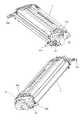
[プロセスカートリッジの構成]
次に図2及び図3を参照して、カートリッジ7の全体構成について説明する。本実施形態のカートリッジ7は、イエロー色の現像剤を有するカートリッジ7Y、マゼンタ色の現像剤を有するカートリッジ7M、シアン色の現像剤を有するカートリッジ7C、ブラック色の現像剤を有するカートリッジ7Kが同一構成である。そして、各カートリッジ7は、感光体ドラム1の周囲にプロセス手段としての帯電手段、現像手段、クリーニング手段を有している。[Process cartridge configuration]
Next, the entire configuration of the
感光体ドラム1は、シリンダーとして例えばアルミシリンダー63の外周面に感光層を設けたものである。感光体ドラム1は、前記シリンダー63の両端部を軸によって回転自在に支持されている。そして、一方の端部に駆動モータからの駆動力が伝達される。これによって、前記感光体ドラム1は回転駆動(反時計回り方向)する。 The
帯電手段は感光体ドラム1の表面を一様に帯電するものである。本実施形態では帯電手段としてローラ形状の導電性の帯電ローラ2を用いている。帯電ローラ2はバネ等の弾性手段により付勢され、感光体ドラム1の表面に当接される。帯電ローラ2は帯電バイアス電圧の印加により、感光体ドラム1の表面を一様に帯電する。 The charging means uniformly charges the surface of the
現像手段は感光体ドラム1に形成された前記静電潜像を現像剤を用いて現像するものである。現像を行う構成について説明する。現像剤を収納した現像剤収納容器(現像剤収納部)41内の現像剤を送り機構42によって現像剤供給ローラ43へ送り込む。前記供給ローラ43は、時計回り方向(図2)に回転する。そして、前記供給ローラ43は、現像ローラ40への現像剤の供給、及び、現像を行った後の現像ローラ40から現像剤をはぎ取る。前記現像ローラ40へ供給された現像剤は、現像ローラ40の外周に圧接された現像ブレード44によって現像ローラ40の外周に塗布される。かつ、前記現像剤に電荷を付与される。そして、前記現像ローラ40に装置本体100Aから現像バイアスを印加する。これによって、前記現像ローラ40は、現像剤を用いて、前記潜像を現像する。尚、前記現像ローラ40は、前記感光体ドラム1の長手方向に沿って配置されている。また、前記現像ローラ40は、図2の時計回り方向に回転する。 The developing means develops the electrostatic latent image formed on the
ここで、前記現像剤収納容器41、前記供給ローラ43、前記現像ローラ40、及び、前記現像ブレード44は、現像ユニット4に設けられている。 Here, the
クリーニング手段は、現像剤像を感光体ドラム1に転写した後の感光体ドラム1に残留した現像剤を除去するものである。クリーニング手段としてのクリーニングブレード60は、クリーナユニット50に設けられている。すなわち、クリーナユニット50には、感光体ドラム1の表面に残留する現像剤を除去するためのクリーニングブレード60、前記ブレード60によって感光体ドラム1表面から除去された現像剤を収納する除去現像剤収納室(除去現像剤収納部)55、及び、前記ブレード60によって除去した現像剤をクリーニング枠体51から漏れ出るのを防止する可撓性シート80が設けられている。前記シート80は、その先端が感光体ドラム1に軽く接触している。 The cleaning unit removes the developer remaining on the
尚、前記ユニット50には、前記クリーニング手段の他に、感光体ドラム1及び帯電ローラ2が設けられている。そして、図2及び図3に示すように、前記クリーナユニット50と現像ユニット4とを回動可能に結合させている。これによって、カートリッジ7が構成されている。 The
詳述すると、前記クリーナユニット50には、感光体ドラム1が軸受30,31を介してクリーニング枠体51に回動自在に取り付けられている。前述した通り、前記感光体ドラム1には、帯電ローラ2、クリーニングブレード60、シート80が当接している。また、現像剤収納室55が配設されている。 More specifically, the
現像ユニット4は、現像枠体45a,45bを超音波溶着により結合して構成した現像容器枠体46を有する。この容器枠体46に、前記現像ローラ40、現像剤収納容器41、現像剤供給ローラ43、及び、現像ブレード44が設けられている。 The developing
前記容器枠体46の両端に設けた結合穴47,48と前記クリーニング枠体51の両端に設けた支持穴52,53とを合わせる。そして、前記各穴に、前記枠体51の両端からピン(不図示)を差し込む。これによって、前記現像ユニット4が前記クリーナユニット50に対して回動可能に結合されている。 The coupling holes 47 and 48 provided at both ends of the
また、前記現像ローラ40がスペーサーコロ(不図示)を介して、前記感光体ドラム1を押圧するように、弾性部材であるバネ(不図示)の弾性力によって、現像ユニット4がクリーナユニット50の方向へ常に付勢されている。尚、前記バネ(不図示)は、ユニット50の長手方向両側に取り付けられている。 Further, the developing
[画像形成装置本体に対するプロセスカートリッジの着脱構成]
次に、図3及び図4を参照して、画像形成装置100の装置本体100Aに対してカートリッジ7を取り外し可能に装着するための装着手段の構成について説明する。[Configuration of attaching / detaching process cartridge to / from image forming apparatus main body]
Next, with reference to FIG. 3 and FIG. 4, the configuration of the mounting means for detachably mounting the
図4に示すように、画像形成装置本体100には、前扉101が開閉可能に設けられている。また、前扉101の内側には前記転写ベルト11が取り付けられている。従って、前扉101と前記転写ベルト11は一体に、前記装置本体100Aに対して開閉可能に設けられている。前記前扉101、及び、前記転写ベルト11が開いた状態で、カートリッジ7は装置本体100Aに対して着脱可能である。 As shown in FIG. 4, the image forming apparatus
なお、図3に示すように、カートリッジ7の長手方向両側には、カートリッジ7を装置本体100Aに着脱する際のガイドとなるガイド部30a,31aが設けられている。また、前記カートリッジ7の長手方向両端には、把手部30b,31bが設けられている。 As shown in FIG. 3, guide
一方、前記装置本体100Aには、前記ガイド部30a,31aを案内するガイドレール(不図示)が設けられている。 On the other hand, the apparatus
前記ガイド部30a,31aを前記ガイドレールに沿わせて、カートリッジ7を装置本体100A内へ挿入する。これによって、装置本体100Aに対してカートリッジ7を装着することができる。また前記ガイド部30a,31aを前記ガイドレールに沿わせてカートリッジ7を引き出す。これによって、装置本体100Aからカートリッジ7を取り外すことができる。このとき、操作者が前記把手部30b,31bを把持することで、カートリッジ7の装着及び取り外しを容易に行うことができる。 The
[画像形成装置本体に対する感光体ドラムの位置決め構成]
次に図5〜図8を用いて、画像形成装置本体100Aに対する感光体ドラム1の位置決め構成について説明する。[Positioning structure of photosensitive drum relative to image forming apparatus main body]
Next, a positioning configuration of the
画像形成装置本体100Aには、前記感光体ドラム1に駆動力を伝達するための駆動力伝達機構が設けられている。 The image forming apparatus
図5、図6及び図9に示すように、装置本体100Aに設けられた前記伝達機構は、モータ(不図示)と、前記モータからの駆動力を伝達するための装置本体ギアとしての駆動ギア71と、前記駆動ギア71の中央部に設けられた軸部71dと、前記軸部71dの先端に設けられた、断面(軸線方向と直交する)が複数個の角部を有する非円形のねじれた穴71aと、を有する。この駆動ギア71の中央部、即ち、前記軸部71dの中央部には駆動軸70が設けられている。この駆動軸70は、前記駆動ギア71、及び、前記軸部71dを貫通している。そして、前記駆動軸70の先端には、球状形状の球状部70aが設けられている。尚、前記球状部70aは、前記穴71aの中央部に配置されている。そして、前記球状部70aは、前記穴71aの縁(先端面)から軸線方向外方へ突出して設けられている。 As shown in FIGS. 5, 6, and 9, the transmission mechanism provided in the apparatus
次に、カートリッジ7に設けられているの駆動力受け機構について説明する。 Next, the driving force receiving mechanism provided in the
図6に示すように、前記感光体ドラム1は、周面に感光層を有するシリンダ63の長手方向一端にフランジ部材61、他端にフランジ部材62が結合されている。このフランジ部材61の先端に設けられた軸部61aを軸受部材31(図3参照)が回転可能に支持している。また、軸受部材30がフランジ部材62の先端に設けられた軸部62aを回転可能に支持している。また、図5に示すように、前記軸部61aの先端には、画像形成装置本体100から駆動力を受けるためのドラム駆動力受け部としての、断面が複数の角部を有する非円形のねじれた突起61bが設けられている。前記突起61bは、カートリッジ7が装置本体100に装着された際に、前記穴71aと嵌合する。そして、前記突起61bが前記穴71aと嵌合して前記感光体ドラム1を回転するための駆動力を前記装置本体100Aから受ける。より詳細には、前記穴71aと前記突起61bとが嵌合した状態で、前記駆動ギア71が回転する。これによって、前記突起が61bが前記穴71aの方向へ引き込み力を受けた状態で、前記駆動ギア71の回転力を前記穴71aと前記突起61bとを介して前記感光体ドラム1に伝達する。 As shown in FIG. 6, the
そして、図7に示すように、前記突起61bは、その中央部に凹部としての溝65を有している。この溝65は、前記穴71aから突出して設けられた球状部70aの球面形状の球面部70a2と当接する底部(底面部分)65aと、前記球面部70a2と当接する側面部65bとを有する。よって、前記突起61bが前記穴71aと嵌合して前記感光体ドラム1を回転するための駆動力を前記装置本体100Aから受ける際に、前記球面部70a2の先端と前記底部65aとを当接し、及び、前記球面部70a2と前記側面部65bとを当接する。尚、本実施形態によれば、前記側面部65bは、前記底部65aに対して、略直角に設けられている。より詳細には、前記穴71aと前記突起61bとが嵌合した状態で、前記球面部70a2の先端(頂点)と前記底部65aとが当接する(図7において、当接点65a1)。前記球面部70a2の先端(頂点)は、感光体ドラム1の軸線と実質的に同軸線上で前記底部65aと接触する。また、前記球面部70a2の側面と前記側面部65bとが当接する(図7において、当接点61a2)。この際、前記球面部70a2は、感光体ドラム1の軸線と実質的に同軸線上で接触する。そして前記駆動ギア71が回転する。これによって、前記突起が61bが前記穴71aの方向へ引き込み力(スラスト力)を受けた状態で、前記駆動ギア71の回転力を前記穴71aと前記突起61bとを介して前記感光体ドラム1に伝達する。この際に、前記溝65と前記球状部70aとが嵌合する。そして、前記引き込み力(スラスト力)によって、前記底部65aが前記球面部70a2に押圧する。これによって、前記底部65aと前記球面部70a2がより確実に当接する。また、これによって、前記球面部70a2と側面部65bとがより確実に当接する。尚、前記溝65は、軸線方向と交差する断面が円形である。即ち、前記溝65は、円柱形状である。そして、前記溝65の内径と前記球状部70aの外径は略同じ大きさである。従って両者は嵌合する。尚、略同じ大きさとした理由は、前記球状部70aが前記溝65内へ必ず進入するように、前記球状部70aの外径を前記溝65の内径よりも僅かに小さくしているからである。これは、製造公差を考慮したものである。
また、前記溝65は前記軸線と同軸線上に設けられている。そして、前記球面部70a2は、前記軸線と実質的に同軸線上で前記側面部65bと接触する。また、前記球面部70a2は、前記底部65aの平面部分でもって、前記底部65aと接触する。And as shown in FIG. 7, the said
The
前記球面部70a2と前記底部65aとが、感光体ドラム1の長手方向、即ち、前記軸線方向(スラスト方向)において当接する。これにより、前記装置本体100Aに対する前記感光体ドラム1の前記長手方向(スラスト方向)の位置が決められる。また、前記球状部70aの側面と前記側面部65bとが、感光体ドラム1の長手方向と直交する方向において当接する。これにより、前記装置本体100Aに対する前記感光体ドラム1の長手方向と直交する方向の位置決めが行われる。即ち、前記感光体ドラム1の前記装置本体100Aに対するラジアル方向(ドラム半径方向)の位置が決まる。また、前記感光体ドラム1の長手方向においては、前記溝65は、前記球状部70aと重なった位置に設けられている。よって、前記長手方向の寸法を短くすることができる。 The spherical surface portion 70a2 and the
また、図7に示すように、本実施形態において、前記穴71aはねじれており、前記断面が略三角形である。より好ましくは、略正三角形である。また、前記突起61bはねじれており、その形状は、略三角柱形状である。より好ましくは、略正三角柱である。尚、前記穴71aの断面が略正三角形であり、また、前記突起61bの形状が略正三角柱である場合には、前記穴71aと前記突起61bとが実質的に調芯する精度が向上する。即ち、前記駆動ギア71と前記感光体ドラム1とが実質的に調芯する精度が向上する。 Moreover, as shown in FIG. 7, in this embodiment, the said
なお、本実施形態では、前記穴71aの形状として、断面が略三角形のねじれた穴を例示した。また、前記突起61bの形状として、ねじれた三角柱形状の突起を例示した。しかしながら、本発明はこれに限定されるものではない。前記穴は、断面が複数の角部を有する非円形のねじれた穴であればその他の形状であっても良い。同様に、前記突起は、断面が複数の角部を有する非円形のねじれた突起であればその他の形状であっても良い。前記断面が複数の角部を有する非円形のねじれた穴と嵌合する、断面が複数の角部を有する非円形のねじれた突起であればその他の構成であっても良い。すなわち、前記穴と前記突起とが嵌合した状態で前記駆動ギアが回転することによって、前記突起と前記穴とが実質的に調芯する。そして、前記突起が前記穴の方向へ引き込み力を受けた状態で、感光体ドラムが装置本体から駆動力を受ける構成であれば、前記穴及び突起の形状は前記形状に限定されるものではない。 In the present embodiment, the
図6、及び、図8に示す通り、前記駆動ギア71の軸部71dの外径Xは、装置本体100Aに設けられた支持枠体(支持部材)74の有する穴部74aの内径Yに対して小さく(X<Y)設定している(図6、図8)。従って、穴部74aの内径Y内で、前記軸部71dは、ラジアル方向(半径方向)に可動である。そして、前記感光体ドラム1と駆動ギア71とを結合した状態、即ち、前記穴71aと前記突起61bとが嵌合した状態では、駆動ギア71と前記支持枠体74とは当接しない。即ち、前記軸部71dと前記穴74aの内面とは接触しない。よって、駆動ギア71は円滑に回転する。尚、前記穴71aと前記突起61bとが嵌合していない場合には、前記軸部71dは前記穴74aの内面に接触している。即ち、前記軸部71dは前記支持枠体74によって支持される。また、感光体ドラム1から離れている方の駆動ギア71の位置決め部71cは、軸受73を介して装置本体100Aに設けられた支持枠体72に支持されている。即ち、装置本体100Aに対して摺動可能に、また、必要最小な隙間で支持枠体72に支持される。従って、前記駆動ギア71は、前記回転駆動力の伝達が行われる際に、前記感光体ドラム1に対してラジアル方向(半径方向)が位置決めされる。即ち、前記駆動ギア71は前記感光体ドラム1にならって、前記ラジアル方向の位置が決まる。尚、前述した通り、感光体ドラム1の両端はカートリッジ枠体に設けられた軸受30,31によって支持されている。従って、感光体ドラム1のラジアル方向(半径方向)は、位置決めされている。これによって、装置本体100Aに設けられた駆動軸70と感光体ドラム1の軸線は同軸線上に位置決めされる。尚、駆動軸70は、前記駆動ギア71に一体に取り付けられている。そして、前記駆動軸70、及び、前記駆動ギア71は、前記軸線方向に対しては固定に、前記軸受73に取り付けられている。これに対して、前記感光体ドラム1は、前記軸線方向に対して可動に、前記軸受30,31支持されている。 As shown in FIGS. 6 and 8, the outer diameter X of the
このようにして感光体ドラム1と駆動ギア71とを同軸線上に位置決めしても、前記駆動軸70の軸線が感光体ドラム1の軸線に対して微小に傾くことがある。これは、それぞれを支持する組立部品の部品公差が有るからである。尚、この傾き量を偏角θと呼ぶ。図7に示すように、本実施形態では、前記球状部70aと前記溝65の底部65aとを当接して位置決めする。従って、前記突起61bの先端面61b1と前記穴71aの底面70a1との間に隙間Uが確保される。本実施形態によれば、これにより例え偏角θが発生した場合であっても、前記突起61bの先端面61b1と前記穴71aの底面70a1との間に常に隙間Uが確保される(図7参照)。そのため、前記球面部70a2の頂点が必ず前記底部65aと接触する。従って、駆動ギア71(駆動軸70)の軸線が感光体ドラム1の軸線に対して傾くことが発生したとしても、感光体ドラム1の回転変動を抑制することができる。即ち、本実施形態の場合には、偏角θが発生したとしても、感光体ドラム1に回転ムラが発生しない。これは、前記感光体ドラム1の軸線部分でもって、前記球面部70a2の先端(頂点)が前記底面65aに常に接触するからである。即ち、例え偏角θが発生したとしても、前記感光体ドラム1の軸線部分において、前記球面部70a2の先端(頂点)が前記底面65aに接触するからである。従って、各カートリッジ7が有する感光体ドラム1の回転変動を抑制することができるので、フルカラー画像を形成する際に、色ずれが発生するのを抑制することができる。 Even if the
尚、71bはギア部であり、具体的にははす歯ギアである。 In addition, 71b is a gear part and is a helical gear specifically.
上述したように、本実施形態によれば、突起61bと穴71aとが嵌合して駆動力を伝達する際に発生する、穴71aが突起61bを引き込む力によって、感光体ドラム1の軸線方向を装置本体100Aに対して位置決めすることができる。また、前記球状部70aと、前記溝65の底部65aとを当接させることで、感光体ドラム1の軸線に対して駆動ギア71の軸線が傾むいたとしても、感光体ドラム1の回転変動(回転ムラ)を抑えることができる。その結果、各カートリッジ7が有する感光体ドラム1の回転差が発生することを抑制することができる。従って、精度良く感光体ドラム1の回転を制御できる。よって、感光体ドラム1の回転ムラによる色ずれを最小限に抑えることができ、より高画質のカラー画像を得ることができる。 As described above, according to the present embodiment, the axial direction of the
ここで、図10を用いて、本発明を適用した前述実施例と、比較実施例の場合の効果の比較結果を示す。図10は、本発明を適用した実施例の感光体ドラムの回転ムラと、比較例の感光体ドラムの回転ムラとを比較するための測定データを示したものである。比較実施例は、感光体ドラムの前記長手方向の位置決めを、本体に設けられた穴の底面としての平面と、カートリッジに設けられた突起の先端面としての平面とを当接させて行う構成である。比較実施例では、このような構成において、前記偏角を0.3度として実験を行った。一方、本発明を適用した前述実施例において、同様に前記偏角を0.3度として実験を行った。図10(a)は、本発明を適用した前述実施例の場合の感光体ドラムの回転変動(回転ムラ)を示す。又、図10(b)は、前述比較実施例の場合の感光体ドラムの回転変動(回転ムラ)を示す。縦軸に回転変動量、横軸に時間を示す。この図から理解されるように、図10(a)に示す本発明を適用した前述実施例の場合の方が、図10(b)に示す比較実施例の場合と比べて、時間当り(ドラム1周期当り)の回転変動量が少ない。 Here, FIG. 10 is used to show the comparison results of the effects of the above-described embodiment to which the present invention is applied and the comparative embodiment. FIG. 10 shows measurement data for comparing the rotation unevenness of the photosensitive drum of the example to which the present invention is applied and the rotation unevenness of the photosensitive drum of the comparative example. In the comparative example, the positioning of the photosensitive drum in the longitudinal direction is performed by bringing a flat surface as the bottom surface of the hole provided in the main body into contact with a flat surface as the tip surface of the protrusion provided in the cartridge. is there. In the comparative example, in such a configuration, the experiment was performed with the declination being 0.3 degrees. On the other hand, in the above-mentioned embodiment to which the present invention was applied, the experiment was similarly performed with the declination being 0.3 degrees. FIG. 10A shows the rotational fluctuation (rotational unevenness) of the photosensitive drum in the case of the above-described embodiment to which the present invention is applied. FIG. 10B shows the rotational fluctuation (unevenness of rotation) of the photosensitive drum in the comparative example. The vertical axis represents the rotational fluctuation amount, and the horizontal axis represents time. As can be understood from this figure, in the case of the above-described embodiment to which the present invention shown in FIG. 10A is applied, the time per unit (drum) is compared with the case of the comparative embodiment shown in FIG. The amount of fluctuation in rotation per cycle is small.
即ち、本発明を適用した実施例の場合には、偏角が発生したとしても、感光体ドラムに回転ムラが発生しない。これは、前記感光体ドラムの軸線部分でもって、前記球面部の先端(頂点)が前記底面に常に接触するからである。即ち、例え偏角が発生したとしても、前記感光体ドラムの軸線部分において、前記球面部の先端(頂点)が前記底面に接触するからである。 That is, in the embodiment to which the present invention is applied, even if a declination occurs, no rotation unevenness occurs on the photosensitive drum. This is because the tip (vertex) of the spherical portion always contacts the bottom surface at the axial portion of the photosensitive drum. That is, even if a declination occurs, the tip (vertex) of the spherical portion contacts the bottom surface in the axial portion of the photosensitive drum.
尚、この測定時には、感光体ドラムの回転トルクを3kgf・cmとした。これは、実際のカートリッジの場合と同様のトルクとするためである。 In this measurement, the rotational torque of the photosensitive drum was 3 kgf · cm. This is because the torque is the same as that of an actual cartridge.
次に、図8を用いて、球状部70aを介して、感光体ドラム1を装置本体100Aに接地する構成について説明する。即ち、装置本体100Aとの間で、感光体ドラム1のアースを行う構成について説明する。その他の構成については、前述した構成と同じであり、説明を援用する。 Next, a configuration in which the
前記駆動軸70及び球状部70aを導電性とする。そして、図8に示すように、前記駆動軸70の後端に接点部材77を接触している。また、前記接点部材77の一端を前記支持枠体72に取り付けている。ここで、前記接点部材77及び前記支持枠体72は、板金製であって、導電性である。従って、球状部70、駆動軸70a、接点部材77、及び、支持枠体72は、電気的に接続している。また、本実施形態によれば、前記溝65の底部65a(図8参照)には、前記感光体ドラム1の導電性シリンダー63と電気的に接続した前記底部としての導電性アース板金(アース電気接点)76が設けられている。即ち、前記溝65の内側には、前記底部としての、前記シリンダー63と電気的に接続したアース電気接点としてのアース板金76であって、前記突起61bが前記穴71aと嵌合して前記感光体ドラム1を回転するための駆動力を前記装置本体100Aから受ける際に、前記引き込み力によって前記球状部70aに押圧するアース板金76が設けられている。そして、このアース板金76は、カートリッジ7が装置本体100Aに装着された際に、前記球面部70a2の先端と接触する。尚、前記先端が接触する、前記底部としての前記板金76の部分は平面である。従って、突起61bと穴71aとが嵌合して回転力が感光体ドラム1に伝達される際に、感光対ドラム1は、アース板金76、球状部70、駆動軸70a、接点部材77、及び、支持枠体72を介して、装置本体100Aと電気的に接続される。この際に、前記引き込み力によって、前記アース板金76が前記球状部70に押圧される。従って、両者の電気的接続が確実に行われる。又、前記アース板金が有する弾性力によって、両者が弾性的に接続する。これによっても、両者の電気的接続が確実に行われる。したがって、感光体ドラム1のアースが確実に行われる。 The
このように構成にすることで、感光体ドラム1と感光体ドラム1の駆動軸70との電気的接続部、即ち、アース板金76と球状部70とが接触している部分は摺動ではなく、固定にすることができる。これは、感光体ドラム1と駆動軸70aとが一体に回転する為である。そのため、装置本体に100Aに対して着脱するカートリッジ7と装置本体100Aとの電気的接続の安定性を実現した。 With this configuration, the electrical connection portion between the
また、回転駆動力伝達時に生じる、穴71aが突起61bを引き込む力を、前記球状部70aと前記アース板金76との接点圧としている。そのため、接点のへたりを懸念する必要がない。また、回転駆動力の伝達が行われているときのみ前記接点圧がかかる。そして、前記駆動力の伝達を行なっていない状態(駆動力の伝達オフ時)においては前記引き込み力は発生せず(引き込み力オフ時)、また、前記駆動力の伝達を行う状態(駆動力の伝達オン時)においては前記引き込み力が発生する(引き込み力オン時)。この引き込み力のオン、オフの切り替えにより発生する、感光体ドラム1の前記軸線方向の微少変位により、球状部70aとアース板金76との接点部でワイピング効果を得ることができる。 Further, the force that the
また、図5に示すように、前記溝65は軸線方向と交差する断面が円形である。前記溝65の断面を円形にすることによって、凹部の領域を最小限にすることができる。よって、前記突起61bの強度を維持しつつ、前記突起61bの大きさを小さくすることができる。従って、前記突起61bが嵌合する前記穴71aの大きさも小さくすることができる。すなわち、カートリッジ7と装置本体100Aの小型化を実現することができる。 Further, as shown in FIG. 5, the
1(1Y,1M,1C,1K) …感光体ドラム(電子写真感光体ドラム)
2(2Y,2M,2C,2K) …帯電ローラ(帯電手段)
4(4Y,4M,4C,4K) …現像ユニット(現像手段)
7(7Y,7M,7C,7K) …プロセスカートリッジ
30,31 …軸受
40 …現像ローラ
45a,45b …現像枠体
50(50Y,50M,50C,50K) …クリーナユニット(クリーニング手段)
51 …クリーニング枠体
60 …クリーニングブレード
61,62 …フランジ部材
65 …溝(凹部)
65a …底部
65b …側面部
61b …突起
63 …シリンダー
70 …駆動軸
70a …球状部
70a2 …球面部
71 …駆動ギア(装置本体ギア)
71a …穴
76 …アース板金(アース電気接点)
100 …電子写真画像形成装置
100A・・・電子写真画像形成装置本体1 (1Y, 1M, 1C, 1K) ... photosensitive drum (electrophotographic photosensitive drum)
2 (2Y, 2M, 2C, 2K) ... charging roller (charging means)
4 (4Y, 4M, 4C, 4K) ... development unit (development means)
7 (7Y, 7M, 7C, 7K) ...
51 ...
65a ... Bottom 65b ...
71a ...
DESCRIPTION OF
Claims (11)
Translated fromJapanese(a)周面に感光層を有するシリンダーと、
(b)前記シリンダーの長手方向の一端に設けられた突起であって、前記プロセスカートリッジが前記装置本体に装着された際に前記装置本体に設けられた前記穴と嵌合して、前記装置本体から駆動力の伝達を受けるための、断面が複数個の角部を有する非円形のねじれた突起と、
前記突起の中央部に設けられた凹部であって、前記穴と前記突起とが嵌合した状態で前記装置本体ギアが回転することによって、前記突起が前記穴の方向へ引き込み力を受けた状態で、前記穴の中央部に設けられた球面部の先端と当接する底部と、前記球面部と当接する側面部と、を有する凹部と、
を有し、
前記プロセスカートリッジが前記装置本体に装着された際であって、前記突起が前記穴と嵌合して前記電子写真感光体ドラムを回転するための駆動力を前記装置本体から受ける際に、前記引き込み力を受けた状態で、かつ、前記突起の先端面及び側面部と前記穴との間に隙間を有した状態で、前記球面部の先端と前記底部とを当接し、及び、前記球面部と前記側面部とを当接して回転するように構成したことを特徴とする電子写真感光体ドラム。A motor, a device main body gear for transmitting a driving force of the motor, and a non-circular cross section provided in a central portion of the device main body gear and having a plurality of corners rotating integrally with the device main body gear; An electrophotographic photosensitive drum for use in a process cartridge that has a twisted hole and is detachable from an apparatus main body of an electrophotographic image forming apparatus that forms an image on a recording medium,
(A) a cylinder having a photosensitive layer on its peripheral surface;
(B) A protrusion provided at one end in the longitudinal direction of the cylinder, and when the process cartridge is attached to the apparatus main body, the protrusion is fitted into the hole provided in the apparatus main body, A non-circular twisted protrusion having a plurality of cornersin cross section for receiving a driving force from
State a recess provided in a central portion of the projection, by the apparatus main body gear is rotated in a state that said said bore projection fitted, it said protrusion is subjected to a force pulling in the direction of the holein a recess having a distal end of the spherical surface portion provided at the center of the hole and abutting the bottom portion, the spherical portion that abuts the side surface portion,
Have
When the process cartridge is mounted on the apparatus main body, thepull-in is performed when the driving force for rotating the electrophotographic photosensitive drum is received from the apparatus main body by fitting the protrusion into the hole.The tip of the spherical surface and the bottomare brought into contact with each other in a state in which a force is received and there is a gap between the tip and side surfaces of the protrusion and the hole , and the spherical portion an electrophotographic photosensitive drum, characterizedby being configured to rotate in contact with said side surface portion.
(a)電子写真感光体ドラムと、
(b)前記電子写真感光体ドラムに作用するプロセス手段と、
(c)前記電子写真感光体ドラムの長手方向の一端に設けられた突起であって、前記プロセスカートリッジが前記装置本体に装着された際に前記装置本体に設けられた前記穴と嵌合して、前記装置本体から駆動力の伝達を受けるための、断面が複数個の角部を有する非円形のねじれた突起と、
前記突起の中央部に設けられた凹部であって、前記穴と前記突起とが嵌合した状態で前記装置本体ギアが回転することによって、前記突起が前記穴の方向へ引き込み力を受けた状態で、前記穴の中央部に設けられた球面部の先端と当接する底部と、前記球面部と当接する、前記底部と略直交する側面部と、を有する凹部と、
を有し、
前記プロセスカートリッジが前記装置本体に装着された際であって、前記突起が前記穴と嵌合して前記電子写真感光体ドラムを回転するための駆動力を前記装置本体から受ける際に、前記引き込み力を受けた状態で、かつ、前記突起の先端面及び側面部と前記穴との間に隙間を有した状態で、前記球面部の先端と前記底部とを当接し、及び、前記球面部と前記側面部とを当接して、前記感光体ドラムを回転するように構成したことを特徴とするプロセスカートリッジ。A motor, a device main body gear for transmitting a driving force of the motor, and a non-circular cross section provided in a central portion of the device main body gear and having a plurality of corners rotating integrally with the device main body gear; A process cartridge that has a twisted hole and is detachable from an apparatus main body of an electrophotographic image forming apparatus that forms an image on a recording medium,
(A) an electrophotographic photosensitive drum;
(B) process means acting on the electrophotographic photosensitive drum;
(C) A protrusion provided at one end in the longitudinal direction of the electrophotographic photosensitive drum, and is fitted into the hole provided in the apparatus main body when the process cartridge is attached to the apparatus main body. A non-circular twisted projection having a plurality of cornersin cross section for receiving a driving force from the device body;
State a recess provided in a central portion of the projection, by the apparatus main body gear is rotated in a state that said said bore projection fitted, it said protrusion is subjected to a force pulling in the direction of the holein a recess having a distal end of the spherical surface portion provided at the center of the hole and abutting the bottom, the a contact spherical portion, said bottom portion and side portions substantially perpendicular, and
Have
When the process cartridge is mounted on the apparatus main body, thepull-in is performed when the driving force for rotating the electrophotographic photosensitive drum is received from the apparatus main body by fitting the protrusion into the hole.The tip of the spherical surface and the bottomare brought into contact with each other in a state in which a force is received and there is a gap between the tip and side surfaces of the protrusion and the hole , and the spherical portionby contact with said side surfaceportion, the process cartridge characterizedby being configured to rotate the photosensitive drum.
(a)モータと、
(b)前記モータからの駆動力を伝達するための装置本体ギアと、
(c)前記装置本体ギアの中央部に設けられた、前記装置本体ギアと一体に回転する断面が複数個の角部を有する非円形のねじれた穴と、
(d)前記穴の中央部に設けられた球面部と、
(e)電子写真感光体ドラムと、
前記電子写真感光体ドラムに作用するプロセス手段と、
前記電子写真感光体ドラムの長手方向の一端に設けられた突起であって、前記プロセスカートリッジが前記装置本体に装着された際に前記穴と嵌合して、前記装置本体から駆動力の伝達を受けるための、断面が複数個の角部を有する非円形のねじれた突起と、
前記突起の中央部に設けられた凹部であって、前記穴と前記突起とが嵌合した状態で前記装置本体ギアが回転することによって、前記穴が前記突起の方向へ引き込み力を受けた状態で、前記球面部の先端と当接する底部と、前記球面部と当接する、前記底部と略直交する側面部と、を有する凹部と、
を有する前記プロセスカートリッジであって、装着手段に取り外し可能に装着されている前記プロセスカートリッジと、
(f)前記記録媒体を搬送する搬送手段と、
を有し、
前記プロセスカートリッジが前記装置本体に装着された際であって、前記突起が前記穴と嵌合して前記電子写真感光体ドラムを回転するための駆動力を前記装置本体から受ける際に、前記引き込み力を受けた状態で、かつ、前記突起の先端面及び側面部と前記穴との間に隙間を有した状態で、前記球面部の先端と前記底部とを当接し、及び、前記球面部と前記側面部とを当接して、前記感光体ドラムを回転するように構成したことを特徴とする電子写真画像形成装置。In an electrophotographic image forming apparatus for detaching a process cartridge and forming an image on a recording medium,
(A) a motor;
(B) an apparatus main body gear for transmitting a driving force from the motor;
(C) a non-circular twisted hole provided in a central portion of the apparatus main body gear and having a plurality of corners in a cross section that rotates integrally with the apparatus main body gear;
And (d) the sphericalsurface portion provided in a central portion of said hole,
(E) an electrophotographic photosensitive drum;
Process means acting on the electrophotographic photosensitive drum;
A projection provided at one end in the longitudinal direction of the electrophotographic photosensitive drum, which fits into the hole when the process cartridge is mounted in the apparatus main body, and transmits a driving force from the apparatus main body. for receivinga protrusion section is twisted a non-circular having a plurality of corners,
A recess provided in a central portion of the protrusion,the state the main assembly gear in a state that said said bore projection fitted is by rotating, said hole receives a force pulling in the direction of the projectionin a recess having a tip that abuts the bottom of the spherical portion, the contact with the spherical surface portion, said bottom portion and side portions substantially perpendicular, and
The process cartridge, wherein the process cartridge is removably mounted on a mounting means;
(F) conveying means for conveying the recording medium;
Have
When the process cartridge is mounted on the apparatus main body, thepull-in is performed when the driving force for rotating the electrophotographic photosensitive drum is received from the apparatus main body by fitting the protrusion into the hole.The tip of the spherical surface and the bottomare brought into contact with each other in a state in which a force is received and there is a gap between the tip and side surfaces of the protrusion and the hole , and the spherical portionby contact with said side surfaceportion, the photosensitive drum electrophotographic image forming apparatus characterizedby being configured to rotate.
前記底部には、前記電子写真感光体ドラムが有するシリンダーと電気的に接続したアース電気接点であって、前記突起が前記穴と嵌合して前記電子写真感光体ドラムを回転するための駆動力を前記装置本体から受ける際に前記引き込み力によって前記球面部に押圧するアース電気接点が前記プロセスカートリッジに設けられていることを特徴とする請求項9に記載の電子写真画像形成装置。The sphericalsurface portion is connected to the apparatus body and electrically conductive,
The bottom portion is a ground electric contact electrically connected to a cylinder of the electrophotographic photosensitive drum, and the driving force for rotating the electrophotographic photosensitive drum with the protrusion fitted into the hole an apparatus according to claim 9, characterized in that grounding electrical contact for pressing said sphericalsurface portion is provided on said process cartridge by said drawing force when receiving from said apparatus main body.
Priority Applications (6)
| Application Number | Priority Date | Filing Date | Title |
|---|---|---|---|
| JP2004283318AJP3885074B2 (en) | 2004-05-11 | 2004-09-29 | Electrophotographic photosensitive drum, process cartridge, and electrophotographic image forming apparatus |
| US10/960,054US7209682B2 (en) | 2004-05-11 | 2004-10-08 | Electrophotographic photosensitive drum, process cartridge, and electrophotographic image forming apparatus |
| CNB2004100903866ACN100458584C (en) | 2004-05-11 | 2004-11-12 | Electrophotographic photosensitive drum, process cartridge, and electrophotographic image forming apparatus |
| EP05009735.1AEP1628165B1 (en) | 2004-05-11 | 2005-05-03 | Electrophotographic photosensitive drum, process cartridge, and electrophotographic image forming apparatus |
| KR1020050038652AKR100810179B1 (en) | 2004-05-11 | 2005-05-10 | Electrophotographic photosensitive drum, process cartridge, and electrophotographic image forming apparatus |
| US11/616,486US7440715B2 (en) | 2004-05-11 | 2006-12-27 | Electrophotographic photosensitive drum, process cartridge, and electrophotographic image forming apparatus |
Applications Claiming Priority (2)
| Application Number | Priority Date | Filing Date | Title |
|---|---|---|---|
| JP2004140695 | 2004-05-11 | ||
| JP2004283318AJP3885074B2 (en) | 2004-05-11 | 2004-09-29 | Electrophotographic photosensitive drum, process cartridge, and electrophotographic image forming apparatus |
Publications (2)
| Publication Number | Publication Date |
|---|---|
| JP2005352438A JP2005352438A (en) | 2005-12-22 |
| JP3885074B2true JP3885074B2 (en) | 2007-02-21 |
Family
ID=35309534
Family Applications (1)
| Application Number | Title | Priority Date | Filing Date |
|---|---|---|---|
| JP2004283318AExpired - Fee RelatedJP3885074B2 (en) | 2004-05-11 | 2004-09-29 | Electrophotographic photosensitive drum, process cartridge, and electrophotographic image forming apparatus |
Country Status (5)
| Country | Link |
|---|---|
| US (2) | US7209682B2 (en) |
| EP (1) | EP1628165B1 (en) |
| JP (1) | JP3885074B2 (en) |
| KR (1) | KR100810179B1 (en) |
| CN (1) | CN100458584C (en) |
Families Citing this family (46)
| Publication number | Priority date | Publication date | Assignee | Title |
|---|---|---|---|---|
| JP4695913B2 (en)* | 2005-04-12 | 2011-06-08 | キヤノン株式会社 | Electrophotographic image forming apparatus |
| JP4735073B2 (en) | 2005-06-24 | 2011-07-27 | 富士ゼロックス株式会社 | Image forming apparatus |
| JP4280770B2 (en) | 2006-01-11 | 2009-06-17 | キヤノン株式会社 | Process cartridge and electrophotographic image forming apparatus |
| JP4758247B2 (en)* | 2006-02-20 | 2011-08-24 | 株式会社東芝 | Drive transmission mechanism and image forming apparatus having the same |
| JP4498407B2 (en) | 2006-12-22 | 2010-07-07 | キヤノン株式会社 | Process cartridge, electrophotographic image forming apparatus, and electrophotographic photosensitive drum unit |
| JP4948382B2 (en) | 2006-12-22 | 2012-06-06 | キヤノン株式会社 | Coupling member for mounting photosensitive drum |
| JP5311854B2 (en) | 2007-03-23 | 2013-10-09 | キヤノン株式会社 | Electrophotographic image forming apparatus, developing device, and coupling member |
| JP5657064B2 (en)* | 2007-03-23 | 2015-01-21 | キヤノン株式会社 | Electrophotographic image forming apparatus and developing cartridge |
| US8229320B2 (en) | 2007-05-15 | 2012-07-24 | Canon Kabushiki Kaisha | Electrophotographic image forming apparatus, cartridge, and cartridge holding member with lock and lock releasing members for releasably locking cartridge to the cartridge holding member |
| JP4458377B2 (en) | 2007-06-29 | 2010-04-28 | キヤノン株式会社 | Process cartridge and electrophotographic image forming apparatus |
| JP4458378B2 (en) | 2007-06-29 | 2010-04-28 | キヤノン株式会社 | Process cartridge and electrophotographic image forming apparatus |
| JP5053743B2 (en)* | 2007-07-23 | 2012-10-17 | 株式会社リコー | Image forming apparatus |
| JP4948489B2 (en)* | 2007-08-10 | 2012-06-06 | キヤノン株式会社 | Image forming apparatus |
| NL1036459A1 (en) | 2008-02-13 | 2009-08-14 | Asml Netherlands Bv | Method and apparatus for angular-resolved spectroscopic lithography characterization. |
| JP5264207B2 (en)* | 2008-02-18 | 2013-08-14 | キヤノン株式会社 | Photosensitive drum and image forming apparatus |
| JP5127584B2 (en) | 2008-06-20 | 2013-01-23 | キヤノン株式会社 | Drum unit and electrophotographic image forming apparatus |
| JP5283986B2 (en)* | 2008-06-20 | 2013-09-04 | キヤノン株式会社 | Drum unit and electrophotographic image forming apparatus |
| JP4558083B2 (en) | 2008-06-20 | 2010-10-06 | キヤノン株式会社 | Cartridge, method for assembling the cartridge, and method for disassembling the cartridge |
| JP5419584B2 (en)* | 2008-09-01 | 2014-02-19 | キヤノン株式会社 | Cartridge and electrophotographic image forming apparatus |
| JP5335329B2 (en)* | 2008-09-01 | 2013-11-06 | キヤノン株式会社 | Image forming apparatus |
| JP5424749B2 (en)* | 2008-09-01 | 2014-02-26 | キヤノン株式会社 | cartridge |
| EP2333620A1 (en) | 2008-09-01 | 2011-06-15 | Canon Kabushiki Kaisha | Developing cartridge, process cartridge, and electrophotographic image forming apparatus |
| US8029284B2 (en)* | 2008-09-29 | 2011-10-04 | Maxillent Ltd. | Implants, tools, and methods for sinus lift and lateral ridge augmentation |
| JP5546187B2 (en) | 2008-10-22 | 2014-07-09 | キヤノン株式会社 | Image forming apparatus |
| JP5554963B2 (en)* | 2009-10-30 | 2014-07-23 | キヤノン株式会社 | Developing cartridge and process cartridge |
| JP5430349B2 (en)* | 2009-10-30 | 2014-02-26 | キヤノン株式会社 | Developer cartridge |
| JP5027897B2 (en)* | 2010-03-17 | 2012-09-19 | 京セラドキュメントソリューションズ株式会社 | Photosensitive drum support structure and image forming apparatus having the same |
| JP2012008504A (en)* | 2010-06-28 | 2012-01-12 | Fuji Xerox Co Ltd | Image forming device |
| JP5720144B2 (en)* | 2010-08-24 | 2015-05-20 | 富士ゼロックス株式会社 | Detachable body and image forming apparatus |
| CN102314118B (en)* | 2011-09-07 | 2015-01-21 | 珠海天威飞马打印耗材有限公司 | Driving assembly of photosensitive drum |
| TWI489226B (en) | 2011-12-06 | 2015-06-21 | 佳能股份有限公司 | Cartridge detachably mountable to main assembly of electrophotographic image forming apparatus, assembling method for drive transmitting device for photosensitive drum, and electrophotographic image forming apparatus |
| JP3183618U (en) | 2012-03-22 | 2013-05-30 | 三菱化学株式会社 | Rotating member for image forming apparatus, image forming cartridge, and image forming apparatus |
| CN110426937B (en)* | 2012-06-15 | 2022-08-19 | 佳能株式会社 | Processing box |
| US9058007B2 (en) | 2012-09-07 | 2015-06-16 | Mitsubishi Chemical Corporation | Torque transmitting member disposed at an end of a photosensitive drum, photosensitive drum unit, and process cartridge |
| US9182733B2 (en) | 2013-02-07 | 2015-11-10 | Canon Kabushiki Kaisha | Developer supply cartridge, process cartridge and image forming apparatus |
| CN104049484B (en)* | 2013-03-15 | 2017-08-11 | 纳思达股份有限公司 | Driving component for photosensitive element, handle box and handle box install detection method |
| JP6512864B2 (en) | 2015-02-27 | 2019-05-15 | キヤノン株式会社 | Cartridge, process cartridge, image forming apparatus |
| CN107430376B (en) | 2015-02-27 | 2021-05-14 | 佳能株式会社 | box |
| CN118050966A (en) | 2015-02-27 | 2024-05-17 | 佳能株式会社 | Drum units, cartridges and couplings |
| JP6337844B2 (en)* | 2015-06-30 | 2018-06-06 | 京セラドキュメントソリューションズ株式会社 | Image forming apparatus, photosensitive drum unit, bush member |
| GB2567779B (en) | 2016-08-26 | 2021-08-18 | Canon Kk | Cartridge and image forming apparatus |
| WO2018190386A1 (en) | 2017-04-12 | 2018-10-18 | Canon Kabushiki Kaisha | Image forming apparatus and cartridge |
| JP6957205B2 (en) | 2017-05-31 | 2021-11-02 | キヤノン株式会社 | Cartridge and image forming equipment |
| ES2932091T3 (en) | 2017-12-13 | 2023-01-11 | Canon Kk | Cartridge and Imaging Device |
| JP7179475B2 (en)* | 2018-03-29 | 2022-11-29 | キヤノン株式会社 | Detachable unit set and electrophotographic image forming apparatus |
| DE202022001624U1 (en)* | 2022-02-28 | 2022-08-08 | Zehnder & Sommer Ag | Roller feed with tube roller and simplified installation/removal |
Family Cites Families (34)
| Publication number | Priority date | Publication date | Assignee | Title |
|---|---|---|---|---|
| JP3352155B2 (en)* | 1992-06-30 | 2002-12-03 | キヤノン株式会社 | Process cartridge and image forming apparatus |
| JP3259985B2 (en)* | 1992-09-04 | 2002-02-25 | キヤノン株式会社 | Process cartridge and image forming apparatus |
| EP0586041B1 (en) | 1992-09-04 | 1997-03-19 | Canon Kabushiki Kaisha | Electrophotographic process cartridge and image forming apparatus with such process cartridge |
| JP3839932B2 (en) | 1996-09-26 | 2006-11-01 | キヤノン株式会社 | Process cartridge, electrophotographic image forming apparatus, electrophotographic photosensitive drum and coupling |
| JP2875203B2 (en) | 1995-03-27 | 1999-03-31 | キヤノン株式会社 | Electrophotographic image forming apparatus, process cartridge, driving force transmitting component, and electrophotographic photosensitive drum |
| US6226478B1 (en) | 1996-03-21 | 2001-05-01 | Canon Kabushiki Kaisha | Process cartridge having drive mount for photosensitive drum |
| US6240266B1 (en) | 1996-03-21 | 2001-05-29 | Canon Kabushiki Kaisha | Process cartridge and drum mount for photosensitive drum |
| JP3397590B2 (en)* | 1996-07-04 | 2003-04-14 | キヤノン株式会社 | Process cartridge assembling method, process cartridge, and electrophotographic image forming apparatus |
| JP3337916B2 (en)* | 1996-07-04 | 2002-10-28 | キヤノン株式会社 | Process cartridge, electrophotographic image forming apparatus and bearing guide parts |
| JP3337915B2 (en)* | 1996-07-04 | 2002-10-28 | キヤノン株式会社 | Process cartridge, method of assembling process cartridge, and image forming apparatus |
| JP3382465B2 (en)* | 1996-07-04 | 2003-03-04 | キヤノン株式会社 | Process cartridge and electrophotographic image forming apparatus |
| JP3969804B2 (en)* | 1996-09-26 | 2007-09-05 | キヤノン株式会社 | Electrophotographic image forming apparatus |
| JPH10153938A (en)* | 1996-09-26 | 1998-06-09 | Canon Inc | Electrophotographic image forming apparatus and process cartridge |
| JP3745047B2 (en)* | 1996-09-26 | 2006-02-15 | キヤノン株式会社 | Electrophotographic image forming apparatus and process cartridge |
| JP3969805B2 (en)* | 1996-09-26 | 2007-09-05 | キヤノン株式会社 | Electrophotographic image forming apparatus |
| CN1117296C (en)* | 1996-09-26 | 2003-08-06 | 佳能株式会社 | Process cartridge, electrophotographic image forming apparatus driving force transmission part and electrophotographic photosensitive drum |
| JP3352370B2 (en)* | 1996-11-14 | 2002-12-03 | キヤノン株式会社 | Process cartridge and electrophotographic image forming apparatus |
| JP3327801B2 (en)* | 1996-12-25 | 2002-09-24 | キヤノン株式会社 | Process cartridge, process cartridge assembling method, toner container assembling method, and electrophotographic image forming apparatus |
| JP3466888B2 (en)* | 1997-10-01 | 2003-11-17 | キヤノン株式会社 | Process cartridge and electrophotographic image forming apparatus |
| US5926673A (en)* | 1998-09-14 | 1999-07-20 | Lexmark International, Inc. | Driving mechanism for photosensitive image bearing drum in electrophotographic machines |
| JP3787441B2 (en) | 1998-10-08 | 2006-06-21 | キヤノン株式会社 | Electrophotographic image forming apparatus |
| JP2000194248A (en)* | 1998-12-28 | 2000-07-14 | Canon Inc | Process cartridge and charging unit and developing unit |
| JP3679645B2 (en)* | 1999-03-29 | 2005-08-03 | キヤノン株式会社 | Process cartridge |
| JP3679665B2 (en)* | 1999-11-19 | 2005-08-03 | キヤノン株式会社 | Gap assurance member, developing device, charging device, and process cartridge |
| JP3478797B2 (en)* | 1999-12-28 | 2003-12-15 | キヤノン株式会社 | Process cartridge and electrophotographic image forming apparatus |
| JP4250294B2 (en)* | 2000-02-16 | 2009-04-08 | キヤノン株式会社 | Color electrophotographic image forming apparatus and process cartridge |
| JP2002182446A (en)* | 2000-10-04 | 2002-06-26 | Canon Inc | Driving force transmitting component, electrophotographic photosensitive drum, process cartridge, and electrophotographic image forming apparatus |
| US6829455B2 (en)* | 2000-10-20 | 2004-12-07 | Canon Kabushiki Kaisha | Driving force transmission mechanism, image forming apparatus equipped with such a mechanism, and process unit of such an apparatus |
| JP3432218B2 (en)* | 2000-10-31 | 2003-08-04 | キヤノン株式会社 | Process cartridge, load generating member, and electrophotographic image forming apparatus |
| JP3542583B2 (en)* | 2001-02-02 | 2004-07-14 | キヤノン株式会社 | Process cartridge, electrophotographic photosensitive drum, electrophotographic image forming apparatus, and color electrophotographic image forming apparatus |
| JP3840063B2 (en)* | 2001-04-27 | 2006-11-01 | キヤノン株式会社 | Process cartridge |
| JP3913006B2 (en) | 2001-06-25 | 2007-05-09 | キヤノン株式会社 | Electrophotographic image forming apparatus |
| JP4174380B2 (en)* | 2002-07-04 | 2008-10-29 | キヤノン株式会社 | Electrophotographic photosensitive drum and process cartridge |
| JP3885062B2 (en)* | 2004-03-30 | 2007-02-21 | キヤノン株式会社 | Electrophotographic photosensitive drum, process cartridge, and electrophotographic image forming apparatus |
- 2004
- 2004-09-29JPJP2004283318Apatent/JP3885074B2/ennot_activeExpired - Fee Related
- 2004-10-08USUS10/960,054patent/US7209682B2/ennot_activeExpired - Lifetime
- 2004-11-12CNCNB2004100903866Apatent/CN100458584C/ennot_activeExpired - Fee Related
- 2005
- 2005-05-03EPEP05009735.1Apatent/EP1628165B1/ennot_activeCeased
- 2005-05-10KRKR1020050038652Apatent/KR100810179B1/ennot_activeExpired - Fee Related
- 2006
- 2006-12-27USUS11/616,486patent/US7440715B2/ennot_activeExpired - Lifetime
Also Published As
| Publication number | Publication date |
|---|---|
| US20050254858A1 (en) | 2005-11-17 |
| KR20060045994A (en) | 2006-05-17 |
| EP1628165B1 (en) | 2018-11-07 |
| KR100810179B1 (en) | 2008-03-06 |
| EP1628165A3 (en) | 2006-03-01 |
| JP2005352438A (en) | 2005-12-22 |
| CN100458584C (en) | 2009-02-04 |
| CN1696839A (en) | 2005-11-16 |
| US20070110478A1 (en) | 2007-05-17 |
| US7440715B2 (en) | 2008-10-21 |
| US7209682B2 (en) | 2007-04-24 |
| EP1628165A2 (en) | 2006-02-22 |
Similar Documents
| Publication | Publication Date | Title |
|---|---|---|
| JP3885074B2 (en) | Electrophotographic photosensitive drum, process cartridge, and electrophotographic image forming apparatus | |
| JP6366791B2 (en) | Process cartridge and image forming apparatus | |
| EP1126332B1 (en) | Process cartridge and image forming apparatus | |
| US9632479B2 (en) | Process cartridge and image forming apparatus | |
| JP5339026B2 (en) | Developing device, process unit, and image forming apparatus | |
| JP4110128B2 (en) | Process cartridge, electrophotographic image forming apparatus and bearing member | |
| US6282390B1 (en) | Process cartridge and electrophotographic image forming apparatus | |
| US11073787B2 (en) | Process cartridge with a coupling member having a movable force receiving portion | |
| JP4850427B2 (en) | Process cartridge and electrophotographic image forming apparatus | |
| US20100202796A1 (en) | Development device, process unit, and image forming apparatus | |
| CN113966491A (en) | Drum unit, drive transmission unit, cartridge, and electrophotographic image forming apparatus | |
| US10571858B2 (en) | Image forming apparatus and configuration of cartridge unit | |
| JP4658709B2 (en) | Process cartridge and image forming apparatus | |
| US9122235B2 (en) | Process cartridge and image forming apparatus with means to regulate movement of developing unit with respect to drum unit in axial direction of developing roller | |
| JP2006234903A (en) | Process cartridge and electrophotographic image forming apparatus | |
| JP4856891B2 (en) | Developing roller, developing device, and process cartridge | |
| HK40060456A (en) | Drum unit, drive transmission unit, cartridge, and electronic photo image forming device | |
| JP2006313224A5 (en) |
Legal Events
| Date | Code | Title | Description |
|---|---|---|---|
| A977 | Report on retrieval | Free format text:JAPANESE INTERMEDIATE CODE: A971007 Effective date:20060810 | |
| A131 | Notification of reasons for refusal | Free format text:JAPANESE INTERMEDIATE CODE: A131 Effective date:20060822 | |
| A521 | Request for written amendment filed | Free format text:JAPANESE INTERMEDIATE CODE: A523 Effective date:20061019 | |
| TRDD | Decision of grant or rejection written | ||
| A01 | Written decision to grant a patent or to grant a registration (utility model) | Free format text:JAPANESE INTERMEDIATE CODE: A01 Effective date:20061114 | |
| A61 | First payment of annual fees (during grant procedure) | Free format text:JAPANESE INTERMEDIATE CODE: A61 Effective date:20061120 | |
| R150 | Certificate of patent or registration of utility model | Free format text:JAPANESE INTERMEDIATE CODE: R150 Ref document number:3885074 Country of ref document:JP Free format text:JAPANESE INTERMEDIATE CODE: R150 | |
| FPAY | Renewal fee payment (event date is renewal date of database) | Free format text:PAYMENT UNTIL: 20101124 Year of fee payment:4 | |
| FPAY | Renewal fee payment (event date is renewal date of database) | Free format text:PAYMENT UNTIL: 20101124 Year of fee payment:4 | |
| FPAY | Renewal fee payment (event date is renewal date of database) | Free format text:PAYMENT UNTIL: 20111124 Year of fee payment:5 | |
| FPAY | Renewal fee payment (event date is renewal date of database) | Free format text:PAYMENT UNTIL: 20121124 Year of fee payment:6 | |
| FPAY | Renewal fee payment (event date is renewal date of database) | Free format text:PAYMENT UNTIL: 20131124 Year of fee payment:7 | |
| LAPS | Cancellation because of no payment of annual fees |