JP3882940B2 - Screen information editing apparatus and method, program, recording medium, and information processing terminal production method - Google Patents
Screen information editing apparatus and method, program, recording medium, and information processing terminal production methodDownload PDFInfo
- Publication number
- JP3882940B2 JP3882940B2JP2006503931AJP2006503931AJP3882940B2JP 3882940 B2JP3882940 B2JP 3882940B2JP 2006503931 AJP2006503931 AJP 2006503931AJP 2006503931 AJP2006503931 AJP 2006503931AJP 3882940 B2JP3882940 B2JP 3882940B2
- Authority
- JP
- Japan
- Prior art keywords
- information
- screen
- cell
- display
- master
- Prior art date
- Legal status (The legal status is an assumption and is not a legal conclusion. Google has not performed a legal analysis and makes no representation as to the accuracy of the status listed.)
- Expired - Fee Related
Links
Images


Classifications
- G—PHYSICS
- G06—COMPUTING OR CALCULATING; COUNTING
- G06F—ELECTRIC DIGITAL DATA PROCESSING
- G06F3/00—Input arrangements for transferring data to be processed into a form capable of being handled by the computer; Output arrangements for transferring data from processing unit to output unit, e.g. interface arrangements
- G06F3/14—Digital output to display device ; Cooperation and interconnection of the display device with other functional units
- G—PHYSICS
- G06—COMPUTING OR CALCULATING; COUNTING
- G06F—ELECTRIC DIGITAL DATA PROCESSING
- G06F3/00—Input arrangements for transferring data to be processed into a form capable of being handled by the computer; Output arrangements for transferring data from processing unit to output unit, e.g. interface arrangements
- G06F3/01—Input arrangements or combined input and output arrangements for interaction between user and computer
- G06F3/048—Interaction techniques based on graphical user interfaces [GUI]
- G06F3/0487—Interaction techniques based on graphical user interfaces [GUI] using specific features provided by the input device, e.g. functions controlled by the rotation of a mouse with dual sensing arrangements, or of the nature of the input device, e.g. tap gestures based on pressure sensed by a digitiser
- G06F3/0488—Interaction techniques based on graphical user interfaces [GUI] using specific features provided by the input device, e.g. functions controlled by the rotation of a mouse with dual sensing arrangements, or of the nature of the input device, e.g. tap gestures based on pressure sensed by a digitiser using a touch-screen or digitiser, e.g. input of commands through traced gestures
Landscapes
- Engineering & Computer Science (AREA)
- Theoretical Computer Science (AREA)
- General Engineering & Computer Science (AREA)
- Human Computer Interaction (AREA)
- Physics & Mathematics (AREA)
- General Physics & Mathematics (AREA)
- User Interface Of Digital Computer (AREA)
- Processing Or Creating Images (AREA)
- Position Input By Displaying (AREA)
- Cash Registers Or Receiving Machines (AREA)
- Digital Computer Display Output (AREA)
Description
Translated fromJapanese本発明は、タッチパネル式のディスプレイを備えた情報処理端末に表示される画面の画面情報の編集に関するものである。画面情報とは、情報処理端末のディスプレイに表示された画面ごとの情報であって、画面上のタッチ位置に対応する情報処理端末の処理内容を定義した情報である。 The present invention relates to editing of screen information of a screen displayed on an information processing terminal having a touch panel display. The screen information is information for each screen displayed on the display of the information processing terminal, and is information that defines the processing content of the information processing terminal corresponding to the touch position on the screen.
近年、人件費の抑制や顧客満足度の向上を図るために、飲食店などを中心にセルフオーダーシステムが普及している。セルフオーダーシステムとは、店内に商品のサンプル画像や商品名など(以下、「商品画像」という)を表示するセルフオーダー端末を設置しておき、客にセルフオーダー端末を操作させて商品の注文を受付けるシステムである。これまでにもセルフオーダーシステムに関する技術については、様々な提案がなされている(例えば、特許文献1,2,3,4参照)。
セルフオーダー端末については、客が商品画像の表示されたオーダー画面を見ながら容易に商品を注文することができるように、タッチパネル式のディスプレイを備えたものが提案されている。すなわち、例えば、オーダー画面には複数の商品画像が表示されていて、客がいずれかの商品画像を指でタッチすると、セルフオーダー端末がタッチされた商品画像に対応する商品の注文情報を生成して、店内の厨房端末に送信するというものである(例えば、特許文献5,6参照)。
これまでに提案されているセルフオーダーシステムやセルフオーダー端末に表示されるオーダー画面は、特許文献5の図9や特許文献6の図12などに記載されているように、商品画像と客が注文可能な商品とが1対1に対応したものである。
このような従来のオーダー画面は、あらかじめ商品画像の表示位置の決まったオーダー画面の雛型を用いて、各表示位置に表示される商品画像と商品を特定する商品コードなどを関連付けて画面情報が作成される。したがって、同じオーダー画面の雛型を用いた場合、同じレイアウトのオーダー画面となってしまう。そのため、例えば、その店のお勧め商品を別の商品と異なるレイアウトで表示するには、レイアウトの異なるオーダー画面の雛型を作成しなければならない。
また、従来のオーダー画面は、一の画面内のタッチ位置に応じて異なる処理をセルフオーダー端末に実行させるには、画面内に複数の商品画像の表示位置を設けて、各表示位置に一の処理を対応付けて定義する必要がある。そのため、例えば、複数の関連商品を一の商品画像として表示させた上で、その一の商品画像上のタッチ位置に応じて別々の商品の注文を受付けることはできない。あるいは、従来のオーダー画面では、例えば、一の商品画像のある部分がタッチされたときはその商品の注文処理を実行させ、同じ商品画像の別の部分がタッチされたときはその商品の関連映像(例えば、調理方法などの動画像)の表示処理を実行させることはできない。
タッチパネル式のディスプレイを備えた情報処理端末については、セルフオーダー端末の他に、自動販売機(例えば、特許文献7参照)やPOS端末(例えば、特許文献8参照)などもある。
[特許文献1]特開平9−288772号公報
[特許文献2]特許第3391369号明細書
[特許文献3]特開2004−206375号公報
[特許文献4]特許第3582782号明細書
[特許文献5]特開平9−146756号公報
[特許文献6]特許第3505492号明細書
[特許文献7]特許第3456852号明細書
[特許文献8]特許第3382476号明細書
本発明は、前述の従来の実情に鑑みてなされたもので、タッチパネルを備えた情報処理端末に表示される画面の画面情報の編集に関する新規の技術を提供することを目的とする。すなわち、本発明は、編集者がタッチパネルを備えた情報処理端末に表示される画面を構成する画像ファイルを閲覧しながら、その画像ファイルの部分ごとにその部分がタッチされたときの情報処理端末の処理内容を定義することができる画面情報編集装置と方法並びに画面情報編集プログラムと記録媒体を提供することを目的とする。In recent years, self-ordering systems have become widespread mainly in restaurants to reduce labor costs and improve customer satisfaction. The self-order system is a self-order terminal that displays sample images, product names, etc. (hereinafter referred to as “product images”) in the store, and allows customers to operate the self-order terminal to place orders for products. It is a system to accept. Until now, various proposals have been made on the technology related to the self-order system (see, for example,
As for the self-order terminal, one having a touch panel type display has been proposed so that a customer can easily order a product while looking at an order screen on which a product image is displayed. That is, for example, when a plurality of product images are displayed on the order screen and the customer touches one of the product images with a finger, the self-order terminal generates order information for the product corresponding to the touched product image. The data is transmitted to the kitchen terminal in the store (see, for example,
The order screens displayed on the self-order system and the self-order terminal that have been proposed so far are as described in FIG. 9 of
In such a conventional order screen, screen information is obtained by associating the product image displayed at each display position with the product code for identifying the product, using a model of the order screen in which the display position of the product image is determined in advance. Created. Therefore, when the same order screen template is used, the order screen has the same layout. Therefore, for example, in order to display recommended products of the store in a different layout from other products, it is necessary to create a model of an order screen having a different layout.
In addition, in order for the conventional order screen to execute different processing depending on the touch position within one screen, the self-order terminal performs a plurality of product image display positions within the screen, and one display position is provided for each display position. Processes need to be defined in association with each other. Therefore, for example, after displaying a plurality of related products as one product image, it is not possible to accept orders for different products according to the touch position on the one product image. Or, on a conventional order screen, for example, when a certain part of one product image is touched, the order processing of the product is executed, and when another part of the same product image is touched, the related video of the product is displayed. (For example, a moving image such as a cooking method) cannot be displayed.
Regarding information processing terminals provided with a touch panel display, there are vending machines (see, for example, Patent Document 7) and POS terminals (for example, see Patent Document 8) in addition to self-order terminals.
[Patent Document 1] Japanese Patent Laid-Open No. 9-288772 [Patent Document 2] Japanese Patent No. 3391369 [Patent Document 3] Japanese Patent Laid-Open No. 2004-206375 [Patent Document 4] Japanese Patent No. 3582782 [Patent Document 5] [Patent Document 6] Japanese Patent No. 3505492 [Patent Document 7] Japanese Patent No. 3456852 [Patent Document 8] Japanese Patent No. 3382476 [Patent Document 6] Japanese Patent Laid-Open No. 9-146756 [Patent Document 6] The present invention has been made in view of the above, and an object thereof is to provide a new technique relating to editing of screen information of a screen displayed on an information processing terminal provided with a touch panel. That is, the present invention relates to the information processing terminal when the part is touched for each part of the image file while the editor browses the image file constituting the screen displayed on the information processing terminal provided with the touch panel. It is an object of the present invention to provide a screen information editing apparatus and method capable of defining processing contents, a screen information editing program, and a recording medium.
本発明は、複数のセルからなるレイアウト設定画面に商品画像を重ねて表示させた上で、セルごとの設定情報を取得して画面情報を生成することを特徴とする。本発明によれば、オーダー画面に表示させる商品画像に基づいた画面情報を生成することができる。 The present invention is characterized in that after a product image is displayed in a superimposed manner on a layout setting screen composed of a plurality of cells, setting information for each cell is acquired to generate screen information. According to the present invention, it is possible to generate screen information based on a product image to be displayed on an order screen.
第1図は、本発明にかかる画面情報編集装置の実施の形態を示すブロック図である。
第2図は、上記装置により編集された画面情報に基づき動作する情報処理端末に表示される画面の例を示す図である。
第3図は、上記装置により編集された画面情報に基づき動作する情報処理端末に表示される画面の別の例を示す図である。
第4図は、上記装置により編集された画面情報に基づき動作する情報処理端末に表示される画面のさらに別の例を示す図である。
第5図は、上記装置により編集された画面情報の例を示す図である。
第6図は、上記第2図の画面を構成する画像ファイルの例を示す図である。
第7図は、上記第3図の画面を構成する画像ファイルの例を示す図である。
第8図は、上記第4図の画面を構成する画像ファイルの例を示す図である。
第9図は、上記装置により実行される本発明にかかる画面情報編集方法の実施の形態を示すフローチャートである。
第10図は、上記装置が表示するレイアウト枠の例を示す図である。
第11図は、上記レイアウト枠内の各セルのセルIDの例を示す図である。
第12図は、上記レイアウト枠内の各セルと、上記情報処理端末のディスプレイ上の座標値との対応関係を示す図である。
第13図は、第12図の対応関係を表すセル位置情報の例を示す図である。
第14図は、上記レイアウト枠と上記画像ファイルが重ねて表示されている例を示す図である。
第15図は、上記レイアウト枠と上記画像ファイルが重ねて表示されている別の例を示す図である。
第16図は、上記装置が表示するセル情報設定画面の例を示す図である。
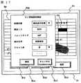
第17図は、上記装置が表示するセル情報設定画面の別の例を示す図である。
第18図は、セルフオーダーシステムを構成するサーバに記憶される注文管理情報の例を示す図である。
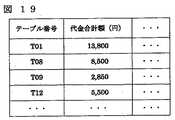
第19図は、セルフオーダーシステムを構成するサーバに記憶される売上管理情報の例を示す図である。
第20図は、セルフオーダーシステムを構成するサーバに記憶される商品情報の例を示す図である。
第21図は、上記セルフオーダーシステムを構成するセルフオーダー端末のブロック構成図である。FIG. 1 is a block diagram showing an embodiment of a screen information editing apparatus according to the present invention.
FIG. 2 is a diagram showing an example of a screen displayed on an information processing terminal that operates based on screen information edited by the device.
FIG. 3 is a diagram showing another example of a screen displayed on the information processing terminal that operates based on the screen information edited by the apparatus.
FIG. 4 is a diagram showing still another example of the screen displayed on the information processing terminal operating based on the screen information edited by the device.
FIG. 5 is a diagram showing an example of screen information edited by the above apparatus.
FIG. 6 is a diagram showing an example of an image file constituting the screen of FIG.
FIG. 7 is a diagram showing an example of an image file constituting the screen of FIG.
FIG. 8 is a diagram showing an example of an image file constituting the screen of FIG.
FIG. 9 is a flowchart showing an embodiment of the screen information editing method according to the present invention executed by the apparatus.
FIG. 10 is a diagram showing an example of a layout frame displayed by the apparatus.
FIG. 11 is a diagram showing an example of the cell ID of each cell in the layout frame.
FIG. 12 is a diagram showing the correspondence between each cell in the layout frame and the coordinate value on the display of the information processing terminal.
FIG. 13 is a diagram showing an example of cell position information representing the correspondence relationship of FIG.
FIG. 14 is a diagram showing an example in which the layout frame and the image file are displayed in an overlapping manner.
FIG. 15 is a diagram showing another example in which the layout frame and the image file are displayed in an overlapping manner.
FIG. 16 is a diagram showing an example of a cell information setting screen displayed by the apparatus.
FIG. 17 is a diagram showing another example of the cell information setting screen displayed by the apparatus.
FIG. 18 is a diagram showing an example of order management information stored in a server constituting the self-order system.
FIG. 19 is a diagram showing an example of sales management information stored in a server constituting the self-order system.
FIG. 20 is a diagram showing an example of product information stored in a server constituting the self-order system.
FIG. 21 is a block diagram of a self-order terminal constituting the self-order system.
以下、図面を参照しながら本発明にかかる画面情報の編集装置と編集方法と編集プログラム、記録媒体、情報処理端末の生産方法の実施の形態について説明する。なお、以下に説明する実施の形態は、飲食店のセルフオーダーシステムを構成するセルフオーダー端末に表示される画面に関する画面情報を編集する場合を例とする。
ここで、画面情報とは、セルフオーダー端末に表示される画面ごとの情報であって、各画面のタッチ位置に応じたセルフオーダー端末の処理内容を定義した情報である。また、画面情報の編集とは、画面情報の登録、変更、削除を意味するものとし、より具体的には画面情報に含まれるセル情報の登録、変更、削除を意味する。画面情報やセル情報の具体的な内容については後述する。
図1は、本発明にかかる画面情報編集装置(以下、「本装置」という)の実施の形態を示すブロック図である。本装置10は、セルフオーダーシステムを構成するサーバ20と通信回線を介して接続している。通信回線の例としては、専用線、公衆交換電話網(PSTN)、無線電話網、CATV網、衛星通信網等がある。セルフオーダーシステムについては後述するが、サーバ20のほかに、セルフオーダー端末30、厨房端末40、会計端末50、店員端末60から構成されている。なお、後述するように、本装置10がサーバ20と接続するのは、編集した画面情報を送信する際のみでよい。
本装置は、後述する本発明にかかる画面情報編集方法(以下、「本方法」という)を実行できる情報処理装置であればよく、例えば、パーソナルコンピュータなどを用いることができる。
本装置10では、本発明にかかる画面情報編集プログラム(以下、「本プログラム」という)が動作して本装置10内の各手段を制御することで本方法を実現する。なお、本プログラムを記録したコンピュータ読取可能な記録媒体(以下、「本記録媒体」という)を用いれば、例えば、汎用コンピュータを本装置と同様に機能させることができる。すなわち、汎用コンピュータが本記録媒体から本プログラムを読み取り実行すれば、この汎用コンピュータ上で本方法を実現することができる。
図2〜4は、セルフオーダー端末30のディスプレイ31に表示される画面の例を示す図である。セルフオーダー端末30は、ディスプレイ31上にタッチパネル32を備え、本装置10により編集された画面情報を参照しながら、ディスプレイ31に表示された画面のタッチ位置に応じた処理を実行するように構成されている。
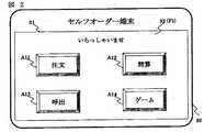
図2は、セルフオーダー端末30の初期画面である。初期画面F1には、客が指でディスプレイ31をタッチすることで、所望の処理を選択することができる4つのエリアA11,A12,A13,A14が表示されている。各エリアには、ボタンを模した図柄と、それぞれ「注文」「精算」「呼出」「ゲー厶」の文字が表示されている。セルフオーダー端末30は、エリアA11がタッチされると「注文処理」、エリアA12がタッチされると「精算処理」、エリアA13がタッチされると「呼出処理」、エリアA14がタッチされると「コンテンツ処理」を実行するように構成されている。各処理の内容について後述する。
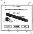
図3は、図2に示す初期画面F1のエリアA11がタッチされたときに表示される商品選択画面F2である。商品選択画面F2には、「ソーセージ」の画像A21、「ビール」の画像A22、「初期画面」の文字列A23が表示されている。セルフオーダー端末30は、画像A21や画像A22、またはその近傍がタッチされると「ソーセージ」または「ビール」の注文確認画面を表示する。また、セルフオーダー端末30は、文字列A23がタッチされると、図2に示す初期画面F1を表示する。
図4は、図3に示す商品選択画面F2の画像A21の近傍がタッチされたときに表示される注文確認画面F3である。注文確認画面F3には、注文商品の商品名欄U31と注文個数欄U32、及び、3つのエリアA31,A32,A33が表示されている。商品名欄U31には、図3の商品選択画面F2で画像A21またはその近傍がタッチされたときには「ソーセージ」の文字列が表示され、画像A22の近傍がタッチされたときには「ビール」の文字列が表示される。また、各エリアには、ボタンを模した図柄と、各図柄には「+」「−」「確定」の文字が表示されている。セルフオーダー端末30は、エリアA31またはA32がタッチされると、注文個数欄U32に表示されている数値を増減するように構成されている。また、セルフオーダー端末30は、エリアA33がタッチされると、注文情報をサーバ20に送信するように構成されている。送信される注文情報には、商品名欄U31に表示されている商品に関する商品IDと、注文個数欄U32に表示されている数値(注文点数)が含まれる。
(本装置について)
本装置10は、図1に示すように、レイアウト設定画面表示手段11,画像表示手段12,セル情報取得手段13,画面情報出力手段14,情報表示手段15,情報入力手段16と,画面情報マスタM1,画像マスタM2,レイアウトマスタM3とを有してなる。情報表示手段15の例としてはディスプレイ,情報入力手段16の例としてはキーボードやマウスがある。
画面情報マスタM1は、本装置10が編集した画面情報を記憶する手段である。画面情報のファイル形式にはCSV形式などがある。図5は、画面情報マスタM1内に記憶されている画面情報の例を示す図である。画面情報には画像ファイルのファイル名とセル情報が含まれる。画像ファイルとは、セルフオーダー端末30のディスプレイ31に表示される画面を構成する電子ファイルである。また、セル情報とは、セルごとの情報であって、画面内でそのセルに相当する位置がタッチされたときのセルフオーダー端末30の処理内容などを含む。
画像マスタM2は、画像ファイルを記憶する手段である。セルフオーダー端末30は、画像マスタM2から画像ファイルを読み出してディスプレイ31に表示する。画像ファイルのファイル形式にはJPEG形式、GIF形式、BMPなどがある。
図6〜8は、画像マスタM2に記憶されている画像ファイルの例である。図6の画像ファイルQ1は図2の初期画面F1に、図7の画像ファイルQ2は図3の商品選択画面F2に、図8の画像ファイルQ3は図4の注文確認画面F3に、それぞれ対応する。ここで、図2の初期画面F1は、画像ファイルQ1がそのまま表示されている。また、図3の商品選択画面F2は、画像ファイルQ2上に「初期画面」の文字が重ねて表示されている。この「初期画面」の文字の表示位置などは、商品選択画面F2の画面情報に定義されている。さらに、図4の注文確認画面F3は、画像ファイルQ3の商品名欄U31に「ソーセージ」の文字、注文個数欄U32に「1」の文字、がそれぞれ挿入されて表示されている。「挿入されて表示」とは、もともと画像ファイルの一部が空欄となっていて、その部分にセルフオーダー端末30内のプログラ厶が所定の文字を表示することを意味する。なお、後述するように、商品名欄U31に挿入される文字は、商品選択画面F2の画面情報に定義されている商品IDをもとに検索されたものである。また、注文個数欄U32に挿入される文字は、注文確認画面F3の画面情報に定義されている。
レイアウトマスタM3は、レイアウト情報を記憶する手段である。レイアウト情報のファイル形式にはCSV形式などがある。レイアウト情報については後述する。
図9は、本方法の実施の形態を示すフローチャートである。
以下、本装置10の操作者(以下、「編集者」という)が図3に示す商品選択画面F2の画面情報を編集する場合を例に、本発明について説明する。
本装置10は、レイアウト設定画面表示手段11を用いて、レイアウトマスタM3からレイアウト情報を読み出し、レイアウト設定画面をディスプレイ15に表示する(S1)。
図10は、ディスプレイ15に表示されたレイアウト設定画面の例を示す図である。レイアウト設定画面P1には、図中太線で示されたレイアウト枠L1が表示されていて、レイアウト枠L1内には96個(縦12個×横8個)のセルが表示されている。セルとは、画面情報の編集単位である。また、レイアウト情報とは、レイアウト枠L1内の各セルのディスプレイ15内での表示の位置と大きさなどを定義している情報であり、例えば、「レイアウト枠の縦方向の長さ」、「レイアウト枠の横方向の長さ」、「縦方向のセルの数」、「横方向のセルの数」などからなる。なお、レイアウトマスタM3には、レイアウト枠の大きさや、ディスプレイ15内でのレイアウト枠内のセルの表示位置や大きさの異なる複数のレイアウト情報が記憶されていて、本装置10は、編集者が選択したレイアウト情報に基づいたレイアウト設定画面をディスプレイ15に表示する。編集者にレイアウト情報を選択させるには、例えば、各レイアウト情報に識別子(「ドリンクオーダー画面用」「中分類商品用」「サブメニュー表示用」など)を付与しておき、ディスプレイ15にレイアウト情報の識別子の一覧を表示して、その中から編集者に選択させるなどの方法がある。
編集者は、レイアウト枠L1をセルフオーダー端末30のディスプレイ31と見立てて、セルごとにその位置がタッチされたときのセルフオーダー端末30の処理内容を編集する。セルフオーダー端末30の処理内容には「画面表示処理」「注文処理」「精算処理」「呼出処理」「コンテンツ処理」などがある。
なお、レイアウト設定画面P1には、レイアウト枠L1の他に、画面情報を編集する際にマウスなどで選択可能なボタンB11,B12,B13が表示されている。各ボタンが選択されたときの本装置10の動作については後述する。
レイアウト枠L1内の各セルにはセルIDが付与されている。図11は、セルIDの例を示す図であり、セルIDが行番号と列番号の組合せで構成されていることを示している。すなわち、例えば、3行目で7列目に位置するセルのセルIDは(3,7)である。
図12は、本装置10のディスプレイ15に表示されるレイアウト枠L1内のセルと、セルフオーダー端末30のディスプレイ31上の座標値との対応関係を示した図である。例えば、セルID(1,1)のセルと、ディスプレイ31上の位置情報(X座標値,Y座標値)との対応関係は
X0≦X座標値<X1,Y0≦Y座標値<Y1
であることを示している。ここで、座標値(X0,Y0),(X1,Y1)は、それぞれセルID(1,1)の始点座標値,終点座標値という。
図13は、セルフオーダー端末30が備えるセル位置情報記憶手段に記憶されているセル位置情報の例を示す図である。セル位置情報は、レイアウト枠L1内の各セルの始点座標値と終点座標値とを含む。セルフオーダー端末30は、後述するように、ディスプレイ31のタッチ位置を特定した上で、タッチ位置の位置情報(X座標値,Y座標値)をもとにセル情報を検索して処理内容を特定するように構成されている。すなわち、例えば、ディスプレイ31のタッチ位置の位置情報(X座標値,Y座標値)が、
X0≦X座標値<X1,Y0≦Y座標値<Y1 (判定式1)
の関係を満たすとき、セルフオーダー端末30は、セル位置情報記憶手段を参照してセルID(1,1)を特定し、セルID(1,1)のセル情報を検索する。
ただし、セルフオーダー端末30がセルID(1,1)に設定されている処理内容を実行する際のタッチ位置の判定式は、判定式1に代えて、判定式2〜6などを用いるようにしてもよい。
X0<X座標値≦X1,Y0<Y座標値≦Y1 (判定式2)
X0≦X座標値≦X1,Y0≦Y座標値≦Y1 (判定式3)
X0<X座標値<X1,Y0<Y座標値<Y1 (判定式4)
X0≦X座標値<X1,Y0<Y座標値≦Y1 (判定式5)
X0<X座標値≦X1,Y0≦Y座標値<Y1 (判定式6)
なお、図10に示すレイアウト枠L1に含まれる96個のすべてのセルは、形状、模様、色彩および大きさのいずれもが同一であるが、本発明においてはレイアウト枠内の各セルの形態(形状、模様、色彩、大きさ)が同一である必要はない。すなわち、例えば、レイアウト枠内に3つのセルが含まれているときに、3つのセルの形態が互いに異なるものであってもよいし、あるいは、2つのセルの形態が同一で残りの1つのセルの形態のみが異なるものであってもよい。
また、図10に示すレイアウト枠L1に含まれる96個のセルはすべて隙間なく並べて配置されているが、レイアウト枠内のセル同士が間隔を空けて配置されていてもよい。
図9に戻る。
本装置10は、画像表示手段12を用いて、レイアウト枠に画像ファイルを重ねてディスプレイ15に表示する。すなわち、先ず、本装置10は、編集者が選択した図7に示す画像ファイルQ2を画像マスタM2から読み出す(S2)。編集者に画像ファイルQ2を選択させるには、例えば、本装置10が画像マスタM2に記憶されている画像ファイルのファイル名の一覧をディスプレイ15上に表示して、編集者に所望のファイル名を選択させるなどの方法がある。画像ファイルのファイル名は、本装置10内のファイル名記憶手段(図示省略)に記憶される。
次に、本装置10は、読み出した画像ファイルQ2をレイアウト枠L1に重ねて表示する(S3)。
ここで、「レイアウト枠L1に画像ファイルQ2を重ねてディスプレイ15に表示する」とは、編集者がセルディスプレイ15に表示されている画像ファイルQ2を見ながらレイアウト枠L1内の所望のセルを選択してセル情報を入力することができるように、レイアウト枠L1と画像ファイルQ2を表示することを意味する。
なお、「レイアウト設定画面P1と画像ファイルQ2を重ねて表示する」には、例えば、図14に示すように画像ファイルQ2上にレイアウト枠L1内の各セルの境界線を編集者が視認可能となるように表示する方法がある。また、別の表示方法としては、図15に示すように、マウス16により表示位置の移動可能なカーソルRを画像ファイルQ2上に表示させ、レイアウト枠L1内のセルのうちカーソルRの位置のセルCを編集者が視認可能となるように表示する方法がある。
また、本装置10は、図示しない手段を用いて、レイアウト設定画面P1と画像ファイルQ2を重ねて表示させた際に、セル情報が入力済のセル(つまり、セル情報記憶手段にセル情報が記憶されているセル)と未入力のセル(つまり、セル情報記憶手段にセル情報が記憶されていないセル)のディスプレイ15上での表示形態を異なるように表示させてもよい。すなわち、例えば、入力済のセルの色と、未入力のセルの色を変えて表示することで、編集者に未入力のセルを容易に特定させることができる。
なお、レイアウト設定画面P1と画像ファイルQ2を重ねて表示するのに、図9中のS1とS2の処理の順序を逆にして、画像ファイルQ2を取得してディスプレイ15に表示させた後にレイアウト設定画面P1をディスプレイ15に表示させてもよい。
また、図14は、画像ファイルQ2の大きさとレイアウト枠Llの大きさが一致している、つまり、画像ファイルQ2の全体がレイアウト枠L1内に収まっている例を示している。しかし、本発明においては、必ずしも画像ファイルとレイアウト枠の大きさが一致する必要はない。すなわち、例えば、レイアウト枠内には画像ファイルの一部のみが表示されるものであってもよいし、あるいは、レイアウト枠内の一部に画像ファイルが表示されるものであってもよい。
ここで、図14は、説明の便宜上、レイアウト枠Ll内の各セルの大きさとディスプレイ15の大きさの比率は、大きめに記載している。レイアウト枠内のセルは画面情報の編集単位であるから、レイアウト枠内のセルが小さいほど、より詳細なセルフオーダー端末30の処理内容を定義することができる。
図9に戻る。
本装置10は、セル情報取得手段13を用いて、セル情報を取得し、画面情報マスタM1に記憶する(S4)。
ここで、本装置10がセル情報を取得する方法について説明する。
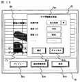
本装置10は、編集者がセルを選択する(例えば、編集者がマウス16で所望のセルを選択して右クリックをする)と、選択されたセルIDを本装置10内のセル情報記憶手段(図示省略)に記憶した上で、セル情報を編集するためのセル情報設定画面をディスプレイ15に表示する。図16,図17はセル情報設定画面の例を示す図である。編集者は、セル情報設定画面に処理内容を入力(選択)することができるほか、処理内容に応じた情報も入力することができる。
編集者は、レイアウト設定画面P1を用いてセル情報を入力する。すなわち、例えば、図14に示すレイアウト枠L1と画像ファイルQ2の例であれば、編集者は、キーボードやマウスなどを用いて、レイアウト枠L1内のセルのうち、画像ファイルQ2内の「ソーセージ」の画像と重なるセルを選択してセル情報を入力する。
図16は、セルC1のセル情報として、処理内容「注文処理」、商品ID「G02」、画面ID「M30」などが入力されていることを示している。すなわち、このセル情報によれば、セルフオーダー端末30は、ディスプレイ31に表示された画像ファイルQ2のセルC1に相当する範囲がタッチされたとき、画面ID「M30」の画面を表示すると共に、商品ID「G02」の注文処理を行う。注文処理については後述する。
また、図17は、セルC2のセル情報として、処理内容「画面表示処理」、画面ID「M00」、フォントサイズ「24P」、表示文字「初期画面」、テキスト枠「有」などが入力されていることを示している。すなわち、このセル情報によれば、セルフオーダー端末30は、画像ファイルQ2をディスプレイ31に表示する際に、セルC2に相当する位置に文字「初期画面」をテキスト枠付きでフォントサイズ「24P」で表示する。また、セルフオーダー端末30は、ディスプレイ31に表示された画像ファイルQ2のセルC2に相当する範囲がタッチされたとき、画面ID「M00」の画面をディスプレイ31に表示する。
なお、ディスプレイ15上で編集者がセルを選択したとき、選択されたセルと選択されていないセルとを識別可能とするために、選択されたセルの形態、例えば色を変化させて表示させてもよい。
編集者がセル情報を入力した後にセル情報設定画面P2内の「確定」ボタンB22を選択する、つまりマウス16でクリックすると、セル情報設定画面P2の表示が消え、ディスプレイ15にはレイアウト設定画面P1のみが表示された状態に戻る。その際、セル情報設定画面P2内に入力されたセル情報は、先に記憶されていたセルIDと共にセル情報記憶手段に記憶される。ここで、編集者がレイアウト設定画面P1内の「確定」ボタンB13を選択すると、セル情報記憶手段に記憶されているセル情報から画面情報が生成されて画面情報マスタM1に記憶される。
図5に示すように、画面情報には、画面を特定する画面IDと、その画面の画像ファイルのファイル名と、セル情報などが含まれる。また、セル情報には、セルID、処理内容、商品ID、画面ID、コンテンツID、テキスト、などが含まれる。なお、画面情報に含まれる画面IDは、例えば、本装置10がレイアウト設定画面P1をディスプレイ15に表示する際に、編集者がキーボード16などを用いて指定できるようにしておくとよい。編集者が指定した画面IDは、本装置10内の画面ID記憶手段(図示省略)に記憶される。
レイアウト設定画面P1の「確定」ボタンB13が選択されると、セル情報記憶手段に記憶されているセル情報から画面情報が生成されて、画面情報マスタM1に記憶される。生成される画面情報には、前述のファイル名記憶手段内のファイル名と、画面ID記憶手段内の画面IDとが含まれる。
なお、セル情報設定画面P2の「確定」ボタンB14が選択されてレイアウト設定画面P1がディスプレイ15に表示されている状態で「プレビュー」ボタンB11が選択されると、本装置10は、セル情報記憶手段に記憶されているセル情報に基づいてディスプレイ15に編集中の画面を表示する。例えば、図15に示したセル情報の入力後に「プレビュー」ボタンB11が選択されたとき、本装置10は、画像ファイルQ2に文字列「初期画面」を重ねてディスプレイ15に表示する。編集者は、プレビュー画面を閲覧することで、セル情報として入力された文字列と画像ファイルとの位置関係などを確かめることができる。
また、レイアウト設定画面P1内のセルが選択された状態で「設定情報削除」ボタンB12が選択されると、選択されたセルに関するセル情報がセル情報記憶手段から削除される。
なお、レイアウト枠内のセルの大きさが小さいほど、セルフオーダー端末30に表示される画面内のタッチ位置によるセルフオーダー端末30の処理内容を細かく定義することができる。その一方で、レイアウト枠内のセルの数が多くなると、セル情報の編集作業の負担は大きくなる。
そこで、本装置10は、セル情報の複写機能を備えていてもよい。セル情報の複写機能とは、セル情報記憶手段に記憶されているセルのセル情報を、別のセルのセル情報としてセル情報記憶手段に記憶する機能である。すなわち、例えば、図5は、画面ID「M20」のセルID(7,4)、(8,4)、(8,5)のセル情報がセルID(7,3)のセル情報と同一であることを示している。つまり、これら4つのセルの位置がタッチされたときのセルフオーダー端末30の処理内容が同一であることを意味する。編集者は、これら4つのセルのセル情報として同一の内容を入力する必要がある。このような場合に、以下に説明するセル情報の複写機能を利用すれば、編集作業の効率を上げることができる。
本装置10は、セル情報複写手段(図示省略)により、編集者に入力済のセルID(7,3)のセルを複写元のセル、未入力または入力済のセルID(7,4)、(8,4)、(8,5)を複写先のセルとして指定させる。編集者に複写元と複写先のセルを指定させるには、画像ファイルとレイアウト枠が重ねて表示された状態で、レイアウト枠内のセルをマウス16でクリックさせて選択させる方法などがある。
前述のとおり入力済のセル情報は、セル情報記憶手段に記憶されている。本装置10は、セル情報複写手段により、セル情報記憶手段に記憶されている複写元のセルID(7,3)のセル情報を、複写先のセルID(7,4)、(8,4)、(8,5)のセル情報としてセル情報記憶手段に記憶する。
本装置10は、前述のとおり、編集者がレイアウト設定画面P1内の「確定」ボタンB13を選択すると、セル情報記憶手段内のセル情報から画面情報を生成して画面情報マスタM1に記憶する。
このセル情報の複写機能によれば、レイアウト枠内の複数のセルに同一のセル情報を入力する場合の、編集作業ミスの回避、編集作業の労力軽減、編集作業時間の短縮化、などを図ることができる。
図9に戻る。
本装置10は、画面情報出力手段14を用いて、画面情報マスタM1に記憶されている画面情報を出力する(S5)。図1は、本装置10が画面情報マスタM1内に記憶されている画面情報をサーバ20に送信する例を示している。サーバ20は、後述するように、本装置10から受信した画面情報をセルフオーダー端末30に送信する。ただし、本装置10は、サーバ20を介さずに、直接セルフオーダー端末30に画面情報を送信するようにしてもよい。
なお、本装置10による画面情報の出力の態様には、通信回線を介して別の情報処理装置に送信する他、CD−ROMなどの本装置10の外部記憶装置に記憶するなどがある。この場合、セルフオーダー端末30あるいはサーバ20は、外部記憶装置から画面情報を読み出して記憶する。
以上説明したように、本装置10は、レイアウト枠L1に画像ファイルQ2を重ねて表示した上で、レイアウト枠L1内の各セルのセル情報を取得する構成としている。この構成によれば、編集者は、セルフオーダー端末30のディスプレイ31に実際に表示される画像ファイルを閲覧しながら、その画像ファイルのタッチ位置ごとにセルフオーダー端末30の処理内容を定義することができる。すなわち、本発明によれば、1の画像ファイルに対して複数の処理内容を含む画面情報を編集することができ、例えば、セルフオーダー端末30に表示された画面が1の画像ファイルで構成されていても、その画像ファイルのタッチ位置に応じて異なる処理をセルフオーダー端末30に実行させる画面情報を編集することができる。
以下、本装置10により編集された画面情報とセルフオーダーシステムとの関係について説明する。
(セルフオーダーシステムについて)
セルフオーダーシステムは、図1に示すように、セルフオーダー端末30,厨房端末40,会計端末50、店員端末60が通信回線を介してサーバ20と接続している。セルフオーダー端末30は、サーバ20を介して厨房端末40、会計端末50、店員端末60と情報の送受信が可能となるように構成されている。
(サーバについて)
サーバ20は、セルフオーダーシステム全体の情報処理を管理する情報処理装置であって、注文管理情報データベースDB21,売上管理情報データベースDB22,画面情報マスタM21,画像マスタM22,コンテンツマスタM23,商品マスタM24を備える。サーバ20は、セルフオーダー端末30と、厨房端末40や会計端末50との間の情報交換を実現できる装置であればよく、例えば、パーソナルコンピュータなどで実現されている。
注文管理情報データベースDB21は、店内のセルフオーダー端末ごと、つまり店内のテーブルごとの注文情報を記憶するデータベースである。注文情報には、例えば、客が注文した商品を特定する商品ID、注文点数、注文時刻や、注文した商品ごとの調理状況や配膳完了の有無に関する情報が含まれる。
図18は、注文管理情報データベースDB21に記憶されている注文情報の例を示す図である。例えば、図中1行目は、テーブル番号「T01」から商品ID「G21」の商品が「4」点、2005年3月8日17時05分に注文され、テーブルへの配膳も完了していることを示している。
売上管理情報データベースDB22は、セルフオーダー端末ごとの売上情報を記憶するデータベースである。売上情報には、代金合計額などが含まれる。図19は、売上管理情報データベースDB22に記憶されている売上情報の例を示す図であり、例えば、テーブル番号「T01」の代金合計額が「13,800円」であることを示している。
商品マスタM24は、セルフオーダー端末30で注文可能な商品ごとの商品情報を記憶している手段である。商品情報には、商品名や単価などが含まれる。図20は、商品マスタM24に記憶されている商品情報の例を示す図であり、例えば、商品ID「G01」は、商品名が「ソーセージ」で単価が「800円」であることなどを示している。
なお、図19に示す代金合計額は、図18に示した注文管理情報データベースDB21に記憶されているテーブル番号ごとの注文情報に含まれる商品IDと注文点数、並びに商品マスタM24に記憶されている単価から算出されている。
画面情報マスタM21は、本装置10で編集された画面情報を記憶する手段である。画像マスタM22は、セルフオーダー端末30のディスプレイ31に表示される画像ファイルを記憶する手段である。コンテンツマスタM23は、セルフオーダー端末30に表示されるコンテンツを記憶する手段である。コンテンツとは、画像(静止画、動画)、音声、テキストなどの電子情報である。また、コンテンツの内容には、例えば、店舗や商品などの宣伝(コマーシャル:CM)、ゲーム、占いなどがある。各コンテンツにはコンテンツIDが付与されている。コンテンツIDの例としては、コンテンツの電子情報のファイル名などがある。
(厨房端末について)
厨房端末40は、店内の厨房に設置された情報処理端末であって、客がセルフオーダー端末30を操作して商品を注文すると、その注文内容、例えば、商品名と注文個数がテーブル番号と共に表示されるように構成されている。
(会計端末について)
会計端末50は、店内のレジ端末であって、客がセルフオーダー端末30を操作して注文した商品の代金を表示するように構成されている。
(店員端末について)
店員端末60は、店員が操作する情報処理端末であって、客がセルフオーダー端末30を操作して店員の呼出を行うと、テーブル番号と共に客が呼んでいる旨が表示される。また、店員は、調理済みの料理を厨房からテーブルに配膳後、店員端末60を操作してその旨をサーバ20に送信する。
(セルフオーダー端末について)
セルフオーダー端末30は、客自身が操作する情報処理端末であって、店内のテーブルごとに配置されている。セルフオーダー端末30は、テーブル番号を記憶するためのテーブル番号記憶手段(図示省略)を有してなる。セルフオーダー端末30は、例えば、テーブルごとに設けられた置き台にセルフオーダー端末30がセットされた際に、あらかじめ置き台に設定されているテーブル番号を読み取り、テーブル番号記憶手段に記憶する。置き台に設定されているテーブル番号は、店内のテーブルごとに異なる番号である。セルフオーダー端末30からサーバ20に送信される通信データには、テーブル番号が含まれていて、サーバ20は、受信した通信データに含まれるテーブル番号を読み取ることで、どのテーブルからの通信データであるかを特定することができる。
図21は、セルフオーダー端末30のブロック構成図である。セルフオーダー端末30は、ディスプレイ31、タッチパネル32、タッチパネル制御部33、表示処理部34、画面制御部35、注文処理部36、精算処理部37、呼出処理部38と、画面情報マスタM31、画像マスタM32、コンテンツマスタM33、商品マスタM34、注文情報データベースDB31の各手段を有してなる。
画面情報マスタM31は、本装置10により編集された画面情報を記憶する手段である。画像マスタM32は、画像ファイルを記憶する手段である。コンテンツマスタM33は、コンテンツを記憶する手段である。また、注文情報データベースDB31は、セルフオーダー端末30が生成した注文情報を記憶する手段である。
セルフオーダー端末30は、電源が入力されると図示しない手段を用いて、各マスタM31,M32,M33,M34内に記憶する情報の要求情報をサーバ20に送信する。要求情報を受信したサーバ20は、各マスタM21,M22,M23,M24内の情報をセルフオーダー端末30に送信する。セルフオーダー端末30は、サーバ20から受信した情報を各マスタM31,M32,M33,M34に記憶する。
なお、サーバ20が各マスタ内の情報をセルフオーダー端末30に送信するのは、セルフオーダー端末30から要求情報を受信した場合に限らない。すなわち、例えば、サーバ20のマスタ内の情報が更新された際に、セルフオーダー端末30からの要求情報を受信することなく、サーバ20が更新された情報のみまたはマスタ内の全部の情報をセルフオーダー端末30に送信するようにしてもよい。
以下、図2〜4に示した画面例を参照しながら、ディスプレイ31がタッチされたときにセルフオーダー端末30が実行する「画面表示処理」「注文処理」「精算処理」「呼出処理」「コンテンツ処理」の各処理について説明する。ここで、図2の初期画面F1の画面IDは「M10」、図3の商品選択画面F2の画面IDは「M20」、図4の注文確認画面F3の画面IDは「M30」とする。また、図6の画像ファイルQ1のファイル名は「Top.jpg」、図7の画像ファイルQ2のファイル名は「Sausage.jpg」、図8の画像ファイルQ3のファイル名は「Order.jpg」とする。
なお、セルフオーダー端末30は、ディスプレイ31がタッチされたとき、タッチパネル32がタッチ位置を検出して、検出情報をタッチパネル制御部33に通知する。タッチ位置の検出方式には、抵抗膜方式(アナログ抵抗膜方式)、超音波表面弾性波方式、赤外線遮光方式、静電容量方式、電磁誘導方式などがある。タッチパネル制御部33は、タッチパネル32から通知された検出情報に基づいてタッチ位置の位置情報(X座標値とY座標値)を特定し、画面制御部35に通知する。画面制御部35は、図13に示した始点および終点の座標値とセルIDとの対応表を参照して、タッチパネル制御部33から通知された位置情報に対応するセルIDを特定する。さらに、画面制御部35は、画面ID記憶手段に記憶されている画面1Dと特定したセルIDに対応するセル情報を、画面マスタM32から検索する。そして、画面制御部35は、検索されたセル情報から処理内容を特定して各処理部に処理依頼を通知する。
(画面表示処理について)
図2に示す初期画面F1のエリアA11がタッチされると、画面制御部35は、画面情報マスタM31内の初期画面F1の画面情報を参照して、タッチ位置に相当するセルのセル情報を検索する。ここでは、処理内容「画面表示処理」や画面ID「M20」などが検索されたとする。画面制御部35は、検索された画面ID「M20」の画面情報を参照して、画像ファイルのファイル名「Sausage.jpg」を画面情報マスタM31から検索する。さらに、画面制御部35は、検索されたファイル名「Sausage.jpg」の画像ファイルQ2を画像マスタM32から検索して、表示処理部34に通知する。表示処理部34は、画面制御部35から通知された画像ファイルQ2をディスプレイ31に表示する。ディスプレイ31には、図3に示した商品選択画面F2が表示される。
(注文処理について)
図3に示す商品選択画面F2の画像A21がタッチされると、画面制御部35は、画面情報マスタM31内の商品選択画面F2の画面情報を参照して、タッチ位置に相当するセルのセル情報を検索する。ここでは、処理内容「注文処理」、商品ID「G01」、画面ID「M30」などが検索されたとする。画面制御部35は、検索された商品ID「G01」に対応する商品名「ソーセージ」を商品マスタM34から検索する。また、画面制御部35は、検索された画面ID「M30」の画面情報を参照して、画像ファイルのファイル名「Order.jpg」を画面情報マスタM31から検索し、画像マスタM32から画像ファイルQ3を検索する。さらに、画面制御部35は、検索された商品名「ソーセージ」と画像ファイルQ3、並びに注文個数「1」を表示処理部34に通知する。このとき、画面制御部35は、商品名「ソーセージ」と注文個数「1」を注文情報記憶手段(図示省略)に記憶しておく。表示処理部34は、画像ファイルQ3、商品名「ソーセージ」、注文個数「1」をディスプレイ31に表示する。ディスプレイ31には、図4に示した注文確認画面F3が表示される。なお、注文個数「1」は、注文確認画面F3の画面情報に定義されているものとする。
客は、注文確認画面F3を閲覧して注文内容を確認する。その際、注文個数を変更することができる。例えば、客が注文確認画面F3のエリアA31をタッチすると、画面制御部35は、注文確認画面F3の画面情報のエリアA31に相当するセルのセル情報に基づいて、注文情報記憶手段に記憶されている注文個数「1」を「2」に更新すると共に、注文個数「2」を表示処理部34に通知する。表示処理部34は、注文個数欄U32に「2」を表示する。
客が注文確認画面F3のエリアA33をタッチすると、画面制御部35は、注文確認画面F3の画面情報のエリアA33に相当するセル情報に基づいて、注文情報記憶手段に記憶されている商品名と注文個数からなる注文情報を注文処理部36に通知する。注文処理部36は、注文情報を注文情報データベースDB31に記憶する。また、注文処理部36は、注文情報をテーブル番号記憶部に記憶されているテーブル番号と共にサーバ20に送信する。
サーバ20は、受信した注文情報を注文管理情報データベースDB21に記憶すると共に、厨房端末40に送信する。また、サーバ20は、注文情報から代金合計額を算出し、売上管理情報データベースDB22に記憶する。
厨房の料理人は、厨房端末40に表示された注文情報を見て調理をする。なお、料理人が、厨房端末40に表示された注文情報の中から調理を開始する料理を選択すると、調理の開始が厨房端末40からサーバ20に通知され、注文管理情報データベースDB21内の調理状況が「未調理」から「調理中」に更新される。また、調理が完了した際にもその旨が厨房端末40からサーバ20に送信され、注文管理情報データベースDB21内の調理状況が「調理中」から「調理済」に更新されると共に、配膳状況も「未配膳」から「配膳待」に更新される。店員は、調理済の商品(料理)を配膳して店員端末60を操作すると、配膳が完了した旨が店員端末60からサーバ20に送信され、注文管理情報データベースDB21内の配膳状況が「配膳待」から「配膳済」に更新される。
(精算処理について)
図2に示す初期画面F1のエリアA12がタッチされると、画面制御部35は、画面情報マスタM31内の初期画面F1の画面情報を参照して、タッチ位置に相当するセルのセル情報を検索する。ここでは、処理内容「精算処理」が検索されたとする。画面制御部35は、精算処理部37に処理依頼を通知する。精算処理部37は、テーブル番号記憶手段に記憶されているテーブル番号を含む精算依頼情報をサーバ20に送信する。
サーバ20は、受信した精算依頼情報に含まれるテーブル番号をもとに売上管理情報データベースDB22を検索して代金合計額を読み出し、会計端末50に送信する。会計端末のディスプレイには、サーバ20から受信した代金合計額が表示され、店員は会計端末50に表示された代金を客から受取る。
(呼出処理について)
図2の初期画面F1のエリアA13がタッチされると、画面制御部35は、画面情報マスタM31内の初期画面F1の画面情報を参照して、タッチ位置に相当するセルのセル情報を検索する。ここでは、処理内容「呼出処理」が検索されたとする。画面制御部35は、呼出処理部38に処理依頼を通知する。呼出処理部38は、テーブル番号記憶手段に記憶されているテーブル番号を含む呼出依頼情報をサーバ20に送信する。
サーバ20は、受信した呼出依頼情報に含まれるテーブル番号を店員端末60に送信する。店員端末60は、そのディスプレイにテーブル番号を表示させて、客が呼んでいる旨を店員に通知する。
(コンテンツ処理について)
図2の初期画面F1のエリアA14がタッチされると、画面制御部35は、画面情報マスタM31内の初期画面F1の画面情報を参照して、タッチ位置に相当するセルのセル情報を検索する。ここでは、処理内容「コンテンツ処理」とコンテンツIDが検索されたとする。画面制御部35は、検索されたコンテンツIDに対応するコンテンツをコンテンツマスタM33から検索して、表示処理部34に通知する。表示処理部34は、通知されたコンテンツをディスプレイ31に表示する。
このように、セルフオーダー端末30は、本装置10により編集された画面情報を参照しながら、ディスプレイ31に画面やコンテンツを表示し、また、ディスプレイ31がタッチされたときにタッチ位置に応じた処理を実行する。セルフオーダーシステムは、セルフオーダー端末30がタッチ位置に応じた処理により生成した各種情報を、サーバ20を介して、厨房端末40,会計端末50,店員端末60に送信する。
なお、以上説明した実施の形態では、セルフオーダー端末30に表示される画面の画面情報を編集する場合を例としたが、厨房端末40,会計端末50,店員端末60などに表示される画面の画面情報を編集する場合にも本発明は適用可能である。
産業上の利用の可能性
本発明は、セルフオーダーシステムを構成する端末の他に、飲料水やタバコなどの自動販売機、鉄道や航空機などのチケット販売機、あるいは、いわゆるKIOSK端末など、タッチパネルを備えた情報処理端末に表示される画面の画面情報の編集に適用することができる。Hereinafter, embodiments of a screen information editing apparatus, editing method, editing program, recording medium, and information processing terminal production method according to the present invention will be described with reference to the drawings. In addition, embodiment described below makes the example the case where the screen information regarding the screen displayed on the self-order terminal which comprises the self-order system of a restaurant is edited.
Here, the screen information is information for each screen displayed on the self-order terminal, and is information defining processing contents of the self-order terminal corresponding to the touch position of each screen. The editing of screen information means registration, change, and deletion of screen information, and more specifically, registration, change, and deletion of cell information included in the screen information. Specific contents of the screen information and cell information will be described later.
FIG. 1 is a block diagram showing an embodiment of a screen information editing apparatus (hereinafter referred to as “this apparatus”) according to the present invention. The
The apparatus may be any information processing apparatus that can execute a screen information editing method (hereinafter referred to as “the present method”) according to the present invention, which will be described later. For example, a personal computer or the like can be used.
In this
2 to 4 are diagrams illustrating examples of screens displayed on the
FIG. 2 is an initial screen of the self-
FIG. 3 is a product selection screen F2 displayed when the area A11 of the initial screen F1 shown in FIG. 2 is touched. On the product selection screen F2, an image A21 of “sausage”, an image A22 of “beer”, and a character string A23 of “initial screen” are displayed. When the image A21 or the image A22 or its vicinity is touched, the self-
FIG. 4 is an order confirmation screen F3 displayed when the vicinity of the image A21 on the product selection screen F2 shown in FIG. 3 is touched. On the order confirmation screen F3, a product name column U31 and an order quantity column U32 of the ordered product and three areas A31, A32, A33 are displayed. In the product name column U31, a character string “sausage” is displayed when the image A21 or its vicinity is touched on the product selection screen F2 of FIG. 3, and a character string “beer” is displayed when the vicinity of the image A22 is touched. Is displayed. In each area, a symbol imitating a button and characters “+”, “−”, and “confirm” are displayed in each symbol. The self-
(About this device)
As shown in FIG. 1, the
The screen information master M1 is means for storing screen information edited by the
The image master M2 is a means for storing an image file. The self-
6 to 8 are examples of image files stored in the image master M2. 6 corresponds to the initial screen F1 in FIG. 2, the image file Q2 in FIG. 7 corresponds to the product selection screen F2 in FIG. 3, and the image file Q3 in FIG. 8 corresponds to the order confirmation screen F3 in FIG. . Here, the image file Q1 is displayed as it is on the initial screen F1 of FIG. In the product selection screen F2 in FIG. 3, the characters “initial screen” are superimposed on the image file Q2. The display position of the characters of the “initial screen” is defined in the screen information of the product selection screen F2. Further, the order confirmation screen F3 of FIG. 4 is displayed with the characters “sausage” inserted in the product name column U31 and the characters “1” inserted in the order quantity column U32 of the image file Q3. “Insert and display” means that a part of the image file is originally blank and the program in the self-
The layout master M3 is a means for storing layout information. The layout information file format includes a CSV format. The layout information will be described later.
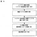
FIG. 9 is a flowchart showing an embodiment of the present method.
Hereinafter, the present invention will be described by taking as an example a case where an operator of the apparatus 10 (hereinafter referred to as “editor”) edits the screen information of the product selection screen F2 shown in FIG.
The
FIG. 10 is a diagram illustrating an example of a layout setting screen displayed on the
The editor views the layout frame L1 as the
In addition to the layout frame L1, buttons B11, B12, and B13 that can be selected with a mouse or the like when editing screen information are displayed on the layout setting screen P1. The operation of the
A cell ID is assigned to each cell in the layout frame L1. FIG. 11 is a diagram showing an example of a cell ID, and shows that the cell ID is composed of a combination of a row number and a column number. That is, for example, the cell ID of the cell located in the third row and the seventh column is (3, 7).
FIG. 12 is a diagram showing a correspondence relationship between the cells in the layout frame L1 displayed on the
X0 ≦ X coordinate value <X1, Y0 ≦ Y coordinate value <Y1
It is shown that. Here, the coordinate values (X0, Y0) and (X1, Y1) are referred to as the start point coordinate value and the end point coordinate value of the cell ID (1, 1), respectively.
FIG. 13 is a diagram illustrating an example of the cell position information stored in the cell position information storage unit included in the self-
X0 ≦ X coordinate value <X1, Y0 ≦ Y coordinate value <Y1 (judgment formula 1)
When the relationship is satisfied, the self-
However, the determination formula of the touch position when the self-
X0 <X coordinate value ≦ X1, Y0 <Y coordinate value ≦ Y1 (judgment formula 2)
X0 ≦ X coordinate value ≦ X1, Y0 ≦ Y coordinate value ≦ Y1 (judgment formula 3)
X0 <X coordinate value <X1, Y0 <Y coordinate value <Y1 (judgment formula 4)
X0 ≦ X coordinate value <X1, Y0 <Y coordinate value ≦ Y1 (judgment formula 5)
X0 <X coordinate value ≦ X1, Y0 ≦ Y coordinate value <Y1 (judgment formula 6)
Although all the 96 cells included in the layout frame L1 shown in FIG. 10 have the same shape, pattern, color, and size, in the present invention, the form of each cell in the layout frame ( (Shape, pattern, color, size) need not be the same. That is, for example, when three cells are included in the layout frame, the three cells may have different forms, or the two cells have the same form and the remaining one cell. Only the form may be different.
Further, although the 96 cells included in the layout frame L1 shown in FIG. 10 are all arranged side by side without a gap, the cells in the layout frame may be arranged with an interval between them.
Returning to FIG.
The
Next, the
Here, “the image file Q2 is superimposed on the layout frame L1 and displayed on the
Note that “display the layout setting screen P1 and the image file Q2 in an overlapping manner” indicates that, for example, the editor can visually recognize the boundary line of each cell in the layout frame L1 on the image file Q2 as shown in FIG. There is a way to display as follows. As another display method, as shown in FIG. 15, a cursor R whose display position can be moved by the mouse 16 is displayed on the image file Q2, and the cell at the position of the cursor R among the cells in the layout frame L1. There is a method of displaying C so that the editor can see it.
In addition, when the layout setting screen P1 and the image file Q2 are displayed in an overlapped manner using a means (not shown), the
In order to display the layout setting screen P1 and the image file Q2 in an overlapping manner, the processing order of S1 and S2 in FIG. 9 is reversed, the image file Q2 is acquired and displayed on the
FIG. 14 shows an example in which the size of the image file Q2 matches the size of the layout frame L1, that is, the entire image file Q2 is within the layout frame L1. However, in the present invention, the size of the image file and the layout frame do not necessarily match. That is, for example, only a part of the image file may be displayed in the layout frame, or the image file may be displayed in a part of the layout frame.
Here, in FIG. 14, for convenience of explanation, the ratio of the size of each cell in the layout frame L1 and the size of the
Returning to FIG.
This
Here, a method in which the
In this
The editor inputs cell information using the layout setting screen P1. That is, for example, in the example of the layout frame L1 and the image file Q2 shown in FIG. 14, the editor uses the keyboard, mouse, or the like to select “sausage” in the image file Q2 among the cells in the layout frame L1. Cell information is input by selecting a cell that overlaps the image of.
FIG. 16 shows that the processing content “order processing”, the product ID “G02”, the screen ID “M30”, and the like are input as the cell information of the cell C1. That is, according to this cell information, when the range corresponding to the cell C1 of the image file Q2 displayed on the
In FIG. 17, as the cell information of the cell C2, the processing content “screen display processing”, the screen ID “M00”, the font size “24P”, the display character “initial screen”, the text frame “present”, and the like are input. It shows that. That is, according to this cell information, when the self-
When the editor selects a cell on the
When the editor inputs the cell information and selects the “confirm” button B22 in the cell information setting screen P2, that is, when clicked with the mouse 16, the display of the cell information setting screen P2 disappears, and the
As shown in FIG. 5, the screen information includes a screen ID for specifying the screen, the file name of the image file of the screen, cell information, and the like. The cell information includes a cell ID, a processing content, a product ID, a screen ID, a content ID, a text, and the like. The screen ID included in the screen information may be specified by the editor using the keyboard 16 or the like when the
When the “confirm” button B13 on the layout setting screen P1 is selected, screen information is generated from the cell information stored in the cell information storage means and stored in the screen information master M1. The generated screen information includes the file name in the aforementioned file name storage means and the screen ID in the screen ID storage means.
When the “preview” button B11 is selected in a state where the “confirm” button B14 on the cell information setting screen P2 is selected and the layout setting screen P1 is displayed on the
Further, when the “setting information deletion” button B12 is selected in a state where a cell in the layout setting screen P1 is selected, cell information regarding the selected cell is deleted from the cell information storage means.
Note that as the size of the cell in the layout frame is smaller, the processing content of the self-
Therefore, the
The
As described above, the input cell information is stored in the cell information storage means. The
As described above, when the editor selects the “confirm” button B13 in the layout setting screen P1, the
According to this cell information copying function, when the same cell information is input to a plurality of cells in the layout frame, the editing error can be avoided, the editing labor can be reduced, and the editing time can be shortened. be able to.
Returning to FIG.
The
Note that the screen information is output by the
As described above, the
Hereinafter, the relationship between the screen information edited by the
(About the self-order system)
In the self-order system, as shown in FIG. 1, a self-
(About the server)
The
The order management information database DB21 is a database that stores order information for each self-order terminal in the store, that is, for each table in the store. The order information includes, for example, information on a product ID for specifying a product ordered by a customer, an order score, an order time, a cooking status for each ordered product, and whether or not a serving is completed.
FIG. 18 is a diagram illustrating an example of order information stored in the order management information database DB21. For example, in the first line in the figure, a product with a product ID “G21” from the table number “T01” is ordered at “4”, 17:05 on March 8, 2005, and distribution to the table is completed. It shows that.
The sales management information database DB22 is a database that stores sales information for each self-order terminal. The sales information includes the total price. FIG. 19 is a diagram illustrating an example of sales information stored in the sales management information database DB22. For example, the total price of the table number “T01” is “13,800 yen”.
The product master M24 is a means for storing product information for each product that can be ordered at the self-
The total price shown in FIG. 19 is stored in the product ID and the order score included in the order information for each table number stored in the order management information database DB21 shown in FIG. 18, and in the product master M24. Calculated from unit price.
The screen information master M21 is means for storing screen information edited by the
(About kitchen terminals)
The
(About accounting terminals)
The
(About clerk terminals)
The
(About self-order terminals)
The self-
FIG. 21 is a block configuration diagram of the self-
The screen information master M31 is means for storing screen information edited by the
When power is input, the self-
Note that the
Hereinafter, referring to the screen examples shown in FIGS. 2 to 4, “screen display process”, “order process”, “settlement process”, “call process”, “content” executed by the self-
In the self-
(About screen display processing)
When the area A11 of the initial screen F1 shown in FIG. 2 is touched, the screen control unit 35 refers to the screen information of the initial screen F1 in the screen information master M31 and searches for cell information of the cell corresponding to the touch position. To do. Here, it is assumed that the processing content “screen display processing”, the screen ID “M20”, and the like are searched. The screen control unit 35 refers to the screen information of the searched screen ID “M20” and searches the screen information master M31 for the file name “Sausage.jpg” of the image file. Further, the screen control unit 35 searches the image master M32 for the image file Q2 having the searched file name “Sausage.jpg” and notifies the
(About order processing)
When the image A21 on the product selection screen F2 shown in FIG. 3 is touched, the screen control unit 35 refers to the screen information on the product selection screen F2 in the screen information master M31, and cell information of the cell corresponding to the touch position. Search for. Here, it is assumed that the processing content “order processing”, product ID “G01”, screen ID “M30”, and the like are searched. The screen control unit 35 searches the product master M34 for the product name “sausage” corresponding to the searched product ID “G01”. Further, the screen control unit 35 refers to the screen information of the retrieved screen ID “M30”, retrieves the file name “Order.jpg” of the image file from the screen information master M31, and retrieves the image file Q3 from the image master M32. Search for. Further, the screen control unit 35 notifies the
The customer views the order confirmation screen F3 and confirms the order contents. At that time, the order quantity can be changed. For example, when the customer touches the area A31 of the order confirmation screen F3, the screen control unit 35 is stored in the order information storage unit based on the cell information of the cell corresponding to the area A31 of the screen information of the order confirmation screen F3. The order quantity “1” is updated to “2”, and the order quantity “2” is notified to the
When the customer touches the area A33 of the order confirmation screen F3, the screen control unit 35, based on the cell information corresponding to the area A33 of the screen information of the order confirmation screen F3, the product name stored in the order information storage means The
The
A cook in the kitchen cooks by looking at the order information displayed on the
(About payment processing)
When the area A12 of the initial screen F1 shown in FIG. 2 is touched, the screen control unit 35 refers to the screen information of the initial screen F1 in the screen information master M31 and searches for cell information of the cell corresponding to the touch position. To do. Here, it is assumed that the processing content “settlement processing” is searched. The screen control unit 35 notifies the settlement processing unit 37 of the processing request. The settlement processing unit 37 transmits settlement request information including the table number stored in the table number storage unit to the
The
(Call processing)
When the area A13 of the initial screen F1 in FIG. 2 is touched, the screen control unit 35 refers to the screen information of the initial screen F1 in the screen information master M31 and searches for cell information of the cell corresponding to the touch position. . Here, it is assumed that the processing content “call processing” is retrieved. The screen control unit 35 notifies the call processing unit 38 of the processing request. The call processing unit 38 transmits call request information including the table number stored in the table number storage unit to the
The
(About content processing)
When the area A14 of the initial screen F1 in FIG. 2 is touched, the screen control unit 35 refers to the screen information of the initial screen F1 in the screen information master M31 and searches for cell information of the cell corresponding to the touch position. . Here, it is assumed that the processing content “content processing” and the content ID are searched. The screen control unit 35 retrieves the content corresponding to the retrieved content ID from the content master M33 and notifies the
As described above, the self-
In the embodiment described above, the screen information displayed on the self-
Industrial applicability
The present invention is displayed on an information processing terminal equipped with a touch panel such as vending machines such as drinking water and cigarettes, ticket vending machines such as railways and airplanes, or so-called KIOSK terminals, in addition to terminals constituting a self-order system. This can be applied to editing the screen information of the screen to be displayed.
Claims (14)
Translated fromJapaneseタッチパネルを備えた情報処理端末に表示される画面ごとの情報であって、この画面のタッチ位置に応じた上記情報処理端末の処理内容を定義する画面情報を記憶するための画面情報マスタと、
上記画面を構成する画像ファイルを記憶している画像マスタと、
上記画面情報の編集単位であるセルを複数備えたレイアウト枠に上記画像マスタ内の画像ファイルを重ねて上記ディスプレイに表示する画像表示手段と、
上記画像ファイルと重ねて表示されているレイアウト枠内のセルのセル情報を上記情報入力手段から取得し、この取得したセル情報から画面情報を生成して上記画面情報マスタに記憶するセル情報取得手段と、
上記取得したセル情報を記憶するセル情報記憶手段と、
レイアウト枠内のセルのうち、上記セル情報記憶手段にセル情報が記憶されているセルのディスプレイ上での表示形態を、上記セル情報記憶手段にセル情報が記憶されていないセルの表示形態と異ならせる手段と、
を有してなることを特徴とする画面情報編集装置。Information input means, display,
A screen information master for storing screen information that defines the processing content of the information processing terminal according to the touch position of the screen, which is information for each screen displayed on the information processing terminal having a touch panel;
An image master storing image files constituting the screen, and
Image display means for displaying the image file in the image master on the display in a layout frame having a plurality of cells as editing units of the screen information;
Cell information acquisition means for acquiring cell information of the cells in the layout frame displayed superimposed on the image file from the information input means, generating screen information from the acquired cell information, and storing it in the screen information master When,
Cell information storage means for storing the acquired cell information;
Of the cells in the layout frame, the display mode of the cell whose cell information is stored in the cell information storage unit is different from the display mode of the cell whose cell information is not stored in the cell information storage unit. Means to
A screen information editing apparatus characterized by comprising:
画像表示手段は、上記レイアウトマスタ内のレイアウト情報に基づいてレイアウト枠をディスプレイに表示する請求項1記載の画面情報編集装置。A layout master that stores layout information that defines the display position and size of each cell in the layout frame;
2. The screen information editing apparatus according to claim 1, wherein the image display means displays a layout frame on a display based on layout information in the layout master.
をさらに備える請求項1記載の画面情報編集装置。The copy source cell and the copy destination cell designated by the information input means are acquired, and the cell information of the designated copy source cell stored in the cell information storage means is stored in the designated copy destination cell. Cell information copying means for storing in the cell information storage means as cell information of the cell;
The screen information editing apparatus according to claim 1, further comprising:
画面情報マスタ内の画面情報を上記通信ネットワークを介して上記情報処理端末に送信する手段をさらに備えた請求項1記載の画面情報編集装置。Connect to the information processing terminal via the communication network,
The screen information editing apparatus according to claim 1, further comprising means for transmitting screen information in a screen information master to the information processing terminal via the communication network.
画面情報マスタ内の画面情報を上記通信ネットワークを介して上記サーバに送信する手段をさらに備えた請求項1記載の画面情報編集装置。Connect to a server that can send data to the information processing terminal via a communication network,
The screen information editing apparatus according to claim 1, further comprising means for transmitting screen information in a screen information master to the server via the communication network.
コンピュータプログラムは請求項8記載の画面情報編集プログラムであることを特徴とするコンピュータ読取可能な記録媒体。A recording medium storing a computer program,
A computer-readable recording medium, wherein the computer program is the screen information editing program according to claim 8.
タッチパネルを備えた情報処理端末に表示される画面ごとの情報であって、この画面のタッチ位置に応じた上記情報処理端末の処理内容を定義する画面情報を記憶するための画面情報マスタと、
上記画面を構成する画像ファイルを記憶している画像マスタと、
上記情報入力手段から取得したセル情報を記憶するセル情報記憶手段と、
を備えた装置により実行される方法であって、
上記装置が、画面情報の編集単位であるセルを複数備えたレイアウト枠に上記画像マスタ内の画像ファイルを重ねて上記ディスプレイに表示するステップと、
上記装置が、上記画像ファイルと重ねて表示されているレイアウト枠内のセルのセル情報を上記情報入力手段から取得し、この取得したセル情報を上記セル情報記憶手段に記憶するステップと、
上記装置が、上記取得したセル情報から画面情報を生成して上記画面情報マスタに記憶するステップと、
上記装置が、レイアウト枠内のセルのうち、上記セル情報記憶手段にセル情報が記憶されているセルのディスプレイ上での表示形態を、上記セル情報記憶手段にセル情報が記憶されていないセルの表示形態と異ならせるステップと、
を有してなることを特徴とする画面情報編集方法。Information input means, display,
A screen information master for storing screen information that defines the processing content of the information processing terminal according to the touch position of the screen, which is information for each screen displayed on the information processing terminal having a touch panel;
An image master storing image files constituting the screen, and
Cell information storage means for storing cell information acquired from the information input means;
A method performed by an apparatus comprising:
A step of displaying the image file in the image master on the display by superimposing the image file in the image master on a layout frame including a plurality of cells which are screen information editing units;
The apparatus acquires the cell information of the cells in the layout frame displayed superimposed on the image file from the information input means, and stores the acquired cell information in the cell information storage means;
The device generates screen information from the acquired cell information and stores it in the screen information master;
Among the cells in the layout frame, the apparatus displays the display form of the cell in which the cell information is stored in the cell information storage means, and the cell information in which no cell information is stored in the cell information storage means. Different steps from the display form,
A screen information editing method characterized by comprising:
タッチパネルを備えた情報処理端末に表示される画面ごとの情報であって、この画面のタッチ位置に応じた上記情報処理端末の処理内容を定義する画面情報を記憶するための画面情報マスタと、
上記画面を構成する画像ファイルを記憶している画像マスタと、
上記情報入力手段から取得したセル情報を記憶するセル情報記憶手段と、
を備えた装置により実行される方法であって、
上記装置が、画面情報の編集単位であるセルを複数備えたレイアウト枠に上記画像マスタ内の画像ファイルを重ねて上記ディスプレイに表示するステップと、
上記装置が、上記画像ファイルと重ねて表示されているレイアウト枠内のセルのセル情報を上記情報入力手段から取得し、この取得したセル情報を上記セル情報記憶手段に記憶するステップと、
上記装置が、上記取得したセル情報から上記画面情報マスタに記憶する画面情報を生成するステップと、
上記装置が、レイアウト枠内のセルのうち、上記セル情報記憶手段にセル情報が記憶されているセルのディスプレイ上での表示形態を、上記セル情報記憶手段にセル情報が記憶されていないセルの表示形態と異ならせるステップと、
を有してなることを特徴とする画面情報生成方法。Information input means, display,
A screen information master for storing screen information that defines the processing content of the information processing terminal according to the touch position of the screen, which is information for each screen displayed on the information processing terminal having a touch panel;
An image master storing image files constituting the screen, and
Cell information storage means for storing cell information acquired from the information input means;
A method performed by an apparatus comprising:
A step of displaying the image file in the image master on the display by superimposing the image file in the image master on a layout frame including a plurality of cells which are screen information editing units;
The apparatus acquires the cell information of the cells in the layout frame displayed superimposed on the image file from the information input means, and stores the acquired cell information in the cell information storage means;
The device generating screen information to be stored in the screen information master from the acquired cell information;
Among the cells in the layout frame, the apparatus displays the display form of the cell in which the cell information is stored in the cell information storage means, and the cell information in which no cell information is stored in the cell information storage means. Different steps from the display form,
A screen information generation method characterized by comprising:
タッチパネルを備えた情報処理端末に表示される画面ごとの情報であって、この画面のタッチ位置に応じた上記情報処理端末の処理内容を定義する画面情報を記憶するための画面情報マスタと、
上記画面を構成する画像ファイルを記憶している画像マスタと、
上記画面情報の編集単位であるセルを複数備えたレイアウト枠に上記画像マスタ内の画像ファイルを重ねて上記ディスプレイに表示する画像表示手段と、
上記画像ファイルと重ねて表示されているレイアウト枠内のセルのセル情報を上記情報入力手段から取得し、この取得したセル情報から上記画面情報マスタに記憶する画面情報を生成する手段と、
上記情報入力手段から取得したセル情報を記憶するセル情報記憶手段と、
レイアウト枠内のセルのうち、上記セル情報記憶手段にセル情報が記憶されているセルのディスプレイ上での表示形態を、上記セル情報記憶手段にセル情報が記憶されていないセルの表示形態と異ならせる手段と、
を有してなることを特徴とする画面情報生成装置。Information input means, display,
A screen information master for storing screen information that defines the processing content of the information processing terminal according to the touch position of the screen, which is information for each screen displayed on the information processing terminal having a touch panel;
An image master storing image files constituting the screen, and
Image display means for displaying the image file in the image master on the display in a layout frame having a plurality of cells as editing units of the screen information;
Means for acquiring cell information of the cells in the layout frame displayed superimposed on the image file from the information input means, and generating screen information to be stored in the screen information master from the acquired cell information;
Cell information storage means for storing cell information acquired from the information input means;
Of the cells in the layout frame, the display mode of the cell whose cell information is stored in the cell information storage unit is different from the display mode of the cell whose cell information is not stored in the cell information storage unit. Means to
A screen information generating device characterized by comprising:
コンピュータプログラムは請求項13記載の画面情報生成プログラムであることを特徴とするコンピュータ読取可能な記録媒体。A recording medium storing a computer program,
A computer-readable recording medium, wherein the computer program is a screen information generation program according to claim 13.
Applications Claiming Priority (1)
| Application Number | Priority Date | Filing Date | Title |
|---|---|---|---|
| PCT/JP2005/007283WO2005114363A1 (en) | 2005-04-08 | 2005-04-08 | Screen information edition device, method, and program, recording medium, and information processing terminal manufacturing method |
Publications (2)
| Publication Number | Publication Date |
|---|---|
| JP3882940B2true JP3882940B2 (en) | 2007-02-21 |
| JPWO2005114363A1 JPWO2005114363A1 (en) | 2008-03-27 |
Family
ID=35428531
Family Applications (1)
| Application Number | Title | Priority Date | Filing Date |
|---|---|---|---|
| JP2006503931AExpired - Fee RelatedJP3882940B2 (en) | 2005-04-08 | 2005-04-08 | Screen information editing apparatus and method, program, recording medium, and information processing terminal production method |
Country Status (6)
| Country | Link |
|---|---|
| US (1) | US20080192016A1 (en) |
| EP (1) | EP1898297A1 (en) |
| JP (1) | JP3882940B2 (en) |
| KR (1) | KR100935680B1 (en) |
| CN (1) | CN101142544B (en) |
| WO (1) | WO2005114363A1 (en) |
Cited By (1)
| Publication number | Priority date | Publication date | Assignee | Title |
|---|---|---|---|---|
| CN101214108B (en)* | 2008-01-11 | 2010-11-24 | 北京海尔集成电路设计有限公司 | Touch panel input information synthesizing method and digit photo frame for implementing the method |
Families Citing this family (9)
| Publication number | Priority date | Publication date | Assignee | Title |
|---|---|---|---|---|
| JP4240328B2 (en) | 2006-07-04 | 2009-03-18 | ソニー株式会社 | Information processing apparatus management method and information processing system |
| US7809469B2 (en)* | 2008-02-28 | 2010-10-05 | Kai Will Industrial Co., Ltd. | Foodstuff equipment data integration system and data processing method thereof |
| JP4820893B2 (en) | 2009-07-31 | 2011-11-24 | 東芝テック株式会社 | Order receiving device and order receiving program |
| JP2011048487A (en)* | 2009-08-25 | 2011-03-10 | Toshiba Tec Corp | Compact settlement terminal |
| KR101123005B1 (en)* | 2010-06-14 | 2012-03-12 | 알피니언메디칼시스템 주식회사 | Ultrasonic Diagnostic Apparatus, Graphic Control Apparatus and Method Used therein |
| JP5794822B2 (en) | 2011-04-26 | 2015-10-14 | 京セラ株式会社 | Electronic device, screen control method, and screen control program |
| WO2013019921A2 (en)* | 2011-08-02 | 2013-02-07 | Labrador Omnimedia, Inc. | Systems and methods for beverage sales and management |
| WO2014015562A1 (en)* | 2012-07-23 | 2014-01-30 | Liu Liang | Device and system for information transmission |
| CN107480733B (en)* | 2016-06-08 | 2022-03-08 | 松下知识产权经营株式会社 | Information processing method and recording medium |
Family Cites Families (17)
| Publication number | Priority date | Publication date | Assignee | Title |
|---|---|---|---|---|
| JP3136852B2 (en)* | 1993-08-09 | 2001-02-19 | 日産自動車株式会社 | Touch panel screen creation method and device |
| EP0747807B1 (en)* | 1995-04-11 | 2002-03-06 | Dragon Systems Inc. | Moving an element shown on a computer display |
| JPH09146756A (en) | 1995-06-16 | 1997-06-06 | Seiko Epson Corp | Order management system |
| JPH09288772A (en) | 1996-04-23 | 1997-11-04 | Casio Comput Co Ltd | Ordering system |
| JP3391369B2 (en) | 1996-05-14 | 2003-03-31 | 富士通株式会社 | Panel display method and merchandise registration method for POS terminal for ordering goods, POS terminal for ordering goods, and computer-readable storage medium constituting POS terminal for ordering goods |
| JP3382476B2 (en) | 1996-10-30 | 2003-03-04 | 東芝テック株式会社 | Display device for kitchen |
| JP3456852B2 (en) | 1997-01-13 | 2003-10-14 | 株式会社クボタ | Vending machine sales display |
| JPH1131188A (en)* | 1997-07-09 | 1999-02-02 | Just Syst Corp | Data editing system |
| JP3582782B2 (en) | 1999-08-20 | 2004-10-27 | ワールドピーコム株式会社 | Hospitality management device for restaurants |
| US7028264B2 (en)* | 1999-10-29 | 2006-04-11 | Surfcast, Inc. | System and method for simultaneous display of multiple information sources |
| US6847354B2 (en)* | 2000-03-23 | 2005-01-25 | The United States Of America As Represented By The Administrator Of The National Aeronautics And Space Administration | Three dimensional interactive display |
| US7450114B2 (en)* | 2000-04-14 | 2008-11-11 | Picsel (Research) Limited | User interface systems and methods for manipulating and viewing digital documents |
| JP3505492B2 (en) | 2000-09-06 | 2004-03-08 | ファインフーズ株式会社 | Order management system and order management method |
| JP2004086054A (en)* | 2002-08-28 | 2004-03-18 | Nec Soft Ltd | Map information system and map information retrieving method |
| JP3756483B2 (en) | 2002-12-25 | 2006-03-15 | 東芝テック株式会社 | Order terminal and order system |
| CN1581145A (en)* | 2003-07-31 | 2005-02-16 | 明基电通股份有限公司 | Editing and displaying system and method of visual control display menu display interface |
| JP4619882B2 (en)* | 2005-07-12 | 2011-01-26 | 株式会社東芝 | Mobile phone and remote control method thereof |
- 2005
- 2005-04-08JPJP2006503931Apatent/JP3882940B2/ennot_activeExpired - Fee Related
- 2005-04-08EPEP05729423Apatent/EP1898297A1/ennot_activeWithdrawn
- 2005-04-08CNCN2005800491799Apatent/CN101142544B/ennot_activeExpired - Fee Related
- 2005-04-08KRKR1020077017741Apatent/KR100935680B1/ennot_activeExpired - Fee Related
- 2005-04-08WOPCT/JP2005/007283patent/WO2005114363A1/enactiveApplication Filing
- 2005-04-08USUS11/910,847patent/US20080192016A1/ennot_activeAbandoned
Cited By (1)
| Publication number | Priority date | Publication date | Assignee | Title |
|---|---|---|---|---|
| CN101214108B (en)* | 2008-01-11 | 2010-11-24 | 北京海尔集成电路设计有限公司 | Touch panel input information synthesizing method and digit photo frame for implementing the method |
Also Published As
| Publication number | Publication date |
|---|---|
| HK1113837A1 (en) | 2008-10-17 |
| US20080192016A1 (en) | 2008-08-14 |
| EP1898297A1 (en) | 2008-03-12 |
| WO2005114363A1 (en) | 2005-12-01 |
| KR100935680B1 (en) | 2010-01-08 |
| KR20070098899A (en) | 2007-10-05 |
| CN101142544B (en) | 2012-03-07 |
| CN101142544A (en) | 2008-03-12 |
| JPWO2005114363A1 (en) | 2008-03-27 |
Similar Documents
| Publication | Publication Date | Title |
|---|---|---|
| JP2009015768A (en) | Electronic receipt issuing system, electronic receipt issuing device, and electronic receipt issuing method | |
| US20100100844A1 (en) | Electronic menu apparatus | |
| JP2013105409A (en) | Order system | |
| JP6600029B2 (en) | Order system and order method | |
| JP2008299821A (en) | Order receiving device for restaurant and computer program | |
| JP3882940B2 (en) | Screen information editing apparatus and method, program, recording medium, and information processing terminal production method | |
| JP2010067120A (en) | Menu terminal, ordering system, and display control method for menu terminal | |
| JP5228007B2 (en) | Product data input device and control program | |
| JP2012123596A (en) | Electronic menu device and display method therefor | |
| JP2019125162A (en) | Ordered dish provision support system | |
| TWI684908B (en) | Multi-language intelligent multi-functional menu system | |
| JP5216818B2 (en) | Information processing apparatus and program for controlling operation thereof | |
| JP6082086B2 (en) | Order system and order method | |
| JP7028230B2 (en) | Ordering system and ordering method | |
| JP5222911B2 (en) | Information processing apparatus and program | |
| JP2011164853A (en) | Server and system for managing order | |
| JP2755059B2 (en) | Menu type data entry system | |
| JP6462736B2 (en) | Order system and order method | |
| JP2010039587A (en) | Order entry system | |
| US20020062266A1 (en) | Merchandise-ordering method, system and apparatus | |
| JP5433521B2 (en) | Information processing apparatus and program for controlling operation thereof | |
| HK1113837B (en) | Screen information edition device and method | |
| JP5171894B2 (en) | Information processing system and simulation apparatus | |
| JP2001022853A (en) | Device and method for processing order for food and drink | |
| JP7477439B2 (en) | Information processing device, information processing method, and information processing system |
Legal Events
| Date | Code | Title | Description |
|---|---|---|---|
| TRDD | Decision of grant or rejection written | ||
| A01 | Written decision to grant a patent or to grant a registration (utility model) | Free format text:JAPANESE INTERMEDIATE CODE: A01 Effective date:20061017 | |
| A61 | First payment of annual fees (during grant procedure) | Free format text:JAPANESE INTERMEDIATE CODE: A61 Effective date:20061107 | |
| R150 | Certificate of patent or registration of utility model | Free format text:JAPANESE INTERMEDIATE CODE: R150 | |
| S531 | Written request for registration of change of domicile | Free format text:JAPANESE INTERMEDIATE CODE: R313531 | |
| R350 | Written notification of registration of transfer | Free format text:JAPANESE INTERMEDIATE CODE: R350 | |
| FPAY | Renewal fee payment (event date is renewal date of database) | Free format text:PAYMENT UNTIL: 20091124 Year of fee payment:3 | |
| FPAY | Renewal fee payment (event date is renewal date of database) | Free format text:PAYMENT UNTIL: 20101124 Year of fee payment:4 | |
| FPAY | Renewal fee payment (event date is renewal date of database) | Free format text:PAYMENT UNTIL: 20101124 Year of fee payment:4 | |
| FPAY | Renewal fee payment (event date is renewal date of database) | Free format text:PAYMENT UNTIL: 20111124 Year of fee payment:5 | |
| FPAY | Renewal fee payment (event date is renewal date of database) | Free format text:PAYMENT UNTIL: 20111124 Year of fee payment:5 | |
| FPAY | Renewal fee payment (event date is renewal date of database) | Free format text:PAYMENT UNTIL: 20121124 Year of fee payment:6 | |
| FPAY | Renewal fee payment (event date is renewal date of database) | Free format text:PAYMENT UNTIL: 20121124 Year of fee payment:6 | |
| FPAY | Renewal fee payment (event date is renewal date of database) | Free format text:PAYMENT UNTIL: 20131124 Year of fee payment:7 | |
| R250 | Receipt of annual fees | Free format text:JAPANESE INTERMEDIATE CODE: R250 | |
| R250 | Receipt of annual fees | Free format text:JAPANESE INTERMEDIATE CODE: R250 | |
| R250 | Receipt of annual fees | Free format text:JAPANESE INTERMEDIATE CODE: R250 | |
| LAPS | Cancellation because of no payment of annual fees |