JP3882448B2 - Automobile door and method of assembling the autodoor - Google Patents
Automobile door and method of assembling the autodoorDownload PDFInfo
- Publication number
- JP3882448B2 JP3882448B2JP2000053666AJP2000053666AJP3882448B2JP 3882448 B2JP3882448 B2JP 3882448B2JP 2000053666 AJP2000053666 AJP 2000053666AJP 2000053666 AJP2000053666 AJP 2000053666AJP 3882448 B2JP3882448 B2JP 3882448B2
- Authority
- JP
- Japan
- Prior art keywords
- door
- panel member
- resin
- resin panel
- panel
- Prior art date
- Legal status (The legal status is an assumption and is not a legal conclusion. Google has not performed a legal analysis and makes no representation as to the accuracy of the status listed.)
- Expired - Fee Related
Links
- 238000000034methodMethods0.000titleclaimsdescription14
- 239000011347resinSubstances0.000claimsdescription129
- 229920005989resinPolymers0.000claimsdescription129
- 239000005357flat glassSubstances0.000description19
- 239000011521glassSubstances0.000description12
- 230000001012protectorEffects0.000description11
- 238000000465mouldingMethods0.000description8
- 230000003014reinforcing effectEffects0.000description7
- XEEYBQQBJWHFJM-UHFFFAOYSA-NIronChemical compound[Fe]XEEYBQQBJWHFJM-UHFFFAOYSA-N0.000description6
- 210000000078clawAnatomy0.000description5
- 238000004519manufacturing processMethods0.000description4
- 230000000694effectsEffects0.000description3
- 238000002347injectionMethods0.000description3
- 239000007924injectionSubstances0.000description3
- 229910052742ironInorganic materials0.000description3
- 230000035939shockEffects0.000description3
- 238000003780insertionMethods0.000description2
- 230000037431insertionEffects0.000description2
- 238000000926separation methodMethods0.000description2
- 208000031872Body RemainsDiseases0.000description1
- 101100407060Caenorhabditis elegans par-6 geneProteins0.000description1
- 230000008878couplingEffects0.000description1
- 238000010168coupling processMethods0.000description1
- 238000005859coupling reactionMethods0.000description1
- 238000000151depositionMethods0.000description1
- 238000006073displacement reactionMethods0.000description1
- 230000005611electricityEffects0.000description1
- 238000001746injection mouldingMethods0.000description1
- 239000000463materialSubstances0.000description1
- 239000011359shock absorbing materialSubstances0.000description1
- 238000003860storageMethods0.000description1
Images


Classifications
- B—PERFORMING OPERATIONS; TRANSPORTING
- B60—VEHICLES IN GENERAL
- B60J—WINDOWS, WINDSCREENS, NON-FIXED ROOFS, DOORS, OR SIMILAR DEVICES FOR VEHICLES; REMOVABLE EXTERNAL PROTECTIVE COVERINGS SPECIALLY ADAPTED FOR VEHICLES
- B60J5/00—Doors
- B60J5/04—Doors arranged at the vehicle sides
- B60J5/0412—Lower door structure
- B60J5/0416—Assembly panels to be installed in doors as a module with components, e.g. lock or window lifter, attached thereto
- B—PERFORMING OPERATIONS; TRANSPORTING
- B60—VEHICLES IN GENERAL
- B60J—WINDOWS, WINDSCREENS, NON-FIXED ROOFS, DOORS, OR SIMILAR DEVICES FOR VEHICLES; REMOVABLE EXTERNAL PROTECTIVE COVERINGS SPECIALLY ADAPTED FOR VEHICLES
- B60J5/00—Doors
- B60J5/04—Doors arranged at the vehicle sides
- B60J5/042—Reinforcement elements
- B60J5/0422—Elongated type elements, e.g. beams, cables, belts or wires
- B60J5/0423—Elongated type elements, e.g. beams, cables, belts or wires characterised by position in the lower door structure
- B60J5/0425—Elongated type elements, e.g. beams, cables, belts or wires characterised by position in the lower door structure the elements being arranged essentially horizontal in the centre of the lower door structure
- B—PERFORMING OPERATIONS; TRANSPORTING
- B60—VEHICLES IN GENERAL
- B60J—WINDOWS, WINDSCREENS, NON-FIXED ROOFS, DOORS, OR SIMILAR DEVICES FOR VEHICLES; REMOVABLE EXTERNAL PROTECTIVE COVERINGS SPECIALLY ADAPTED FOR VEHICLES
- B60J5/00—Doors
- B60J5/04—Doors arranged at the vehicle sides
- B60J5/042—Reinforcement elements
- B60J5/0451—Block or short strip-type elements
- E—FIXED CONSTRUCTIONS
- E05—LOCKS; KEYS; WINDOW OR DOOR FITTINGS; SAFES
- E05Y—INDEXING SCHEME ASSOCIATED WITH SUBCLASSES E05D AND E05F, RELATING TO CONSTRUCTION ELEMENTS, ELECTRIC CONTROL, POWER SUPPLY, POWER SIGNAL OR TRANSMISSION, USER INTERFACES, MOUNTING OR COUPLING, DETAILS, ACCESSORIES, AUXILIARY OPERATIONS NOT OTHERWISE PROVIDED FOR, APPLICATION THEREOF
- E05Y2201/00—Constructional elements; Accessories therefor
- E05Y2201/60—Suspension or transmission members; Accessories therefor
- E05Y2201/622—Suspension or transmission members elements
- E05Y2201/684—Rails; Tracks
- E—FIXED CONSTRUCTIONS
- E05—LOCKS; KEYS; WINDOW OR DOOR FITTINGS; SAFES
- E05Y—INDEXING SCHEME ASSOCIATED WITH SUBCLASSES E05D AND E05F, RELATING TO CONSTRUCTION ELEMENTS, ELECTRIC CONTROL, POWER SUPPLY, POWER SIGNAL OR TRANSMISSION, USER INTERFACES, MOUNTING OR COUPLING, DETAILS, ACCESSORIES, AUXILIARY OPERATIONS NOT OTHERWISE PROVIDED FOR, APPLICATION THEREOF
- E05Y2600/00—Mounting or coupling arrangements for elements provided for in this subclass
- E05Y2600/10—Adjustable
Landscapes
- Engineering & Computer Science (AREA)
- Mechanical Engineering (AREA)
- Automobile Manufacture Line, Endless Track Vehicle, Trailer (AREA)
- Lock And Its Accessories (AREA)
Description
Translated fromJapanese【0001】
【発明の属する技術分野】
本発明は、自動車用ドアの軽量化、組立性向上、及び部品点数の削減を図るため、別途、インナパネルに形成した開口を閉塞する樹脂製パネル部材を設定し、その樹脂製パネル部材に予めレギュレータ装置等のドア機能部品を組付けて、ドアを構成する自動車用ドア及び自動車用ドアの組立方法に関する。
【0002】
【従来の技術】
従来から、自動車用ドアは、インナパネルとアウタパネルからなる鉄板製のドアパネルに、直接、レギュレータ装置やドアロック装置などのドア機能部品を組付けて、ドアを構成していた。
【0003】
しかし、近年、組付性向上や部品点数の削減、さらにはドアの軽量化を図るため、特開平9−156374号公報に記載されているように、ドアパネルとは別に、インナパネルに形成した開口を閉塞するようにインナパネルに装着する樹脂製パネル部材を設定し、このパネル部材に予めドア機能部品を組付けて、自動車用ドアを構成することが考えられている。
【0004】
このように樹脂製パネル部材を別に設定した場合には、インナパネル側の形状を自由に複雑な形状にすることができるため、ドア機能部品を係止するために設定していたクリップ等の係止部材を廃止することもでき、また、様々な場所にドア機能部品を配置することができるため、ドア内部のレイアウト自由度を高めることもできるといった多大な効果を得ることができる。
【0005】
【発明の解決しようとする課題】
ところで、こうした樹脂製パネル部材を成形する場合には、プレス成形やインジェクション(射出)成形を用いて成形を行なうことになる。
【0006】
前記公報のように、インナパネル側のほぼ全面を一枚のパネル部材で構成することになると、かなり大型のパネル部材にする必要がある。
【0007】
このため、ドアパネルに装着する樹脂製パネル部材を設定する場合には、かなり大型の成形型が必要になり、樹脂材料も大量に必要となり、また成形圧や噴射圧もかなり高圧に設定する必要があった。
【0008】
しかし、単に一枚の樹脂製パネル部材だけを成形するのに、これら大型、大量の設備等を使用することは、生産効率を考慮した場合には必ずしも良いとはいえなかった。
【0009】
本発明は、以上のような問題点に鑑み発明されたもので、自動車用ドアに装着される樹脂製パネル部材を設定するものにおいて、樹脂製パネル部材成形時の生産効率を高めることができる自動車用ドア及び自動車用ドアの組立方法を提供することを主な目的とする。
【0010】
【課題を解決するための手段】
上記課題を解決するため本発明は以下のように構成される。
【0011】
請求項1記載の発明は、インナパネルに形成した開口を閉塞するようにインナパネルに装着される樹脂製パネル部材に、ドア機能部品を組付けてドアを構成する自動車用ドアおいて、前記樹脂製パネル部材に、組立作業時に破断する破断部を設け、前記樹脂製パネル部材の所定部位に組付けられる組付け部材を一体成形したものである。
【0012】
請求項2記載の発明は、インナパネルに形成した開口を閉塞するようにインナパネルに装着される樹脂製パネル部材に、ドア機能部品を組付けてドアを構成する自動車用ドアおいて、前記樹脂製パネル部材に、組立作業時に破断する破断部を設け、前記樹脂製パネル部材に形成した組立作業用の作業穴を塞ぐ蓋部材を一体成形したものである。
【0013】
請求項3記載の発明は、請求項1又は2記載の自動車用ドアにおいて、前記開口を、インナパネルの一部を、車室側壁をなすように残して形成し、前記組付け部材又は前記蓋部材を、前記樹脂製パネル部材の前記車室側壁の一部に対応する部位に形成したものである。
【0014】
請求項4記載の発明は、インナパネルに形成された開口を閉塞するようにインナパネルに装着される樹脂製パネル部材に、ドア機能部品を組付けてドアを組立てる方法において、ドア組立作業時に、樹脂製パネル部材に一体成形した所定の樹脂製部品を破断部で破断して、破断後に、前記所定の樹脂製部品を樹脂製パネル部材の所定部位に組付ける自動車用ドアの組立方法である。
【0015】
【作用及び効果】
請求項1記載の自動車用ドアによれば、樹脂製パネル部材に、組立作業時に破断する破断部を設け、所定の樹脂製部品を一体成形したことにより、所定の樹脂製部品も、樹脂製パネル部材を成形する際に同時に成形することができるため、大型、大量の設備等を一度に有効に使用することができ、樹脂製パネル部材成形時の生産効率を高めることができる。
特に、所定の樹脂製部品を、樹脂製パネル部材の所定部位に組付けられる組付け部材としたことにより、例えば、樹脂製パネル部材と組付け部材を破断分離することなく、平板状のパネル体のままドア組立位置まで搬送して、ドア組立作業時にその組付け部材を樹脂製パネル部材から破断分離して、樹脂製パネル部材の所定部位に組付けることができる。このため、組付け前に組付け部材を紛失するといった恐れをなくすことができる。
【0016】
請求項2記載の自動車用ドアによれば、特に、所定の樹脂製部品を、樹脂製パネル部材に形成した組立作業用の作業穴を塞ぐ蓋部材としたことにより、樹脂製パネル部材に組立作業用の作業穴を形成するものであっても、ドア組立時までは樹脂製パネル部材に蓋部材を一体にしておくことができるため、ドア組立作業後、確実に蓋部材で作業穴を塞ぐことができる。
【0017】
請求項3記載の自動車用ドアによれば、組付け部材又は蓋部材を、樹脂製パネル部材の車室側壁の一部に対応する部位に形成したことにより、インナパネルの開口に対応した形状に樹脂製パネル部材を成形しつつ、組付け部材又は蓋部材を、樹脂製パネル部材の不要な位置に成形するため、樹脂製パネル部材と組付け部材又は蓋部材とを平板状のパネル体として成形することができる。よって、樹脂製パネル部材を組付け部材又は蓋部材と共に、破断分離することなく搬送したり積み重ねしたりすることができる。
【0018】
例えば、樹脂製パネル部材が、インナパネルの開口の形状に対応して、長方形のコーナ部分を切り欠いた形状として形成した場合には、このコーナ部分に組付け部材又は蓋部材を成形することで、略長方形の平板状のパネル体にすることができ、搬送や積み重ねが極めて容易になる。
【0019】
請求項4記載の自動車用ドアの組立方法によれば、ドア組立作業時に、樹脂製パネル部材に一体成形した所定の樹脂製部品を破断部で破断分離して、破断分離後に、所定の樹脂製部品を樹脂製パネル部材の所定部位に組付ける方法とすることにより、樹脂製パネル部材と所定の樹脂製部品を、ドア組立作業時まで一体としておくことができる。よって、所定の樹脂製部品を紛失することなく、ドア組立作業時に、樹脂製パネル部材に確実に組付けることができる。
【0020】
【実施例】
本発明の実施例を、以下図面に基づいて詳細に説明する。
【0021】
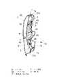
図1は本発明を採用した自動車用ドアの分解斜視図、図2は樹脂製パネル部材を車室内方から見た図、図3は樹脂製パネル部材を車室外方から見た図である。なお、本実施例ではフロントドアで説明するが、その他リアドアやバックドアなどでも同様の構造を採用してもよい。
【0022】
本実施例の自動車用ドアは、図1に示すようにインナパネルD1とアウタパネルD2とウィンドサッシュD3とで構成される鉄板製のドアパネルDと、樹脂製パネル部材Pと、車室側面をなすトリム部材Tと、ウィンドガラスWとによって構成される。本実施例の自動車用ドアはフロントドアであるため、ウィンドサッシュD3は前部が前方に傾斜するように形成されている。なお、ドアパネルD前端にはドアヒンジアッパ1とドアヒンジロア2が取付けられている。
【0023】
ドアパネルDは、前述のようにアウタパネルD1とインナパネルD2、そしてウィンドサッシュD3から構成され、このうちインナパネルD1には前方上部のコーナを三角形状に一部D1a残して、ほぼ全面に渡って開口部3が形成されている。なお、開口部3を形成しても、ベルトライン位置の上部インナパネルD1bを残していることで、インナパネルとしての剛性は、最低限確保されている。
【0024】
また、この開口部3の周縁には、複数のパネル部材取付穴4とトリム部材取付穴5が、樹脂製パネル部材Pとトリム部材Tをファスナークリップや螺合部材(図示せず)で装着できるように穿設されている。
【0025】
また、ドアパネルD内には、車体前後方向に向けてインパクトパー6が貫通配置され、ドアパネルDの側突剛性が高められている。そして、アウタパネルD2の後端上部には、アウタハンドル7が車外からドアを開閉操作するために設けられている。
【0026】
前記樹脂製パネル部材Pは、インナパネルの開口部3の形状と略一致するように、略長方形で前端上部のコーナを斜めに切り欠いた形状に成形されている。
【0027】
この樹脂製パネル部材Pの周縁には、複数の係止穴11が前記樹脂製パネル部材取付穴4に対応するように成形され、パネル部材中央部には、ウィンドガラスWをレギュレータ装置Rに組付けるためのウィンドガラス組付作業穴12が成形され、また後端上部には、アウタハンドル7とワイヤケーブル等の連結作業を行なうためのアウタハンドル連結作業穴13が成形されている。
【0028】
樹脂製パネル部材Pの車室面には、図2に示すようにパネル部材下部に、スピーカ取付部14、ポケット裏面部15、側突用パット部16が突出成形され、パネル部材中央部には、トリム部材Tを固定するためのリセスブラケット部17が突出成形されている。
【0029】
一方、樹脂製パネル部材Pの車外面には、図3に示すようにパネル部材前部に、ウィンドガラスW前端を上下方向に案内するグラスガイド18が突出成形され、また、パネル部材周縁には、防水機能を果たすラバー部材19が全周に渡って嵌装されている。
【0030】
さらに、パネル部材前端上部のコーナには、破断部20,21を介して、アウタハンドル連結作業穴13を塞ぐアウタハンドル蓋部材22と、ウィンドガラス組付作業穴12を塞ぐウィンドガラス蓋部材23が成形されている。
【0031】
アウタハンドル蓋部材22には格子状の衝撃吸収リブ22aが立設成形されており、アウタハンドル連結作業穴13を塞いだ状態で、衝撃吸収材として機能するように構成されている。
【0032】
こうした樹脂製パネル部材Pには、図に示すようにドアパネルDに組付ける前に予め複数のドア機能部品が組付けられている。
【0033】
まず、樹脂製パネル部材Pの車室面には、図2に示すように上部にインナハンドル30と車両前後方向に伸びるハンドルケーブル31が組付けられ、また、中央部にレギュレータ装置RのモータR1が組付けられ、スピーカ取付部14にはフロントスピーカを構成するスピーカ装置32が取付けられている。
【0034】
一方、パネル部材の車外面には、図3に示すように中央部にレギュレータ装置RのガイドレールR2、ドラムプーリR3、ケーブルR4等が組付けられ、また、後端部に車体ストライカ(図示せず)に係脱するドアラッチ本体33が組付けられている。
【0035】
さらに、樹脂製パネル部材Pの全域には、各ドア機能部品に電気を送電するハーネスHが張り巡らされている。このハーネスは、途中、中央部に設けられた挿通穴34を挿通して、前半部分(図3の実線部分)が樹脂製パネル部材Pの車外面に、後半部分(図2の実線部分)が樹脂製パネル部材の車室面に位置するように張り巡らされている。
【0036】
前記トリム部材Tは、図1に示すように樹脂製パネル部材Pを組み付けた後にドアパネルDに組付けられ、車室側面を構成する。
【0037】
トリム部材Tの中央部には、パワーウィンド装置やドアロック装置のスイッチ類40が設けられ、その後方にアシストグリップ41、アームレスト42が設けられている。トリム部材Tの下部には、スピーカカバー43、ポケット部44が、それぞれ樹脂製パネル部材Pのスピーカ取付部14、ポケット裏面部15に対応して設けられている。
【0038】
前記ウィンドガラスWもドアパネルDに樹脂製パネル部材Pを組付けた後に、ウィンドサッシュD3側からドアパネルD内に差込まれて、樹脂製パネル部材Pのレギュレータ装置Rに組付けられる。
【0039】
次に、図4〜図19により、自動車用ドアの各部位の詳細構造を説明する。
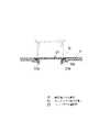
図4は、ドアパネルDに各部材を組付けて自動車用ドアを完成した状態の中央縦断面図である。
【0040】
インナパネルD1b,D1cとアウタパネルD2によって構成されたドアパネルDの内部には、樹脂製パネル部材Pに組付けられたレギュレータ装置のガイドレールR2が上下方向に配設され、その車外側にガイドレールR2によって案内されるウィンドガラスWが配置され、さらにその車外側には、インパクトバー6が配置されている。
【0041】
樹脂製パネル部材Pは、車室内の防水性を確保するため、上部インナパネルD1bと下部インナパネルD1cにラバー部材19を当接させて、開口部3を閉塞にするようにインナパネルD1b,D1cに装着されている。
【0042】
樹脂製パネル部材Pに組付けられるガイドレールR2は、パネル部材の車外面に成形された固定リブ45と、固定ボス部46、係止ボス部47で背面が支持され、上端の固定ボルト50と下端の切起こし部51によって樹脂製パネル部材Pに組付けられている。
【0043】
トリム部材Tは、トリム部材上端Taを上部インナパネルD1bとウィンドガラスWとの間に差込み、トリム部材下端Tbを下部インナパネルD1cの下端部に組付けることにより、樹脂製パネル部材Pを覆うようドアパネルDに組付けられている。
【0044】
トリム部材Tの下部には、ポケット部44が車室側に膨出するように形成され、このポケット部44の車外側には、樹脂製パネル部材のポケット裏面部15が対応して設定され、両者で小物を収納する収納ポケット53が構成されている。
【0045】
図5により、ガイドレールR2の樹脂製パネル部材Pへの組付方法を説明する。
【0046】
まず、ガイドレール下端の切起こし部51を係止ボス部47に差込み、ガイドレールR2を樹脂製パネル部材Pに仮預けして、次にガイドレールR2に穿設された貫通穴R2aに固定ボス部46の係止ピン46aを係合させ、最後に固定ボルト50を、ガイドレール上端の貫通穴R2bを挿通させて固定ボス部46に螺合固定する。
【0047】
このようにガイドレールR2を樹脂製パネル部材Pに仮預けして組付けることにより、ガイドレールR2の組付け作業を容易に行なうことができる。
【0048】
図6は、自動車用ドアを完成した状態での後部下端の縦断面図である。この図に示すように、樹脂製パネル部材Pの側突用パット部16は、ウィンドガラスW位置からトリム部材T近傍位置まで、車外側から車室側に突出成形され、内部には格子状の衝撃吸収リブ60が車外側を開放するように成形されている。この側突用パッド部16は、車両側突時にアウタパネルD2に貼着された側突用パット61から側突による押圧力を受けて、車室内乗員の腰部(図示せず)に側突変位を即座に伝達できるように構成されている。
【0049】
図7は、インナハンドル30の樹脂製パネル部材Pへの組付け状態を示す斜視図である。この図に示すようにインナハンドル30は、直接樹脂製パネル部材Pに成形されたベース部62に組付けられ、別途ベース部材などを設けなくても、インナハンドル30を構成することができる。
【0050】
インナハンドル30はロックノブ30aとレリーズノブ30bによって構成され、ベース部62に成形された上部リブ63と下部リブ64との間に介装され、それぞれ回動自在に構成される。
【0051】
このロックノブ30aとレリーズノブ30bには回動レバー65,66が共に一体成形されており、この回動レバーにはハンドルケーブル31のケーブルロッド(図7には図示せず)を係止する係止穴65a,66aが形成されている。また、ベース部の上部リブ63と下部リブ64の中間位置には中間リブ67が成形されている。
【0052】
図8は、インナハンドル30をベース部62に組付けた状態でのハンドルケーブル31との連係状態を示す断面図である。
【0053】
ハンドルケーブル31は、ケーブルロッド31a,31bと外筒31A,31Bによって構成され、このうちのケーブルロッド31a,31bがインナハンドル30と連係される。このインナハンドル30とケーブルロッド31a,31bの連係は、ロックノブとレリーズノブの回動レバー65,66に形成した係止穴65a,66aにケーブルロッド31a,31b先端の折曲部31c,31dを差込み、上部リブ63と下部リブ64との間にロックノブとレリーズノブの回動レバー65,66を介装することで、上部リブ63と中間リブ67が抜け止めストッパーとして機能することで構成される。
【0054】
このように、インナハンドル30とケーブルロッド31が連係されることで、別途インナハンドル30とケーブルロッド31との固定作業を行なうことなく、確実に、ロックノブ30aやレリーズノブ30bの回動操作がケーブルロッド31aを介してドアラッチ本体(図8には図示せず)に伝達される。
【0055】
なお、ハンドルケーブルの外筒31A,31Bは樹脂製パネル部材Pに成形されたケーブル固定ブラケット部67によって固定される。
【0056】
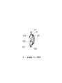
図9は、ドアラッチ本体を覆うように設けられる樹脂製のプロテクタ部材70の斜視図である。このプロテクタ部材70は、樹脂製パネルPの車外面に2つの固定部71,72を介して固定され、ドアラッチ本体の形状にほぼ対応した形状に成形されている。
【0057】
また、プロテクタ部材70には、アウタハンドルから伸びるハンドルロッド80やキーシリンダから伸びるシリンダロッド81を覆う膨出部73と、ロックノブから伸びるケーブルロッド31aやレリーズハンドルから伸びるケーブルロッド31bを覆うカバー部74,75がそれぞれ形成されている。
【0058】
なお、プロテクタ部材70の下側に膨出形成されているのは、パワードアロック装置のモータ(図示せず)を覆うモータ膨出部76である。
【0059】
なお、本実施例では、プロテクタ部材を樹脂製パネル部材Pと別体に構成したものを説明したが、一体に構成したものを採用してもよい。
【0060】
図10は、このプロテクタ部材70も含めたドアラッチ本体33周辺の横断面図である。ドアラッチ本体33は、樹脂製パネル部材P後端の車外面に固定部材82を介して固定されている。
【0061】
ドアラッチ本体33の車外位置には、前記のプロテクタ部材70がドアラッチ本体33を覆うように配置され、ウィンドガラスW側からの盗難アタックに対してドアラッチ本体33を操作されないように保護している。
【0062】
また、インナハンドル(図10には図示せず)から樹脂製パネル部材Pに沿って伸びるハンドルケーブル31は、樹脂製パネル部材P後端のプロテクタ部材70に覆われた位置に成形された挿通穴83で、パネル部材の車室面から車外面に貫通配置され、ドアラッチ本体33に連係されている。
【0063】
このようにハンドルケーブル31のほとんどを樹脂製パネル部材Pの車室側に配置していることにより、盗難アタックに対してハンドルケーブル31を操作されないように保護している。また、ハンドルケーブル31のドアラッチ本体33との連係位置も、カバー部74によって覆われているため、ウィンドガラスW側からの盗難アタックに対してハンドルケーブル31を操作されないように保護している。
【0064】
なお、インナパネルD1後端の固定ボルト84を介して組付けられるドアラッチ本体33の組付け位置には、ドアラッチ本体の取付剛性を確保するためL字状の補強プレート90が溶接されている。
【0065】
補強プレート90の斜視図を図11に示す。補強プレート90はL字状に成形された鉄板部材で構成され、中央にはドアロック時に車体ストライカを挿通するストライカ開口91が穿設され、その周囲4箇所には、ドアラッチ本体33をインナパネルD1に固定する固定ボルトを挿通するボルト穴92が穿設されている。また、補強プレート90の下端には、ドアラッチ本体側に折り曲げ成形された仮預け部93が形成されている。
【0066】
補強プレート90に仮預け部93を形成したことにより、樹脂製パネル部材PをドアパネルDに組付ける際に、重量物であるドアラッチ本体33を予め仮預け部93に仮預けすることができるため、樹脂製パネル部材Pの組付け作業を容易にすることができ、組付け工数を大幅に削減できる。
【0067】
図12は、樹脂製パネル部材Pに成形したグラスガイド18の断面図である。この図に示すように、本実施例では、従来、ドアパネルのインナパネルと別部材で構成していたグラスガイドを、樹脂製パネル部材Pに一体に構成したことにより、単にグラスガイドの溝部18aにパッド18Pを嵌装するだけでグラスガイドを容易に構成することができる。
【0068】
図13は、樹脂製パネル部材Pのスピーカ取付部14にスピーカ装置32を組付けた状態の断面図である。スピーカ装置32は車室側に隆起したスピーカ取付部14に補強リング100と取付ボルト(図示せず)によって強固に組付けられる。このスピーカ装置32の後端(車外側)には、ハーネスから伸びる結線コード101がカプラ結線102され、音響信号を受信するように構成されている。
【0069】
スピーカ装置32の上方の樹脂製パネル部材Pには、このスピーカ装置の後端(車外側)を覆うようにヒサシ部103が突出成形されている。このヒサシ部103によって、スピーカ装置32の電気系統に雨水等が飛散しないように設定されている。
【0070】
図14,図15は、樹脂製パネル部材Pの各部位に成形されたハーネスHやケーブルワイヤ31を係止する係止部の詳細を示す斜視図である。
【0071】
図14に示すように、ハーネスHを係止するハーネス係止部110は、樹脂製パネル部材Pの表面に一対に互い違いに突出成形されたL字状の係止片110a,110bによって構成されている。この一対の係止片110a,110bに対してハーネスHを係止するには、図示するように一対の係止片110a,110bの間にハーネスHを位置させた上で、それぞれ矢印の方向にハーネスHを回転させることで係止することができる。
【0072】
図15に示すように、ケーブルワイヤ31を係止するケーブル係止部111は、樹脂製パネル部材Pの表面に突出成形されたJ字状のフック片111aで構成されている。このフック片111aにケーブルワイヤ31を係止するには、図示するように上方から矢印の方向にケーブルワイヤ31を差込むことで係止することができる。
【0073】
このようにハーネスやケーブルワイヤを係止する係止部110,111を、樹脂製パネル部材Pに一体成形していることにより、従来、別途設定していたクリップ類を廃止することができ、これらワイヤ類の組付け作業を簡略化することができる。
【0074】
図16と図17は、アウタハンドル蓋部材22、ウィンドガラス蓋部材23を樹脂製パネル部材Pから破断分離する前の断面図である。
【0075】
アウタハンドル蓋部材22は図16に示すように樹脂製パネル部材Pと破断部20を介して一体成形されており、車外面、車室面に共に格子状の衝撃吸収リブ部22aを設けて形成されている。また、アウタハンドル蓋部材22の車外面端部には係止爪部22bが立設形成され、その外側には防水性を確保するラバー部材22cが嵌装されている。
【0076】
ウィンドガラス蓋部材23も図17に示すように、樹脂製パネル部材Pと破断部21を介して一体成形されており、車外面の端部には係止爪部23bが立設形成され、その外側にラバー部材23cが嵌装されている。
【0077】
図18と図19は、アウタハンドル蓋部材22、ウィンドガラス蓋部材23を破断部21,22で破断分離した後、それぞれの作業穴に装着した状態の断面図である。
【0078】
アウタハンドル蓋部材22は、図18に示すように樹脂製パネル部材Pのアウタハンドル連結作業穴13に車室側から矢印方向に嵌め込むことにより、作業穴周縁の係合段部13aに係止爪部22bが係止され、アウタハンドル連結作業穴13を閉塞することができる。
【0079】
また、ウィンドガラス蓋部材23も、図19に示すように樹脂製パネル部材Pのウィンドガラス組付作業穴12に車室側から矢印方向に嵌め込むことにより、作業穴周縁の係合段部12aに係止爪部23bが係止され、ウィンドガラス組付作業穴12を閉塞することができる。
【0080】
このように、各蓋部材22,23によってアウタハンドル連結作業穴13とウィンドガラス組付作業穴12を閉塞することにより、ドア組立作業において必要な作業穴12,13を樹脂製パネル部材Pに形成しつつ、作業後は確実にこれら作業穴12,13を閉塞することができるため車室内の防水性を確保することができる。
【0081】
次に、本実施例の自動車用ドアの組立方法について説明する。
まず、アウタハンドル蓋部材22、ウィンドガラス蓋部材23と樹脂製パネル部材Pとが破断部20,21を介して一体となったパネル体を、大型の成形型に大量の樹脂材料を一度に噴射することで、インジェクション成形する。
【0082】
次に、このパネル体をドア組立作業位置まで搬送する。このとき、パネル体は略長方形の平板状に成形されているため、搬送や積み重ねが容易にかつ確実に行なえる。
【0083】
次に、アウタハンドル蓋部材22、ウィンドガラス蓋部材23を破断分離することなく、樹脂製パネル部材Pにレギュレータ装置RやハーネスH等の複数のドア機能部品を組付ける。これらの組付けについては、前記したように極めて容易に行なうことができる。
【0084】
次に、この複数のドア機能部品を組付けた樹脂製パネル部材Pを、そのままドアパネルDに組付ける。この時、まず樹脂製パネル部材Pをインナパネルの開口部3に装着して、ドアラッチ本体33をインナパネルD1に固定する。そして、ウィンドガラスWをドアパネルD内に差込んで、ウィンドガラスWとレギュレータ装置Rの組付作業を行ない、アウタハンドル7とワイヤケーブル等の連結作業を行なう。
【0085】
次に、アウタハンドル蓋部材22、ウィンドガラス蓋部材23を樹脂製パネル部材Pから破断分離して、組付、連結作業が行なわれたアウタハンドル連結作業穴13とウィンドガラス組付作業穴12に、それぞれ装着して各作業穴を閉塞する。
【0086】
最後に、樹脂製パネル部材Pを覆うようにトリム部材TをドアパネルDに装着する。
【0087】
こうした組立方法によって、自動車用ドアを完成する。
【0088】
以上のような構成及び組立方法によって、本実施例の自動車用ドアは次のような効果を奏する。
【0089】
まず、アウタハンドル蓋部材22とウィンドガラス蓋部材23を樹脂製パネル部材Pと破断部20,21を介して一体成形したことにより、一度にこれらの樹脂製品を成形することができるため、大型、大量の設備等を有効に使用することができ、樹脂製パネル部材成形時の生産効率を高めることができる。
【0090】
なお、本実施例では、蓋部材を一体成形したが、この他プロテクタ部材などを一体成形してもよい。
【0091】
また、これら蓋部材22,23を一体成形した部位が、樹脂製パネル部材Pの切り欠いたコーナ位置であるため、一体成形した状態のパネル体を略長方形の平板状にすることができる。よって、成形型も効率よく設定でき、また、蓋部材を破断分離せずに、組立作業時までの搬送、積み重ね作業を容易に行なえる。
【0092】
また、これら蓋部材22,23を破断分離する作業を、ドア組立作業時、特にウィンドガラスW、アウタハンドル7の組付連結作業後に行なうことにより、これら蓋部材22,23を紛失する恐れもなくなり、確実に作業穴12,13を閉塞することができる。
【0093】
以上、好適な実施例について説明したが、本発明はこれら実施例に限定されるものではなく、インナパネルの開口に装着される樹脂製パネル部材に他の樹脂製部材を破断部を介して一体成形するものであれば全て包括するものであり、その他、本発明の趣旨を逸脱しない限りにおいて、適宜詳細構造を変更してもよい。
【図面の簡単な説明】
【図1】本発明を採用した自動車用ドアの分解斜視図。
【図2】樹脂製パネル部材を車室内方から見た図。
【図3】樹脂製パネル部材を車室外方から見た図。
【図4】自動車用ドアを完成した状態の中央縦断面図。
【図5】ガイドレールの組付方法を示す斜視図。
【図6】自動車ドアを完成した状態の後部下端の縦断面図。
【図7】インナハンドルの組付状態を示す斜視図。
【図8】インナハンドルとハンドルケーブルの連係状態を示す断面図。
【図9】プロテクタ部材の斜視図。
【図10】ドアラッチ本体周辺の横断面図。
【図11】補強プレートの斜視図。
【図12】グラスガイドの断面図。
【図13】スピーカ取付部の断面図。
【図14】ハーネス係止部の斜視図。
【図15】ケーブル係止部の斜視図。
【図16】アウタハンドル蓋部材の破断分離前の断面図。
【図17】ウィンドガラス蓋部材の破断分離前の断面図。
【図18】アウタハンドル蓋部材の作業穴装着時の断面図。
【図19】ウィンドガラス蓋部材の作業穴装着時の断面図。
【符号の説明】
D…ドアパネル
D1…インナパネル
D2…アウタパネル
P…樹脂製パネル部材
T…トリム部材
R…レギュレータ装置
H…ハーネス
3…開口部
12…ウィンドガラス組付作業穴
13…アウタハンドル連結作業穴
20…破断部
21…破断部
22…アウタハンドル蓋部材
23…ウィンドガラス蓋部材[0001]
BACKGROUND OF THE INVENTION
The present invention separately sets a resin panel member that closes an opening formed in an inner panel in order to reduce the weight of an automobile door, improve assembly, and reduce the number of parts. The present invention relates to an automobile door constituting a door by assembling door functional parts such as a regulator device and an automobile door assembly method.
[0002]
[Prior art]
Conventionally, automobile doors have been configured by assembling door functional parts such as a regulator device and a door lock device directly on an iron plate door panel including an inner panel and an outer panel.
[0003]
However, in recent years, as described in JP-A-9-156374, an opening formed in the inner panel, as described in JP-A-9-156374, in order to improve the assemblability, reduce the number of parts, and reduce the weight of the door. It is conceived that a resin panel member to be mounted on the inner panel is set so as to close the door, and a door functional component is assembled in advance to the panel member to constitute an automobile door.
[0004]
When the resin panel member is set separately as described above, the inner panel side shape can be freely changed to a complicated shape. Since the stop member can be eliminated and the door functional parts can be arranged at various places, a great effect that the degree of freedom of layout inside the door can be increased can be obtained.
[0005]
[Problem to be Solved by the Invention]
By the way, when molding such a resin panel member, molding is performed using press molding or injection (injection) molding.
[0006]
As described in the above publication, when the almost entire surface on the inner panel side is constituted by a single panel member, it is necessary to make it a considerably large panel member.
[0007]
For this reason, when setting a resin panel member to be mounted on the door panel, a considerably large mold is required, a large amount of resin material is required, and the molding pressure and injection pressure need to be set to a very high level. there were.
[0008]
However, it is not necessarily good to use these large-scale and large-scale facilities to form only one resin panel member in view of production efficiency.
[0009]
The present invention has been invented in view of the above-described problems, and is an automobile that can increase the production efficiency when molding a resin panel member, in which a resin panel member to be mounted on an automobile door is set. The main object is to provide a method for assembling an automobile door and an automobile door.
[0010]
[Means for Solving the Problems]
In order to solve the above problems, the present invention is configured as follows.
[0011]
According to a first aspect of the present invention, there is provided an automotive door in which a door functional component is assembled to a resin panel member mounted on an inner panel so as to close an opening formed in the inner panel. The panel member is provided with a breaking part that breaks during assembly work,Assembly member to be assembled to a predetermined part of the resin panel memberAre integrally molded.
[0012]
The invention according to claim 2In an automobile door that constitutes a door by assembling a door functional component to a resin panel member mounted on the inner panel so as to close an opening formed in the inner panel, the resin panel member is attached to the resin panel member during assembly work. A lid member that is provided with a rupture portion that breaks and closes a work hole for assembly work formed in the resin panel member is integrally formed..
[0013]
The invention described in
[0014]
The invention according to claim 4In the method of assembling the door by assembling the door functional parts to the resin panel member mounted on the inner panel so as to close the opening formed in the inner panel, the resin panel member is integrally formed at the time of door assembly work. A method for assembling an automobile door in which a predetermined resin part is broken at a breaking portion and the predetermined resin part is assembled to a predetermined part of a resin panel member after the breakage.
[0015]
[Action and effect]
According to the first aspect of the present invention, the resin panel member is provided with the breaking portion that is broken during the assembly operation, and the predetermined resin part is integrally formed, so that the predetermined resin part is also formed of the resin panel. Since the members can be simultaneously formed when forming the member, large-scale and large-scale facilities can be used effectively at a time, and the production efficiency at the time of forming the resin panel member can be increased.
In particular,By using a predetermined resin part as an assembly member that can be assembled to a predetermined part of the resin panel member, for example, the flat panel body remains as it is without breaking and separating the resin panel member and the assembly member. It can be conveyed to the door assembly position, and the assembly member can be broken and separated from the resin panel member at the time of door assembly work, and can be assembled to a predetermined part of the resin panel member. For this reason, the fear that the assembly member is lost before the assembly can be eliminated.
[0016]
According to the automobile door according to
[0017]
According to the automobile door according to
[0018]
For example, when the resin panel member is formed as a shape in which a rectangular corner portion is cut out corresponding to the shape of the opening of the inner panel, the corner portionAssembling member or lid memberBy forming, a substantially rectangular flat panel body can be obtained, and conveyance and stacking become extremely easy.
[0019]
Claim4According to the described method for assembling an automobile door, at the time of door assembly work, a predetermined resin part integrally molded with a resin panel member is broken and separated at a breaking portion, and after breaking and separating, the predetermined resin part is resinated. By adopting a method of assembling to a predetermined part of the panel member, the resin panel member and the predetermined resin part can be integrated until the door assembly operation. Therefore, the predetermined resin parts can be reliably assembled to the resin panel member during the door assembly operation without losing the predetermined resin parts.
[0020]
【Example】
Embodiments of the present invention will be described below in detail with reference to the drawings.
[0021]
FIG. 1 is an exploded perspective view of an automobile door employing the present invention, FIG. 2 is a view of a resin panel member as viewed from the inside of the vehicle interior, and FIG. 3 is a view of the resin panel member as viewed from the outside of the vehicle interior. In this embodiment, the front door will be described, but the same structure may be adopted for other rear doors and back doors.
[0022]
As shown in FIG. 1, the automobile door of the present embodiment includes an iron panel door panel D composed of an inner panel D1, an outer panel D2, and a wind sash D3, a resin panel member P, and a trim that forms the side surface of the passenger compartment. It is comprised by the member T and the window glass W. Since the automobile door of the present embodiment is a front door, the wind sash D3 is formed so that the front portion is inclined forward. A door hinge upper 1 and a door hinge lower 2 are attached to the front end of the door panel D.
[0023]
As described above, the door panel D is composed of the outer panel D1, the inner panel D2, and the wind sash D3. Of these, the inner panel D1 is open over almost the entire surface, leaving a part of the upper corner in the triangle shape D1a.
[0024]
In addition, a plurality of panel
[0025]
Further, in the door panel D, an
[0026]
The resin panel member P is formed in a substantially rectangular shape with a corner at the upper front end cut obliquely so as to substantially match the shape of the
[0027]
A plurality of locking
[0028]
As shown in FIG. 2, a
[0029]
On the other hand, on the outer surface of the resin panel member P, as shown in FIG. 3, a
[0030]
Further, an outer
[0031]
The outer
[0032]
A plurality of door functional parts are assembled in advance on such a resin panel member P before assembling to the door panel D as shown in the figure.
[0033]
First, as shown in FIG. 2, an
[0034]
On the other hand, as shown in FIG. 3, a guide rail R2, a drum pulley R3, a cable R4, and the like of the regulator device R are assembled at the center portion on the vehicle outer surface of the panel member, and a vehicle body striker (not shown) is disposed at the rear end portion. The door latch
[0035]
Furthermore, a harness H that transmits electricity to each door functional component is stretched over the entire area of the resin panel member P. In the middle of this harness, an
[0036]
The trim member T is assembled to the door panel D after assembling the resin panel member P as shown in FIG.
[0037]
A
[0038]
The window glass W is also inserted into the door panel D from the wind sash D3 side after the resin panel member P is assembled to the door panel D, and is assembled to the regulator device R of the resin panel member P.
[0039]
Next, a detailed structure of each part of the automobile door will be described with reference to FIGS.
FIG. 4 is a central longitudinal cross-sectional view of a state in which each member is assembled to the door panel D to complete the automobile door.
[0040]
Inside the door panel D constituted by the inner panels D1b, D1c and the outer panel D2, a guide rail R2 of the regulator device assembled to the resin panel member P is arranged in the vertical direction, and the guide rail R2 is disposed outside the vehicle. Is disposed, and an
[0041]
The resin panel member P has inner panels D1b and D1c so as to close the
[0042]
The guide rail R2 assembled to the resin panel member P is supported on the back by a fixing
[0043]
The trim member T covers the resin panel member P by inserting the trim member upper end Ta between the upper inner panel D1b and the window glass W and assembling the trim member lower end Tb to the lower end portion of the lower inner panel D1c. It is assembled to the door panel D.
[0044]
At the lower part of the trim member T, a
[0045]
A method for assembling the guide rail R2 to the resin panel member P will be described with reference to FIG.
[0046]
First, the cut-and-raised
[0047]
Thus, the guide rail R2 can be easily assembled by temporarily depositing it on the resin panel member P and assembling it.
[0048]
FIG. 6 is a longitudinal sectional view of the lower end of the rear part in a state in which the automobile door is completed. As shown in this figure, the
[0049]
FIG. 7 is a perspective view showing an assembled state of the
[0050]
The
[0051]
The
[0052]
FIG. 8 is a cross-sectional view illustrating a state in which the
[0053]
The
[0054]
As described above, the
[0055]
The
[0056]
FIG. 9 is a perspective view of a
[0057]
Further, the
[0058]
A bulge formed on the lower side of the
[0059]
In the present embodiment, the protector member is configured separately from the resin panel member P. However, an integrally configured protector member may be employed.
[0060]
FIG. 10 is a cross-sectional view of the periphery of the
[0061]
The
[0062]
Further, the
[0063]
As described above, most of the
[0064]
Note that an L-shaped reinforcing
[0065]
A perspective view of the reinforcing
[0066]
Since the
[0067]
FIG. 12 is a cross-sectional view of the
[0068]
FIG. 13 is a cross-sectional view of a state in which the
[0069]
On the resin panel member P above the
[0070]
14 and 15 are perspective views showing details of a locking portion that locks the harness H and the
[0071]
As shown in FIG. 14, the
[0072]
As shown in FIG. 15, the
[0073]
In this way, by integrally forming the locking
[0074]
16 and 17 are sectional views before the outer
[0075]
As shown in FIG. 16, the outer
[0076]
As shown in FIG. 17, the window
[0077]
18 and 19 are cross-sectional views showing a state in which the outer
[0078]
As shown in FIG. 18, the outer
[0079]
Further, as shown in FIG. 19, the window
[0080]
In this manner, the outer handle connecting
[0081]
Next, a method for assembling the automobile door of this embodiment will be described.
First, a panel body in which the outer
[0082]
Next, this panel body is conveyed to a door assembly work position. At this time, since the panel body is formed in a substantially rectangular flat plate shape, it can be transported and stacked easily and reliably.
[0083]
Next, a plurality of door functional parts such as the regulator device R and the harness H are assembled to the resin panel member P without breaking and separating the outer
[0084]
Next, the resin panel member P assembled with the plurality of door functional parts is assembled to the door panel D as it is. At this time, first, the resin panel member P is attached to the
[0085]
Next, the outer
[0086]
Finally, the trim member T is mounted on the door panel D so as to cover the resin panel member P.
[0087]
The automobile door is completed by such an assembly method.
[0088]
With the above-described configuration and assembling method, the automobile door of this embodiment has the following effects.
[0089]
First, since the outer
[0090]
In the present embodiment, the lid member is integrally formed, but other protector members and the like may be integrally formed.
[0091]
Moreover, since the site | part which integrally molded these
[0092]
Further, the work of breaking and separating the
[0093]
Although the preferred embodiments have been described above, the present invention is not limited to these embodiments, and another resin member is integrated with the resin panel member attached to the opening of the inner panel via the breaking portion. If it shape | molds, all are included, and unless it deviates from the meaning of this invention, you may change a detailed structure suitably.
[Brief description of the drawings]
FIG. 1 is an exploded perspective view of an automobile door adopting the present invention.
FIG. 2 is a view of a resin panel member as viewed from the inside of the vehicle interior.
FIG. 3 is a view of a resin panel member as viewed from the outside of the passenger compartment.
FIG. 4 is a central longitudinal sectional view showing a state in which a door for an automobile is completed.
FIG. 5 is a perspective view showing a method of assembling the guide rail.
FIG. 6 is a longitudinal sectional view of the lower end of the rear part in a state where the automobile door is completed.
FIG. 7 is a perspective view showing an assembled state of the inner handle.
FIG. 8 is a cross-sectional view showing a state where the inner handle and the handle cable are linked.
FIG. 9 is a perspective view of a protector member.
FIG. 10 is a cross-sectional view around the door latch body.
FIG. 11 is a perspective view of a reinforcing plate.
FIG. 12 is a cross-sectional view of a glass guide.
FIG. 13 is a cross-sectional view of a speaker mounting portion.
FIG. 14 is a perspective view of a harness locking portion.
FIG. 15 is a perspective view of a cable locking portion.
FIG. 16 is a cross-sectional view of the outer handle lid member before breaking and separation.
FIG. 17 is a cross-sectional view of the wind glass lid member before breaking separation.
FIG. 18 is a cross-sectional view of the outer handle lid member when the working hole is mounted.
FIG. 19 is a cross-sectional view of the window glass lid member when the work hole is mounted.
[Explanation of symbols]
D ... Door panel
D1 ... Inner panel
D2 ... Outer panel
P: Panel member made of resin
T ... Trim member
R ... Regulator device
H ... Harness
3 ... Opening
12 ... UIGlass assembly hole
13 ... Outer handle connecting hole
20 ... fracture part
21 ... Broken part
22 ... Outer handle cover member
23. Wind glass lid member
Claims (4)
Translated fromJapanese前記樹脂製パネル部材に、組立作業時に破断する破断部を設け、
前記樹脂製パネル部材の所定部位に組付けられる組付け部材を一体成形した、
自動車用ドア。In what constitutes a door by assembling a door functional component to a resin panel member mounted on the inner panel so as to close the opening formed in the inner panel,
The resin panel member is provided with a breaking portion that breaks during assembly work,
An assembly member tobe assembled to a predetermined part of the resin panel member is integrally molded,
Automotive door.
前記樹脂製パネル部材に、組立作業時に破断する破断部を設け、
前記樹脂製パネル部材に形成した組立作業用の作業穴を塞ぐ蓋部材を一体成形した、
自動車用ドア。In what constitutes a door by assembling a door functional component to a resin panel member mounted on the inner panel so as to close the opening formed in the inner panel,
The resin panel member is provided with a breaking portion that breaks during assembly work,
A lid member that closes a work hole for assembly work formed in the resin panel member is integrally formed,
Automotive door.
前記組付け部材又は前記蓋部材を、前記樹脂製パネル部材の前記車室側壁の一部に対応する部位に形成した、
請求項1又は2記載の自動車用ドア。The opening is formed by leaving a part of the inner panel so as to form a side wall of the passenger compartment,
The assembly member or the lid member is formed in a portion corresponding to a part of the vehicle compartment side wall of the resin panel member.
The automobile door according to claim1 or 2 .
ドア組立作業時に、樹脂製パネル部材に一体成形した所定の樹脂製部品を破断部で破断して、At the time of door assembly work, a predetermined resin part molded integrally with the resin panel member is broken at the break portion,
破断後に、前記所定の樹脂製部品を樹脂製パネル部材の所定部位に組付ける、After breaking, the predetermined resin part is assembled to a predetermined part of the resin panel member,
自動車用ドアの組立方法。Assembly method for automobile doors.
Priority Applications (4)
| Application Number | Priority Date | Filing Date | Title |
|---|---|---|---|
| JP2000053666AJP3882448B2 (en) | 2000-02-29 | 2000-02-29 | Automobile door and method of assembling the autodoor |
| DE60105331TDE60105331T2 (en) | 2000-02-29 | 2001-02-13 | Vehicle door and method of mounting the vehicle door |
| EP01103360AEP1129873B1 (en) | 2000-02-29 | 2001-02-13 | Vehicle door and process of assembling the vehicle door |
| US09/790,313US6449907B2 (en) | 2000-02-29 | 2001-02-21 | Vehicle door and process of assembling the vehicle door |
Applications Claiming Priority (1)
| Application Number | Priority Date | Filing Date | Title |
|---|---|---|---|
| JP2000053666AJP3882448B2 (en) | 2000-02-29 | 2000-02-29 | Automobile door and method of assembling the autodoor |
Publications (2)
| Publication Number | Publication Date |
|---|---|
| JP2001239836A JP2001239836A (en) | 2001-09-04 |
| JP3882448B2true JP3882448B2 (en) | 2007-02-14 |
Family
ID=18575018
Family Applications (1)
| Application Number | Title | Priority Date | Filing Date |
|---|---|---|---|
| JP2000053666AExpired - Fee RelatedJP3882448B2 (en) | 2000-02-29 | 2000-02-29 | Automobile door and method of assembling the autodoor |
Country Status (4)
| Country | Link |
|---|---|
| US (1) | US6449907B2 (en) |
| EP (1) | EP1129873B1 (en) |
| JP (1) | JP3882448B2 (en) |
| DE (1) | DE60105331T2 (en) |
Families Citing this family (73)
| Publication number | Priority date | Publication date | Assignee | Title |
|---|---|---|---|---|
| US6931791B1 (en)* | 1999-07-22 | 2005-08-23 | Brose Fahrzeugteile Gmbh & Co. Kg, Coburg | System to be fitted in a vehicle door |
| JP3738989B2 (en)* | 1999-07-23 | 2006-01-25 | 日本板硝子株式会社 | Vehicle window glass and vehicle door structure provided with the window glass |
| US7363750B2 (en)* | 2000-07-25 | 2008-04-29 | Alcoa Inc. | Sliding vehicle door with a moveable window assembly |
| FR2812847A1 (en)* | 2000-08-08 | 2002-02-15 | Sai Automotive Allibert Ind | MOTOR VEHICLE DOOR |
| EP1370434B1 (en)* | 2001-03-22 | 2006-06-14 | Intier Automotive Inc. | Method for manufacturing a vehicular door assembly |
| JP4602614B2 (en)* | 2001-09-26 | 2010-12-22 | アイシン精機株式会社 | Automotive door |
| US6857688B2 (en) | 2001-10-31 | 2005-02-22 | Lear Corporation | Integrated door module |
| US20030097798A1 (en)* | 2001-11-27 | 2003-05-29 | Staser Brian Hale | Vehicle door module |
| CA2434441A1 (en) | 2003-01-07 | 2005-01-03 | David Legault | Trim door hardware carrier and method of assembling vehicle door |
| AU2003201418A1 (en)* | 2002-01-07 | 2003-07-24 | Intier Automotive Closures Inc. | Trim hardware carrier |
| EP1484208B1 (en)* | 2002-03-11 | 2010-04-07 | Grupo Antolin-Ingenieria, S.A. | Door module for motor vehicles comprising a window regulator with lever |
| US6550846B1 (en)* | 2002-06-05 | 2003-04-22 | Ford Global Technologies, Inc. | Aluminum automotive door assembly |
| DE10230073A1 (en)* | 2002-07-01 | 2004-01-22 | Sai Automotive Sal Gmbh | Motor vehicle door |
| AU2003270094A1 (en)* | 2002-10-31 | 2004-05-25 | Voestalpine Motion Gmbh | Vehicle door |
| US6676195B1 (en)* | 2002-11-15 | 2004-01-13 | Creative Foam Corp. | Self-sealing door water shield barrier |
| JP2004175171A (en)* | 2002-11-26 | 2004-06-24 | Mitsubishi Motors Corp | Vehicle door |
| DE10256266A1 (en)* | 2002-12-03 | 2004-06-24 | Kiekert Ag | Motor vehicle door |
| US20040122719A1 (en)* | 2002-12-18 | 2004-06-24 | Sabol John M. | Medical resource processing system and method utilizing multiple resource type data |
| FR2851205B1 (en)* | 2003-02-14 | 2006-04-14 | Arvinmeritor Light Vehicle Sys | DOOR MODULE AND DOOR ASSEMBLY METHOD |
| US7591104B2 (en)* | 2003-07-23 | 2009-09-22 | Ohi Seisakusho Co., Ltd. | Mounting structure of a power window apparatus |
| KR100520202B1 (en)* | 2003-09-02 | 2005-10-12 | 기아자동차주식회사 | Door Glass Guide of a Vehicle |
| CA2481013A1 (en)* | 2003-09-16 | 2004-04-29 | Grupo Antolin-Ingenieria, S.A. | Support module with impervious closure for vehicle doors and method of mounting said module |
| US6938944B2 (en)* | 2004-01-20 | 2005-09-06 | Foamade Industries, Inc. | Water shield with integrated 3-D mirror seal |
| US6908140B1 (en)* | 2004-02-24 | 2005-06-21 | Arvinmeritor Technology, Llc | Door module cable holder |
| US7073843B2 (en)* | 2004-04-06 | 2006-07-11 | Lear Corporation | Trim panel assembly and method of manufacture |
| CN1976824B (en)* | 2004-06-23 | 2013-08-28 | 英提尔汽车系统公司 | Structural door module |
| US7059659B2 (en)* | 2004-07-26 | 2006-06-13 | Lear Corporation | Vehicle door barrier panel having removable attachment tabs |
| DE202004011851U1 (en)* | 2004-07-28 | 2004-09-30 | Peguform Gmbh & Co. Kg | Automotive rear door |
| DE102004045453B4 (en)* | 2004-09-20 | 2010-05-12 | Lisa Dräxlmaier GmbH | Pre-assembly unit for a motor vehicle |
| BRPI0516390A (en) | 2004-10-22 | 2008-09-02 | Dow Global Technologies Inc | method for producing a shaped composite article, shaped plastic article, article and article use |
| ATE411918T1 (en)* | 2005-03-01 | 2008-11-15 | Antolin Grupo Ing Sa | STRUCTURAL MODULE CARRIER FOR VEHICLE DOORS |
| US8109559B2 (en)* | 2005-04-18 | 2012-02-07 | Mitsubishi Jidosha Kogyo Kabushiki Kaisha | Door structure of vehicle |
| US20060264554A1 (en)* | 2005-05-17 | 2006-11-23 | Arnold Lustiger | Fiber reinforced polypropylene composite door core modules |
| CN1991122A (en)* | 2005-12-14 | 2007-07-04 | 德韧环球技术有限公司 | Door hardware module |
| WO2007111787A1 (en) | 2006-03-23 | 2007-10-04 | Exxonmobil Chemical Patents Inc. | Door core module |
| US20070220812A1 (en)* | 2006-03-23 | 2007-09-27 | Jeffrey Valentage | Door core module |
| WO2007111788A1 (en) | 2006-03-23 | 2007-10-04 | Exxonmobil Chemical Patents Inc. | Hybrid door core and trim module with integrated components |
| US20070222256A1 (en)* | 2006-03-23 | 2007-09-27 | Jeffrey Valentage | Hybrid door core and trim module with integrated components |
| WO2007111785A1 (en) | 2006-03-23 | 2007-10-04 | Exxonmobil Chemical Patents Inc. | Core module for door assembly having integrated reinforcements |
| DE602007004456D1 (en) | 2006-03-23 | 2010-03-11 | Exxonmobil Chem Patents Inc | DOOR ARRANGEMENT WITH CORE MODULE WITH INTEGRATED BELT LINE REINFORCEMENT |
| WO2007111786A1 (en) | 2006-03-23 | 2007-10-04 | Exxonmobil Chemical Patents Inc. | Door assembly with integrated window sealing system |
| US20070267889A1 (en)* | 2006-03-23 | 2007-11-22 | Flendrig Joseph G M | Door assembly with core module having integrated belt line reinforcement |
| US20080098655A1 (en)* | 2006-10-31 | 2008-05-01 | Jeffrey Valentage | Integrated bracket for mounting pulley |
| US20070222249A1 (en)* | 2006-03-23 | 2007-09-27 | Jeffrey Valentage | Interior trim panel with integrated living hinged components |
| US20070222257A1 (en)* | 2006-03-23 | 2007-09-27 | Joseph Gustaaf Marie Flendrig | Core module for door assembly having integrated reinforcements |
| US20070220811A1 (en)* | 2006-03-23 | 2007-09-27 | Joseph Gustaaf Marie Flendrig | Door assembly with integrated window sealing system |
| US7338314B2 (en)* | 2006-07-27 | 2008-03-04 | Ford Global Technologies, Llc | Electrical wire routing connector presenter bracket |
| JP5148870B2 (en)* | 2006-12-15 | 2013-02-20 | 三井金属アクト株式会社 | Car door structure |
| JP4466676B2 (en) | 2007-04-06 | 2010-05-26 | 日産自動車株式会社 | Shock absorber mounting structure |
| US20090051193A1 (en)* | 2007-08-22 | 2009-02-26 | Hernandez Everardo A | Window regulator system for a vehicle door assembly |
| WO2009029412A1 (en)* | 2007-08-31 | 2009-03-05 | Exxonmobil Chemical Patents Inc. | Door module with integrated cable bundle |
| KR100878118B1 (en)* | 2007-11-08 | 2009-01-14 | 지엠대우오토앤테크놀로지주식회사 | Door glass switchgear of car |
| US20100026018A1 (en)* | 2008-07-31 | 2010-02-04 | International Automotive Components Group North America, Inc. | Lock knob for lock rod in motor vehicle |
| JP2011021673A (en) | 2009-07-15 | 2011-02-03 | Nifco Inc | Shock absorbing member and shock absorbing structure |
| DE202010007547U1 (en)* | 2010-05-31 | 2011-10-05 | Brose Fahrzeugteile Gmbh & Co. Kg, Hallstadt | Vehicle door with a multifunction carrier |
| DE102010031013A1 (en)* | 2010-07-06 | 2012-01-12 | Brose Fahrzeugteile Gmbh & Co. Kommanditgesellschaft, Hallstadt | Automotive windows |
| FR2964347B1 (en)* | 2010-09-02 | 2012-09-28 | Faurecia Interieur Ind | AUTOMOTIVE VEHICLE DOOR MODULE COMPRISING A WINDOW LIFTING SYSTEM |
| DE102010050959A1 (en)* | 2010-11-10 | 2012-05-10 | Gm Global Technology Operations Llc (N.D.Ges.D. Staates Delaware) | Mounting arrangement for mounting a trim panel |
| DE202012103532U1 (en)* | 2012-09-17 | 2013-12-20 | Brose Fahrzeugteile Gmbh & Co. Kommanditgesellschaft, Hallstadt | vehicle door |
| CN103963615B (en)* | 2013-01-29 | 2018-06-01 | 麦格纳覆盖件有限公司 | Car door and the door module for dividing door load-bearing part with multi-section |
| FR3001920B1 (en) | 2013-02-13 | 2016-07-15 | Renault Sas | PLASTIC RIGIDIFICATION PANEL FOR OPENING WITH FIXING A WINDOW LIFTING SYSTEM |
| JP2016030467A (en)* | 2014-07-25 | 2016-03-07 | トヨタ自動車株式会社 | Vehicle door structure |
| JP6278915B2 (en)* | 2015-02-20 | 2018-02-14 | 株式会社ニフコ | Load transmission member |
| DE102015217353A1 (en)* | 2015-05-05 | 2016-11-10 | Brose Fahrzeugteile Gmbh & Co. Kommanditgesellschaft, Bamberg | Carrier device for a motor vehicle |
| US11148511B2 (en) | 2015-07-23 | 2021-10-19 | Magna International Inc. | Vehicle door assembly |
| US10406893B2 (en)* | 2016-06-29 | 2019-09-10 | GM Global Technology Operations LLC | Inner support panel for mounting a hardware module of a vehicle door assembly |
| DE102016008728B3 (en)* | 2016-07-21 | 2017-07-27 | Brose Fahrzeugteile Gmbh & Co. Kommanditgesellschaft, Bamberg | Breakaway element for a designed as wet / dry space separation module carrier a door or flap of a motor vehicle |
| US10071665B2 (en)* | 2016-10-27 | 2018-09-11 | Honda Motor Co., Ltd. | Grab handle assembly for use in a vehicle |
| US10647183B2 (en)* | 2017-06-02 | 2020-05-12 | Magna Closures Inc. | Vehicle closure panel assembly and carrier assembly therefor |
| US20180354349A1 (en)* | 2017-06-12 | 2018-12-13 | Magna Closures Inc. | Door assembly with split carrier module |
| US10967714B2 (en)* | 2017-09-25 | 2021-04-06 | Ford Global Technologies, Llc | Collapsible side door latch module |
| DE102019216278A1 (en)* | 2019-10-23 | 2021-04-29 | Brose Fahrzeugteile Se & Co. Kommanditgesellschaft, Bamberg | Unit carrier of a vehicle door |
| US20230356572A1 (en)* | 2022-05-03 | 2023-11-09 | Magna Closures Inc. | Structural module having frangible extension member |
Family Cites Families (13)
| Publication number | Priority date | Publication date | Assignee | Title |
|---|---|---|---|---|
| DE3423827A1 (en)* | 1984-06-04 | 1985-02-14 | Stübbe GmbH, 2940 Wilhemshaven | PLASTIC DOOR FOR MOTOR VEHICLES |
| US4868715A (en)* | 1988-05-31 | 1989-09-19 | Scosche Industries, Inc. | Break-away panel structure for radio in-dash installation kit |
| US5535553A (en)* | 1994-11-16 | 1996-07-16 | General Motors Corporation | Superplug vehicle door module |
| DE19511105C1 (en)* | 1995-03-25 | 1996-11-21 | Brose Fahrzeugteile | Double-skin vehicle door with a double-strand cable window lifter pre-assembled on a carrier plate |
| JP3067092B2 (en) | 1995-12-08 | 2000-07-17 | 矢崎総業株式会社 | Car door |
| US6000959A (en)* | 1996-02-07 | 1999-12-14 | Lear Corporation | Door panel wiring system |
| US5820191A (en)* | 1996-07-03 | 1998-10-13 | Freightliner Corporation | Inner-door panel for a vehicle |
| US5890321A (en)* | 1996-08-05 | 1999-04-06 | General Motors Corporation | Window regulator mounting panel |
| US5855096A (en)* | 1996-12-13 | 1999-01-05 | General Motors Corporation | Rod orienting receptacles for door module installation |
| US5937584A (en)* | 1997-06-13 | 1999-08-17 | General Motors Corporation | Integral support for mounting of door module |
| DE19732225B4 (en)* | 1997-07-26 | 2004-05-19 | Kiekert Ag | Motor vehicle door |
| US6367202B1 (en)* | 1998-04-22 | 2002-04-09 | Visteon Global Technologies, Inc. | Door module having an enclosure and speakers for an automotive vehicle |
| DE19833185A1 (en)* | 1998-07-23 | 2000-02-03 | Ticona Gmbh | Door module for motor vehicles with functional elements made of plastic |
- 2000
- 2000-02-29JPJP2000053666Apatent/JP3882448B2/ennot_activeExpired - Fee Related
- 2001
- 2001-02-13EPEP01103360Apatent/EP1129873B1/ennot_activeExpired - Lifetime
- 2001-02-13DEDE60105331Tpatent/DE60105331T2/ennot_activeExpired - Lifetime
- 2001-02-21USUS09/790,313patent/US6449907B2/ennot_activeExpired - Fee Related
Also Published As
| Publication number | Publication date |
|---|---|
| US6449907B2 (en) | 2002-09-17 |
| DE60105331T2 (en) | 2005-09-22 |
| EP1129873B1 (en) | 2004-09-08 |
| US20020007598A1 (en) | 2002-01-24 |
| EP1129873A3 (en) | 2003-04-02 |
| DE60105331D1 (en) | 2004-10-14 |
| JP2001239836A (en) | 2001-09-04 |
| EP1129873A2 (en) | 2001-09-05 |
Similar Documents
| Publication | Publication Date | Title |
|---|---|---|
| JP3882448B2 (en) | Automobile door and method of assembling the autodoor | |
| JP3873566B2 (en) | Automobile door and method of assembling the autodoor | |
| JP3873565B2 (en) | Automotive door | |
| KR100580345B1 (en) | Structure of tailgate | |
| EP1630327B1 (en) | Vehicle door with door handle | |
| JP2000280744A5 (en) | ||
| JP4002477B2 (en) | Tailgate structure | |
| JP3880875B2 (en) | Tailgate structure | |
| JP3888339B2 (en) | Automotive door structure | |
| CN106869638B (en) | Safety device for inward opening of automobile tail door | |
| KR100444662B1 (en) | Latch structure of type to be linked pin of tail gate for automobile | |
| JP3835407B2 (en) | Automotive door | |
| WO2019074450A1 (en) | Attachment structure of seat opener mechanism | |
| JP4366112B2 (en) | Rear gate structure of the vehicle | |
| JP2007120277A (en) | Hinged door partly-opening device for car | |
| JPH0346132Y2 (en) | ||
| KR101856246B1 (en) | Opening structure of Trunk lid for vehicle | |
| KR20050029841A (en) | A mounting structure of hood latch in a car | |
| US20060152028A1 (en) | Vehicle door having a lockable compartment | |
| JP2004122960A (en) | Side door structure of vehicle and its assembling method | |
| JPH09309340A (en) | Inside handle structure of rear door in vehicle | |
| KR19980047883U (en) | Car door lock | |
| KR19980056481A (en) | Interlocking Automobile Auto Door Lock Structure | |
| KR19980034534U (en) | Vehicle Door Opener | |
| KR20100043914A (en) | Appratus of hood latch cover |
Legal Events
| Date | Code | Title | Description |
|---|---|---|---|
| A621 | Written request for application examination | Free format text:JAPANESE INTERMEDIATE CODE: A621 Effective date:20040921 | |
| A977 | Report on retrieval | Free format text:JAPANESE INTERMEDIATE CODE: A971007 Effective date:20060710 | |
| A131 | Notification of reasons for refusal | Free format text:JAPANESE INTERMEDIATE CODE: A131 Effective date:20060725 | |
| A521 | Request for written amendment filed | Free format text:JAPANESE INTERMEDIATE CODE: A523 Effective date:20060912 | |
| TRDD | Decision of grant or rejection written | ||
| A01 | Written decision to grant a patent or to grant a registration (utility model) | Free format text:JAPANESE INTERMEDIATE CODE: A01 Effective date:20061024 | |
| A61 | First payment of annual fees (during grant procedure) | Free format text:JAPANESE INTERMEDIATE CODE: A61 Effective date:20061106 | |
| R150 | Certificate of patent or registration of utility model | Free format text:JAPANESE INTERMEDIATE CODE: R150 | |
| FPAY | Renewal fee payment (event date is renewal date of database) | Free format text:PAYMENT UNTIL: 20091124 Year of fee payment:3 | |
| FPAY | Renewal fee payment (event date is renewal date of database) | Free format text:PAYMENT UNTIL: 20101124 Year of fee payment:4 | |
| FPAY | Renewal fee payment (event date is renewal date of database) | Free format text:PAYMENT UNTIL: 20111124 Year of fee payment:5 | |
| LAPS | Cancellation because of no payment of annual fees |