JP3882360B2 - Tape cassette - Google Patents
Tape cassetteDownload PDFInfo
- Publication number
- JP3882360B2 JP3882360B2JP27265398AJP27265398AJP3882360B2JP 3882360 B2JP3882360 B2JP 3882360B2JP 27265398 AJP27265398 AJP 27265398AJP 27265398 AJP27265398 AJP 27265398AJP 3882360 B2JP3882360 B2JP 3882360B2
- Authority
- JP
- Japan
- Prior art keywords
- tape
- cassette
- press
- guide
- tape cassette
- Prior art date
- Legal status (The legal status is an assumption and is not a legal conclusion. Google has not performed a legal analysis and makes no representation as to the accuracy of the status listed.)
- Expired - Fee Related
Links
- 239000002390adhesive tapeSubstances0.000claimsdescription27
- 230000002093peripheral effectEffects0.000claimsdescription24
- 230000008878couplingEffects0.000claimsdescription16
- 238000010168coupling processMethods0.000claimsdescription16
- 238000005859coupling reactionMethods0.000claimsdescription16
- 239000000853adhesiveSubstances0.000claimsdescription8
- 230000001070adhesive effectEffects0.000claimsdescription8
- 238000005520cutting processMethods0.000description16
- 238000000926separation methodMethods0.000description12
- 239000004820Pressure-sensitive adhesiveSubstances0.000description11
- 230000037431insertionEffects0.000description5
- 238000003780insertionMethods0.000description5
- 238000003825pressingMethods0.000description5
- 230000037430deletionEffects0.000description3
- 238000012217deletionMethods0.000description3
- 238000010030laminatingMethods0.000description3
- 238000002955isolationMethods0.000description2
- 239000011347resinSubstances0.000description2
- 229920005989resinPolymers0.000description2
- 230000037303wrinklesEffects0.000description2
- 238000004040coloringMethods0.000description1
- 238000001514detection methodMethods0.000description1
- 230000000694effectsEffects0.000description1
- 230000001771impaired effectEffects0.000description1
- 230000006872improvementEffects0.000description1
- 238000004519manufacturing processMethods0.000description1
- 230000007246mechanismEffects0.000description1
- 229920002379silicone rubberPolymers0.000description1
- 125000006850spacer groupChemical group0.000description1
- 230000009466transformationEffects0.000description1
- 238000004804windingMethods0.000description1
Images


Landscapes
- Printers Characterized By Their Purpose (AREA)
- Handling Of Continuous Sheets Of Paper (AREA)
- Impression-Transfer Materials And Handling Thereof (AREA)
Description
Translated fromJapanese【0001】
【発明の属する技術分野】
本発明は、テープ印字装置に使用されるテープカセットに関し、特に、カセットケース本体とこのカセットケース本体に載置される蓋部材とが各々に形成された貫通孔に挿入される上嵌合部材と下嵌合部材との結合により、カセットケース本体に蓋部材が固設され、また、上嵌合部材と下嵌合部材との結合を特殊治具によって破壊すると、このカセットケース本体と蓋部材にダメージを与えること無く分離することができるため、使用済みテープカセットの各テープを詰め替えて再利用することが可能なテープカセットに関するものである。
【0002】
【従来の技術】
従来から、長尺状の印字媒体である被印字テープに文字等のキャラクタを印字するテープ印字装置においては、被印字テープと被印字テープに印字を施すためのインクリボンとを、所定形状のカセットケースに収納したテープカセットを印字機構に装着し、テープカセットから供給される被印字テープとインクリボンとを重ね合わせた状態でサーマルヘッドを介して文字等の印字を行って文字付テープを作成するように構成されている。
【0003】
かかるテープカセットに収納される被印字テープとしては、所定幅に形成された透明フィルムテープ、フィルムテープの片面に粘着剤を介して離形紙を付着したテープ、及び、自己発色性を有する感熱テープ(いわゆる、サーマルペーパー)等が存在し、これらのいずれのテープもテープスプールに巻回された状態でテープカセットのカセットケース本体に収納されている。
【0004】
そして、カセット本体にテープを収納後、このカセットケース本体は、カセットカバーが溶着あるいはピンで圧入されて、固着される。そして、前記のような被印字テープ上に文字等の印字が行われていくと、被印字テープは順次テープスプールから引き出されて、最後にテープスプールからエンドテープが引き出される。そして、エンドテープが引き出されるとこの使用済みテープカセットを簡単にテープ印字装置から取り外して、新しいテープカセットを迅速にセットすることができる。
【0005】
【発明が解決しようとする課題】
しかしながら、前記使用済みテープカセットは、使い終わってもカセットケース本体等の形状、機能は損なわれていないにもかかわらず、カセットケース本体は、カセットカバーが溶着あるいはピンで圧入されて、固着されているため、カセットケース本体とカセットカバーとを分離すると、カセットケース本体とカセットカバーが破壊されて再利用できないという問題がある。
【0006】
そこで、本発明は、上述した問題点を解決するためになされたものであり、カセットケース本体とこのカセットケース本体に載置される蓋部材とが各々に形成された貫通孔に挿入される上嵌合部材と下嵌合部材との結合により、カセットケース本体に蓋部材が固設され、また、上嵌合部材と下嵌合部材との結合を特殊治具によって破壊すると、このカセットケース本体と蓋部材とにダメージを与えること無く分離することができるため、使用済みテープカセットの各テープを詰め替えて再利用することが可能なテープカセットを提供することを目的とする。
【0007】
【課題を解決するための手段】
前記目的を達成するため請求項1に係るテープカセットは、テープ印字装置に使用されるテープカセットにおいて、カセットケース本体と、前記カセットケース本体に載置される蓋部材と、前記蓋部材に形成された複数の貫通孔に上側から挿入される複数の上嵌合部材と、前記カセットケース本体の前記貫通孔に対向する位置に形成された複数の貫通孔に下側から挿入される複数の下嵌合部材とを備え、前記蓋部材は、前記上嵌合部材と下嵌合部材との結合によって前記カセットケース本体に固設されると共に、前記上嵌合部材と下嵌合部材との結合部分の削除によって前記カセットケース本体から分離可能になり、前記上嵌合部材と下嵌合部材との結合によってテープの走行をガイドするガイド軸が形成されることを特徴とする。
【0008】
このような特徴を有する請求項1に係るテープカセットによれば、カセットケース本体に載置される蓋部材は、蓋部材の上側から挿通される上嵌合部材とカセットケース本体の下側から挿通される下嵌合部材との結合によって、カセットケース本体に固設されると共に、この上嵌合部材と下嵌合部材との結合を削除することにより分離可能になる。また、上嵌合部材と下嵌合部材との結合によってテープの走行をガイドするガイド軸が形成される。
これにより、上嵌合部材と下嵌合部材との結合の削除には、特殊な治具が必要になるため、ユーザーは当該テープカセットを容易に分解することはできないが、回収再利用の場合においては、メーカ側においてカセットケース本体と蓋部材とを傷つけることなく容易に分離し、各部品を再利用することが可能となる。また、テープとの摩擦等によって傷つくテープ走行のガイド軸を再利用毎に交換することができるため、カセットケース本体と蓋部材との再利用回数を飛躍的に多くすることが可能となると共に、テープの該ガイド軸との摩擦等による損傷を防止することが可能となる。
【0009】
また、請求項2に係るテープカセットは、請求項1に記載のテープカセットにおいて、前記上嵌合部材と下嵌合部材とは、圧入によって結合されることを特徴とする。
【0010】
このような特徴を有する請求項2に係るテープカセットによれば、請求項1に記載のテープカセットにおいて、前記上嵌合部材と下嵌合部材とは、圧入によって結合されるため、組み立てが容易であると共にに、上嵌合部材と下嵌合部材の結合部分を切削等によって削除することにより、カセットケース本体と蓋部材とを傷つけることなく容易に分離することが可能となる。
【0011】
【0012】
【0013】
【0014】
【0015】
【0016】
【0017】
また、請求項3に係るテープカセットは、請求項1又は請求項2に記載のテープカセットにおいて、前記ガイド軸は、テープの幅方向の移動を規制する幅ガイド部が形成されていることを特徴とする。
【0018】
このような特徴を有する請求項3に係るテープカセットによれば、請求項1又は請求項2に記載のテープカセットにおいて、前記ガイド軸は、テープの幅方向の移動を規制する幅ガイド部が形成されているため、テープの蛇行を防止することが可能となる。
【0019】
また、請求項4に係るテープカセットは、請求項1乃至請求項3のいずれかに記載のテープカセットにおいて、前記ガイド軸は、外周面軸方向のほぼ中央部分に所定高さの凸部が円周方向に形成されていることを特徴とする。
【0020】
このような特徴を有する請求項4に係るテープカセットによれば、請求項1乃至請求項3のいずれかに記載のテープカセットにおいて、前記ガイド軸は、外周面軸方向のほぼ中央部分に所定高さの凸部が円周方向に形成されているため、テープの蛇行を防止することが可能となると共に、テープ表面のしわの発生を防止することが可能となる。
【0021】
また、請求項5に係るテープカセットは、請求項1乃至請求項3のいずれかに記載のテープカセットにおいて、前記ガイド軸は、粘着テープの粘着面に対して剥離性を備えた外周面を有するガイドローラが回転可能に挿嵌されていることを特徴とする。
【0022】
このような特徴を有する請求項5に係るテープカセットによれば、請求項1乃至請求項3のいずれかに記載のテープカセットにおいて、前記ガイド軸は、粘着テープの粘着面に対して剥離性を備えた外周面を有するガイドローラが回転可能に挿嵌されているため、粘着テープに接触したガイドローラは、該粘着テープの走行に伴って回転し、粘着テープから容易に剥がれることが可能となると共に、粘着テープのスムーズな送り出しが可能となる。
【0023】
さらに、請求項6に係るテープカセットは、請求項5に記載のテープカセットにおいて、前記ガイドローラは、外周面の軸方向に所定間隔で凸部が円周方向に形成されていることを特徴とする。
【0024】
このような特徴を有する請求項6に係るテープカセットによれば、請求項5に記載のテープカセットにおいて、前記ガイドローラは、外周面の軸方向に所定間隔で凸部が円周方向に形成されているため、粘着テープに対する剥離性の向上を図ることが可能となると共に、粘着テープのよりスムーズな送り出しが可能となる。
【0025】
【発明の実施の形態】
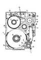
以下、本発明に係るテープカセットについて具体化した実施形態に基づいて図面を参照しつつ詳細に説明する。先ず、本実施形態に係るテープカセットの概略構成について図1に基づいて説明する。図1は本実施形態に係るテープカセットの透明な樹脂製のカバー1A(図3参照)を外した場合の平面図である。
図1に示すように、テープカセット1は透明テープ等からなる被印字テープ2、この被印字テープ2に印字を施すためのインクリボン9、更には、印字がなされた被印字テープ2に裏貼りされる両面粘着テープ12を各々、テープスプール3、リール8、テープスプール13に巻回して、カセット本体1Bの底面の裏側から嵌挿される後述のカセットボス部材37(図4参照)、カセット本体1Bの底面に立設されるリールボス16、及びカセット本体1Bの底面の裏側から嵌挿される後述のカセットボス部材32(図2、図3参照)に回転可能に挿入して収納したものであり、更に、使用済みのインクリボン9を巻き取るインクリボン巻取リール10を備えている。
【0026】
そして、前記リール8に巻回され、このリール8から引き出された未使用インクリボン9は、被印字テープ2と重ね合わされ、被印字テープ2と共に開口部18に入り、不図示の記録ヘッド及びプラテン間を通過する。その後、インクリボン9は、被印字テープ2から引き離され、後述のガイド部材50(図6参照)に沿って進行方向を約180度転換して、不図示のステップモータにより駆動されるインクリボン巻取リール10に至り、このインクリボン巻取リール10により巻き取られる。
【0027】
また、前記両面粘着テープ12は、片面に離形紙を重ね合わされた状態で、離形紙を外側にしてテープスプール13に巻回されて収納されている。そして、このテープスプール13から引き出された両面粘着テープ12は、テープ駆動ローラ19と不図示のテープ貼り合わせローラとの間を通過し、離形紙が重ね合わされない側の粘着面が被印字テープ2に貼着される。また、テープ駆動ローラ19の外周面から離れて走行しようとする両面粘着テープ12に接触する位置には、後述のように、両面粘着テープ12の粘着面とその幅にわたって接触する回転自在なガイドローラ44が、カセット本体1Bの底面の裏側から嵌挿される後述のガイド部材43に回転可能に貫装されている(図5参照)。尚、このガイドローラ44は、シリコンゴムによる一体成形品である。また、両面粘着テープ12の上下両端部には、不図示のスペーサが挿入されている。
【0028】
また、前記テープスプール3に巻回され、このテープスプール3から引き出された被印字テープ2は、不図示の被印字テープ2の終端部を検出するための終端検出用センサが挿入される一対の挿入部21の間、後述のガイド部材62(図8参照)、及び後述のガイド部材56を経由して、テープカセット1の開口部18を通過する。その後、両面粘着テープ12が貼り合わされる被印字テープ2は、テープカセット1の片側下方部(図1中、左下側部)に回転自在に設けられ、不図示のステップモータの駆動を受けて回転するテープ駆動ローラ19と、このテープ駆動ローラ19に対向配置される不図示のテープ貼り合わせローラとの間を通過して、テープカセット1の外部に送出される。この場合、両面粘着テープ12は、被印字テープ2に対してテープ駆動ローラ19及びテープ貼り合わせローラによって圧着される。
【0029】
また、両面粘着テープ12の斜め後方角部(図1中、左上角部)には、後述のように、係止部材67がカセット本体1Bの底面の裏側から嵌挿されている(図9参照)。さらに、被印字テープ2の斜め後方角部(図1中、右上角部)には、後述のように、係止部材72がカセット本体1Bの底面の裏側から嵌挿されている(図10参照)。
【0030】
そして、上記のように構成されたテープカセット本体1Bにカバー1Aを載置して、各カセットボス部材32、37、ガイド部材43、50、56、62、及び係止部材67、72に、後述のキャップ部材31、36、及び圧入部材42、49、55、61、66、71(図2乃至図10参照)を各々押し込むことにより、カバー1Aがテープカセット本体1Bに固設され、テープカセット1が組み立てられる。
【0031】
次に、両面粘着テープ12の上下から係止されるキャップ部材31とカセットボス部材32の取り付けについて図2及び図3に基づいて説明する。図2は本実施形態に係る両面粘着テープ12の上下から係止されるキャップ部材31とカセットボス部材32の斜視図で、(a)はキャップ部材31の斜視図、(b)はカセットボス部材32の斜視図である。図3は本実施形態に係る両面粘着テープ12の上下から係止されるキャップ部材31とカセットボス部材32の取り付けを示す要部を拡大した断面図で、(a)はキャップ部材31とカセットボス部材32の挿入前の断面図、(b)は組み立て後の断面図である。
【0032】
先ず、図2(a)に示すように、キャップ部材31は、略中空円筒状で、上端部は所定径の貫通孔が形成された円板により覆われている。この中空円筒の内径は、後述のカセットボス部材32の回転支持部32A(図2(b)参照)の外径よりも少し大きく形成されている。また、この上端面の下面には下方に垂設された2つの弾性係止片31Bがキャップ部材31の中心を挟んで対向するように設けられており、また、各弾性係止片31Bの下端には係止突起31Cが形成されている。この各係止突起31Cは、後述するカセットボス部材32に弾性的に係合される。さらに、円筒部分の下端面はカバー1Aに当接する押さえ部31Aを形成している。
【0033】
また、図2(b)に示すように、カセットボス部材32は、テープカセット1の厚さ寸法にほぼ等しい高さ寸法の略中空円筒状で、上端縁部の各係止突起31Cに対応する位置には各係止孔32Dが形成されている。そして、カセットボス部材32の下端周縁部には所定径のリブ32Bが形成され、このリブ32Bの上面には所定角度(本実施形態では、約90度)の間隔にテープカセット本体1Bの下面に当接する各押さえ突起32Cが形成されている。また、このカセットボス部材32の各係止孔32Dの下端部から各押さえ突起32Cの上端部は、後述のようにテープスプール13が遊嵌される回転支持部32Aを形成する。
【0034】
次に、このように形成されたキャップ部材31とカセットボス部材32の取り付けについて説明する。先ず、図3(a)に示すように、テープカセット本体1Bの底面裏側から所定高さ突設して形成された凹部34の貫通孔34Aの上側に、両面粘着テープ12が巻回されたテープスプール13を載置する。尚、この凹部34の内径は、カセットボス部材32のリブ32Bの外径より少し大きく形成され、この凹部34の深さは、カセットボス部材32の押さえ突起32Cの高さとほぼ等しく形成されている。また、この貫通孔34Aの直径は、カセットボス部材32の回転支持部32Aの外径よりも少し大きく、且つテープスプール13の外径より小さく形成されている。
そして、テープカセット本体1Bの底面裏側からカセットボス部材32を、前記貫通孔34Aに押さえ突起32Cが凹部34に当接するまで矢印35Bの方向に挿嵌すると共に、テープスプール13に挿嵌する。そして、両面粘着テープ12を引き出して、テープ引き出し経路に配置する。
【0035】
続いて、カバー1Aの上面から下方に所定深さ突設して形成された凹部33の貫通孔33Aを、カセットボス部材32に挿通させつつ、カバー1Aをテープカセット本体1Bに載置する。尚、凹部33の内径は、キャップ部材31の外径よりも少し大きく形成され、凹部33の上端から底面裏側までの寸法は、カバー1Aの高さ寸法にほぼ等しく形成されている。また、貫通孔33Aはカセットボス部材32の回転支持部32Aの外径よりも少し大きく形成されている。
そして、キャップ部材31の各係止突起31Cを、カセットボス部材32の各係止孔32Dに対向させつつ、キャップ部材31をカセットボス部材32に対して矢印35A方向に押し込む。
これにより、図3(b)に示すように、各係止突起31Cは、各係止孔32Dに弾性的に係合され、テープスプール13内においてキャップ部材31とカセットボス部材32との連結が行われると共に、キャップ部材31の押さえ部31Aが凹部33の底面に当接してカバー1Aをテープカセット本体1Bに押しつける。これにより、カバー1Aが、キャップ部材31とカセットボス部材32との連結により、テープカセット本体1Bの上側に固設されると共に、カセットボス部材32は、テープスプール13のカセットボスとして機能する。
【0036】
次に、被印字テープ2の上下から係止されるキャップ部材36とカセットボス部材37の取り付けについて図4に基づいて説明する。図4は本実施形態に係る被印字テープ2の上下から係止されるキャップ部材36とカセットボス部材37の取り付けを示す要部を拡大した断面図で、(a)はキャップ部材36とカセットボス部材37の挿入前の断面図、(b)は組み立て後の断面図である。
【0037】
先ず、図4(a)に示すように、キャップ部材36は、所定高さの断面が略コの字形の円筒で開口部が上側に向いている。この円筒部分の外径は、被印字テープ2が巻回されるテープスプール3の内径よりも少し小さく形成されている。また、この開口部の周縁にはカバー1Aに当接する所定径のリブ36Aが形成されている。また、その下面から下方に垂設された2つの弾性係止片36Bがキャップ部材36の中心を挟んで対向するように設けられており、また、各弾性係止片36Bの下端には係止突起36Cが形成されている。この各係止突起36Cは、後述するカセットボス部材37に弾性的に係合される。
【0038】
また、カセットボス部材37は、テープカセット1の厚さ寸法からキャップ部材36の円筒部分の高さ寸法を引いた寸法にほぼ等しい高さ寸法の略中空円筒状で、各係止突起36Cに対応する位置には各係止溝37Cが形成されている。そして、カセットボス部材37の下端周縁部にはテープカセット本体1Bに当接する所定径のリブ37Bが形成されている。また、このカセットボス部材37の上端からリブ37の上端面までは、後述のようにテープスプール3が遊嵌される回転支持部37Aを形成する。
【0039】
また、テープカセット本体1Bの底面の被印字テープ2の巻回されたテープスプール3が配置される位置には、貫通孔39が形成されている。この貫通孔39の直径は、テープスプール3の外径よりも小さく、且つカセットボス部材37の回転支持部37Aの外径よりも大きく形成されている。また、この貫通孔39の裏側端面の周縁には、カセットボス部材37のリブ37Bが当接する凹部39Aが形成されている。
【0040】
さらに、カバー1Aのテープスプール3に対向する位置には、貫通孔38が形成されている。この貫通孔38の直径は、テープスプール3の外径よりも小さく、且つキャップ部材36の円筒部分の外径よりも大きく形成されている。また、この貫通孔38の上側端面の周縁には、キャップ部材36のリブ36Aが当接する凹部38Aが形成されている。
【0041】
次に、このように形成されたキャップ部材36とカセットボス部材37の取り付けについて説明する。先ず、図4(a)に示すように、カセットボス部材37をテープカセット本体1Bの貫通孔39に下側から、リブ37Bが凹部39Aに当接するまで矢印40Bの方向に挿嵌する。そして、被印字テープ2が巻回されたテープスプール3をこのカセットボス部材37に、上側から矢印40Aの方向に挿嵌する。そして、被印字テープ2を引き出して、テープ引き出し経路に配置する。
【0042】
続いて、カバー1Aに形成された貫通孔38を、前記テープスプール3に対向させて、このカバー1Aを矢印40Aの方向に移動させ、テープカセット本体1Bに載置する。そして、キャップ部材36の各係止突起36Cを、カセットボス部材37の各係止溝37Cに対向させつつ、キャップ部材36をカセットボス部材37に対して矢印40A方向に押し込む。
これにより、図4(b)に示すように、各係止突起36Cは、各係止溝37Cに弾性的に係合され、テープスプール3内においてキャップ部材36とカセットボス部材37との連結が行われると共に、各リブ36A、37Bによってカバー1Aがテープカセット本体1Bに押しつけられる。これにより、カバー1Aが、キャップ部材36とカセットボス部材37との連結により、テープカセット本体1Bの上側に固設されると共に、キャップ部材36の円筒部分とカセットボス部材37の回転支持部37Aとは協動して、テープスプール3のカセットボスとして機能する。
【0043】
次に、ガイドローラ44の上下から圧入により装着される圧入部材42とガイド部材43の取り付けについて図5に基づいて説明する。図5は本実施形態に係るガイドローラ44の上下から圧入により装着される圧入部材42とガイド部材43の取り付けを示す要部を拡大した断面図で、(a)は圧入部材42とガイド部材43の圧入前の断面図、(b)は組み立て後の断面図である。
【0044】
先ず、図5(a)に示すように、ガイドローラ44Aは、略円筒状に形成されており、その外周面の軸方向に所定間隔で凸部44Aが形成されて、両面粘着テープ12の剥離性が高くなっている。また、ガイドローラ44Aの内径は、ガイド部材43の外径よりも少し大きく形成されている。
【0045】
また、圧入部材42は、丸い皿状の皿板部42Aから構成され、その下面の中心部には下方に垂設される所定径の圧入ピン42Bが設けられている。この皿板部42Aの厚さ寸法は、カバー1Aの厚さ寸法にほぼ等しく形成されている。また、皿板部42Aの下端面の直径は、ガイド部材43の上端面の直径にほぼ等しく形成されている。また、圧入ピン42Bは後述するガイド部材43の上端部に形成される軸孔43Cに圧入される。
【0046】
また、ガイド部材43は、テープカセット1の厚さ寸法からカバー1Aの厚さ寸法を引いた寸法にほぼ等しい高さ寸法の略円筒状で、軸断面が略H形に形成され、上端面及び下端面のほぼ中心に所定深さの軸孔43C、43Dが設けられている。この軸孔43Cの内径は、前記圧入ピン42Bの外径よりも少し小さく形成され、且つ軸孔43Cの深さ寸法はこの圧入ピン42Bの長さ寸法よりも大きく形成されている。そして、ガイド部材43の下端周縁部には、外側に傾斜した皿状の当接部43Bが形成されている。また、このガイド部材43の上端から当接部43Bの上端までは、後述のようにガイドローラ44が遊嵌される回転支持部43Aを形成する。
【0047】
また、テープカセット本体1Bの底面のガイドローラ44が配置される位置には、皿孔46が下面から上方向に形成されている。この皿孔46の内径は、ガイドローラ44の外径よりも小さく、且つガイド部材43の回転支持部43Aの外径よりも大きく形成されている。
さらに、カバー1Aのガイドローラ44に対向する位置には、皿孔45が形成されている。この皿孔45の皿状部の深さ寸法は、カバー1Aの厚さ寸法にほぼ等しく形成されている。また、皿孔45の下端部の直径は、圧入部材42の皿板部42Aの下端面の直径にほぼ等しく形成されている。
【0048】
次に、このように形成された圧入部材42とガイド部材43の取り付けについて説明する。先ず、図5(a)に示すように、ガイド部材43をテープカセット本体1Bの皿孔46に下側から、当接部43Bがテープカセット本体1Bに当接するまで矢印47Bの方向に挿嵌する。そして、ガイドローラ44をこのガイド部材43に、上側から矢印47Aの方向に挿嵌する。
【0049】
続いて、カバー1Aに形成された皿孔45を前記ガイド部材43の上端面に対向させて、このカバー1Aを矢印47Aの方向に移動させ、テープカセット本体1Bに載置する。そして、圧入部材42の圧入ピン42Bを、ガイド部材43の軸孔43Cに対向させつつ、圧入部材42をガイド部材43に対して矢印47A方向に押し込む。
これにより、図5(b)に示すように、圧入部材42の圧入ピン42Bは、ガイド部材43の軸孔43Cに圧入され、ガイドローラ44内において圧入部材42とガイド部材43の結合が行われると共に、圧入部材42はカバー1Aをテープカセット本体1Bに押しつける。これにより、カバー1Aが、圧入部材42とガイド部材43との結合により、テープカセット本体1Bの上側に固設されると共に、ガイド部材44は、ガイドローラ44を回転可能に支持するガイド軸として機能する。
【0050】
次に、インクリボン9をガイドするガイド部材50の取り付けについて図6に基づいて説明する。図6は本実施形態に係るインクリボンをガイドするガイド部材50の取り付けを示す要部を拡大した断面図である。
図6に示すように、圧入部材49、ガイド部材50、カバー1Aに形成される皿孔50、及びテープカセット本体1Bに形成される皿孔51の各構成は、上記ガイドローラ44を回転可能に支持する支軸を構成する圧入部材42、ガイド部材43、カバー1Aに形成される皿孔45、及びテープカセット本体1Bに形成される皿孔46の各構成とほぼ同じである。
但し、ガイド部材50は、その外周面の軸方向中央の周縁部に凸部50Aを形成するため、上端から少し下の位置及び下端部のテープカセット本体1Bの底面から少し上の位置から各々所定深さの凹部50Eが軸方向中央部に向かって所定長さ形成されている。
【0051】
次に、このように形成された圧入部材49とガイド部材50の取り付けについて説明する。先ず、図6に示すように、ガイド部材50をテープカセット本体1Bの皿孔51に下側から、当接部50Bがテープカセット本体1Bに当接するまで挿嵌する。そして、カバー1Aに形成された皿孔50を前記ガイド部材50の上端面に対向させて、このカバー1Aをテープカセット本体1Bに載置する。続いて、圧入部材49の圧入ピン49Bを、ガイド部材50の軸孔50Cに対向させつつ、圧入部材49をガイド部材50に対して押し込む。
これにより、図6に示すように、圧入部材49の圧入ピン49Bは、ガイド部材50の軸孔50Cに圧入され、圧入部材49とガイド部材50の結合が行われると共に、圧入部材49はカバー1Aをテープカセット本体1Bに押しつける。これにより、カバー1Aが、圧入部材49とガイド部材50との結合により、テープカセット本体1Bの上側に固設されると共に、ガイド部材50は、インクリボン9を所定方向に案内するガイド軸として機能する。また、ガイド部材50の外周面の軸方向の中央周縁部に形成される凸部50Aにより、インクリボン9の蛇行やしわの発生を防止することが可能となる。
【0052】
次に、被印字テープ2をガイドするガイド部材56の取り付けについて図7に基づいて説明する。図7は本実施形態に係る被印字テープ2をガイドするガイド部材56の取り付けを示す要部を拡大した断面図である。
図7に示すように、圧入部材55、ガイド部材56、カバー1Aに形成される皿孔57、及びテープカセット本体1Bに形成される皿孔58の各構成は、上記ガイドローラ44を回転可能に支持する支軸を構成する圧入部材42、ガイド部材43、カバー1Aに形成される皿孔45、及びテープカセット本体1Bに形成される皿孔46の各構成とほぼ同じである。
但し、ガイド部材56は、上端から少し下の位置から下端部のテープカセット本体1Bの底面から少し上の位置まで所定深さの凹部56Eが形成されて、該凹部56Eの上下端部に各テープガイド部56Aが設けられている。
【0053】
次に、このように形成された圧入部材55とガイド部材56の取り付けについて説明する。先ず、図7に示すように、ガイド部材56をテープカセット本体1Bの皿孔57に下側から、当接部56Bがテープカセット本体1Bに当接するまで挿嵌する。そして、カバー1Aに形成された皿孔57を前記ガイド部材56の上端面に対向させて、このカバー1Aをテープカセット本体1Bに載置する。続いて、圧入部材55の圧入ピン55Bを、ガイド部材56の軸孔56Cに対向させつつ、圧入部材55をガイド部材56に対して押し込む。
これにより、図7に示すように、圧入部材55の圧入ピン55Bは、ガイド部材56の軸孔56Cに圧入され、圧入部材55とガイド部材56の結合が行われると共に、圧入部材55はカバー1Aをテープカセット本体1Bに押しつける。これにより、カバー1Aが、圧入部材55とガイド部材56との結合により、テープカセット本体1Bの上側に固設されると共に、ガイド部材56は、被印字テープ2を所定方向に案内するガイド軸として機能する。また、ガイド部材56の上下端縁部に形成される各テープガイド部56Aにより、被印字テープ2の幅方向の移動を規制することが可能となる。
【0054】
次に、被印字テープ2をガイドするガイド部材62の取り付けについて図8に基づいて説明する。図8は本実施形態に係る被印字テープ2をガイドするガイド部材62の取り付けを示す要部を拡大した断面図である。
図8に示すように、圧入部材61、ガイド部材62、カバー1Aに形成される皿孔63、及びテープカセット本体1Bに形成される皿孔64の各構成は、上記ガイドローラ44を回転可能に支持する支軸を構成する圧入部材42、ガイド部材43、カバー1Aに形成される皿孔45、及びテープカセット本体1Bに形成される皿孔46の各構成とほぼ同じである。
但し、圧入部材61は、皿板部61Aの下端面が下方に所定長さ突設して、突設部61Cが形成されている。そして、この突設部61Cの下面のほぼ中心には垂設される所定径の圧入ピン61Bが設けられている。尚、皿板部61Aの下端面の直径は、後述のガイド部材62のテープカセット本体1Bの底面の位置の直径とほぼ同じである。
また、ガイド部材62は、テープカセット1の厚さ寸法から圧入部材61の上端面から突設部61Cの下端面までの高さ寸法を引いた寸法にほぼ等しい高さ寸法に形成されている。そして、ガイド部材62は、上端から下端部のテープカセット本体1Bの底面から少し上の位置まで所定深さの凹部62Eが形成されて、該凹部62Eの下端部にテープガイド部62Aが設けられている。
【0055】
次に、このように形成された圧入部材61とガイド部材62の取り付けについて説明する。先ず、図8に示すように、ガイド部材62をテープカセット本体1Bの皿孔64に下側から、当接部62Bがテープカセット本体1Bに当接するまで挿嵌する。そして、カバー1Aに形成された皿孔63を前記ガイド部材62の上端面に対向させて、このカバー1Aをテープカセット本体1Bに載置する。続いて、圧入部材61の圧入ピン61Bを、ガイド部材62の軸孔62Cに対向させつつ、圧入部材61をガイド部材62に対して押し込む。
これにより、図8に示すように、圧入部材61の圧入ピン61Bは、ガイド部材62の軸孔62Cに圧入され、圧入部材61とガイド部材62の結合が行われると共に、圧入部材61はカバー1Aをテープカセット本体1Bに押しつける。これにより、カバー1Aが、圧入部材61とガイド部材62との結合により、テープカセット本体1Bの上側に固設されると共に、ガイド部材62は、被印字テープ2を所定方向に案内するガイド軸として機能する。また、圧入部材61の突設部61Cの下端面とガイド部材62の上端周縁部との協動により上側のテープガイド部65が形成され、このテープガイド部65とガイド部材62の下端縁部に形成されるテープガイド部62Aとにより、被印字テープ2の幅方向の移動を規制することが可能となる。
【0056】
次に、カバー1Aとテープカセット本体1Bとを係止する係止部材67の取り付けについて図9に基づいて説明する。図9は本実施形態に係るカバー1Aとテープカセット本体1Bとを係止する係止部材67の取り付けを示す要部を拡大した断面図である。
図9に示すように、圧入部材66、係止部材67、カバー1Aに形成される皿孔68、及びテープカセット本体1Bに形成される皿孔69の各構成は、上記ガイドローラ44を回転可能に支持する支軸を構成する圧入部材42、ガイド部材43、カバー1Aに形成される皿孔45、及びテープカセット本体1Bに形成される皿孔46の各構成とほぼ同じである。
【0057】
次に、このように形成された圧入部材66と係止部材67の取り付けについて説明する。先ず、図9に示すように、係止部材67をテープカセット本体1Bの皿孔69に下側から、当接部67Bがテープカセット本体1Bに当接するまで挿嵌する。そして、カバー1Aに形成された皿孔68を前記係止部材67の上端面に対向させて、このカバー1Aをテープカセット本体1Bに載置する。続いて、圧入部材66の圧入ピン66Bを、係止部材67の軸孔67Cに対向させつつ、圧入部材66を係止部材67に対して押し込む。
これにより、図9に示すように、圧入部材66の圧入ピン66Bは、係止部材67の軸孔67Cに圧入され、圧入部材66と係止部材67の結合が行われると共に、圧入部材66はカバー1Aをテープカセット本体1Bに押しつける。これにより、カバー1Aが、圧入部材66と係止部材67との結合により、テープカセット本体1Bの上側に固設される。
【0058】
次に、カバー1Aとテープカセット本体1Bとを係止する係止部材72の取り付けについて図10に基づいて説明する。図10は本実施形態に係るカバー1Aとテープカセット本体1Bとを係止する係止部材72の取り付けを示す要部を拡大した断面図である。
【0059】
先ず、圧入部材71は、円板状の円板部71Aから構成され、その下面の中心部には下方に垂設される所定径の圧入ピン71Bが設けられている。また、この円板部71Aの上端周縁部には所定径のリブ71Cが形成されている。このリブ71Cの厚さ寸法は、カバー1Aの厚さ寸法よりも小さく形成されている。また、円板部71Aの厚さ寸法は、カバー1Aの厚さ寸法より少し大きく形成されている。また、円板部71Aの下端面の直径は、係止部材72の上端面の直径にほぼ等しく形成されている。また、圧入ピン71Bは後述するガイド部材72の上端部に形成される軸孔72Bに圧入される。
【0060】
また、係止部材72は、テープカセット1の厚さ寸法から圧入部材71の円板部71Aの厚さ寸法を引いた寸法にほぼ等しい高さ寸法の略中空円筒状で、下端面が所定厚さ塞がれて、軸断面が略コの字形に形成されている。また、下端周縁部には所定径のリブ72Aが形成されている。このリブ72Aの厚さ寸法は、テープカセット本体1Bの底面厚さ寸法よりも小さく形成されている。また、上端面のほぼ中心に所定深さの軸孔72Bが設けられている。この軸孔72Bの内径は、前記圧入ピン71Bの外径よりも少し小さく形成され、且つ軸孔72Bの深さ寸法はこの圧入ピン71Bの長さ寸法よりも大きく形成されている。
【0061】
また、テープカセット本体1Bの係止部材72が配置される位置には、中空円筒状のポスト74が立設されている。このポスト74の高さ寸法は、カバー1Aの底面にほぼ当接する高さ寸法である。また、このポスト74の内径は、係止部材72の外径よりも少し大きく形成されている。また、このポスト74に対向するテープカセット本体1Bの下面側には、係止部材72のリブ72Aが嵌入される凹部75が形成されている。
さらに、カバー1Aの係止部材72に対向する位置には、貫通孔73が形成されている。この貫通孔73の直径は、圧入部材71の円板部71Aの直径よりも少し大きく形成されている。また、この貫通孔73の上端周縁部には、圧入部材71のリブ71Cが嵌入される凹部73Aが形成されている。
【0062】
次に、このように形成された圧入部材71と係止部材72の取り付けについて説明する。先ず、図10に示すように、係止部材72をテープカセット本体1Bのポスト74に下側から、リブ72Aがテープカセット本体1Bに当接するまで挿嵌する。そして、カバー1Aに形成された貫通孔73を前記係止部材72の上端面に対向させて、このカバー1Aをテープカセット本体1Bに載置する。続いて、圧入部材71の圧入ピン71Bを、係止部材72の軸孔72Bに対向させつつ、圧入部材71を係止部材72に対して押し込む。
これにより、図10に示すように、圧入部材71の圧入ピン71Bは、係止部材72の軸孔72Bに圧入され、圧入部材71と係止部材72の結合が行われると共に、圧入部材71はカバー1Aをテープカセット本体1Bに押しつける。これにより、カバー1Aが、圧入部材71と係止部材72との結合により、テープカセット本体1Bの上側に固設される。
【0063】
次に、各キャップ部材31、36と各カセットボス部材32、37との分離について図11に基づいて説明する。図11は本実施形態に係るテープカセット1のキャップ部材31とカセットボス部材32との分離の一例を示す要部を拡大した断面図で、(a)はキャップ部材31とカセットボス部材32との結合部の削除を模式的に示す断面図、(b)はキャップ部材31とカセットボス部材32との分離を示す断面図である。
先ず、テープカセット1のキャップ部材31とカセットボス部材32との分離について説明する。図11(a)に示すように、テープカセット1を切削台等の上に固定し、エンドミル81を回転させつつキャップ部材31の上側から矢印82の方向に、エンドミル81の先端がキャップ部材31の下端面より少し下側に位置するまで降ろし、キャップ部材31の上面部、各弾性係止片31Bの上端部、及びカセットボス部材32の上端部を切削により除去する。そして、エンドミル81を上方に移動させ、エンドミル81の回転を停止する。尚、このエンドミル81の外径は、キャップ部材31の上端面の直径より小さく、且つ、カセットボス部材32の上端面の外径よりも大きく形成されている。
【0064】
そして、図11(b)に示すように、テープカセット1を切削台等から取り外し、キャップ部材31を上方向(矢印83Aの方向)に取り除く。また、カセットボス部材32を各係止孔32D内に各係止片31Bを係着させたまま、テープカセット本体1Bの下側方向(矢印83B方向)に抜き去る。これにより、カバー1Aを上方向(矢印83A方向)に分離することが可能となる。さらに、両面粘着テープ12が巻回されたテープスプール13をテープカセット本体1Bから取り除くことが可能となり、新しい両面粘着テープを装着することが可能となる。
【0065】
同様に、テープカセット1のキャップ部材36とカセットボス部材37との分離は、テープカセット1を切削台等の上に固定し、エンドミルを回転させつつキャップ部材36の上側から、エンドミルの先端がキャップ部材36の下端面より少し下側に位置するまで降ろし、キャップ部材36の底面部、各弾性係止片36Bの上端部、及びカセットボス部材37の上端部を切削により除去する。そして、このエンドミルを上方に移動させ、エンドミルの回転を停止する。尚、このエンドミルの外径は、キャップ部材36の円筒部分の外径及びカセットボス部材37の上端部の外径よりも小さく、且つキャップ部材36の各弾性係止片36Bの上端延出部の外径よりも大きく形成されている。
そして、テープカセット1を切削台等から取り外し、キャップ部材36を上方向に取り除く。また、カセットボス部材37を各係止溝37C内に各弾性係止片36Bを係着させたまま、テープカセット本体1Bの下側方向に抜き去る。これにより、カバー1Aとテープカセット本体1Bとを分離することが可能となる。さらに、被印字テープ2が巻回されたテープスプール3をテープカセット本体1Bから取り除くことが可能となり、新しい被印字テープを装着することが可能となる。
【0066】
次に、各圧入部材42、49、55、61、66、71と各ガイド部材43、50、56、62、及び各係止部材67、72との分離について図12に基づいて説明する。図12は本実施形態に係るテープカセット1の圧入部材42とガイド部材43との分離の一例を示す要部を拡大した断面図で、(a)は圧入部材42とガイド部材43との結合部の削除を模式的に示す断面図、(b)は圧入部材42とガイド部材43との分離を示す断面図である。
先ず、テープカセット1の圧入部材42とガイド部材43との分離について説明する。図12(a)に示すように、テープカセット1を切削台等の上に固定し、エンドミル85を回転させつつ圧入部材42の上側から矢印86の方向に、エンドミル85の先端が圧入部材42の皿板部42Aの下端面より少し下側に位置するまで降ろし、皿板部42Aのほぼ中央部分、圧入ピン42Bの上端部、及びガイド部材43の上端部を切削により除去する。そして、エンドミル85を上方に移動させ、エンドミル85の回転を停止する。尚、このエンドミル85の外径は、ガイド部材43の上端面の外径よりも小さく、且つ圧入ピン42Bの外径よりも大きく形成されている。
【0067】
そして、図12(b)に示すように、テープカセット1を切削台等から取り外し、圧入部材42を上方向(矢印87の方向)に取り除く。また、ガイド部材43を軸孔43C内に圧入ピン42Bを嵌着させたまま、テープカセット本体1Bの下側方向(矢印88方向)に抜き去る。これにより、カバー1Aを上方向(矢印87方向)に分離することが可能となる。さらに、ガイドローラ44をテープカセット本体1Bから取り除くことが可能となり、このガイドローラ44の洗浄や取り換えが可能となる。
【0068】
同様に、各圧入部材49、55、61、66、71と各ガイド部材50、56、62、及び各係止部材67、72との分離は、テープカセット1を切削台等の上に固定し、エンドミルを回転させつつ各圧入部材49、55、61、66、71の上側から、エンドミルの先端が各圧入部材49、55、61、66、71の各皿板部49A、55A、61A、66A、及び円板部71Aの下端面より少し下側に位置するまで降ろし、各皿板部49A、55A、61A、66A、及び円板部71Aのほぼ中央部分、各圧入ピン49B、55B、61B、66B、71Bの上端部、及び各ガイド部材50、56、62、及び各係止部材67、72の上端部を切削により除去する。そして、エンドミルを上方に移動させ、エンドミルの回転を停止する。尚、このエンドミルの外径は、各ガイド部材50、56、62、及び各係止部材67、72の上端面の外径よりも小さく、且つ各圧入ピン49B、55B、61B、66B、71Bの外径よりも大きく形成されている。
そして、テープカセット1を切削台等から取り外し、各圧入部材49、55、61、66、71を上方向に取り除く。また、各ガイド部材50、56、62、及び各係止部材67、72の軸孔50C、56C、62C、67C、72Bに各圧入ピン49B、55B、61B、66B、71Bを嵌着させたまま、テープカセット本体1Bの下側方向に抜き去る。これにより、カバー1Aとテープカセット本体1Bとを分離することが可能となる。
【0069】
ここで、テープカセット本体1Bは、カセットケース本体を構成する。また、カバー1Aは蓋部材を構成する。また、各キャップ部材31、36、及び各圧入部材42、49、55、61、66、71は、上嵌合部材として機能する。また、各カセットボス部材32、37、各ガイド部材43、50、56、62、及び各係止部材67、72は、下嵌合部材として機能する。また、各係止溝37Cは係止孔として機能する。さらに、テープガイド部56A、62A、65は、幅ガイド部を構成する。
【0070】
以上詳細に説明した通り本実施形態に係るテープカセット1では、テープカセット本体1Bの下面より、各カセットボス部材32、37、各ガイド部材43、50、56、62、及び各係止部材67、72を各貫通孔34A、39、各皿孔46、51、58、64、69、及びポスト74に嵌挿する。そして、カセットボス部材32に両面粘着テープ12が巻回されたテープスプール13を遊嵌し、また、カセットボス部材37に被印字テープ2が巻回されたテープスプール3を遊嵌し、さらに、ガイド部材43にガイドローラ44を遊嵌する。続いて、インクリボン9を装着すると共に、両面粘着テープ12及び被印字テープ2を引き出し、カバー1Aをテープカセット本体1Bに載置する。そして、各カセットボス部材32、37の上側から各キャップ部材31、36を押し込み、弾性的に係合させる。また、各ガイド部材43、50、56、62、及び各係止部材67、72の上側から各圧入部材42、49、55、61、66、71を押し込み、圧入して結合する。これにより、カバー1Aはテープカセット本体1Bに固設される。
また、テープカセット1を切削台等の上に固定し、エンドミル81等により、このテープカセット1の上側から各キャップ部材31、36の各弾性係止片31B、36B、及び各カセットボス部材32、37の上端部を切削により除去する。また、エンドミル85等によりこのテープカセット1の上側から各圧入部材42、49、55、61、66、71の各圧入ピン42B、49B、55B、61B、66B、71B、及び各ガイド部材43、50、56、62、及び各係止部材67、72の上端部を切削により除去する。これにより、カバー1Aはテープカセット本体1Bから分離可能となる。
【0071】
したがって、各キャップ部材31、36と各カセットボス部材32、37との結合、及び各圧入部材42、49、55、61、66、71と各ガイド部材43、50、56、62、及び各係止部材67、72との結合の削除には、エンドミル81、85等の特殊な治具が必要になるため、ユーザーは当該テープカセットを容易に分解することはできないが、回収再利用の場合においては、メーカ側においてカバー1Aとテープカセット本体1Bとを傷つけることなく容易に分離し、各部品を再利用することが可能となる。
また、各キャップ部材31、36と各カセットボス部材32、37とは、弾性的係合により結合され、各圧入部材42、49、55、61、66、71と各ガイド部材43、50、56、62、及び各係止部材67、72とは、圧入により嵌着されるため、組み立てが容易になり、製造コストダウンを図ることが可能となる。
また、各テープスプール3、13との摩擦等によって傷つく各カセットボス部材32、37や、各テープ2、9、12の走行等により傷つく各ガイド部材43、50、56、62を再利用毎に交換することができるため、カバー1Aとテープカセット本体1Bとの再利用回数を飛躍的に多くすることが可能となると共に、各テープ2、9、12の引き出し負荷を常に低くすることが可能となる。また、各ガイド部材43、50、56、62の表面の傷等による各テープ2、9、12の損傷を防止することが可能となる。
また、圧入部材55、61とガイド部材56、62とにより構成されるガイド軸は、被印字テープ2の幅方向の移動を規制する各テープガイド部56A、62A、65が形成されているため、被印字テープ2の蛇行を防止することが可能となる。
また、ガイド部材50の外周面軸方向のほぼ中央部分に所定高さの凸部50Aが円周方向に形成されているため、インクリボン9の蛇行を防止することが可能となると共に、表面のしわの発生を防止することが可能となる。
さらに、ガイド部材43は、両面粘着テープ12の粘着面に対して剥離性を備えた外周面を有するガイドローラ44が回転可能に遊嵌されているため、両面粘着テープ12に接触したガイドローラ44は、該両面粘着テープ12の走行に伴って回転し、両面粘着テープ12から容易に剥がれることが可能となると共に、両面粘着テープのスムーズな送り出しが可能となる。また、ガイドローラ44は、外周面の軸方向に所定間隔で凸部44Aが円周方向に形成されているため、両面粘着テープ12に対する剥離性の向上を図ることが可能となると共に、両面粘着テープ12のよりスムーズな送り出しが可能となる。
【0072】
尚、本発明は前記実施形態に限定されることはなく、本発明の要旨を逸脱しない範囲内で種々の改良、変形が可能であることは勿論である。
【0073】
【発明の効果】
以上説明した通り本発明は、カセットケース本体とこのカセットケース本体に載置される蓋部材とが各々に形成された貫通孔に挿入される上嵌合部材と下嵌合部材との結合により、カセットケース本体に蓋部材が固設され、また、上嵌合部材と下嵌合部材との結合を特殊治具によって破壊すると、このカセットケース本体と蓋部材とにダメージを与えること無く分離することができるため、使用済みテープカセットの各テープを詰め替えて再利用することが可能なテープカセットを提供することができる。
【図面の簡単な説明】
【図1】 本実施形態に係るテープカセットの透明な樹脂製のカバーを外した場合の平面図である。
【図2】 本実施形態に係る両面粘着テープの上下から係止されるキャップ部材とカセットボス部材の斜視図で、(a)はキャップ部材の斜視図、(b)はカセットボス部材の斜視図である。
【図3】 本実施形態に係る両面粘着テープの上下から係止されるキャップ部材とカセットボス部材の取り付けを示す要部を拡大した断面図で、(a)はキャップ部材とカセットボス部材の挿入前の断面図、(b)は組み立て後の断面図である。
【図4】 本実施形態に係る被印字テープの上下から係止されるキャップ部材とカセットボス部材の取り付けを示す要部を拡大した断面図で、(a)はキャップ部材とカセットボス部材の挿入前の断面図、(b)は組み立て後の断面図である。
【図5】 本実施形態に係るガイドローラの上下から圧入により装着される圧入部材とガイド部材の取り付けを示す要部を拡大した断面図で、(a)は圧入部材とガイド部材の圧入前の断面図、(b)は組み立て後の断面図である。
【図6】 本実施形態に係るインクリボンをガイドするガイド部材の取り付けを示す要部を拡大した断面図である。
【図7】 本実施形態に係る被印字テープ2をガイドするガイド部材の取り付けを示す要部を拡大した断面図である。
【図8】 本実施形態に係る被印字テープをガイドするガイド部材の取り付けを示す要部を拡大した断面図である。
【図9】 本実施形態に係るカバーとテープカセット本体とを係止する係止部材の取り付けを示す要部を拡大した断面図である。
【図10】 本実施形態に係るカバーとテープカセット本体とを係止する係止部材の取り付けを示す要部を拡大した断面図である。
【図11】 本実施形態に係るテープカセットのキャップ部材とカセットボス部材との分離の一例を示す要部を拡大した断面図で、(a)はキャップ部材とカセットボス部材との結合部の削除を模式的に示す断面図、(b)はキャップ部材とカセットボス部材との分離を示す断面図である。
【図12】 本実施形態に係るテープカセットの圧入部材とガイド部材との分離の一例を示す要部を拡大した断面図で、(a)は圧入部材とガイド部材との結合部の削除を模式的に示す断面図、(b)は圧入部材とガイド部材との分離を示す断面図である。
【符号の説明】
1 テープカセット
1A カバー
1B テープカセット本体
2 被印字テープ
3、13 テープスプール
9 インクリボン
12 両面粘着テープ
31、36 キャップ部材
32、37 カセットボス部材
42、49、55、61、66、71 圧入部材
43、50、56、62 ガイド部材
67、72 係止部材
74 ポスト
81、85 エンドミル[0001]
BACKGROUND OF THE INVENTION
The present invention relates to a tape cassette used in a tape printer, and in particular, an upper fitting member into which a cassette case main body and a lid member placed on the cassette case main body are inserted into through holes formed respectively. A lid member is fixed to the cassette case main body due to the coupling with the lower fitting member, and when the coupling between the upper fitting member and the lower fitting member is broken by a special jig, the cassette case main body and the lid member are The present invention relates to a tape cassette that can be separated and reused by refilling each tape of a used tape cassette.
[0002]
[Prior art]
2. Description of the Related Art Conventionally, in a tape printer that prints characters such as characters on a print-receiving tape, which is a long print medium, a cassette having a predetermined shape includes a print-receiving tape and an ink ribbon for printing on the print-receiving tape. The tape cassette housed in the case is attached to the printing mechanism, and the print tape supplied from the tape cassette and the ink ribbon are superposed to print characters and the like through a thermal head to create a tape with letters. It is configured as follows.
[0003]
As the print-receiving tape stored in the tape cassette, a transparent film tape formed in a predetermined width, a tape having a release paper attached to one side of the film tape via an adhesive, and a thermosensitive tape having self-coloring properties (So-called thermal paper) and the like exist, and all of these tapes are stored in a cassette case body of a tape cassette in a state of being wound around a tape spool.
[0004]
Then, after the tape is stored in the cassette body, the cassette case body is fixed by the cassette cover being welded or press-fitted with a pin. When characters or the like are printed on the print-receiving tape as described above, the print-receiving tape is sequentially pulled out from the tape spool, and finally the end tape is pulled out from the tape spool. When the end tape is pulled out, the used tape cassette can be easily removed from the tape printer and a new tape cassette can be set quickly.
[0005]
[Problems to be solved by the invention]
However, even though the used tape cassette has been used and the shape and function of the cassette case main body are not impaired, the cassette case main body is fixed with a cassette cover welded or press-fitted with a pin. Therefore, if the cassette case body and the cassette cover are separated, there is a problem that the cassette case body and the cassette cover are destroyed and cannot be reused.
[0006]
Accordingly, the present invention has been made to solve the above-described problems, and the cassette case main body and the lid member placed on the cassette case main body are inserted into the through holes formed in each. When the fitting member and the lower fitting member are joined, a lid member is fixed to the cassette case body, and when the upper fitting member and the lower fitting member are broken by a special jig, the cassette case body An object of the present invention is to provide a tape cassette that can be re-used by refilling each tape of a used tape cassette.
[0007]
[Means for Solving the Problems]
To achieve the above object, a tape cassette according to
[0008]
According to the tape cassette according to
As a result, a special jig is required to delete the connection between the upper fitting member and the lower fitting member, so the user cannot easily disassemble the tape cassette. In this case, the manufacturer can easily separate the cassette case main body and the lid member without damaging them, and can reuse each component.In addition, since the guide shaft of the tape running that is damaged by friction with the tape or the like can be replaced every time it is reused, it is possible to dramatically increase the number of times the cassette case body and the lid member are reused, It is possible to prevent damage caused by friction with the guide shaft of the tape.
[0009]
The tape cassette according to
[0010]
According to the tape cassette according to
[0011]
[0012]
[0013]
[0014]
[0015]
[0016]
[0017]
Claims3The tape cassette according to claim1 or claim 2In the tape cassette described above, the guide shaft is formed with a width guide portion that restricts movement of the tape in the width direction.
[0018]
Claims having such characteristics3According to the tape cassette according to claim1 or claim 2In the tape cassette described above, since the guide shaft is formed with a width guide portion that restricts movement of the tape in the width direction, the meandering of the tape can be prevented.
[0019]
Claims4The tape cassette according to claim1 toClaimOne of 3The guide cassette is characterized in that a convex portion having a predetermined height is formed in the circumferential direction at a substantially central portion in the outer peripheral surface axial direction.
[0020]
Claims having such characteristics4According to the tape cassette according to claim1 toClaimOne of 3In the tape cassette according to the above, the guide shaft has a convex portion formed in a circumferential direction at a substantially central portion in the axial direction of the outer peripheral surface, so that it is possible to prevent meandering of the tape. It is possible to prevent wrinkles on the tape surface.
[0021]
Claims5The tape cassette according to claimAny one of
[0022]
Claims having such characteristics5According to the tape cassette according to claimAny one of
[0023]
And claims6The tape cassette according to claim5In the tape cassette described above, the guide roller is characterized in that convex portions are formed in the circumferential direction at predetermined intervals in the axial direction of the outer peripheral surface.
[0024]
Claims having such characteristics6According to the tape cassette according to claim5In the tape cassette described in the above, the guide roller has convex portions formed in the circumferential direction at predetermined intervals in the axial direction of the outer peripheral surface, and thus it is possible to improve the peelability to the adhesive tape, Smoother feeding of the adhesive tape is possible.
[0025]
DETAILED DESCRIPTION OF THE INVENTION
DETAILED DESCRIPTION Hereinafter, a tape cassette according to the present invention will be described in detail with reference to the drawings based on an embodiment that is embodied. First, a schematic configuration of the tape cassette according to the present embodiment will be described with reference to FIG. FIG. 1 is a plan view of the tape cassette according to the present embodiment when the
As shown in FIG. 1, a
[0026]
Then, the unused ink ribbon 9 wound around the
[0027]
The double-sided pressure-
[0028]
The print-receiving
[0029]
Further, as described later, a locking
[0030]
Then, the
[0031]
Next, attachment of the
[0032]
First, as shown in FIG. 2A, the
[0033]
As shown in FIG. 2B, the
[0034]
Next, attachment of the
Then, the
[0035]
Subsequently, the
Then, the
As a result, as shown in FIG. 3B, each locking
[0036]
Next, attachment of the
[0037]
First, as shown in FIG. 4A, the
[0038]
The
[0039]
Further, a through
[0040]
Further, a through
[0041]
Next, attachment of the
[0042]
Subsequently, the through-
As a result, as shown in FIG. 4B, each locking
[0043]
Next, attachment of the press-fitting
[0044]
First, as shown in FIG. 5A, the guide roller 44A is formed in a substantially cylindrical shape, and convex portions 44A are formed at predetermined intervals in the axial direction of the outer peripheral surface thereof, so that the double-sided
[0045]
The press-fitting
[0046]
The
[0047]
Further, a
Further, a
[0048]
Next, attachment of the press-fitting
[0049]
Subsequently, the
5B, the press-
[0050]
Next, attachment of the
As shown in FIG. 6, each of the press-fitting
However, since the
[0051]
Next, attachment of the press-fitting
As a result, as shown in FIG. 6, the press-fit pin 49B of the press-
[0052]
Next, attachment of the
As shown in FIG. 7, each of the press-fitting
However, the
[0053]
Next, attachment of the press-fitting
Accordingly, as shown in FIG. 7, the press-
[0054]
Next, attachment of the
As shown in FIG. 8, each of the press-fitting
However, the press-fitting
The
[0055]
Next, attachment of the press-fitting
As a result, as shown in FIG. 8, the press-fit pin 61B of the press-
[0056]
Next, attachment of the locking
As shown in FIG. 9, each structure of the press-fitting
[0057]
Next, attachment of the press-fitting
As a result, as shown in FIG. 9, the press-
[0058]
Next, attachment of the locking
[0059]
First, the press-fitting
[0060]
The locking
[0061]
A hollow
Further, a through
[0062]
Next, attachment of the press-fitting
As a result, as shown in FIG. 10, the press-fit pin 71B of the press-
[0063]
Next, separation of the
First, separation of the
[0064]
Then, as shown in FIG. 11B, the
[0065]
Similarly, the
Then, the
[0066]
Next, separation of the press-fitting
First, separation of the press-fitting
[0067]
Then, as shown in FIG. 12B, the
[0068]
Similarly, the press-fitting
Then, the
[0069]
Here, the
[0070]
As described above in detail, in the
Further, the
[0071]
Therefore, the
Further, the
In addition, the
Further, since the guide shaft constituted by the press-fitting
In addition, since the
Further, since the
[0072]
In addition, this invention is not limited to the said embodiment, Of course, various improvement and deformation | transformation are possible within the range which does not deviate from the summary of this invention.
[0073]
【The invention's effect】
As described above, the present invention is a combination of the upper fitting member and the lower fitting member inserted into the through holes formed in the cassette case main body and the lid member placed on the cassette case main body, A lid member is fixed to the cassette case body, and when the connection between the upper fitting member and the lower fitting member is broken by a special jig, the cassette case body and the lid member are separated without damaging them. Therefore, it is possible to provide a tape cassette capable of refilling and reusing each tape of the used tape cassette.
[Brief description of the drawings]
FIG. 1 is a plan view when a transparent resin cover of a tape cassette according to the present embodiment is removed.
2A and 2B are perspective views of a cap member and a cassette boss member that are locked from above and below the double-sided pressure-sensitive adhesive tape according to the present embodiment, wherein FIG. 2A is a perspective view of the cap member, and FIG. 2B is a perspective view of the cassette boss member. It is.
FIG. 3 is an enlarged cross-sectional view of a main part showing attachment of a cap member and a cassette boss member locked from above and below of the double-sided pressure-sensitive adhesive tape according to the present embodiment, and (a) is an insertion of the cap member and the cassette boss member. A front sectional view, (b) is a sectional view after assembly.
FIG. 4 is an enlarged cross-sectional view of a main part showing attachment of a cap member and a cassette boss member which are locked from above and below the tape to be printed according to the present embodiment, and (a) is an insertion of the cap member and the cassette boss member. A front sectional view, (b) is a sectional view after assembly.
FIG. 5 is an enlarged cross-sectional view of a main part showing the press-fitting member to be attached by press-fitting from above and below the guide roller according to the present embodiment and the attachment of the guide member, (a) before press-fitting of the press-fitting member and the guide member Sectional drawing, (b) is sectional drawing after an assembly.
FIG. 6 is an enlarged cross-sectional view of a main part showing attachment of a guide member for guiding the ink ribbon according to the present embodiment.
FIG. 7 is an enlarged cross-sectional view of a main part showing attachment of a guide member for guiding the print-receiving
FIG. 8 is an enlarged cross-sectional view of a main part showing attachment of a guide member for guiding the print-receiving tape according to the present embodiment.
FIG. 9 is an enlarged cross-sectional view of a main part showing attachment of a locking member for locking the cover and the tape cassette main body according to the present embodiment.
FIG. 10 is an enlarged cross-sectional view of a main part showing attachment of a locking member for locking the cover and the tape cassette body according to the present embodiment.
FIG. 11 is an enlarged cross-sectional view showing a main part showing an example of separation between the cap member and the cassette boss member of the tape cassette according to the present embodiment, in which (a) is a deletion of a connecting portion between the cap member and the cassette boss member. FIG. 5B is a cross-sectional view schematically showing separation of the cap member and the cassette boss member.
FIG. 12 is an enlarged cross-sectional view of a main part illustrating an example of separation between the press-fitting member and the guide member of the tape cassette according to the present embodiment, and FIG. 12 (a) schematically illustrates the deletion of the connecting portion between the press-fitting member and the guide member. (B) is sectional drawing which shows isolation | separation of a press-fit member and a guide member.
[Explanation of symbols]
1 Tape cassette
1A cover
1B Tape cassette body
2 Printed tape
3, 13 Tape spool
9 Ink ribbon
12 Double-sided adhesive tape
31, 36 Cap member
32, 37 Cassette boss member
42, 49, 55, 61, 66, 71 Press-fit member
43, 50, 56, 62 Guide member
67, 72 Locking member
74 posts
81, 85 End mill
Claims (6)
Translated fromJapaneseカセットケース本体と、
前記カセットケース本体に載置される蓋部材と、
前記蓋部材に形成された複数の貫通孔に上側から挿入される複数の上嵌合部材と、
前記カセットケース本体の前記貫通孔に対向する位置に形成された複数の貫通孔に下側から挿入される複数の下嵌合部材とを備え、
前記蓋部材は、前記上嵌合部材と下嵌合部材との結合によって前記カセットケース本体に固設されると共に、前記上嵌合部材と下嵌合部材との結合部分の削除によって前記カセットケース本体から分離可能になり、
前記上嵌合部材と下嵌合部材との結合によってテープの走行をガイドするガイド軸が形成されることを特徴とするテープカセット。In tape cassettes used for tape printers,
The cassette case body,
A lid member placed on the cassette case body;
A plurality of upper fitting members inserted from above into a plurality of through holes formed in the lid member;
A plurality of lower fitting members inserted from below into a plurality of through holes formed at positions facing the through holes of the cassette case body,
The lid member is fixed to the cassette case main body by the coupling of the upper fitting member and the lower fitting member, and the cassette case is removed by deleting the coupling portion between the upper fitting member and the lower fitting member.Ri name to be separable from thebody,
Tape cassette according to claim Rukotoguide shaft for guiding the running of the tape is formed by coupling with the upper fitting member and the lower fitting member.
Priority Applications (1)
| Application Number | Priority Date | Filing Date | Title |
|---|---|---|---|
| JP27265398AJP3882360B2 (en) | 1998-09-28 | 1998-09-28 | Tape cassette |
Applications Claiming Priority (1)
| Application Number | Priority Date | Filing Date | Title |
|---|---|---|---|
| JP27265398AJP3882360B2 (en) | 1998-09-28 | 1998-09-28 | Tape cassette |
Publications (2)
| Publication Number | Publication Date |
|---|---|
| JP2000103129A JP2000103129A (en) | 2000-04-11 |
| JP3882360B2true JP3882360B2 (en) | 2007-02-14 |
Family
ID=17516930
Family Applications (1)
| Application Number | Title | Priority Date | Filing Date |
|---|---|---|---|
| JP27265398AExpired - Fee RelatedJP3882360B2 (en) | 1998-09-28 | 1998-09-28 | Tape cassette |
Country Status (1)
| Country | Link |
|---|---|
| JP (1) | JP3882360B2 (en) |
Cited By (2)
| Publication number | Priority date | Publication date | Assignee | Title |
|---|---|---|---|---|
| CN102295197A (en)* | 2010-06-25 | 2011-12-28 | 精工爱普生株式会社 | With cassette and with printing unit |
| CN102390186A (en)* | 2010-07-16 | 2012-03-28 | 精工爱普生株式会社 | Tape placement apparatus and tape printer provided therewith |
Families Citing this family (27)
| Publication number | Priority date | Publication date | Assignee | Title |
|---|---|---|---|---|
| EP2965916B1 (en) | 2008-12-25 | 2021-03-03 | Brother Kogyo Kabushiki Kaisha | Tape cassette and tape printer |
| EP2370264B1 (en) | 2008-12-25 | 2014-08-27 | Brother Kogyo Kabushiki Kaisha | Tape cassette and tape printer |
| US12296580B2 (en) | 2009-03-31 | 2025-05-13 | Brother Kogyo Kabushiki Kaisha | Tape cassette |
| WO2010113782A1 (en) | 2009-03-31 | 2010-10-07 | ブラザー工業株式会社 | Tape cassette |
| CN102361760B (en) | 2009-03-31 | 2015-04-01 | 兄弟工业株式会社 | with box |
| JP5552762B2 (en)* | 2009-06-30 | 2014-07-16 | ブラザー工業株式会社 | Tape cassette |
| RU2533666C2 (en) | 2009-03-31 | 2014-11-20 | Бразер Когио Кабусики Кайся | Cassette with tape and tape printer |
| JP5136503B2 (en) | 2009-03-31 | 2013-02-06 | ブラザー工業株式会社 | Tape cassette |
| EP4067095B1 (en) | 2009-03-31 | 2025-08-20 | Brother Kogyo Kabushiki Kaisha | Tape cassette |
| ATE544604T1 (en) | 2009-06-10 | 2012-02-15 | Brother Ind Ltd | PRINTER |
| WO2011001487A1 (en) | 2009-06-30 | 2011-01-06 | Brother Kogyo Kabushiki Kaisha | Tape cassette and tape printer |
| EP2514600B1 (en) | 2009-12-16 | 2015-01-21 | Brother Kogyo Kabushiki Kaisha | Tape cassette |
| CN102481794B (en) | 2009-12-28 | 2014-12-10 | 兄弟工业株式会社 | with box |
| JP5093265B2 (en) | 2010-02-26 | 2012-12-12 | ブラザー工業株式会社 | Tape cassette |
| EP2371558B1 (en) | 2010-03-31 | 2015-04-15 | Brother Kogyo Kabushiki Kaisha | Thermal printer |
| US8384750B2 (en) | 2010-03-31 | 2013-02-26 | Brother Kogyo Kabushiki Kaisha | Printing apparatus |
| JP5621527B2 (en)* | 2010-11-11 | 2014-11-12 | セイコーエプソン株式会社 | Tape cartridge |
| JP5696277B2 (en)* | 2013-09-30 | 2015-04-08 | セイコーエプソン株式会社 | Tape cartridge and tape printer |
| JP5876125B2 (en)* | 2014-09-19 | 2016-03-02 | セイコーエプソン株式会社 | Tape cartridge |
| JP5892218B2 (en)* | 2014-09-24 | 2016-03-23 | セイコーエプソン株式会社 | Tape cartridge |
| JP6397719B2 (en)* | 2014-10-16 | 2018-09-26 | セイコーエプソン株式会社 | Tape cartridge |
| JP6561492B2 (en) | 2015-02-23 | 2019-08-21 | セイコーエプソン株式会社 | Tape printer and tape printing system |
| JP6166803B2 (en)* | 2016-01-20 | 2017-07-19 | セイコーエプソン株式会社 | Tape cartridge |
| JP6052449B2 (en)* | 2016-02-24 | 2016-12-27 | セイコーエプソン株式会社 | Tape cartridge |
| JP6256584B2 (en)* | 2016-12-01 | 2018-01-10 | セイコーエプソン株式会社 | Tape cartridge |
| JP6535796B2 (en)* | 2018-08-03 | 2019-06-26 | セイコーエプソン株式会社 | Tape cartridge |
| JP7486396B2 (en) | 2020-10-05 | 2024-05-17 | フジコピアン株式会社 | Ink ribbon cassette |
- 1998
- 1998-09-28JPJP27265398Apatent/JP3882360B2/ennot_activeExpired - Fee Related
Cited By (6)
| Publication number | Priority date | Publication date | Assignee | Title |
|---|---|---|---|---|
| CN102295197A (en)* | 2010-06-25 | 2011-12-28 | 精工爱普生株式会社 | With cassette and with printing unit |
| US8974131B2 (en) | 2010-06-25 | 2015-03-10 | Seiko Epson Corporation | Tape catridge and tape printer |
| CN102295197B (en)* | 2010-06-25 | 2015-03-18 | 精工爱普生株式会社 | With cassette and with printing unit |
| US9327531B2 (en) | 2010-06-25 | 2016-05-03 | Seiko Epson Corporation | Tape cartridge with open area for preventing rotation in cartridge mount |
| US10022990B2 (en) | 2010-06-25 | 2018-07-17 | Seiko Epson Corporation | Tape cartridge and tape printer |
| CN102390186A (en)* | 2010-07-16 | 2012-03-28 | 精工爱普生株式会社 | Tape placement apparatus and tape printer provided therewith |
Also Published As
| Publication number | Publication date |
|---|---|
| JP2000103129A (en) | 2000-04-11 |
Similar Documents
| Publication | Publication Date | Title |
|---|---|---|
| JP3882360B2 (en) | Tape cassette | |
| EP1733895B1 (en) | Tape cassette | |
| JP4853203B2 (en) | Tape cassette | |
| KR101892486B1 (en) | Tape cartridge | |
| JP2867881B2 (en) | Tape cassette | |
| JP3191570B2 (en) | Tape unit | |
| JPH07314865A (en) | Tape cassette | |
| JP3478598B2 (en) | Tape cassette | |
| JPH07314868A (en) | Tape cassette | |
| JP3800814B2 (en) | Tape cassette | |
| JPH07237362A (en) | Tape unit | |
| JP3765281B2 (en) | cassette | |
| JP3981705B2 (en) | Tape cassette | |
| JP4124235B2 (en) | Tape cassette | |
| JPH07314867A (en) | Tape cassette | |
| JP2021024701A (en) | Printer | |
| HK1068115B (en) | Tape cassette | |
| HK1068117B (en) | Tape cassette | |
| HK1070864B (en) | Tape cassette | |
| HK1100541B (en) | Tape cassette | |
| JPH10278397A (en) | Core structure for ink ribbon cassette |
Legal Events
| Date | Code | Title | Description |
|---|---|---|---|
| A621 | Written request for application examination | Free format text:JAPANESE INTERMEDIATE CODE: A621 Effective date:20040909 | |
| A977 | Report on retrieval | Free format text:JAPANESE INTERMEDIATE CODE: A971007 Effective date:20060608 | |
| A131 | Notification of reasons for refusal | Free format text:JAPANESE INTERMEDIATE CODE: A131 Effective date:20060704 | |
| A521 | Written amendment | Free format text:JAPANESE INTERMEDIATE CODE: A523 Effective date:20060830 | |
| TRDD | Decision of grant or rejection written | ||
| A01 | Written decision to grant a patent or to grant a registration (utility model) | Free format text:JAPANESE INTERMEDIATE CODE: A01 Effective date:20061024 | |
| A61 | First payment of annual fees (during grant procedure) | Free format text:JAPANESE INTERMEDIATE CODE: A61 Effective date:20061106 | |
| R150 | Certificate of patent or registration of utility model | Free format text:JAPANESE INTERMEDIATE CODE: R150 | |
| FPAY | Renewal fee payment (event date is renewal date of database) | Free format text:PAYMENT UNTIL: 20091124 Year of fee payment:3 | |
| FPAY | Renewal fee payment (event date is renewal date of database) | Free format text:PAYMENT UNTIL: 20101124 Year of fee payment:4 | |
| FPAY | Renewal fee payment (event date is renewal date of database) | Free format text:PAYMENT UNTIL: 20101124 Year of fee payment:4 | |
| FPAY | Renewal fee payment (event date is renewal date of database) | Free format text:PAYMENT UNTIL: 20111124 Year of fee payment:5 | |
| FPAY | Renewal fee payment (event date is renewal date of database) | Free format text:PAYMENT UNTIL: 20111124 Year of fee payment:5 | |
| FPAY | Renewal fee payment (event date is renewal date of database) | Free format text:PAYMENT UNTIL: 20121124 Year of fee payment:6 | |
| FPAY | Renewal fee payment (event date is renewal date of database) | Free format text:PAYMENT UNTIL: 20131124 Year of fee payment:7 | |
| LAPS | Cancellation because of no payment of annual fees |