JP3880702B2 - Optical flow detection apparatus for image and self-position recognition system for moving object - Google Patents
Optical flow detection apparatus for image and self-position recognition system for moving objectDownload PDFInfo
- Publication number
- JP3880702B2 JP3880702B2JP24732097AJP24732097AJP3880702B2JP 3880702 B2JP3880702 B2JP 3880702B2JP 24732097 AJP24732097 AJP 24732097AJP 24732097 AJP24732097 AJP 24732097AJP 3880702 B2JP3880702 B2JP 3880702B2
- Authority
- JP
- Japan
- Prior art keywords
- image
- block
- data
- distance
- optical flow
- Prior art date
- Legal status (The legal status is an assumption and is not a legal conclusion. Google has not performed a legal analysis and makes no representation as to the accuracy of the status listed.)
- Expired - Lifetime
Links
Images


Landscapes
- Control Of Position, Course, Altitude, Or Attitude Of Moving Bodies (AREA)
- Image Analysis (AREA)
- Length Measuring Devices By Optical Means (AREA)
- Measurement Of Optical Distance (AREA)
- Navigation (AREA)
- Image Processing (AREA)
Description
Translated fromJapanese【0001】
【発明の属する技術分野】
本発明は、画像のオプティカルフローをハードウエア回路で高速に検出する画像のオプティカルフロー検出装置、及び、撮像画像をリアルタイムで処理して画像のオプティカルフローを高速に検出し、移動体の自己位置を認識する移動体の自己位置認識システムに関する。
【0002】
【従来の技術】
従来より、無人ロボット、自律走行作業車、無人ヘリコプター等、自律的に移動する移動体に関し、移動制御、経路検出、航路検出、ロケーション検出等の各種技術が開発されており、これらの中でも、自己位置認識は重要な技術の一つである。
【0003】
この自己位置認識の技術として、例えば、自律走行作業車等の地上を自律的に走行する移動体では、振動ジャイロや光ジャイロによって2次元の角速度を検出するとともに、対地速度を測定するセンサによって並進速度を検出し、基準位置からの移動量を演算して自己位置を測定する技術があり、また、無人ヘリコプター等の飛行移動体では、慣性航法装置により、重力加速度を検出して飛行体の加速度を検出し、この加速度を積分することで移動量を知る技術がある。
【0004】
さらに、近年では、画像処理の技術を適用して移動体の自己位置を認識する技術が開発されており、特に、移動体にカメラを撮像して周囲環境を撮像し、撮像タイミングの異なる2枚の画像間のオプティカルフローを求めて移動体の運動を検出することで自己位置を認識する技術では、膨大な情報量を有する画像ならではの周囲環境の分析が可能となり、複雑な地形を判別して正確な自律航法を実現することができる。
【0005】
【発明が解決しようとする課題】
しかしながら、画像のオプティカルフローによって移動体の運動を検出する場合、従来、撮像画像を取り込んでリアルタイムに自己位置を認識するにはワークステーション並の処理能力が必要であり、装置の大型化や重量増を招く。
【0006】
このため、自律移動体に搭載可能な従来の装置では、撮像画像を取り込んだ後にオフラインで処理する等して対処しなければならず、無人ヘリコプター等のように実時間で自己位置を認識する必要のある移動体への適用は困難で、適用範囲が極めて限定されていた。
【0007】
本発明は上記事情に鑑みてなされたもので、リアルタイムでオプティカルフローを高速に検出可能とする画像のオプティカルフロー検出装置、及び、大型化することなく移動体に搭載可能で、撮像画像をリアルタイムで処理して画像のオプティカルフローから移動体の自己位置を認識することのできる移動体の自己位置認識システムを提供することを目的としている。
【0008】
【課題を解決するための手段】
請求項1記載の発明は、異なるタイミングで撮像した2枚の画像の一方を基準画像として他方を比較画像とし、互いの対応位置を探索して画像間のオプティカルフローを求める画像のオプティカルフロー検出装置であって、ステレオカメラを有する撮像部と、上記ステレオカメラで撮像した2枚の画像における対応位置を探索して対象物までの距離に応じて生じる画素ズレ量を求め、この画素ズレ量から得られる対象物までの遠近情報を数値化した距離画像を生成する距離画像生成部と、上記距離画像の階調データ及び度数を、それぞれラッチに保持し、新たに入力された階調データと保持した階調データとを比較する比較器からの一致出力により、保持した階調データの度数を積算してヒストグラムデータを生成するヒストグラム生成部と、上記ヒストグラム生成部で生成したヒストグラムデータを参照し、基準画像の中から特徴的な絵柄の領域を第1ブロックとして複数箇所抽出するとともに、比較画像の中から上記第1ブロックに対応する領域を第2ブロックとして探索するための探索範囲を設定する画像処理部と、上記基準画像の第1ブロックの画素毎の輝度データと上記比較画像の第2ブロックの画素毎の輝度データとを、それぞれ所定バイト数のデータ系列に並び変え、各データ系列をリング状に転送するデータ転送バッファと、上記転送バッファから転送された2系統のデータ間の差分の絶対値を複数の演算器で並列に演算した後、各演算器の出力を複数段の加算器で直列に加算してシティブロック距離を計算し、このシティブロック距離が最小値となるアドレスを、上記基準画像の第1ブロックに対する上記比較画像の対応位置として出力する演算処理回路とを備えたことを特徴とする。
【0009】
請求項2記載の発明は、移動体に搭載されて遠方風景を撮像する2台1組のステレオカメラ及び下方風景を撮像する2台1組のステレオカメラを有する撮像部と、上記ステレオカメラで撮像した2枚の画像における対応位置を探索して対象物までの距離に応じて生じる画素ズレ量を求め、この画素ズレ量から得られる対象物までの遠近情報を数値化した距離画像を生成する距離画像生成部と、上記距離画像の階調データ及び度数を、それぞれラッチに保持し、新たに入力された階調データと保持した階調データとを比較する比較器からの一致出力により、保持した階調データの度数を積算してヒストグラムデータを生成するヒストグラム生成部と、上記距離画像から上記ヒストグラム生成部で生成したヒストグラムデータを参照し、撮像画像の中から航法演算に適した特徴的な絵柄の領域を第1ブロックとして複数箇所抽出するとともに、この第1ブロックを抽出した画像とは撮像タイミングが異なる画像の中から上記第1ブロックに対応する領域を第2ブロックとして探索するための探索範囲を設定する画像処理部と、上記第1ブロックの画素毎の輝度データと上記第2のブロックの探索範囲の画素毎の輝度データとを、それぞれ所定バイト数のデータ系列に並び変え、各データ系列をリング状に転送するデータ転送バッファと、この転送バッファから転送された2系統のデータ間の差分の絶対値を複数の演算器で並列に演算した後、各演算器の出力を複数段の加算器で直列に加算してシティブロック距離を計算し、このシティブロック距離が最小値となるアドレスを出力する演算処理回路とを有するオプティカルフロー処理部と、遠方風景の撮像画像に対する上記オプティカルフロー処理部からの出力と上記距離画像とに基づいて上記第1ブロックから上記第2ブロックへのオプティカルフローを求めて移動体のフレーム間の回転速度成分を算出した後、下方風景の撮像画像に対する上記オプティカルフロー処理部からの出力と上記距離画像とに基づいて上記第1ブロックから上記第2ブロックへのオプティカルフローを求めて移動体のフレーム間の速度成分を算出し、この速度成分から上記回転速度成分を除去したフレーム間の並進速度成分を測距開始地点から見た並進速度成分に変換し、この変換した並進速度成分を累積して3次元空間における航法軌跡を求めることにより、移動体の自己位置を認識する航法処理部とを備えたことを特徴とする。
【0010】
すなわち、請求項1記載の発明による画像のオプティカルフロー検出装置では、ステレオカメラで撮像した2枚の画像における対応位置を探索して対象物までの距離に応じて生じる画素ズレ量を求め、この画素ズレ量から得られる対象物までの遠近情報を数値化した距離画像を生成するとともに、この距離画像の階調データ及び度数を、それぞれラッチに保持し、新たに入力された階調データと保持した階調データとを比較する比較器からの一致出力により、保持した階調データの度数を積算してヒストグラムデータを生成し、このヒストグラムデータを参照して基準画像の中から特徴的な絵柄の領域を第1ブロックとして複数箇所抽出するとともに、比較画像の中から第1ブロックに対応する領域を第2ブロックとして探索するための探索範囲を設定する。そして、基準画像の第1ブロックの画素毎の輝度データ、比較画像の第2ブロックの画素毎の輝度データを、それぞれデータ転送バッファに入力すると、このデータ転送バッファで、それぞれ所定バイト数のデータ系列に並び変えて各データ系列をリング状に演算処理回路に転送し、演算処理回路で、2系統のデータ間の差分の絶対値を複数の演算器で並列に演算した後、各演算器の出力を複数段の加算器で直列に加算してシティブロック距離を計算し、このシティブロック距離が最小値となるアドレスを基準画像の所定領域に対する比較画像の対応位置として出力する。従って、この2枚の画像間の対応位置の探索結果により、オプティカルフローを求めることができる。
【0011】
また、請求項2記載の発明による移動体の自己位置認識システムでは、遠方風景及び下方風景をそれぞれのステレオカメラで撮像し、距離画像生成部で、ステレオカメラによる2枚の画像における対応位置を探索して対象物までの距離に応じて生じる画素ズレ量を求め、この画素ズレ量から得られる対象物までの遠近情報を数値化した距離画像を生成するとともに、ヒストグラム生成部で、この距離画像の階調データ及び度数を、それぞれラッチに保持し、新たに入力された階調データと保持した階調データとを比較する比較器からの一致出力により、保持した階調データの度数を積算してヒストグラムデータを生成する。
【0012】
そして、画像処理部で、距離画像のヒストグラムデータを参照して撮像画像の中から航法演算に適した特徴的な絵柄の領域を第1ブロックとして複数箇所抽出するとともに、この第1ブロックを抽出した画像とは撮像タイミングが異なる画像の中から第1ブロックに対応する領域を第2ブロックとして探索するための探索範囲を設定する。
【0013】
次いで、オプティカルフロー処理部において、遠方風景の撮像画像、下方風景の撮像画像に対し、第1ブロックの画素毎の輝度データと第2のブロックの探索範囲の画素毎の輝度データとを、データ転送バッファによってそれぞれ所定バイト数のデータ系列に並び変え、各データ系列をリング状に演算処理回路に転送すると、演算処理回路では、2系統の輝度データ間の差分の絶対値を複数の演算器で並列に演算した後、各演算器の出力を複数段の加算器で直列に加算してシティブロック距離を計算し、このシティブロック距離が最小値となるアドレスを出力する。
【0014】
そして、航法処理部で、遠方風景の撮像画像に対するオプティカルフロー処理部からの出力と距離画像とに基づいてオプティカルフローを求め、移動体のフレーム間の回転速度成分を算出するとともに、下方風景の撮像画像に対するオプティカルフロー処理部からの出力と距離画像とに基づいてオプティカルフローを求めて移動体のフレーム間の速度成分を算出し、この速度成分から回転速度成分を除去したフレーム間の並進速度成分を測距開始地点から見た並進速度成分に変換すると、この変換した並進速度成分を累積して3次元空間における航法軌跡を求め、移動体の自己位置を認識する。
【0015】
【発明の実施の形態】
以下、図面を参照して本発明の実施の形態を説明する。図面は本発明の実施の一形態に係わり、図1は自己位置認識システムの全体構成図、図2はカメラアセンブリの構成図、図3はステレオ処理部のブロック図、図4はオプティカルフロー処理部のブロック図、図5はヒストグラム処理回路の構成図、図6は自己加算型階調・度数モジュールの回路構成図、図7はデータ転送バッファの構成図、図8は演算処理回路の構成図、図9はステレオ処理の説明図、図10はヒストグラム処理の説明図、図11は自己加算型階調・度数モジュールのタイムチャート、図12はオプティカルフロー処理の説明図、図13はNo1ブロック群取得処理ルーチンのフローチャート、図14は回転演算処理ルーチンのフローチャート、図15は並進演算処理ルーチンのフローチャート、図16は航法演算処理ルーチンのフローチャートである。
【0016】
図1は、3次元空間計測用の2組のステレオカメラからなるカメラアセンブリ10と、このカメラアセンブリ10によって周囲環境を一定時間毎に撮像した画像間のオプティカルフロー(フレーム間の撮像座標面での動きを表した移動ベクトルの分布)に基づいて自己位置を認識する自己位置認識装置20とからなる移動体の自己位置認識システムである。この自己位置認識システムは、本形態においては、例えば農薬散布等に使用される無人ヘリコプターに搭載され、上記カメラアセンブリ10で撮像した画像をリアルタイムで処理して航法軌跡データを図示しない飛行制御用コンピュータに送信し、予め設定された絶対座標の航路、あるいは地上の目標物に対して設定された航路に沿ってのヘリコプターの対地高度や飛行方向の精密制御を可能としている。
【0017】
上記自己位置認識装置20には、上記カメラアセンブリ10で撮像した画像をステレオ処理するステレオ処理部30、時系列的な撮像画像間のオプティカルフローを求めるオプティカルフロー処理部60、このオプティカルフロー処理部60で求めたオプティカルフローに基づいてフレーム間移動量、移動体(ヘリコプター)の回転・並進成分を演算し、航法軌跡を計算する航法処理部90が備えられており、上記ステレオ処理部30及び上記オプティカルフロー処理部60をハードウエア回路で構成するとともに、上記航法処理部90を複数個のRISCプロセッサを並列動作させるマルチプロセッサ構成とし、高速処理によるオンラインでの航法データ取得が可能となっている。
【0018】
上記カメラアセンブリ10は、移動体に搭載されて周囲環境を一定時間毎に撮像し、周囲環境の変化を1画面単位で捕らえるとともに、水平ズレに応じた距離情報を取得するための測距センサ的役割を果たすものであり、図2に示すように、架台11に、移動体の回転速度成分を演算するために必要な遠方風景を撮像するための1組の遠方用ステレオカメラ12と、移動体の並進速度成分を演算するのに必要な下方風景(地表面)を撮像するための1組の下方用ステレオカメラ13とが設置されている。
【0019】
上記遠方用ステレオカメラ12は、互いに同期が取れ、且つ、シャッタースピード可変のメインカメラ(基準カメラ)12a及びサブカメラ12bからなり、メインカメラ(基準カメラ)12aとサブカメラ12bとが基線長LSの関係で、且つ、互いの撮像面垂直軸が平行となるよう配置されている。
【0020】
同様に、上記下方用ステレオカメラ13も、互いに同期が取れ、且つ、シャッタースピード可変のメインカメラ(基準カメラ)13a及びサブカメラ13bからなり、メインカメラ(基準カメラ)13aと、このメインカメラ13aと同じ仕様のサブカメラ13bとが基線長SSの関係で、且つ、互いの撮像面垂直軸が平行となるように配置されている。尚、遠方用ステレオカメラ12、下方用ステレオカメラ13間も互いに同期が取れている。
【0021】
本形態の自己位置認識システムでは、遠方風景の撮像画像及び下方風景の撮像画像のそれぞれについて、オプティカルフローすなわち撮像時間(タイミング)の異なる画像間の動きから移動体の運動を検出するようにしており、遠方画像の動き、下方画像の動きを、それぞれの距離画像に基づいて実空間での移動量に換算し、下方画像の動きによる速度成分から遠方画像の動きによる回転速度成分を除去して純並進速度成分を求めた後、測距開始地点(スタート地点)から見た並進速度成分に変換して累積することにより、3次元空間における航法軌跡を求めて移動体の自己位置を認識する。
【0022】
この場合、遠方用ステレオカメラ12によって移動体の回転速度を検出し、下方用ステレオカメラ13によって移動体の回転・並進速度を検出するためには、遠方用ステレオカメラ12の撮像面垂直軸と下方用ステレオカメラ13の撮像面垂直軸とが互いに直交し、且つ、遠方のメインカメラ軸と下方のメインカメラ軸とが同一平面で互いの基準点が一致していることが理想的である。
【0023】
しかしながら、2つのメインカメラ12a,13aの基準点を同じにすることは現実的には困難であるため、遠方用ステレオカメラ12の撮像面垂直軸と上記下方用ステレオカメラ13の撮像面垂直軸とが互いに直交するよう配置するとともに、遠方用のメインカメラ12aと下方用のメインカメラ13aとを寄せた配置とし、一方のカメラの3軸が他方のカメラの3軸のいずれかと平行関係になるよう配置することで、2組のステレオカメラ12,13から得られる遠方画像及び下方画像の動きに対し、1つの実空間座標系での取り扱いを可能とする。
【0024】
この場合、下方用ステレオカメラ13に3軸中心を置くが、遠方用ステレオカメラ12が下方用ステレオカメラ13の周囲を回転し、両者のオフセット量が生じても、後述するように、遠方画像の性質から、遠方画像の動きには影響せず、下方のカメラ軸と遠方のカメラ軸とが直交関係にあることから、並進と回転を含む速度成分から回転速度成分を除く処理や原点(測距開始地点で空間に固定したXYZ座標系原点)から見た航法計算処理を簡素化し、画像の動きを的確に把握することを可能としている。
【0025】
尚、上記カメラアセンブリ10に使用するカメラは、EIA準拠の白黒カメラの他、カラーCCDカメラ(3−CCD方式をも含む)、赤外線カメラ、暗視カメラ等のエリア・スキャンを行う方式のカメラや、撮像素子からの情報をデジタルで出力する方式のカメラ等が使用可能である。
【0026】
上記ステレオ処理部30は、上記カメラアセンブリ10で撮像したアナログ画像をデジタル化し、メインカメラ12a(13a)で撮像した画像(メイン画像)とサブカメラ12b(13b)で撮像した画像(サブ画像)とのステレオマッチングにより、メインカメラ12a(13a)の撮像対象領域と同じパターンを持つ領域箇所をサブカメラ12b(13b)の撮像座標から探して撮像素子から対象物までの距離に応じて生じる画素のズレ(=視差)を求め、このズレ量から得られる対象物までの遠近情報を数値化した3次元画像情報(距離画像)を取得する。
【0027】
図3は、上記ステレオ処理部30の詳細構成を示し、ゲインコントロールアンプ(GCA)31aを有し、カメラアセンブリ10からの画像信号を処理するアナログI/F(インターフェース)31、このアナログI/F31からの出力をA/D変換するA/Dコンバータ32、画素毎の輝度の歪みを補正するためのシェーディング補正データをストアするROM及びRAMからなるシェーディング補正用メモリ33、上記GCA31a及び上記A/Dコンバータ32への制御電圧を発生するためのD/Aコンバータ34、画像の補正・変換やカメラ制御等のデジタル処理のための各種機能をゲートによって構成するFPGA(Field Programmable Gate Array)35、補正・変換後の遠方・下方のメイン画像及びサブ画像をストアする画像メモリ36、カメラシャッター制御用に画像データをストアするシャッター制御用元画像メモリ37、オプティカルフロー用に画像データをストアするオプティカルフロー用メモリ38、メイン画像とサブ画像とのステレオマッチングを行って距離画像を生成するステレオマッチング回路39、距離画像をストアする距離画像メモリ40、後述するヒストグラム処理を行うための距離データをストアするヒストグラム用距離データメモリ41等から構成されている。
【0028】
上記FPGA35内部に構成されるデジタル信号処理のための各種機能としては、上記D/Aコンバータ34を制御するD/Aコントローラ45、各カメラのイメージセンサの出力特性の相違等に起因する相互の画像信号のバラツキを補正するために画像信号のゲインやオフセット量を変更するためのルックアップテーブル(LUT;ROMで構成される)46、このLUT46で補正された画像データと上記シェーディング補正用メモリ33からのシェーディング補正データとを乗算する乗算器47、画像の明暗部を対数変換して感度調整を行うためのログ(Log)変換テーブル(ROMで構成される)48、アドレスコントローラ49、上記シェーディング補正用メモリ33から上記乗算器47へのシェーディング補正データの転送を制御するシェーディングコントローラ50、各カメラ12a,12b,13a,13bのシャッタースピード制御等を行うカメラコントローラ51、FPGA35内部の各種パラメータを外部から書き換えあるいは読み出すための外部I/F52等がある。
【0029】
一方、上記オプティカルフロー処理部60には、図4に示すように、航法演算処理に適正な画像領域の絵柄箇所(以下、No1ブロックと称する)を評価するためのヒストグラムを作成するヒストグラム処理回路70、及び、撮像時間の異なる画像においてNo1ブロックの絵柄と同じ箇所(以下、No2ブロックと称する)を探索するオプティカルフロー処理回路80をゲートによって構成したFPGA61、ヒストグラムデータをストアするヒストグラムメモリ62、No1ブロックのアドレスやNo2ブロックのスキャン開始アドレスをストアするオプティカルフローアドレスメモリ63が備えられている。
【0030】
上記No1ブロックは、上記航法処理部90において決定され、適度に小さい領域で画像が多少回転しても平行移動のみで個々のNo1ブロックに対してNo2ブロックを確実にマッチングすることができ、また、膨大な情報量の中から測距点までの距離を確実に絞れるものとされる。本形態では、No1ブロックの大きさは、12×6ピクセルの小領域である。
【0031】
上記ヒストグラム処理回路70は、No1ブロックの候補である12×6ピクセルの領域に対し、対応する距離画像の領域に出現する距離画像値のヒストグラムを作成する。このヒストグラムは、上記航法処理部90でのNo1ブロックの決定に際して参照され、撮像画像の信頼性が評価される。すなわち、距離画像は、左右のカメラが捕らえた画像パターンが同じならば、走査線方向のズレ量に応じた距離画像値が得られるため、この特徴を利用し、同じ距離画像値が周辺に所定の数があれば、対象画像は実在する確かな画像であると判断する。
【0032】
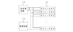
上記ヒストグラム処理回路70の構成は図5に示され、並列接続された#1〜#nのn個の自己加算型階調・度数モジュール71、各階調・度数モジュール71の動作を制御する制御回路72、有効データの度数を予め算出する前処理回路73から構成される。尚、上記階調・度数モジュール71は、入力画像におけるサンプル数と階調数とのうちの大きい方の数に見合うだけの数が使用される。
【0033】
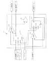
それぞれの階調・度数モジュール71は、図6に示すように、階調ラッチ74、比較器による一致検出回路75、OR回路76、度数ラッチ77、加算器78によって構成されている。上記階調ラッチ74のD入力端子、CK端子、E端子、SET端子には、それぞれ、上記ヒストグラム用距離データメモリ41からの距離データ(階調データ)、同期クロック、上記制御回路72からのロード信号(ラッチイネーブル信号)、初期化を行うクリア信号が入力され、上記一致検出回路75の各入力端子に、上記ヒストグラム用距離データメモリ41からの階調データと上記階調ラッチ74のQ端子からのラッチデータとが入力される。
【0034】
また、上記度数ラッチ77のD入力端子には、上記前処理回路73からの度数データと上記度数ラッチ77のQ端子からのラッチデータとを上記加算器78によって加算した値が入力され、上記度数ラッチ77のCK端子、E端子、CL端子には、それぞれ、同期クロック、上記OR回路76の出力、上記制御回路72からのクリア信号が入力される。上記OR回路76には、上記一致検出回路75からの一致判定信号が入力されるとともに、上記制御回路72からのロード信号が入力される。そして、上記一致検出回路75の一致判定信号が上記制御回路72に入力され、上記階調ラッチ74のQ端子から階調データが出力されるとともに上記度数ラッチ77のQ端子から度数データが出力され、上記ヒストグラムメモリ62にストアされる。
【0035】
また、上記FPGA61内部に構成されるオプティカルフロー処理回路80は、メイン画像のNo1ブロックと次フレームのメイン画像のNo2ブロックの探索エリアから、それぞれ1画素毎の輝度データを読み込み、所定のバイト数のデータ系列に並び替えて次段に転送するデータ転送バッファ81、このデータ転送バッファ81から転送された2系統のデータ系列に対してシティブロック距離を計算し、このシティブロック距離が最小値となる位置をNo2ブロックの探索結果として出力する演算処理回路85等から構成される。
【0036】
上記データ転送バッファ81は、図7に示すように、シティブロック距離を計算する際の基準画像であるメイン画像と比較画像であるサブ画像とに対応する基準側バッファ81aと比較側バッファ81bとからなり、1バイトずつデータを読み込んで6バイトのデータ系列に並び替え、次段の演算処理回路85に転送する。
【0037】
上記基準側バッファ81aは、図7(a)に示すように、1バイトバッファに6バイトバッファが接続された入力段82と、12セットの6バイトバッファをリング状に接続したリングバッファ83とから構成され、このリングバッファ83先頭の出力バッファ83aからデータを上記演算処理回路85にリング状に転送する。また、上記比較側バッファ81bは、図7(b)に示すように、同様に1バイトバッファに6バイトバッファが接続された入力段82と、11セットの6バイトバッファをリング状に接続したリングバッファ84とから構成され、リングが一周したら最初のデータは破棄し、次のデータ系列を読み込んで、同様に、先頭の出力バッファ84aからデータを上記演算処理回路85にリング状に転送する。
【0038】
すなわち、バッファセットをリング状に構成することにより、バッファセットから演算処理回路85に転送するリソースを1/12にすることが可能となり、6×12のデータセレクタを不要とすることができる。
【0039】
上記演算処理回路85は、12画素×6画素=72画素のシティブロック距離を計算する必要があるため、図8に示すように、6個の絶対値演算器86と6個の加算器87とをピラミッド状に接続したパイプライン構造のシティブロック距離計算回路85aに、上記絶対値演算器86と同様の演算器にラッチを組み合わせた最小値検出回路85bを接続した構成となっている。
【0040】
シティブロック距離計算回路85aでは、パイプライン構造の1段目が6個の絶対値演算器86からなる絶対値計算ブロック、2段〜4段目が、それぞれ、3個の加算器87からなる第1加算ブロック、1個の加算器87からなる第2加算ブロック、1個の加算器87からなる第3加算ブロック、5段目(最終段)が1個の加算器87からなる総和加算器となっており、6画素分を同時に入力して並列計算を行った後に連続計算を行うパラレル・シリアル型計算回路により処理速度と回路規模の両立を図っている。
【0041】
次に、上記航法処理部90は、ヒストグラム処理結果によるNo1ブロックの決定やオプティカルフローエリアの選定(No2ブロックのスキャン開始位置の設定)等を行う画像処理プロセッサ系SYS1と、オプティカルフロー処理結果に基づくフレーム間移動量、機体の回転・並進成分の演算、航法軌跡の算出等を行う航法処理プロセッサ系SYS2とに大別される。
【0042】
上記画像処理プロセッサ系SYS1には、上記データ転送バッファ81への基準側画像データとしてNo1ブロックのメイン画像データをストアするNo1ブロックメイン画像データメモリ91が備えられ、航法処理プロセッサ系SYS2には、上記演算処理回路85の演算結果をストアするオプティカルフローデータメモリ92が備えられている。
【0043】
以上の構成による自己位置認識システムでは、電源投入によるシステム起動時、ハードウエア各部が初期化されるとともに、ステレオカメラの仕様定数値、航法処理変数値等の変数値が初期化される。同時に、シェーディングコントローラ50によってシェーディング補正用メモリ33のシェーディング補正データがROMからRAMに転送される。
【0044】
次に、システムクロックに基づく水平同期信号及び垂直同期信号が各カメラ12a,12b,13a,13bに外部同期信号として供給され、上記航法処理部90によって書き込まれているシャッタースピード値でFPGA35のカメラコントローラ51からカメラアセンブリ10の各カメラに別々にシャッタートリガ信号が出力される。
【0045】
そして、ステレオ処理部30において、ステレオカメラ12a,12bで撮像された遠方画像、ステレオカメラ13a,13bで撮像された下方画像に対し、それぞれ、2台のカメラのバラツキの補正や感度バラツキの補正がなされた後、画像メモリ36にストアされるとともに、ステレオマッチングにより距離画像が生成され、この距離画像からオプティカルフローに使用可能な小領域(No1ブロック)を評価するためのヒストグラムがオプティカルフロー処理部60のヒストグラム処理回路70で作成される。
【0046】
遠方画像、下方画像にそれぞれについてヒストグラムが作成されると、航法処理部90では、作成されたヒストグラムを参照して遠方メイン画像、下方メイン画像のそれぞれについてNo1ブロックを決定し、また、No2ブロックの探索開始アドレスを決定する。このNo1ブロックの先頭アドレス、No2ブロックの探索開始アドレスは、オプティカルフロー処理部60のオプティカルフローアドレスメモリ63に書き込まれる。
【0047】
オプティカルフロー処理部60では、オプティカルフロー処理回路80によって、No2ブロックの探索開始アドレスからスタートして、順次、対応する領域のNo1ブロックとのシティブロック距離を計算し、シティブロック距離が最小値を取る領域をNo2ブロックとして、その領域のアドレスを出力する。
【0048】
これにより、航法処理部90では、下方画像のNo1ブロックとNo2ブロックとの間の移動量から移動体(ヘリコプター)の速度成分(回転と並進とを含む速度成分)を演算し、この速度成分から下方画像のNo1ブロックとNo2ブロックとの間の移動量から算出される回転速度成分を差し引いて純並進速度成分を求める。そして、この純並進速度成分を累積して航法軌跡を計算する。
【0049】
以上の処理のタイミングは、自己位置認識システムの内部カウンタであるラインNoで全て管理されており、このラインNoは、画像サンプルの終了時にリセットされる。本形態では、システムクロックにより駆動されて00Hからカウントアップされ、82Hから9CHまでの区間で次フレームの画像がサンプルされ、その終了時(9CH)にリセットされる。
【0050】
次に、撮像画像をサンプルした後の各部の動作を詳細に説明する。まず、アナログI/F31では、D/Aコンバータ34からのコントロール電圧に応じてGCA31aで画像信号のゲインを調整し、各ステレオカメラ12,13毎の2台のカメラのゲインのバラツキを調整してA/Dコンバータ32に出力する。A/Dコンバータ32では、D/Aコントローラ45からのリファレンス電圧によって各ステレオカメラ12,13毎に2台のカメラの画像信号のオフセット差を調整し、アナログ画像を所定の輝度階調(例えば256階調のグレースケール)のデジタル画像に変換する。尚、上記GCA31aのゲインコントロール電圧、A/Dコンバータ32のリファレンス電圧は、航法処理部90によってFPGA35内部に書き込まれている電圧値がD/Aコントローラ45に転送される。
【0051】
上記アナログI/F31からA/Dコンバータ32を経て各ステレオカメラ12,13毎にゲイン・オフセットの整合が取られたデジタル画像データは、FPGA35内部のLUT46へアドレスデータとして与えられ、LUT46からのデータとシェーディングコントローラ50からの指示で転送されるシェーディング補正用メモリ33からのシェーディング補正データとが乗算器47で乗算される。これにより、各ステレオカメラ12,13毎に更に厳密にゲイン及びオフセットが整合されるとともに、各ステレオカメラ12,13の光学系に発生するシェーディング現象による輝度低下が補正される。
【0052】
次に、乗算器47から出力される画像データがログ変換テーブル48によって対数変換されて明るさに比例するノイズ成分の影響が除去され、画像メモリ36に遠方メイン画像、遠方サブ画像、下方メイン画像、下方サブ画像のデータが、次段のステレオマッチング回路39での処理に適応した形態でストアされる。この画像メモリ36にストアされる画像データは、水平ラインの4ライン毎のデータであり、同時に、水平4ラインに1ライン分の画像データがシャッター制御用元画像メモリ37にストアされるとともに、オプティカルフロー用メモリ38に遠方・下方のメイン画像データが全ラインストアされる。
【0053】
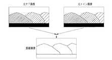
その後、画像メモリ36の元画像データがステレオマッチング回路39に4バイトずつ転送され、4×4画素の領域についてメイン画像とサブ画像とのステレオマッチングが100画素ずれまで行われ、図9に示すような距離画像が生成されて距離画像メモリ40及びヒストグラム用距離データメモリ41に書き込まれる。尚、ステレオカメラの撮像画像から距離画像を生成する処理については、本出願人による特開平5−114099号公報に詳述されている。
【0054】
以上のステレオ処理により距離画像を取得すると、オプティカルフロー処理部60では、図10に示すように、No1ブロックを元画像から抽出するための12×6画素の領域の距離データのヒストグラムをヒストグラム処理回路70で作成する。このヒストグラム作成処理は、400×200画素の距離画像に対して縦4画素・横4画素ずつずらして行われ、水平1ラインについて98個、全体で横98×縦49個の領域について行われる。
【0055】
詳細には、ヒストグラム処理回路70では、まず、クリア信号により、データをラッチする階調・度数モジュール71の番号を指定するための制御回路72内のモジュール番号カウンタが0に初期化され、また、全ての階調・度数モジュール71内の度数ラッチ77が0にされるとともに、階調ラッチ74が設定値(入力階調データの最大値が64Hの場合、FFH)に初期化される。また、最初の4×4画素の領域のデータの度数が前処理回路73でカウントされる。
【0056】
そして、初期化後、最初の4×4画素の小領域の代表階調データ(距離データ)が入力されると、制御回路72内部のモジュール番号カウンタが1とされ、#1の階調・度数モジュール71#1(以下、モジュール番号を添え字#1〜#nによって示す)内の階調ラッチ74#1にロード信号が出力されるとともにOR回路76#1を介して度数ラッチ77#1にロード信号が出力される。これにより、階調ラッチ74#1がイネーブルとなって同期クロックにより最初の階調データが書き込まれてラッチされ、また、度数ラッチ77#1がイネーブルとなって同期クロックにより前処理後の度数データが度数ラッチ77に書き込まれる。
【0057】
次に、2番目の小領域の階調データが階調・度数モジュール71#1に入力されると、階調・度数モジュール71#1では、内部の階調ラッチ74#1でラッチした最初の小領域の階調データと2番目の小領域の階調データとを一致検出回路75#1で比較し、一致判定信号をOR回路76#1及び制御回路72に出力する。
【0058】
この一致判定信号は、データが一致しているときに1、不一致のときに0の信号であり、一致検出回路75#1の出力が1のとき、すなわち、最初の小領域の階調データと2番目の小領域の階調データとが一致するとき、OR回路76#1を介して度数ラッチ77#1がイネーブルとなり、この度数ラッチ77#1でラッチしている度数データと今回入力された度数データとが加算器78で加算されて度数ラッチ77#1に書き込まれる。
【0059】
一方、一致検出回路75#1の出力が0のとき、すなわち、ラッチしている最初の小領域の階調データと今回入力された2番目の小領域の階調データとが一致しないときには、OR回路76#1を介して度数ラッチ77#1がディスエイブルの状態のままラッチデータが保持される一方、制御回路72では内部のモジュール番号カウンタを2とし、#2の階調・度数モジュール71#2にロード信号を出力する。これにより、#2の階調・度数モジュール71#2内部の階調ラッチ74#2及び度数ラッチ77#2がイネーブルとなり、階調ラッチ74#2に2番目の小領域の階調データが書き込まれるとともに、度数ラッチ77#1に2番目の小領域の度数データが書き込まれる。
【0060】
以上の動作を繰り返し、1つの12×6の領域に対する処理が終了すると、#1の階調・度数モジュール71#1から順に階調及び度数データを読み出してヒストグラムメモリ62にストアしてゆき、度数が0のモジュールで動作を停止してクリア信号による再初期化を行い、次の12×6の領域の処理に移る。
【0061】
すなわち、図11のタイムチャートに示すように、階調データと前処理で計算した度数データとを各モジュールの入力データとして各モジュールでラッチしておき、入力された階調データが過去にラッチした階調データと一致する場合、そのモジュールでラッチしている度数データに新たな度数データを加算して再ラッチすることで度数データを蓄積する。
【0062】
一方、過去に階調データがラッチされたどのモジュールでもデータが一致しない場合には、制御回路72内部のモジュール番号カウンタがカウントアップされて新しいモジュールにロード信号が出力され、新しい階調データ及び度数データが新しいモジュールにラッチされる過程を繰り返し、入力画像の全ての種類の階調データ及び前処理後の度数データが次々とラッチされ、度数データが蓄積されてゆく。
【0063】
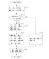
以上のヒストグラム処理回路70で作成されたヒストグラムは、航法処理部90の画像処理プロセッサ系SYS1で参照され、遠方メイン画像、下方メイン画像のそれぞれについてNo1ブロックが決定される。このNo1ブロックの決定は、図13に示すNo1ブロック群取得処理ルーチンに従って行われる。
【0064】
このルーチンでは、まず、ステップS30で、取り込んだ撮像画像に対し、遠方処理をすべきか下方処理をすべきかを選択する。この処理の選択は、撮像画像の処理タイミングが遠方画像が先で下方画像が次であることから、先に取り込んだ画像は遠方画像であるとしてステップS31以降の遠方処理へ進み、次に取り込む画像に対してはステップS33以降の下方処理へ進む。
【0065】
ステップS31以降の遠方処理では、ステップS31で、遠方画像に対してNo1ブロックを探す走査範囲をイニシャル処理として設定する。この走査範囲は、例えば、撮像面の水平走査方向をW、垂直走査方向をTとする全領域W×Tの内、水平走査方向の画面両端の検索しろi2と、垂直走査方向の画面両端の検索しろj2とを除いた領域WA×TSL(WA=W−2・i2、TSL=T−2・j2)とし、水平走査方向の幅WAを均等に10分割して10個の探索エリアWS×TSLを設定する。すなわち、各探索エリアWS×TSL毎に最大1個のNo1ブロックを抽出するようにし、同じ探索エリアから2個以上のNo1ブロックを抽出することなく、撮像画面の特定の領域に抽出箇所が集中しないようにする。
【0066】
次に、ステップS32で、探索エリアWS×TSLの中から12×6ピクセルの絵柄箇所を切り出し、切り出し箇所の画像品質を評価し、No1ブロックを決定する。12×6ピクセルの絵柄箇所の画像品質は、対応する距離画像の12×6ピクセルの領域のヒストグラムによって良否を判定する。
【0067】
すなわち、12×6ピクセルの距離画像領域の距離情報にバラツキがあると、これから定めようとするNo1ブロックは、ある1箇所(1点)を見ているのではなく、同じ窓(小領域)の中に遠近が異なる複数箇所の対象物を見ていることになり、ヒストグラム中に遠近が異なる複数の対象物がノイズとして出現することになる。従って、ヒストグラム中から最も出現頻度が多い距離画像値maxzと、その最大ヒストグラム値maxnumを求め、この最大ヒストグラム値maxnum近辺の他の距離画像値の出現頻度を調べることにより、使用する領域の対象物の候補を定めることができる。
【0068】
本形態では、maxz±2の範囲に絞って12×6ピクセルの距離画像領域に含まれる距離画像値と、それぞれのヒストグラム値を調査するようにしており、maxz±2の範囲の出現頻度の総度数dsumを以下の(1)式で算出し、所定の閾値に定める許容範囲内にある「OK情報」の度数が所定の数を満足し、且つ、maxz±2の範囲の総度数dsumが「OK情報」の度数の内の大部分を占める(例えば、80%以上)とき、切り出した12×6ピクセルの絵柄箇所は信頼性のある画像と判断し、No1ブロックとして決定する。
dsum=m2+m1+maxnum+p1+p2 …(1)
但し、m2:maxz−2における出現頻度
m1:maxz−1における出現頻度
p1:maxz+1における出現頻度
p2:maxz+2における出現頻度
【0069】
次に、No1ブロックの絵柄抽出が決定すると、航法計算に必要な対象物までの距離値を正確に知るため、12×6ピクセルの距離画像領域の平均距離画像値fz1を以下の(2)式によって求める。
以上の遠方画像に対するNo1ブロック取得処理を、各探索エリアWS×TSL毎に行い、画像全体で最大10個のNo1ブロックを取得すると、ステップS33以降の下方処理に移行する。尚、探索エリアWS×TSLで適正なNo1ブロックが見つからないときには、該当する探索エリアでの抽出を中止する。
【0071】
下方処理では、ステップS33において、下方画像に対するイニシャル処理として、No1ブロックを探す走査範囲を設定する。この下方画像の走査範囲は、遠方画像の10個の探索エリアWS×TSLに対し、垂直走査方向をTAとした領域WS×TAで、画面の中央ラインThから進行方向側に所定量オフセットさせたラインTtを探索開始ラインとする領域であり、画面全体に分散した特徴的な絵柄を抽出できるよう、垂直走査方向の幅TAを3分割して30個の探索エリアWS×TSGを設定する。
【0072】
この場合、上記オフセットラインTtは、前回処理で求めた並進速度によって可変するようにしており、下方画像の動きを考慮し、前・後進速度に応じて撮像面を有効に利用するようにしている。
【0073】
次に、ステップS34では、探索エリアWS×TSGの中から12×6ピクセルの絵柄箇所を切り出し、切り出し箇所の画像品質を評価してNo1ブロックを決定する。この下方画像におけるNo1ブロックの決定は、前述した遠方画像におけるNo1ブロックの決定と同様であるが、「OK情報」を選別するための閾値が異なる。すなわち、下方画像の動きから並進速度成分を計算するため、距離画像データが多く存在する領域で、且つ、バラツキが小さい平面的な領域をNo1ブロックの候補として閾値を定める。
【0074】
そして、上記ステップS34において、水平走査方向に最大10個のNo1ブロックを取得すると、ステップS35へ進んで下方画像における全ての探索エリアの処理が済んだか否かを調べ、全ての処理が終了していない場合には、ステップS34へ戻って、一段下の探索エリアに対する処理を続行する。そして、このステップS34→ステップS35→ステップS34のループを3回繰り返して30個の探索エリアについての処理を行う。この場合においても、探索エリアWS×TSGで適正なNo1ブロックが見つからないときには、該当する探索エリアでの抽出を中止する。
【0075】
以上により、遠方画像・下方画像のそれぞれについてNo1ブロック群を取得すると、画像処理プロセッサ系SYS1では、さらに、No1ブロックと同じ絵柄を持つNo2ブロックを探すための探索開始エリアを、所定時間経過後のNo1ブロックの所在を予測して設定する。
【0076】
すなわち、No1ブロックが決定すると、No1ブロックの撮像面での代表座標が決まるため、まず、No1ブロックの代表座標を中心として、上下左右に所定のオフセット量(xf,yf)を与えた4点a,b,c,dを決定する。そして、この4点a,b,c,dを結んだ4角形の枠内すなわち(2・xf)×(2・yf)の領域を、画面に動きが無いときの撮像情報でNo1ブロックと同じ絵柄が存在すると予測した探索エリアとし、この探索エリアを、遠方・下方画像のそれぞれの特徴を考慮して配置する。
【0077】
遠方画像の場合には、測定点から十分遠く(例えば、30m以上)離れた箇所を測距するため、短時間での上下・左右の並進移動による画像の変化を受け難く、遠方画像で得たNo1ブロックの動きは、回転成分による動きとして捉えられる。従って、遠方画像では、撮像面座標の原点Oの回りの回転角αによって探索エリアの4点a,b,c,dの座標値を変換し、4点a,b,c,dを結んだ4角形の探索エリアを設定する。
【0078】
一方、下方画像の場合には、撮像面上の移動量は、並進成分、回転成分のどちらの動きで生じたものか判断し難い。このため、一定時間経過後のNo1ブロックの所在を予測し、その移動先に、次フレーム以降のNo2ブロックの検索エリアを設定する。すなわち、ヘリコプターの動きに対して処理速度が十分に速いときや、実撮像範囲が広いときには、画面毎の画像の動きは大きくないため、探索エリアは単位時間当たりの最大変化量を探索範囲と置けば良いが、ヘリコプターが大きく動く場合には、処理速度や撮像範囲が十分でないと仮定して動きを予測し、過去の速度成分を参考にして探索エリアを設定する。
【0079】
一定時間経過後のNo1ブロックの所在を予測するには、前回の角速度計算で得られたロール・ピッチ・ヨー成分と前回の並進速度計算で得られた純並進量とから、所定時間後のNo1ブロックの移動先を撮像面座標の動き(仮想的なオプティカルフロー)に変換する。そして、No1ブロックを決定したフレームとNo2ブロックを探し出す対象フレームとの間の仮想的なオプティカルフローに基づいて、No2ブロックの探索エリアを設定する。
【0080】
以上により決定されたNo1ブロックの画像データは、画像処理プロセッサ系SYS1のNo1ブロックメイン画像データメモリ91にストアされ、No1ブロックのアドレスとNo2ブロックの探索開始アドレスとがオプティカルフロー処理部60のオプティカルフローアドレスメモリ63にストアされる。
【0081】
オプティカルフロー処理部60では、No1ブロックメイン画像データメモリ91からのデータと次のフレームでサンプルされてオプティカルフローメモリ38にストアされているデータとをオプティカルフロー処理回路80のデータ転送バッファ81に読み込み、演算処理回路85でシティブロック距離を計算してNo2ブロックを探索する。
【0082】
すなわち、図12に示すように、時刻t=t1における画像で決定したNo1ブロックの12×6画素のデータをai,j(i=0〜11,j=0〜5)、時刻t=t1+Δtにおける画像のNo2ブロックの検索エリアの12×6画素のデータをbi,j(i=0〜11,j=0〜5)として、以下の(3)式に示すシティブロック距離Hが最小値を取る位置がNo2ブロックの位置すなわちNo1ブロックの移動後の位置となる。尚、(3)式中、最初のΣはj=0〜5の総和、次のΣはi=0〜11の総和を示す。
H=ΣΣ│ai,j−bi,j│ …(3)
【0083】
このシティブロック距離を演算するため、データ転送バッファ81では、基準側バッファ81aにNo1ブロックメイン画像データメモリ91から1バイトずつ画像データを読み込むとともに、比較側バッファ81bにオプティカルフローメモリ38から1バイトずつ画像データを読み込み、6バイトのバッファセットが揃ったとき、それぞれ、リングバッファ83,84に転送する。
【0084】
各リングバッファ83,84では、1番目のバッファセットが演算処理回路85に転送され、同時に、次段のバッファにも転送される。この動作を12回繰り返して演算処理回路85にデータを転送すると、1つのシティブロック距離が演算される。
【0085】
リングが1周して次のシティブロック距離演算に入ると、基準側バッファ81aでは、12セットのリングバッファ83の先頭バッファである出力バッファ83aに1番目のデータが格納され、比較側バッファ81bでは、11セットのリングバッファ84の先頭バッファである出力バッファに2番目のデータが格納される(1番目のデータは破棄されている)。今度は、リングを回転させるだけで、比較側の2番目から12番目のデータが演算処理回路85に送られ、最後にリングを回している間に読み込んだ13番目のデータを演算処理回路85に転送することができる。
【0086】
演算処理回路85では、12×6=72画素のシティブロック距離を演算するため、シティブロック距離計算回路85aの1段目の6個の絶対値演算器86に6画素分のデータを入力し、輝度差の絶対値を計算する。すなわち、基準画像側の画素の輝度から比較画像側の画素の輝度を引き算し、結果が負になった場合、2の補数から絶対値の計算を行なう。
【0087】
次に、初段を通過すると、2段目では、3個の加算器87の各々で、1段目の絶対値演算器86からの2つの同時入力データを加算する。このとき、同時に1段目の6個の絶対値演算器86では、次の6画素分の絶対値計算を行う。同様に、3段目、4段目で前段の出力を加算し、5段目では、4段目の出力値と自身の出力値とを加算して総和を取る。そして、5段目で12加算が終了すると、6×12=72画素分のシティブロック距離の演算値が出力される。
【0088】
以上の動作をNo2ブロックの探索開始アドレスを1つずつインクリメントしてシティブロック距離を演算し、シティブロック距離の演算値と、このシティブロック距離の演算値が最小値を取ったときのアドレスを航法処理プロセッサ系SYS2のオプティカルフローデータメモリ92に出力する。そして、1つの領域についての処理を終了すると、オプティカルフローアドレスメモリ63から次回のNo1ブロックのアドレスを参照し、オプティカルフローメモリ38からNo1ブロックメイン画像データメモリ91に次回のNo1ブロックの画像データを転送する。
【0089】
次に、航法処理プロセッサ系SYS2において、オプティカルフロー処理結果を用いて回転・並進速度が演算され、この演算結果に基づく航法軌跡から自己位置が認識される。すなわち、航法処理プロセッサ系SYS2では、遠方メイン画像のオプティカルフローに基づいて実距離成分の差を求め、この実距離成分の差から回転速度成分(ロール・ピッチ・ヨーの角速度)を算出するとともに、下方メイン画像のオプティカルフローに基づいて実距離成分の差を求め、この実距離成分の差による速度成分から回転速度成分を除いて3次元方向(X,Y,Z方向)の純並進速度を求める。そして、この並進速度を原点から見た3次元方向の速度に変換し、イニシャル地点から速度成分を累積して原点からの移動量や現在位置を割り出す。
【0090】
遠方画像の動きから回転速度成分を演算する処理は、図14の回転演算処理ルーチンによって行われる。このルーチンでは、まず、ステップS51で、No1ブロック群の配列パターンとオプティカルフロー処理部60によって探索されたNo2ブロック群の配列パターンとを比較し、オプティカルフローの信頼性を評価する。
【0091】
すなわち、遠方画像の性質から、回転速度成分によるNo1ブロック→No2ブロックの理想的な画像の動きでは、各ブロックの相対位置関係(配列パターン)は殆ど変わらない。従って、No1ブロック群の配列パターンとNo2ブロック群の配列パターンとを比較し、各ブロックの配置が明らかに異なる場合には、該当するブロックをNo1・No2ブロック群について共に排除する。
【0092】
この配列パターンの評価は、No1ブロック群における各ブロック間の距離及び各ブロックで構成する三角形の面積を、No2ブロック群における値と比較することで行う。例えば、一つのブロックAについて着目すると、ブロックAがNo2ブロック群において正しい位置に選択されたか否かを評価するには、まず、No1ブロック群におけるブロックAと他のブロックBとの距離(A1−B1)を、No2ブロック群におけるブロックAとブロックBとの距離(A2−B2)と比較し、同様に、ブロックA−ブロックC、ブロックA−ブロックDについても距離を比較する。
【0093】
そして、3つともNo1ブロック群とNo2ブロック群とにおける距離が等しければ距離のチェックはOKとし、そうでなければ、次のブロックE,G,…と順次比較するブロックを変えてゆき、先に3個OKになれば距離のチェックはOK、先に3個NGになれば距離のチェックはNGとする。
【0094】
このように、ブロックAの3点(B,C,D)に対する距離のチェックがOKになった場合、次に、ブロックA、B,Cの各代表座標で構成される三角形の面積ABCをNo1ブロック群とNo2ブロック群とについて求め、大きさを比較する。この比較を三角形ACDについても行い、どちらもNo1ブロック群とNo2ブロック群とで同じ面積であれば、最終的に、ブロックAの位置はNo2ブロック群において正しく選択されたと判定する。
【0095】
この際、距離のチェックは、ピタゴラスの定理による二乗値のまま比較し、また、三角形の面積のチェックは、ベクトルの外積を計算して三角形の面積の2倍の値(平行四辺形の面積)で比較することにより、計算効率を高める。
【0096】
以上の配列パターンの評価により適正でないブロックを排除した後、ステップS52へ進み、適正でないブロックを排除した後のNo2ブロック数が所定の数か否かを調べる。そして、計算精度を維持するのに必要な所定の数に達していないときには、上記ステップS52からステップS55へ分岐して前回の角速度成分の計算結果を今回処理の値としてメモリを更新した後、ステップS56へ進み、所定の数のNo2ブロックを確保できたときには、上記ステップS52からステップS53へ進む。
【0097】
ステップS53では、No2ブロックの撮像面座標を、カメラ固定のX,Y,Z直交座標である実空間座標に直す。レンズの焦点距離f、メインカメラ軸Zmとサブカメラ軸Zsとの基線長LS(Ss)、ステレオ画像のズレ量Xrとすると、測距対象点Mまでの距離Zは、三角測量によって以下の(4)式で与えられるため、この関係に基づいて撮像面座標を実空間座標に変換する。
【0098】
Z=LS(SS)・f/Xr …(4)
続くステップS54では、非線形型最小二乗法によってNo1ブロック群とNo2ブロック群との間の位置の差分に相当する角速度(ロール・ピッチ・ヨー)を求める。すなわち、前回の回転・並進の速度成分を初期値として撮像素子上の動きに換算してNo1ブロックとNo2ブロックとの位置の差を求め、さらに、線形近似を行って3軸(X,Y,Z軸)の回転成分毎に偏微分し、適当な偏角を与えてロール・ピッチ・ヨー毎に撮像素子上のNo1ブロックとの位置の差の変化量(dx,dy)を求める。ロール・ピッチ・ヨーの各成分は、この変化量(dx,dy)の極限として与えられる。
【0099】
従って、上記変化量(dx,dy)を求める処理をNo1・No2ブロック全てについて行い、最小二乗法で回転成分を求める。この最小二乗法では、3元1次方程式を解くことになるが、係数行列についての転置行列が等しく、対角要素が他の要素に比べて十分に大きい値であるため(正定値対称)、コレスキー法による数値計算を適用することができ、No1ブロックに対してのロール・ピッチ・ヨーの各々の値を求めることができる。
【0100】
実際には、上記手法による解は、非線形のため真値にはならない。従って、得られた値を初期値にして再び最小二乗法を繰り返す非線形型最小二乗法によって真値に近づけるわけであるが、真値を求める際には、上記変化量(dx,dy)の収束具合(理想的には0)を監視して決定すべき処置が必要である。すなわち、限定した範囲の角速度成分を適度な精度で得る場合には、繰り返し計算回数を所定の回数(例えば、5回)で打ち切り、処理に要する時間を短縮することができる。
【0101】
上記ステップS54の処理によってカメラ固定のXYZ直交座標系における角速度成分を求めると、次に、ステップS56へ進み、ロール成分rl、ピッチ成分pt、及び、ヨー成分ywを、回転行列Rotの要素に展開してルーチンを抜ける。この回転行列Rotは、ロール、ピッチ、ヨーの各軸毎の回転行列の積であり、例えば、以下の(5)〜(13)式で示すように、3×3の正方行列の要素として展開できる。
Rot[0][0]=(cy・cr)−(sy・ans) …(5)
Rot[1][0]=−(cp・sr) …(6)
Rot[2][0]=(sy・cr)+(cy・ans) …(7)
Rot[0][1]=(cy・sr)+(sy・ans') …(8)
Rot[1][1]=(cp・cr) …(9)
Rot[2][1]=(sy・sr)−(cy・ans') …(10)
Rot[0][2]=−(sy・cp) …(11)
Rot[1][2]=sp …(12)
Rot[2][2]=(cy・cp) …(13)
但し、cy=cos(yw) cr=cos(rl)
cp=cos(pt) sy=sin(yw)
sr=sin(rl) sp=sin(pt)
ans=sp・sr ans'=sp・cr
【0102】
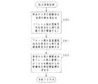
次に、回転速度成分と並進速度成分とを含む下方画像の動きから純並進速度成分を求める処理について説明する。この処理は、図15の並進演算処理ルーチンによって行われ、まず、ステップS60で、計算精度を維持するに必要な所定のサンプル数だけNo2ブロック群を取得できたか否かを調べ、所定のサンプル数を取得できたときには、ステップS60からステップS61へ進み、所定のサンプル数を取得できないとき、ステップS60からステップS71へ進んで前回の並進速度成分の計算結果を今回処理の値としてメモリを更新し、ルーチンを抜ける。
【0103】
ステップS61では、No2ブロックの平均距離画像値を評価する。この評価は、No1ブロックとNo2ブロックとで距離画像値が閾値以上に異なっているブロックを排除するためのものであり、該当するブロックがあるときには、そのブロックを除いてNo2ブロック群全てを評価したか否かを調べるステップS67へジャンプし、このステップS67からステップS61へ戻るループによってNo1ブロック群及びNo2ブロック群全体から距離画像値が閾値以上に異なっているブロックを排除する。
【0104】
その後、上記ステップS61によるNo2ブロックの平均距離画像値の評価を経てステップS62へ進み、No1・No2ブロック群の個々のサンプルを、レンズ歪み分を補正した撮像面座標値に修正し、測距精度のバラツキが少ない新たなNo1・No2ブロック群に更新する。尚、ステップS61→ステップS67→ステップS61のループで排除したブロック数が多く、計算精度を維持するに必要なサンプル数を確保できないときには、前回の並進速度成分の計算結果を今回処理の値として並進演算処理を終了する。
【0105】
続くステップS63では、No1・No2ブロックの撮像面座標値と、それぞれの距離画像値とから実空間の座標(カメラ固定のXYZ直交座標)値を求め、ステップS64で、No2ブロックから求めた実空間座標値を、最新の回転行列で回転成分を差し引いた純並進成分の実空間座標値に変換し、ステップS65へ進んで、画像の動き(移動ベクトル)を実空間座標値の差分で求める。
【0106】
すなわち、遠方画像の撮像面と下方画像の撮像面とは互いに直交関係にあることから、回転移動と並進移動とを含んだNo1・No2ブロック間の移動ベクトル量に、先に求めた回転行列Rot(No2→No1ブロックへの回転行列)を掛け合わせることにより(相対的に回転させることにより)、回転成分の動きを実距離のクラスで除去することができる。
【0107】
次いで、ステップS66へ進み、実空間移動量を新たに記録して測距したブロック数を勘定すると、ステップS67で、No2ブロック群の全てを評価したか否かを調べる。そして、全部の評価が終わっていないときには、ステップS61へ戻り、全部の評価が終わったとき、ステップS68へ進み、区間推定等の統計処理によってオプティカルフロー全体に対して方向や大きさが異常である移動ベクトル(特異ベクトル)を排除するフィルタ処理を行い、特異ベクトルを排除した後の平均移動量を算出する。
【0108】
その後、ステップS69で、特異ベクトルの除去結果を調べ、特異ベクトルの数が多く、航法計算の精度を維持するのに必要なデータ数が確保できなくなったときには、前述のステップS71で前回の並進速度成分の計算結果を今回処理の値としてメモリを更新してルーチンを抜ける。一方、特異ベクトルが殆ど無いか、あるいは航法計算の精度を損なわない程度の数であるときには、上記ステップS69からステップS70へ進んで、成分(Xl,Yl,Zl)の3次元並進速度|S|を求め、この新しい並進速度でメモリ値を更新してルーチンを抜ける。
【0109】
以上の並進演算処理に続いて航法軌跡を求める図16の航法演算処理が実行される。この航法演算処理では、まず、ステップS80で原点(測距開始地点)から見た移動体の姿勢状態を求める。原点から見た移動体の姿勢状態は、測距開始地点で空間に固定したXYZ直交座標系から見た回転行列Rotsによって示される。このため、まず、測距開始地点で回転行列を単位行列化して初期化することで撮像面に直交する平面を実空間を表す基準面とし、この初期化時点の行列にフレーム間の回転行列(カメラ固定のXYZ直交座標系から見た回転行列)Rotを右から掛け込んだ行列を原点から見た移動体の姿勢を表す回転行列Rotsとする。
【0110】
すなわち、原点から見た姿勢を表す回転行列Rotsは、カメラ固定の座標系から見たフレーム毎の回転行列Rotを時系列的に積算した正方行列であり、以下の(14)式に示すように、前回までの原点から見た姿勢状態を表す回転行列Rotsに今回の回転演算処理で求めたフレーム間の回転行列Rotを右から積算した正方行列で今回処理における原点から見た姿勢を表す回転行列Rotsとして更新することにより、原点から見た移動体の最新の姿勢を表すことができる。
Rots=Rots・Rot …(14)
【0111】
尚、上記回転行列Rotsを用いることにより、以下の(15)〜(17)式によって原点から見た角度成分Roll(ロール),Picth(ピッチ),Yow(ヨー)を求めることができる。
Roll =atan(Rots[0][1]/Rots[0][0]) …(15)
Pitch=atan(Rots[1][2]/Rots[2][2]) …(16)
Yow =atan(Rots[2][0]/Rots[2][2]) …(17)
【0112】
次に、ステップS81へ進み、フレーム間の並進速度成分を原点から見た並進速度成分に変換すると、ステップS82で、原点から見た速度成分をフレーム毎に累積し、イニシャル地点からの移動体の実空間座標を求める。
【0113】
原点から見た並進速度Soは、原点から見た姿勢を表す回転行列Rotsとフレーム間の3次元並進速度Sとの積を、以下の(18)式に示すように、前回までの原点から見た並進速度Soに累積することで求めることができ、累積したベクトル量に所定の距離換算値を掛け合わせることで、航法軌跡を得ることができ、原点からの移動体の移動量を知ることができる。
So=So+(Rots)・S …(18)
【0114】
この場合、地上の適当な地点にランドマークを設置しておき、このランドマークをパターン認識等によって識別し、測距開始地点として原点をイニシャルすることで、上記航法軌跡から自己の相対位置を認識することができる。さらには、GPS等の衛星測位システムからの測位情報や既知の地図情報によって地上の適当な地点を原点としてイニシャルすることで、航法軌跡から自己の絶対位置を認識することができる。
【0115】
【発明の効果】
以上説明したように本発明によれば、高速なハードウエア回路によってリアルタイムでオプティカルフローを検出することができ、移動体に搭載可能な小型の装置で撮像画像からオンラインでオプティカルフローを検出して移動体の自己位置を認識することができる等優れた効果が得られる。
【図面の簡単な説明】
【図1】自己位置認識システムの全体構成図
【図2】カメラアセンブリの構成図
【図3】ステレオ処理部のブロック図
【図4】オプティカルフロー処理部のブロック図
【図5】ヒストグラム処理回路の構成図
【図6】自己加算型階調・度数モジュールの回路構成図
【図7】データ転送バッファの構成図
【図8】演算処理回路の構成図
【図9】ステレオ処理の説明図
【図10】ヒストグラム処理の説明図
【図11】自己加算型階調・度数モジュールのタイムチャート
【図12】オプティカルフロー処理の説明図
【図13】No1ブロック群取得処理ルーチンのフローチャート
【図14】回転演算処理ルーチンのフローチャート
【図15】並進演算処理ルーチンのフローチャート
【図16】航法演算処理ルーチンのフローチャート
【符号の説明】
10…カメラアセンブリ
20…自己位置認識装置
30…ステレオ処理部
39…ステレオマッチング回路
60…オプティカルフロー処理部
70…ヒストグラム処理回路
81…データ転送バッファ
85…演算処理回路
90…航法処理部
SYS1…画像処理プロセッサ系
SYS2…航法処理プロセッサ系[0001]
BACKGROUND OF THE INVENTION
The present invention relates to an optical flow detector for detecting an optical flow of an image with a hardware circuit at a high speed, and to detect the optical flow of the image at high speed by processing a captured image in real time to determine the self-position of a moving object. The present invention relates to a self-position recognition system for a mobile object to be recognized.
[0002]
[Prior art]
Conventionally, various technologies such as movement control, route detection, route detection, and location detection have been developed for autonomously moving mobile objects such as unmanned robots, autonomous traveling work vehicles, and unmanned helicopters. Position recognition is one of the important technologies.
[0003]
As a technique for self-position recognition, for example, in a moving body that autonomously travels on the ground, such as an autonomous traveling vehicle, a two-dimensional angular velocity is detected by a vibration gyroscope or an optical gyroscope, and translation is performed by a sensor that measures a ground velocity. There is a technology that detects the speed and calculates the amount of movement from the reference position to measure the self position. In the case of a flying mobile body such as an unmanned helicopter, the acceleration of the flying body is detected by detecting the gravitational acceleration with an inertial navigation device. There is a technique for detecting the amount of movement and knowing the amount of movement by integrating the acceleration.
[0004]
Furthermore, in recent years, a technique for recognizing the self-position of a moving body by applying image processing technology has been developed. In particular, two images with different imaging timings are picked up by picking up a camera on the moving body and picking up the surrounding environment. The technology for recognizing the self-position by detecting the movement of the moving object by obtaining the optical flow between the images enables analysis of the surrounding environment unique to images with a huge amount of information, and distinguishing complex terrain Accurate autonomous navigation can be realized.
[0005]
[Problems to be solved by the invention]
However, when detecting the movement of a moving object by optical flow of images, conventionally, processing capability equivalent to that of a workstation is required to capture a captured image and recognize its own position in real time. Invite.
[0006]
For this reason, with conventional devices that can be mounted on autonomous mobile bodies, it is necessary to deal with offline processing after capturing captured images, and it is necessary to recognize self-location in real time, such as unmanned helicopters Therefore, it is difficult to apply to a moving body, and the application range is extremely limited.
[0007]
The present invention has been made in view of the above circumstances, and an optical flow detection device for an image that can detect an optical flow at high speed in real time, and can be mounted on a moving body without increasing the size, and can capture a captured image in real time. It is an object of the present invention to provide a self-position recognition system for a moving body that can process and recognize the self-position of the moving body from an optical flow of an image.
[0008]
[Means for Solving the Problems]
According to the first aspect of the present invention, there is provided an optical flow detection device for an image in which one of two images picked up at different timings is used as a reference image and the other is used as a comparison image, and a corresponding position is searched for to obtain an optical flow between the images. BecauseAn image pickup unit having a stereo camera and a corresponding position in the two images picked up by the stereo camera are searched to obtain a pixel shift amount generated according to the distance to the target object, and the target object obtained from the pixel shift amount A distance image generation unit that generates a distance image in which the perspective information is digitized, and the gradation data and the frequency of the distance image are held in latches, respectively, and newly input gradation data and held gradation data By referring to the histogram data generated by the histogram generation unit by integrating the frequency of the stored gradation data by the coincidence output from the comparator for comparing the histogram data generated by the histogram generation unit, from among the reference images A plurality of characteristic pattern areas are extracted as the first block, and the area corresponding to the first block is extracted from the comparison image as the second block. An image processing unit for setting a search range for searching a, Of the reference image1st block Brightness data for each pixel and the comparison image2nd block The luminance data for each pixel is rearranged into a data sequence of a predetermined number of bytes, and a data transfer buffer for transferring each data sequence in a ring shape, and the absolute difference between the two systems of data transferred from the transfer buffer After calculating the value in parallel with multiple arithmetic units, the output of each arithmetic unit is added in series with multiple stages of adders to calculate the city block distance, and the address at which this city block distance is the minimum value is Of the reference image1st block And an arithmetic processing circuit for outputting as a corresponding position of the comparison image.
[0009]
According to a second aspect of the present invention, there is provided an imaging unit having a set of two stereo cameras that are mounted on a moving body and images a distant landscape, and a set of two stereo cameras that capture a lower landscape, and the stereo camera captures an image. A distance for generating a distance image obtained by searching for corresponding positions in the two images obtained to obtain a pixel shift amount corresponding to the distance to the target object and digitizing perspective information to the target object obtained from the pixel shift amount The image generation unit and the grayscale data and frequency of the distance image are respectively held in the latches, and are held by the coincidence output from the comparator that compares the newly input grayscale data with the held grayscale data. A histogram generation unit that integrates the frequency of gradation data to generate histogram data, and a histogram image generated by the histogram generation unit from the distance image A plurality of characteristic picture areas suitable for navigation calculation are extracted as a first block from among the areas, and an area corresponding to the first block is selected from images whose imaging timing is different from the image from which the first block is extracted. An image processing unit for setting a search range for searching as a second block, luminance data for each pixel of the first block, and luminance data for each pixel of the search range of the second block After the data transfer buffer that rearranges the data series into a number of data series and transfers each data series in a ring shape, and calculates the absolute value of the difference between the two systems of data transferred from the transfer buffer in parallel by a plurality of computing units The output of each arithmetic unit is added in series with a multi-stage adder to calculate the city block distance, and the address at which the city block distance is the minimum value is output. An optical flow processing unit having a processing circuit, and an optical flow from the first block to the second block based on an output from the optical flow processing unit for a captured image of a distant landscape and the distance image, and movement After calculating the rotational speed component between the body frames, the optical flow from the first block to the second block is obtained based on the output from the optical flow processing unit for the captured image of the lower landscape and the distance image. The velocity component between frames of the moving object is calculated, and the translational velocity component between the frames obtained by removing the rotational velocity component from the velocity component is converted into the translational velocity component viewed from the distance measurement start point, and the converted translational velocity is converted. Navigation processing that recognizes the position of a moving object by accumulating components and obtaining navigation trajectories in a three-dimensional space And a section.
[0010]
That is, in the optical flow detection device for an image according to the invention of
[0011]
In the self-position recognition system for a moving body according to the second aspect of the present invention, a distant landscape and a downward landscape are imaged by respective stereo cameras, and a distance image generation unit searches for corresponding positions in the two images by the stereo camera. Then, the pixel shift amount generated according to the distance to the object is obtained, and a distance image obtained by quantifying the perspective information to the target object obtained from the pixel shift amount is generated, and the histogram generation unit Gradation data and frequency are each held in a latch, and the frequency of the held gradation data is accumulated by a coincidence output from a comparator that compares the newly inputted gradation data with the retained gradation data. Generate histogram data.
[0012]
Then, the image processing unit extracts a plurality of characteristic picture areas suitable for navigation calculation from the captured image as a first block with reference to the histogram data of the distance image, and extracts the first block. A search range for searching a region corresponding to the first block as a second block from images having different imaging timings from the image is set.
[0013]
Next, in the optical flow processing unit, the luminance data for each pixel in the first block and the luminance data for each pixel in the search range of the second block are transferred to the captured image of the distant landscape and the captured image of the lower landscape. When data is rearranged into a data sequence of a predetermined number of bytes by the buffer and each data sequence is transferred to the arithmetic processing circuit in a ring shape, the arithmetic processing circuit parallels the absolute value of the difference between the two systems of luminance data with a plurality of arithmetic units. Then, the output of each arithmetic unit is added in series by a plurality of stages of adders to calculate the city block distance, and an address at which this city block distance becomes the minimum value is output.
[0014]
Then, the navigation processing unit obtains the optical flow based on the output from the optical flow processing unit for the captured image of the distant landscape and the distance image, calculates the rotational speed component between the frames of the moving object, and captures the lower landscape. The optical flow is calculated based on the output from the optical flow processing unit for the image and the distance image, the velocity component between frames of the moving object is calculated, and the translational velocity component between frames obtained by removing the rotational velocity component from this velocity component is obtained. When converted into the translational velocity component seen from the distance measurement start point, the converted translational velocity component is accumulated to obtain a navigation trajectory in the three-dimensional space, and the mobile object's own position is recognized.
[0015]
DETAILED DESCRIPTION OF THE INVENTION
Embodiments of the present invention will be described below with reference to the drawings. The drawings relate to an embodiment of the present invention, FIG. 1 is an overall configuration diagram of a self-position recognition system, FIG. 2 is a configuration diagram of a camera assembly, FIG. 3 is a block diagram of a stereo processing unit, and FIG. FIG. 5 is a configuration diagram of a histogram processing circuit, FIG. 6 is a circuit configuration diagram of a self-addition type gradation / frequency module, FIG. 7 is a configuration diagram of a data transfer buffer, and FIG. 8 is a configuration diagram of an arithmetic processing circuit, 9 is an explanatory diagram of stereo processing, FIG. 10 is an explanatory diagram of histogram processing, FIG. 11 is a time chart of a self-addition type gradation / frequency module, FIG. 12 is an explanatory diagram of optical flow processing, and FIG. 14 is a flowchart of the rotation calculation processing routine, FIG. 15 is a flowchart of the translation calculation processing routine, and FIG. 16 is a navigation calculation processing routine. Is a flow chart of emissions.
[0016]
FIG. 1 shows a
[0017]
The self-
[0018]
The
[0019]
The
[0020]
Similarly, the
[0021]
In the self-position recognition system of this embodiment, the movement of the moving object is detected from the optical flow, that is, the movement between images having different imaging times (timing) for each of the captured image of the distant landscape and the captured image of the lower landscape. The movement of the far image and the movement of the lower image are converted into the amount of movement in the real space based on the respective distance images, and the rotational speed component due to the movement of the far image is removed from the speed component due to the movement of the lower image. After obtaining the translational velocity component, it is converted into the translational velocity component seen from the distance measurement start point (starting point) and accumulated to obtain the navigation locus in the three-dimensional space to recognize the self position of the moving body.
[0022]
In this case, in order to detect the rotational speed of the moving body with the
[0023]
However, since it is practically difficult to make the reference points of the two main cameras 12a and 13a the same, the imaging plane vertical axis of the far-
[0024]
In this case, although the center of the three axes is placed on the
[0025]
The camera used for the
[0026]
The
[0027]
FIG. 3 shows a detailed configuration of the
[0028]
Various functions for digital signal processing configured in the
[0029]
On the other hand, as shown in FIG. 4, the optical
[0030]
The No1 block is determined by the
[0031]
The
[0032]
The configuration of the
[0033]
Each gradation /
[0034]
A value obtained by adding the frequency data from the
[0035]
Further, the optical
[0036]
As shown in FIG. 7, the data transfer
[0037]
As shown in FIG. 7A, the reference side buffer 81a includes an input stage 82 in which a 6-byte buffer is connected to a 1-byte buffer, and a
[0038]
That is, by configuring the buffer set in a ring shape, the resources transferred from the buffer set to the
[0039]
Since the
[0040]
In the city block distance calculation circuit 85a, the first stage of the pipeline structure is an absolute value calculation block including six absolute value calculators 86, and the second to fourth stages are each composed of three
[0041]
Next, the
[0042]
The image processor system SYS1 is provided with a No1 block main
[0043]
In the self-position recognition system configured as described above, when the system is started up when the power is turned on, each part of the hardware is initialized, and variable values such as specification constant values and navigation processing variable values of the stereo camera are initialized. At the same time, the
[0044]
Next, a horizontal synchronization signal and a vertical synchronization signal based on the system clock are supplied as external synchronization signals to the cameras 12a, 12b, 13a, and 13b, and the camera controller of the
[0045]
Then, in the
[0046]
When the histogram is created for each of the far image and the lower image, the
[0047]
In the optical
[0048]
As a result, the
[0049]
The timings of the above processing are all managed by line No. which is an internal counter of the self-position recognition system, and this line No. is reset at the end of the image sample. In this embodiment, it is driven by the system clock and counted up from 00H, the image of the next frame is sampled in the section from 82H to 9CH, and reset at the end (9CH).
[0050]
Next, the operation of each unit after sampling the captured image will be described in detail. First, in the analog I /
[0051]
The digital image data in which gain / offset matching is obtained for each of the
[0052]
Next, the image data output from the multiplier 47 is logarithmically converted by the log conversion table 48 to remove the influence of the noise component proportional to the brightness, and the distant main image, distant sub image, and lower main image are stored in the image memory 36. The data of the lower sub-image is stored in a form suitable for processing in the
[0053]
Thereafter, the original image data in the image memory 36 is transferred to the
[0054]
When the distance image is acquired by the above stereo processing, as shown in FIG. 10, the optical
[0055]
Specifically, in the
[0056]
After the initialization, when the representative gradation data (distance data) of the first small area of 4 × 4 pixels is input, the module number counter in the control circuit 72 is set to 1, and the gradation / frequency of # 1 A load signal is output to the gradation latch 74 # 1 in the
[0057]
Next, when the gradation data of the second small region is input to the gradation /
[0058]
This coincidence determination signal is a
[0059]
On the other hand, when the output of the
[0060]
When the above operation is repeated and the processing for one 12 × 6 region is completed, the gradation and frequency data are sequentially read out from the # 1 gradation /
[0061]
That is, as shown in the time chart of FIG. 11, the gradation data and the frequency data calculated in the preprocessing are latched by each module as input data of each module, and the inputted gradation data is latched in the past. If it matches the gradation data, the frequency data is accumulated by adding new frequency data to the frequency data latched by the module and re-latching.
[0062]
On the other hand, if the data does not match in any module for which the gradation data has been latched in the past, the module number counter in the control circuit 72 is counted up and a load signal is output to the new module. The process of latching data in a new module is repeated, and all types of gradation data and pre-processed frequency data of the input image are latched one after another, and the frequency data is accumulated.
[0063]
The histogram created by the
[0064]
In this routine, first, in step S30, it is selected whether to perform far processing or downward processing on the captured image that has been captured. In this processing selection, since the processing timing of the captured image is the far image first and the lower image is next, the image captured first proceeds to the distant processing after step S31 on the assumption that the image captured first is the far image, and the next captured image. In step S33, the process proceeds to a downward process after step S33.
[0065]
In the far processing after step S31, in step S31, the scanning range in which the No. 1 block is searched for the far image is set as initial processing. This scanning range is, for example, the search margin i2 at both ends of the screen in the horizontal scanning direction in the entire area W × T where the horizontal scanning direction of the imaging surface is W and the vertical scanning direction is T, and the both ends of the screen in the vertical scanning direction. The area WA × TSL (WA = W−2 · i 2, TSL = T−2 · j 2) excluding the
[0066]
Next, in step S32, a pattern portion of 12 × 6 pixels is cut out from the search area WS × TSL, the image quality of the cut portion is evaluated, and the No1 block is determined. The image quality of the 12 × 6 pixel pattern portion is determined by the histogram of the 12 × 6 pixel region of the corresponding distance image.
[0067]
That is, when there is variation in the distance information of the 12 × 6 pixel distance image area, the No1 block to be determined is not looking at a certain place (one point) but the same window (small area). A plurality of objects with different perspectives are being viewed, and a plurality of objects with different perspectives appear as noise in the histogram. Therefore, the distance image value maxz having the highest appearance frequency from the histogram and the maximum histogram value maxnum are obtained, and the appearance frequency of other distance image values in the vicinity of the maximum histogram value maxnum is examined, thereby determining the object of the region to be used. Candidates can be determined.
[0068]
In this embodiment, the range image values included in the 12 × 6 pixel range image area and the respective histogram values are examined by focusing on the range of maxz ± 2, and the total appearance frequency in the range of maxz ± 2 is investigated. The frequency dsum is calculated by the following equation (1). The frequency of “OK information” within the allowable range defined by the predetermined threshold satisfies the predetermined number, and the total frequency dsum in the range of maxz ± 2 is “ When it occupies most of the frequency of “OK information” (for example, 80% or more), the cut out 12 × 6 pixel pattern portion is determined to be a reliable image and determined as the No1 block.
dsum = m2 + m1 + maxnum + p1 + p2 (1)
However, appearance frequency in m2: maxz-2
m1: appearance frequency at maxz-1
Appearance frequency at p1: maxz + 1
p2: appearance frequency at
[0069]
Next, when the pattern extraction for the No. 1 block is determined, the average distance image value fz1 of the 12 × 6 pixel distance image area is expressed by the following equation (2) in order to accurately know the distance value to the object necessary for the navigation calculation. Ask for.
The No1 block acquisition process for the far image described above is performed for each search area WS × TSL, and when a maximum of 10 No1 blocks are acquired for the entire image, the process proceeds to a downward process after step S33. In addition, when an appropriate No1 block is not found in the search area WS × TSL, extraction in the corresponding search area is stopped.
[0071]
In the downward process, in step S33, a scanning range for searching for the No. 1 block is set as an initial process for the lower image. The scanning range of the lower image is a region WS × TA in which the vertical scanning direction is TA with respect to 10 search areas WS × TSL of the far image, and is offset by a predetermined amount from the center line Th of the screen toward the traveling direction. This is an area having the line Tt as a search start line, and 30 search areas WS × TSG are set by dividing the width TA in the vertical scanning direction into three so that a characteristic pattern distributed over the entire screen can be extracted.
[0072]
In this case, the offset line Tt is varied according to the translation speed obtained in the previous processing, and the imaging surface is effectively used according to the forward / reverse speed in consideration of the movement of the lower image. .
[0073]
Next, in step S34, a pattern portion of 12 × 6 pixels is cut out from the search area WS × TSG, and the No1 block is determined by evaluating the image quality of the cutout portion. The determination of the No. 1 block in the lower image is the same as the determination of the No. 1 block in the distant image described above, but the threshold for selecting “OK information” is different. That is, in order to calculate the translational speed component from the motion of the lower image, the threshold value is determined by selecting a planar region with a large amount of distance image data and a small variation as a candidate for the No. 1 block.
[0074]
In step S34, when a maximum of 10 No. 1 blocks are acquired in the horizontal scanning direction, the process proceeds to step S35 to check whether or not all search areas in the lower image have been processed, and all the processes have been completed. If not, the process returns to step S34 to continue the process for the search area one level below. Then, the loop of step S34 → step S35 → step S34 is repeated three times to perform processing for 30 search areas. Even in this case, when an appropriate No1 block is not found in the search area WS × TSG, extraction in the corresponding search area is stopped.
[0075]
As described above, when the No1 block group is acquired for each of the distant image and the lower image, the image processing processor system SYS1 further sets a search start area for searching for the No2 block having the same pattern as the No1 block after a predetermined time has elapsed. Predict and set the location of No1 block.
[0076]
That is, when the No1 block is determined, since the representative coordinates on the imaging surface of the No1 block are determined, first, four points a given predetermined offset amounts (xf, yf) in the vertical and horizontal directions with the representative coordinate of the No1 block as the center. , B, c, d are determined. And, in the quadrangular frame connecting these four points a, b, c and d, that is, the area of (2 · xf) × (2 · yf) is the same as the No. 1 block in the imaging information when there is no motion on the screen. The search area is predicted to have a picture, and this search area is arranged in consideration of the features of the far and lower images.
[0077]
In the case of a distant image, the distance from a measurement point sufficiently far away (for example, 30 m or more) is measured, so that it is difficult for the image to change due to translational movement in the vertical and horizontal directions in a short time. The movement of the No1 block is regarded as a movement due to the rotation component. Therefore, in the far-field image, the coordinate values of the four points a, b, c, d in the search area are converted by the rotation angle α around the origin O of the imaging surface coordinates, and the four points a, b, c, d are connected. Set a quadrangular search area.
[0078]
On the other hand, in the case of the lower image, it is difficult to determine whether the movement amount on the imaging surface is caused by the translation component or the rotation component. For this reason, the location of the No1 block after a lapse of a predetermined time is predicted, and the search area of the No2 block after the next frame is set as the movement destination. In other words, when the processing speed is sufficiently high relative to the movement of the helicopter or when the actual imaging range is wide, the movement of the image for each screen is not large, so the search area can set the maximum amount of change per unit time as the search range. However, when the helicopter moves greatly, the motion is predicted on the assumption that the processing speed and the imaging range are not sufficient, and the search area is set with reference to the past speed component.
[0079]
In order to predict the location of the No. 1 block after a certain period of time, the No. 1 block after a predetermined time is calculated from the roll, pitch, and yaw components obtained by the previous angular velocity calculation and the pure translation amount obtained by the previous translation velocity calculation. The movement destination of the block is converted into motion of the imaging surface coordinates (virtual optical flow). Then, a search area for the No2 block is set based on a virtual optical flow between the frame for which the No1 block is determined and the target frame for searching for the No2 block.
[0080]
The image data of the No. 1 block determined as described above is stored in the No. 1 block main
[0081]
The optical
[0082]
That is, as shown in FIG. 12, the data of 12 × 6 pixels of the No. 1 block determined by the image at time t = t1 is ai, j (i = 0-11, j = 0-5), and at time t = t1 + Δt. The data of 12 × 6 pixels in the search area of the No. 2 block of the image is set as bi, j (i = 0 to 11, j = 0 to 5), and the city block distance H shown in the following expression (3) takes the minimum value. The position is the position of the No2 block, that is, the position after the movement of the No1 block. In the equation (3), the first Σ represents the sum of j = 0 to 5, and the next Σ represents the sum of i = 0 to 11.
H = ΣΣ│ai, j-bi, j│ (3)
[0083]
In order to calculate the city block distance, the data transfer
[0084]
In each of the ring buffers 83 and 84, the first buffer set is transferred to the
[0085]
When the ring makes one round and enters the next city block distance calculation, the reference buffer 81a stores the first data in the output buffer 83a which is the head buffer of the 12 sets of ring buffers 83, and the
[0086]
In the
[0087]
Next, when passing through the first stage, two simultaneous input data from the absolute value calculator 86 in the first stage are added by each of the three
[0088]
The above operation is performed by incrementing the search start address of the No. 2 block by one to calculate the city block distance, and the calculated value of the city block distance and the address when the calculated value of the city block distance takes the minimum value are navigated. The data is output to the optical
[0089]
Next, in the navigation processing processor system SYS2, the rotation / translation speed is calculated using the optical flow processing result, and the self position is recognized from the navigation locus based on the calculation result. That is, the navigation processor system SYS2 obtains the difference of the actual distance component based on the optical flow of the distant main image, calculates the rotational speed component (the angular velocity of roll, pitch, and yaw) from the difference of the actual distance component, Based on the optical flow of the lower main image, the difference in the actual distance component is obtained, and the rotational speed component is removed from the speed component due to the difference in the actual distance component to obtain the pure translation speed in the three-dimensional direction (X, Y, Z direction). . Then, the translation speed is converted into a three-dimensional speed seen from the origin, and the speed component is accumulated from the initial point to determine the movement amount from the origin and the current position.
[0090]
The process of calculating the rotation speed component from the motion of the far image is performed by the rotation calculation process routine of FIG. In this routine, first, in step S51, the arrangement pattern of the No1 block group is compared with the arrangement pattern of the No2 block group searched by the optical
[0091]
That is, due to the nature of the distant image, the relative positional relationship (array pattern) of each block hardly changes in the ideal image movement of the No1 block → No2 block due to the rotational speed component. Therefore, the arrangement pattern of the No1 block group and the arrangement pattern of the No2 block group are compared, and if the arrangement of each block is clearly different, the corresponding blocks are excluded from the No1 and No2 block groups.
[0092]
The evaluation of this arrangement pattern is performed by comparing the distance between the blocks in the No1 block group and the area of the triangle formed by each block with the values in the No2 block group. For example, focusing on one block A, in order to evaluate whether or not the block A is selected at the correct position in the No2 block group, first, the distance between the block A and the other block B in the No1 block group (A1- B1) is compared with the distance (A2-B2) between the block A and the block B in the No2 block group, and similarly, the distances of the block A-block C and the block A-block D are also compared.
[0093]
If the distance between the No1 block group and the No2 block group is the same for all three, the distance check is OK. Otherwise, the block to be sequentially compared with the next block E, G,. The distance check is OK when the number is three, and the distance check is NG when the number is three NG first.
[0094]
As described above, when the check of the distance to the three points (B, C, D) of the block A is OK, the area ABC of the triangle composed of the representative coordinates of the blocks A, B, C is next set to No1. It calculates | requires about a block group and a No2 block group, and compares a magnitude | size. This comparison is also performed for the triangle ACD, and if both are the same area in the No1 block group and the No2 block group, it is finally determined that the position of the block A is correctly selected in the No2 block group.
[0095]
At this time, the distance check compares the square values according to the Pythagorean theorem, and the triangle area check calculates the outer product of the vectors and doubles the area of the triangle (the area of the parallelogram) The calculation efficiency is increased by comparing with.
[0096]
After eliminating the inappropriate blocks by the above evaluation of the arrangement pattern, the process proceeds to step S52, and it is checked whether or not the number of No2 blocks after eliminating the inappropriate blocks is a predetermined number. If the predetermined number necessary for maintaining the calculation accuracy has not been reached, the process branches from step S52 to step S55, and the memory is updated with the previous calculation result of the angular velocity component as the value of the current process. The process proceeds to S56, and when a predetermined number of No2 blocks can be secured, the process proceeds from Step S52 to Step S53.
[0097]
In step S53, the imaging plane coordinates of the No. 2 block are corrected to real space coordinates which are X, Y, Z orthogonal coordinates fixed to the camera. If the focal length f of the lens, the base line length LS (Ss) between the main camera axis Zm and the sub camera axis Zs, and the stereo image displacement amount Xr, the distance Z to the distance measurement target point M is expressed by the following ( Since it is given by equation (4), the image plane coordinates are converted to real space coordinates based on this relationship.
[0098]
Z = LS (SS) .f / Xr (4)
In subsequent step S54, an angular velocity (roll / pitch / yaw) corresponding to a position difference between the No1 block group and the No2 block group is obtained by a non-linear least square method. That is, the speed component of the previous rotation / translation is converted into the movement on the image sensor as an initial value, the position difference between the No. 1 block and the No. 2 block is obtained, and further linear approximation is performed to obtain three axes (X, Y, A partial differentiation is performed for each rotation component (Z-axis), and an appropriate declination is given to determine the amount of change (dx, dy) in the position difference from the No. 1 block on the image sensor for each roll, pitch, and yaw. Each component of roll, pitch, and yaw is given as the limit of the amount of change (dx, dy).
[0099]
Therefore, the process for obtaining the change amount (dx, dy) is performed for all No1 and No2 blocks, and the rotation component is obtained by the least square method. In this least squares method, a ternary linear equation is solved, but the transposed matrix for the coefficient matrix is equal and the diagonal elements are sufficiently larger than the other elements (positive definite symmetry). Numerical calculation by the Cholesky method can be applied, and each value of roll, pitch, and yaw for the No. 1 block can be obtained.
[0100]
Actually, the solution by the above method is not a true value because it is non-linear. Accordingly, the obtained value is set as an initial value, and the value is brought closer to the true value by the non-linear least square method which repeats the least square method again. However, when the true value is obtained, the convergence of the change amount (dx, dy) is performed. A procedure to monitor and determine the condition (ideally 0) is necessary. That is, in the case of obtaining a limited range of angular velocity components with appropriate accuracy, the number of repeated calculations can be terminated at a predetermined number (for example, 5 times) to shorten the time required for processing.
[0101]
When the angular velocity component in the XYZ rectangular coordinate system fixed to the camera is obtained by the process of step S54,S Proceeding to 56, the roll component rl, the pitch component pt, and the yaw component yw are developed into elements of the rotation matrix Rot, and the routine is exited. This rotation matrix Rot is the product of the rotation matrix for each axis of roll, pitch, and yaw. For example, it is expanded as an element of a 3 × 3 square matrix as shown in the following equations (5) to (13). it can.
Rot [0] [0] = (cy · cr) − (sy · ans) (5)
Rot [1] [0] = − (cp · sr) (6)
Rot [2] [0] = (sy · cr) + (cy · ans) (7)
Rot [0] [1] = (cy ·sr ) + (Sy · ans')… (8)
Rot [1] [1] = (cp · cr) (9)
Rot [2] [1] = (sy · sr) − (cy · ans ′) (10)
Rot [0] [2] = − (sy · cp) (11)
Rot [1] [2] = sp (12)
Rot [2] [2] = (cy · cp) (13)
However, cy = cos (yw) cr = cos (rl)
cp = cos (pt) sy = sin (yw)
sr = sin (rl) sp = sin (pt)
ans = sp · sr ans ′ = sp · cr
[0102]
Next, a process for obtaining a pure translation speed component from the movement of the lower image including the rotation speed component and the translation speed component will be described. This process is performed by the translation calculation processing routine of FIG. 15. First, in step S60, it is checked whether or not the No. 2 block group has been acquired by a predetermined number of samples necessary for maintaining the calculation accuracy. Can be acquired from step S60 to step S61, when the predetermined number of samples cannot be acquired, the process proceeds from step S60 to step S71 to update the memory with the previous calculation result of the translational velocity component as the value of the current process, Exit the routine.
[0103]
In step S61, the average distance image value of the No. 2 block is evaluated. This evaluation is for eliminating blocks in which the distance image value differs between the No1 block and No2 block by more than a threshold value. When there is a corresponding block, all the No2 block groups were evaluated except for the block. The process jumps to step S67 to check whether or not, and by the loop returning from step S67 to step S61, blocks whose distance image values are different from the entire No1 block group and No2 block group by more than a threshold are excluded.
[0104]
Thereafter, after the evaluation of the average distance image value of the No. 2 block in Step S61, the process proceeds to Step S62, and the individual samples of the No. 1 and No. 2 block groups are corrected to the imaging surface coordinate values corrected for lens distortion, and the ranging accuracy is increased. The block is updated to a new No1 / No2 block group with less variation. If the number of blocks eliminated in the loop of step S61 → step S67 → step S61 is large and the number of samples necessary to maintain the calculation accuracy cannot be secured, the previous translation speed component calculation result is translated as the current processing value. The computation process ends.
[0105]
In the following step S63, real space coordinates (XYZ orthogonal coordinates fixed to the camera) are obtained from the imaging surface coordinate values of the No1 and No2 blocks and the respective distance image values, and the real space obtained from the No2 block in step S64. The coordinate value is converted into a real space coordinate value of a pure translation component obtained by subtracting the rotation component from the latest rotation matrix, and the process proceeds to step S65 to determine the motion (movement vector) of the image by the difference between the real space coordinate values.
[0106]
That is, since the imaging surface of the far image and the imaging surface of the lower image are orthogonal to each other, the rotation matrix Rot previously obtained is calculated as the movement vector amount between the No1 and No2 blocks including the rotational movement and the translational movement. By multiplying (by rotating relatively, the rotation matrix from No2 to No1 block), the movement of the rotation component can be removed in the class of the real distance.
[0107]
Next, the process proceeds to step S66, where the actual space movement amount is newly recorded and the number of measured distances is counted. In step S67, it is checked whether or not all the No. 2 block groups have been evaluated. When all the evaluations are not completed, the process returns to step S61. When all the evaluations are completed, the process proceeds to step S68, and the direction and size of the entire optical flow are abnormal due to statistical processing such as interval estimation. A filter process for eliminating the movement vector (singular vector) is performed, and the average movement amount after eliminating the singular vector is calculated.
[0108]
After that, in step S69, the singular vector removal result is checked, and when the number of singular vectors is large and the number of data necessary to maintain the accuracy of the navigation calculation cannot be secured, the previous translation speed in step S71 described above. The memory is updated with the component calculation result as the current processing value, and the routine is exited. On the other hand, when there is almost no singular vector or the number is such that the accuracy of the navigation calculation is not impaired, the process proceeds from step S69 to step S70, and the three-dimensional translation speed | S | of the component (X1, Yl, Zl) The memory value is updated at this new translation speed and the routine is exited.
[0109]
Following the above translation calculation process, the navigation calculation process of FIG. 16 for obtaining the navigation locus is executed. In this navigation calculation processing, first, in step S80, the posture state of the moving body viewed from the origin (ranging start point) is obtained. The posture state of the moving body viewed from the origin is indicated by a rotation matrix Rots viewed from the XYZ orthogonal coordinate system fixed in space at the distance measurement start point. For this reason, first, the rotation matrix is converted into a unit matrix at the distance measurement start point and initialized so that a plane orthogonal to the imaging surface is used as a reference plane representing the real space, and the rotation matrix between frames ( Rotation matrix viewed from XYZ Cartesian coordinate system fixed to camera) A matrix multiplied by Rot from the right is a rotation matrix Rots representing the posture of the moving body viewed from the origin.
[0110]
That is, the rotation matrix Rots representing the posture viewed from the origin is a square matrix obtained by integrating the rotation matrix Rot for each frame viewed from the camera-fixed coordinate system in time series, as shown in the following equation (14): , A rotation matrix representing the posture viewed from the origin in the current processing by a square matrix obtained by integrating the rotation matrix Rots representing the posture state viewed from the previous origin to the rotation matrix Rot obtained by the current rotation calculation processing from the right. By updating as Rots, the latest posture of the moving body viewed from the origin can be expressed.
Rots = Rots · Rot (14)
[0111]
In addition, by using the above rotation matrix Rots, it is viewed from the origin according to the following equations (15) to (17).angle The components Roll (roll), Picth (pitch), and Now (yaw) can be obtained.
Roll = atan (Rots [0] [1] / Rots [0] [0]) (15)
Pitch = atan (Rots [1] [2] / Rots [2] [2]) (16)
Yow = atan (Rots [2] [0] / Rots [2] [2]) (17)
[0112]
Next, the process proceeds to step S81, where the translational speed component between frames is converted into a translational speed component seen from the origin.In step S82, the speed component seen from the origin is accumulated for each frame, and the moving object from the initial point is Find real space coordinates.
[0113]
The translation speed So viewed from the origin is the product of the rotation matrix Rots representing the orientation viewed from the origin and the three-dimensional translation speed S between the frames as seen from the previous origin as shown in the following equation (18). Can be obtained by accumulating the translation speed So, and by multiplying the accumulated vector quantity by a predetermined distance conversion value, a navigation trajectory can be obtained and the amount of movement of the moving body from the origin can be known. it can.
So = So + (Rots) · S (18)
[0114]
In this case, a landmark is set at an appropriate point on the ground, the landmark is identified by pattern recognition, etc., and the origin is initialized as a distance measurement start point, thereby recognizing its relative position from the navigation trajectory. can do. Furthermore, by initializing a suitable point on the ground with the positioning information from a satellite positioning system such as GPS or known map information, the absolute position of the vehicle can be recognized from the navigation locus.
[0115]
【The invention's effect】
As described above, according to the present invention, an optical flow can be detected in real time by a high-speed hardware circuit, and the optical flow is detected online from a captured image by a small device that can be mounted on a moving body. Excellent effects such as being able to recognize the self-position of the body are obtained.
[Brief description of the drawings]
FIG. 1 is an overall configuration diagram of a self-position recognition system.
FIG. 2 is a configuration diagram of a camera assembly.
FIG. 3 is a block diagram of a stereo processing unit.
FIG. 4 is a block diagram of an optical flow processing unit.
FIG. 5 is a configuration diagram of a histogram processing circuit.
FIG. 6 is a circuit configuration diagram of a self-addition type gradation / frequency module.
FIG. 7 is a configuration diagram of a data transfer buffer.
FIG. 8 is a configuration diagram of an arithmetic processing circuit.
FIG. 9 is an explanatory diagram of stereo processing.
FIG. 10 is an explanatory diagram of histogram processing.
FIG. 11 is a time chart of a self-addition type gradation / frequency module.
FIG. 12 is an explanatory diagram of optical flow processing.
FIG. 13 is a flowchart of a No1 block group acquisition processing routine.
FIG. 14 is a flowchart of a rotation calculation processing routine.
FIG. 15 is a flowchart of a translation calculation processing routine.
FIG. 16 is a flowchart of a navigation calculation processing routine.
[Explanation of symbols]
10 ... Camera assembly
20 ... Self-position recognition device
30 ... Stereo processing unit
39 ... Stereo matching circuit
60: Optical flow processing unit
70. Histogram processing circuit
81: Data transfer buffer
85. Arithmetic processing circuit
90 ... Navigation processing section
SYS1 Image processor system
SYS2 ... Navigation processor system
Claims (2)
Translated fromJapaneseステレオカメラを有する撮像部と、
上記ステレオカメラで撮像した2枚の画像における対応位置を探索して対象物までの距離に応じて生じる画素ズレ量を求め、この画素ズレ量から得られる対象物までの遠近情報を数値化した距離画像を生成する距離画像生成部と、
上記距離画像の階調データ及び度数を、それぞれラッチに保持し、新たに入力された階調データと保持した階調データとを比較する比較器からの一致出力により、保持した階調データの度数を積算してヒストグラムデータを生成するヒストグラム生成部と、
上記ヒストグラム生成部で生成したヒストグラムデータを参照し、基準画像の中から特徴的な絵柄の領域を第1ブロックとして複数箇所抽出するとともに、比較画像の中から上記第1ブロックに対応する領域を第2ブロックとして探索するための探索範囲を設定する画像処理部と、
上記基準画像の第1ブロックの画素毎の輝度データと上記比較画像の第2ブロックの画素毎の輝度データとを、それぞれ所定バイト数のデータ系列に並び変え、各データ系列をリング状に転送するデータ転送バッファと、
上記転送バッファから転送された2系統のデータ間の差分の絶対値を複数の演算器で並列に演算した後、各演算器の出力を複数段の加算器で直列に加算してシティブロック距離を計算し、このシティブロック距離が最小値となるアドレスを、上記基準画像の第1ブロックに対する上記比較画像の対応位置として出力する演算処理回路とを備えたことを特徴とする画像のオプティカルフロー検出装置。An optical flow detection device for an image in which one of two images taken at different timings is used as a reference image and the other is used as a comparison image, and a corresponding position is searched for to obtain an optical flow between the images.
An imaging unit having a stereo camera;
A distance obtained by searching for a corresponding position in the two images captured by the stereo camera to obtain a pixel shift amount corresponding to the distance to the object, and digitizing perspective information from the pixel shift amount to the target object. A distance image generation unit for generating an image;
The grayscale data and frequency of the distance image are held in latches, and the frequency of the held grayscale data is obtained by a coincidence output from a comparator that compares the newly input grayscale data with the held grayscale data. Histogram generation unit for generating histogram data by integrating
With reference to the histogram data generated by the histogram generator, a plurality of characteristic pattern areas are extracted as first blocks from the standard image, and areas corresponding to the first block are compared from the comparison image. An image processing unit for setting a search range for searching as two blocks;
The luminance data for each pixel ofthe first block ofthe reference image andthe luminance data for each pixel ofthe second block ofthe comparison image are rearranged into a data series of a predetermined number of bytes, and each data series is transferred in a ring shape. A data transfer buffer;
After calculating the absolute value of the difference between the two systems of data transferred from the transfer buffer in parallel with a plurality of arithmetic units, the output of each arithmetic unit is added in series with a plurality of stages of adders to obtain the city block distance. An image optical flow detection apparatus comprising: an arithmetic processing circuit that calculates and outputs an address at which the city block distance is a minimum value as a corresponding position of the comparison image with respect tothe first block ofthe reference image .
上記ステレオカメラで撮像した2枚の画像における対応位置を探索して対象物までの距離に応じて生じる画素ズレ量を求め、この画素ズレ量から得られる対象物までの遠近情報を数値化した距離画像を生成する距離画像生成部と、
上記距離画像の階調データ及び度数を、それぞれラッチに保持し、新たに入力された階調データと保持した階調データとを比較する比較器からの一致出力により、保持した階調データの度数を積算してヒストグラムデータを生成するヒストグラム生成部と、
上記距離画像から上記ヒストグラム生成部で生成したヒストグラムデータを参照し、撮像画像の中から航法演算に適した特徴的な絵柄の領域を第1ブロックとして複数箇所抽出するとともに、この第1ブロックを抽出した画像とは撮像タイミングが異なる画像の中から上記第1ブロックに対応する領域を第2ブロックとして探索するための探索範囲を設定する画像処理部と、
上記第1ブロックの画素毎の輝度データと上記第2のブロックの探索範囲の画素毎の輝度データとを、それぞれ所定バイト数のデータ系列に並び変え、各データ系列をリング状に転送するデータ転送バッファと、この転送バッファから転送された2系統のデータ間の差分の絶対値を複数の演算器で並列に演算した後、各演算器の出力を複数段の加算器で直列に加算してシティブロック距離を計算し、このシティブロック距離が最小値となるアドレスを出力する演算処理回路とを有するオプティカルフロー処理部と、
遠方風景の撮像画像に対する上記オプティカルフロー処理部からの出力と上記距離画像とに基づいて上記第1ブロックから上記第2ブロックへのオプティカルフローを求めて移動体のフレーム間の回転速度成分を算出するとともに、下方風景の撮像画像に対する上記オプティカルフロー処理部からの出力と上記距離画像とに基づいて上記第1ブロックから上記第2ブロックへのオプティカルフローを求めて移動体のフレーム間の速度成分を算出し、この速度成分から上記回転速度成分を除去したフレーム間の並進速度成分を測距開始地点から見た並進速度成分に変換し、この変換した並進速度成分を累積して3次元空間における航法軌跡を求めることにより、移動体の自己位置を認識する航法処理部とを備えたことを特徴とする移動体の自己位置認識システム。An imaging unit having a set of two stereo cameras mounted on a moving body and capturing a distant landscape and a set of two stereo cameras capturing a lower landscape;
A distance obtained by searching for a corresponding position in the two images captured by the stereo camera to obtain a pixel shift amount corresponding to the distance to the object, and digitizing perspective information from the pixel shift amount to the target object. A distance image generation unit for generating an image;
The grayscale data and frequency of the distance image are held in latches, and the frequency of the held grayscale data is obtained by a coincidence output from a comparator that compares the newly input grayscale data with the held grayscale data. Histogram generation unit for generating histogram data by integrating
With reference to the histogram data generated by the histogram generation unit from the distance image, a plurality of characteristic picture areas suitable for navigation calculation are extracted from the captured image as a first block, and the first block is extracted. An image processing unit for setting a search range for searching the region corresponding to the first block as a second block from images having different imaging timings from the captured image;
Data transfer in which the luminance data for each pixel of the first block and the luminance data for each pixel in the search range of the second block are rearranged into a data sequence of a predetermined number of bytes, and each data sequence is transferred in a ring shape After calculating the absolute value of the difference between the buffer and the two systems of data transferred from this transfer buffer in parallel with a plurality of arithmetic units, the outputs of each arithmetic unit are added in series with a plurality of stages of adders. An optical flow processing unit having an arithmetic processing circuit that calculates a block distance and outputs an address at which the city block distance is a minimum value;
An optical flow from the first block to the second block is obtained based on an output from the optical flow processing unit for a captured image of a distant landscape and the distance image, and a rotational speed component between frames of the moving body is calculated. At the same time, the optical flow from the first block to the second block is obtained based on the output from the optical flow processing unit for the captured image of the lower landscape and the distance image, and the velocity component between the frames of the moving object is calculated. Then, the translational velocity component between the frames obtained by removing the rotational velocity component from the velocity component is converted into a translational velocity component viewed from the distance measurement start point, and the converted translational velocity component is accumulated to obtain a navigation locus in a three-dimensional space. And a navigation processing unit for recognizing the self position of the mobile object. Location recognition system.
Priority Applications (1)
| Application Number | Priority Date | Filing Date | Title |
|---|---|---|---|
| JP24732097AJP3880702B2 (en) | 1997-09-11 | 1997-09-11 | Optical flow detection apparatus for image and self-position recognition system for moving object |
Applications Claiming Priority (1)
| Application Number | Priority Date | Filing Date | Title |
|---|---|---|---|
| JP24732097AJP3880702B2 (en) | 1997-09-11 | 1997-09-11 | Optical flow detection apparatus for image and self-position recognition system for moving object |
Publications (2)
| Publication Number | Publication Date |
|---|---|
| JPH1183530A JPH1183530A (en) | 1999-03-26 |
| JP3880702B2true JP3880702B2 (en) | 2007-02-14 |
Family
ID=17161651
Family Applications (1)
| Application Number | Title | Priority Date | Filing Date |
|---|---|---|---|
| JP24732097AExpired - LifetimeJP3880702B2 (en) | 1997-09-11 | 1997-09-11 | Optical flow detection apparatus for image and self-position recognition system for moving object |
Country Status (1)
| Country | Link |
|---|---|
| JP (1) | JP3880702B2 (en) |
Cited By (1)
| Publication number | Priority date | Publication date | Assignee | Title |
|---|---|---|---|---|
| CN109983503A (en)* | 2016-11-23 | 2019-07-05 | 罗伯特·博世有限公司 | Corresponding search between matrix element |
Families Citing this family (31)
| Publication number | Priority date | Publication date | Assignee | Title |
|---|---|---|---|---|
| JP2001259883A (en)* | 2000-03-10 | 2001-09-25 | Minolta Co Ltd | Observing device, monitoring device, welding equipment, and method of welding work |
| EP3190546A3 (en)* | 2003-06-12 | 2017-10-04 | Honda Motor Co., Ltd. | Target orientation estimation using depth sensing |
| JP2008503757A (en)* | 2004-06-22 | 2008-02-07 | サーノフ コーポレーション | Method and apparatus for visual odometry |
| CN100377168C (en)* | 2004-06-29 | 2008-03-26 | 索尼株式会社 | Method, apparatus for situation recognition using optical information |
| JP4298621B2 (en)* | 2004-09-28 | 2009-07-22 | 株式会社エヌ・ティ・ティ・データ | Object detection apparatus, object detection method, and object detection program |
| JP4771797B2 (en)* | 2004-11-26 | 2011-09-14 | 株式会社デンソーアイティーラボラトリ | Distance measuring device and distance measuring method |
| US7590263B2 (en) | 2004-11-30 | 2009-09-15 | Honda Motor Co., Ltd. | Vehicle vicinity monitoring apparatus |
| JP4461091B2 (en) | 2004-11-30 | 2010-05-12 | 本田技研工業株式会社 | Position detection apparatus and correction method thereof |
| JP4224449B2 (en) | 2004-11-30 | 2009-02-12 | 本田技研工業株式会社 | Image extraction device |
| US7599521B2 (en) | 2004-11-30 | 2009-10-06 | Honda Motor Co., Ltd. | Vehicle vicinity monitoring apparatus |
| JP4032052B2 (en) | 2004-11-30 | 2008-01-16 | 本田技研工業株式会社 | Position detection apparatus and correction method thereof |
| JP4613710B2 (en)* | 2005-06-27 | 2011-01-19 | カシオ計算機株式会社 | Image processing apparatus and program |
| US8269820B2 (en) | 2006-11-02 | 2012-09-18 | Konica Minolta Holdings, Inc. | Wide-angle image acquiring method and wide-angle stereo camera device |
| JP2008243111A (en)* | 2007-03-29 | 2008-10-09 | Hitachi Ltd | Image processing apparatus and image processing method |
| JP5637355B2 (en)* | 2010-03-26 | 2014-12-10 | 清水建設株式会社 | Mobile object position detection system and method |
| CN102156480A (en)* | 2010-12-30 | 2011-08-17 | 清华大学 | Unmanned helicopter independent landing method based on natural landmark and vision navigation |
| JP2012238163A (en)* | 2011-05-11 | 2012-12-06 | Toyota Motor Corp | Optical flow generation device, generation method, program |
| DE102012109481A1 (en) | 2012-10-05 | 2014-04-10 | Faro Technologies, Inc. | Device for optically scanning and measuring an environment |
| US10067231B2 (en) | 2012-10-05 | 2018-09-04 | Faro Technologies, Inc. | Registration calculation of three-dimensional scanner data performed between scans based on measurements by two-dimensional scanner |
| JP6589578B2 (en)* | 2014-11-12 | 2019-10-16 | 村田機械株式会社 | Travel amount estimation device, autonomous mobile body, and travel amount estimation method |
| CN106233219B (en)* | 2015-03-31 | 2020-03-17 | 深圳市大疆创新科技有限公司 | Mobile platform operating system and method |
| WO2017056266A1 (en)* | 2015-09-30 | 2017-04-06 | 株式会社小松製作所 | Imaging device |
| JP6507257B2 (en)* | 2015-09-30 | 2019-04-24 | 株式会社小松製作所 | Work vehicle |
| WO2017059581A1 (en)* | 2015-10-09 | 2017-04-13 | SZ DJI Technology Co., Ltd. | Salient feature based vehicle positioning |
| JP6707933B2 (en)* | 2016-03-22 | 2020-06-10 | 日本電気株式会社 | Unmanned flight device control system, unmanned flight device control method, and unmanned flight device |
| CN106323289A (en) | 2016-08-23 | 2017-01-11 | 北京小米移动软件有限公司 | Method of and devices for balance car control |
| DE112016007131B4 (en)* | 2016-09-15 | 2023-11-02 | Mitsubishi Electric Corporation | Object detection device and object determination method |
| CN109635241B (en)* | 2018-12-17 | 2023-09-01 | 西南电子技术研究所(中国电子科技集团公司第十研究所) | Method for solving symmetric or hermitian symmetric positive definite matrix inverse matrix |
| JP7429868B2 (en)* | 2020-08-25 | 2024-02-09 | パナソニックIpマネジメント株式会社 | mobile robot |
| CN115239205B (en)* | 2022-09-19 | 2022-12-02 | 武汉纺友技术有限公司 | Intelligent production method and device based on big data |
| WO2025182082A1 (en)* | 2024-03-01 | 2025-09-04 | 株式会社ソニー・インタラクティブエンタテインメント | Self-position estimation device, self-position estimation system, and self-position estimation program |
Family Cites Families (6)
| Publication number | Priority date | Publication date | Assignee | Title |
|---|---|---|---|---|
| JPS6359682A (en)* | 1986-08-29 | 1988-03-15 | Juki Corp | High-speed pattern matching device |
| JPS63254578A (en)* | 1987-04-10 | 1988-10-21 | Mitsubishi Electric Corp | pattern recognition device |
| JP3068669B2 (en)* | 1991-07-25 | 2000-07-24 | 松下電器産業株式会社 | Pattern recognition device |
| JP3167752B2 (en)* | 1991-10-22 | 2001-05-21 | 富士重工業株式会社 | Vehicle distance detection device |
| JPH05265547A (en)* | 1992-03-23 | 1993-10-15 | Fuji Heavy Ind Ltd | On-vehicle outside monitoring device |
| JPH07262375A (en)* | 1994-03-25 | 1995-10-13 | Toshiba Corp | Mobile object detection device |
- 1997
- 1997-09-11JPJP24732097Apatent/JP3880702B2/ennot_activeExpired - Lifetime
Cited By (2)
| Publication number | Priority date | Publication date | Assignee | Title |
|---|---|---|---|---|
| CN109983503A (en)* | 2016-11-23 | 2019-07-05 | 罗伯特·博世有限公司 | Corresponding search between matrix element |
| CN109983503B (en)* | 2016-11-23 | 2023-09-12 | 罗伯特·博世有限公司 | Correspondence search between matrix elements |
Also Published As
| Publication number | Publication date |
|---|---|
| JPH1183530A (en) | 1999-03-26 |
Similar Documents
| Publication | Publication Date | Title |
|---|---|---|
| JP3880702B2 (en) | Optical flow detection apparatus for image and self-position recognition system for moving object | |
| JP3833786B2 (en) | 3D self-position recognition device for moving objects | |
| JP5992184B2 (en) | Image data processing apparatus, image data processing method, and image data processing program | |
| CN112184824B (en) | Camera external parameter calibration method and device | |
| EP3333538B1 (en) | Scanner vis | |
| EP2959315B1 (en) | Generation of 3d models of an environment | |
| US20180066934A1 (en) | Three-dimensional measurement apparatus, processing method, and non-transitory computer-readable storage medium | |
| CN113160327A (en) | Method and system for realizing point cloud completion | |
| CN111156998A (en) | Mobile robot positioning method based on RGB-D camera and IMU information fusion | |
| CN107357286A (en) | Vision positioning guider and its method | |
| CN114494629B (en) | Method, device, equipment and storage medium for constructing three-dimensional map | |
| CN106529538A (en) | Method and device for positioning aircraft | |
| US20180075614A1 (en) | Method of Depth Estimation Using a Camera and Inertial Sensor | |
| CN103020952A (en) | Information processing apparatus and information processing method | |
| US6839081B1 (en) | Virtual image sensing and generating method and apparatus | |
| CN111623773B (en) | Target positioning method and device based on fisheye vision and inertial measurement | |
| CN108596117B (en) | A scene monitoring method based on two-dimensional laser rangefinder array | |
| CN109900274B (en) | An image matching method and system | |
| CN111383282A (en) | Pose information determination method and device | |
| CN110243390A (en) | Pose Determination Method, Device and Odometer | |
| Hinzmann et al. | Flexible stereo: constrained, non-rigid, wide-baseline stereo vision for fixed-wing aerial platforms | |
| Abdullah et al. | Camera Calibration Performance on Different Non-metric Cameras. | |
| Voges et al. | Finding timestamp offsets for a multi-sensor system using sensor observations | |
| JP2003083745A (en) | Imaging apparatus mounted to aircraft, and aircraft imaging data processing apparatus | |
| JP3512894B2 (en) | Relative moving amount calculating apparatus and relative moving amount calculating method |
Legal Events
| Date | Code | Title | Description |
|---|---|---|---|
| A621 | Written request for application examination | Free format text:JAPANESE INTERMEDIATE CODE: A621 Effective date:20040830 | |
| A977 | Report on retrieval | Free format text:JAPANESE INTERMEDIATE CODE: A971007 Effective date:20060724 | |
| A131 | Notification of reasons for refusal | Free format text:JAPANESE INTERMEDIATE CODE: A131 Effective date:20060801 | |
| A521 | Request for written amendment filed | Free format text:JAPANESE INTERMEDIATE CODE: A523 Effective date:20060929 | |
| TRDD | Decision of grant or rejection written | ||
| A01 | Written decision to grant a patent or to grant a registration (utility model) | Free format text:JAPANESE INTERMEDIATE CODE: A01 Effective date:20061024 | |
| A61 | First payment of annual fees (during grant procedure) | Free format text:JAPANESE INTERMEDIATE CODE: A61 Effective date:20061108 | |
| R150 | Certificate of patent or registration of utility model | Free format text:JAPANESE INTERMEDIATE CODE: R150 | |
| FPAY | Renewal fee payment (event date is renewal date of database) | Free format text:PAYMENT UNTIL: 20091117 Year of fee payment:3 | |
| FPAY | Renewal fee payment (event date is renewal date of database) | Free format text:PAYMENT UNTIL: 20101117 Year of fee payment:4 | |
| FPAY | Renewal fee payment (event date is renewal date of database) | Free format text:PAYMENT UNTIL: 20111117 Year of fee payment:5 | |
| FPAY | Renewal fee payment (event date is renewal date of database) | Free format text:PAYMENT UNTIL: 20121117 Year of fee payment:6 | |
| FPAY | Renewal fee payment (event date is renewal date of database) | Free format text:PAYMENT UNTIL: 20121117 Year of fee payment:6 | |
| FPAY | Renewal fee payment (event date is renewal date of database) | Free format text:PAYMENT UNTIL: 20131117 Year of fee payment:7 | |
| R250 | Receipt of annual fees | Free format text:JAPANESE INTERMEDIATE CODE: R250 | |
| S531 | Written request for registration of change of domicile | Free format text:JAPANESE INTERMEDIATE CODE: R313531 | |
| R350 | Written notification of registration of transfer | Free format text:JAPANESE INTERMEDIATE CODE: R350 | |
| R250 | Receipt of annual fees | Free format text:JAPANESE INTERMEDIATE CODE: R250 | |
| R250 | Receipt of annual fees | Free format text:JAPANESE INTERMEDIATE CODE: R250 | |
| EXPY | Cancellation because of completion of term |