JP3878768B2 - Friction tester and friction test method - Google Patents
Friction tester and friction test methodDownload PDFInfo
- Publication number
- JP3878768B2 JP3878768B2JP14228199AJP14228199AJP3878768B2JP 3878768 B2JP3878768 B2JP 3878768B2JP 14228199 AJP14228199 AJP 14228199AJP 14228199 AJP14228199 AJP 14228199AJP 3878768 B2JP3878768 B2JP 3878768B2
- Authority
- JP
- Japan
- Prior art keywords
- drum
- load
- friction
- holding means
- test piece
- Prior art date
- Legal status (The legal status is an assumption and is not a legal conclusion. Google has not performed a legal analysis and makes no representation as to the accuracy of the status listed.)
- Expired - Fee Related
Links
- 238000010998test methodMethods0.000titleclaimsdescription11
- 238000012360testing methodMethods0.000claimsdescription109
- XLYOFNOQVPJJNP-UHFFFAOYSA-NwaterSubstancesOXLYOFNOQVPJJNP-UHFFFAOYSA-N0.000claimsdescription59
- 230000002093peripheral effectEffects0.000claimsdescription16
- 230000003028elevating effectEffects0.000claimsdescription13
- 238000001514detection methodMethods0.000claimsdescription10
- 238000005259measurementMethods0.000claimsdescription6
- 239000002184metalSubstances0.000description5
- 239000003638chemical reducing agentSubstances0.000description4
- 238000005192partitionMethods0.000description3
- 229910001651emeryInorganic materials0.000description2
- 230000001133accelerationEffects0.000description1
- 230000008878couplingEffects0.000description1
- 238000010168coupling processMethods0.000description1
- 238000005859coupling reactionMethods0.000description1
- 238000010586diagramMethods0.000description1
- 230000000694effectsEffects0.000description1
- 238000009533lab testMethods0.000description1
- 238000005498polishingMethods0.000description1
- 238000005096rolling processMethods0.000description1
- 238000010008shearingMethods0.000description1
- 229920003002synthetic resinPolymers0.000description1
- 239000000057synthetic resinSubstances0.000description1
Images


Landscapes
- Investigating Strength Of Materials By Application Of Mechanical Stress (AREA)
- Tires In General (AREA)
Description
Translated fromJapanese【0001】
【発明の属する技術分野】
本発明は、ゴム試験片の摩擦特性を測定する摩擦試験機及びその摩擦試験機を用いた摩擦試験方法に関し、更に詳しくは、各種スリップ条件において摩擦係数を正確に測定することを可能にした摩擦試験機及び摩擦試験方法に関する。
【0002】
【従来の技術】
例えば、空気入りタイヤに用いられるゴムは、実車走行時における摩擦係数を予測するため、試験片の段階でラボ試験により摩擦係数を調べるようにしている。一般に、その試験に使用される摩擦試験機は、特公昭53−34752号公報、特開平4−215038号公報、特開昭60−149946号公報に示すように、回転可能に構成した治具に試験片を固定し、該試験片を回転させながら路面に押しつけるか、或いは回転するドラムの摩擦面に対して、固定された試験片を押し付けて摩擦係数を測定するようになっている。そのため、スリップ率が一定の摩擦係数しか得ることができず、スリップ率を0〜100%まで変化させた時の摩擦係数−スリップ率の関係を求めることができなかった。
【0003】
一方、特開平1−292232号公報には、回転可能なドラムの外周面に設けられた摩擦面上で、回転可能な試験片をスリップ率が変化するように回転速度を変化させながらドラム軸方向に移動させることにより摩擦特性を測定する試験機が開示されている。しかしながら、上記試験機では測定時に試験片をドラム上で軸方向に移動させるためゴム試験片に対して横力が発生し、正確な摩擦係数を測定できないという問題があった。
【0004】
【発明が解決しようとする課題】
本発明の目的は、任意のスリップ条件を設定可能であると共に、そのスリップ条件において摩擦係数を正確に測定することを可能にした摩擦試験機及び摩擦試験方法を提供することにある。
【0005】
【課題を解決するための手段】
上記目的を達成する本発明の摩擦試験機は、外周面に摩擦面を設けたドラムの回転軸と、前記摩擦面に接しながら回転走行する円板状の試験片を保持する保持手段の回転軸とを互いに平行に配置し、前記ドラム及び保持手段の回転速度をそれぞれ制御自在に構成すると共に、前記保持手段に加わるトルクを測定するトルク測定手段と、前記試験片に荷重を負荷する荷重負荷手段と、その荷重を検出する荷重検出手段とを設け、少なくとも摩擦試験時には前記保持手段の位置を軸方向に固定するようにし、かつ、前記ドラムの上方に前記保持手段を配置し、前記ドラムの軸方向に平行移動可能な移動体上に支持壁を立設し、該支持壁に沿って上下方向に進退自在な昇降体を配設し、該昇降体に前記保持手段と前記トルク測定手段を介して前記保持手段を駆動する駆動モータとを搭載すると共に、前記支持壁に前記試験片に対する負荷荷重を相殺する荷重均衡手段を設け、かつ前記昇降体に前記荷重負荷手段を設置し、該荷重負荷手段が前記荷重検出手段を介して前記保持手段に荷重を負荷する構成にしたことを特徴とするものである。
【0006】
このように試験片の保持手段及びドラムの回転速度をそれぞれ制御自在に構成することにより、ドラムの表面速度と前記試験片の表面速度との速度比に基づいて任意のスリップ条件を設定し、そのスリップ条件において試験片の摩擦係数を測定することができる。また、少なくとも摩擦試験時には保持手段の位置を軸方向に固定するので、試験時に試験片が横力を受けることなく摩擦係数−スリップ率の関係を正確に求めることができる。
【0007】
本発明において、ドラムの外周面の直径は試験片の直径の5倍以上にすることが好ましい。このようにドラムを試験片に比べて相対的に大きくすることにより、上述のように摩擦試験時に保持手段の位置を軸方向に固定した場合であっても、摩擦面に油やゴム屑の付着による状態変化を生じる前に摩擦試験を完了することが可能になる。また、ドラムの外周面に試験片が走行する複数のレーンを有する摩擦面を設け、試験片をレーン毎に移動可能に構成すれば、レーンを変更するだけで試験片の摩擦試験を連続して行うことができる。
【0008】
本発明では、ドラムの上方に保持手段を配置し、ドラムの軸方向に平行移動可能な移動体上に支持壁を立設し、該支持壁に沿って上下方向に進退自在な昇降体を配設し、該昇降体に保持手段とトルク測定手段を介して保持手段を駆動する駆動モータとを搭載すると共に、支持壁に試験片に対する負荷荷重を相殺する荷重均衡手段を設け、かつ昇降体に荷重負荷手段を設置し、該荷重負荷手段が荷重検出手段を介して保持手段に荷重を負荷することが必要である。
【0009】
このように保持手段及びその駆動モータ等を搭載する昇降体を上下方向に進退自在に構成することにより、試験片の大きさが種々異なる場合であっても、ドラムの回転軸と保持手段の回転軸との平行状態を維持し、測定条件を一定にすることができる。また、支持壁に試験片に対する負荷荷重を相殺する荷重均衡手段を設けることにより、荷重負荷手段から与えられる荷重を荷重検出手段により正確に測定することができる。
【0010】
また、ドラムの上方に水張りトレイを介して保持手段を配置し、該水張りトレイの底部に開口部を形成し、該開口部を介してドラムの摩擦面と保持手段に保持された試験片が当接する構成にし、水張りトレイに水を供給する給水部を設けると共に、該水張りトレイの開口部とドラムの摩擦面との隙間から水張りトレイに張られた水を排出するように構成しても良い。この水張りトレイを設けることにより、ウェット条件での摩擦係数を測定することが可能になる。この場合、給水部の供給水量を調整可能にすると共に、水張りトレイの開口部とドラムの摩擦面との隙間を調整可能にすると良い。また、給水部に水温調節可能な水供給源を接続すると良い。
【0011】
更に、保持手段を恒温槽内に設置し、該恒温槽に温度調整されたエアを供給可能にしても良い。この恒温槽を設けることにより、温度条件を正確に設定することが可能になる。
【0012】
一方、本発明の摩擦試験方法は、上述した摩擦試験機を使用し、ドラムの表面速度と試験片の表面速度との速度差に基づいて任意のスリップ条件を設定すると共に、そのスリップ条件における摩擦係数を測定することを特徴とするものである。
【0013】
より具体的には、ドラムを一定の回転速度に保持する一方で、保持手段を試験片の表面速度とドラムの表面速度とを等速にする回転速度から停止状態まで減速し、スリップ率0〜100%の範囲でタイヤ制動時のスリップ条件を再現したり、ドラムを一定の回転速度に保持する一方で、保持手段を試験片の表面速度とドラムの表面速度とを等速にする回転速度を上限として繰り返し加減速し、スリップ率0〜100%の任意の範囲でタイヤ間欠制動時(ABS制動時)のスリップ条件を再現したり、ドラムを特定の回転速度から減速する一方で、保持手段を試験片の表面速度とドラムの表面速度とを等速にする回転速度を上限として繰り返し加減速し、スリップ率0〜100%の任意の範囲でタイヤ間欠制動時(実車により近いABS制動時)のスリップ条件を再現したり、或いはドラムを停止状態に保持する一方で、保持手段を停止状態から回転駆動し、タイヤ発進時のスリップ条件を再現し、これらスリップ条件において摩擦係数を正確に測定することできる。
【0014】
【発明の実施の形態】
以下、本発明の構成について添付の図面を参照しながら詳細に説明する。
【0015】
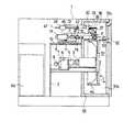
図1〜図4は本発明の摩擦試験機の一例を示し、ケーシング1内に立設された支持フレーム2の中間部に前後方向(図2の左右方向)に水平に延びるドラム回転軸3が回転自在に支持され、そのドラム回転軸3の先端部にドラム4が設けられている。ドラム回転軸3の後方の支持フレーム2上には、ドラム用の過負荷保護装置5と減速機6とが設置されている。減速機6に隣接して設置されたブレーキ機能を具備する駆動モータ7と減速機6とがベルト8を介して接続され、駆動モータ7の作動により、減速機6、過負荷保護装置5、ドラム回転軸3を介して、ドラム4が回転可能になっている。また、駆動モータ7にブレーキをかけた状態にすれば、ドラム4の回転を停止させることができる。ドラム4の制動手段は、特に限定されるものではなく、上記のように駆動モータ7にブレーキ機能を付加する以外に、ドラム回転軸3やドラム4にブレーキを付加しても良い。
【0016】
ドラム4の外周面4aには、エメリーペーパー等の研摩紙4bが着脱自在に張りつけられ、摩擦面4cを形成するようにしてある(図3)。ドラム4の前後幅が幅広に形成され、外周面4aにはゴム試験片Xが走行する複数(例えば10)のレーンを持つ摩擦面4cが形成できるようになっている。このように複数のレーンを有する摩擦面4cの形成により、研摩紙を張り替えることなく試験を連続して行うことができ、またゴム試験片Xの予備ずり(モールド表面に付いている油がゴム試験片に付着した際に、本試験前にゴム試験片Xを摩擦面4c上を転動させてその油を除去するなど)にも用いることができる。
【0017】
支持フレーム2の上端部に横設された水平板9上には、前後に延びるガイドレール10が固設され、このガイドレール10に板状の移動体11が摺動自在に係合している。移動体11の一側方の水平板9上にガイドレール10と平行に延びるボールネジ12が配設され、このボールネジ12に移動体11の一側に突設された係合部11aが螺合している。ボールネジ12の後端に連結されたモータ12aの駆動により、ボールネジ12が回転すると、移動体11がガイドレール10に沿って前後にドラム4の軸方向(ドラム回転軸3の延在する方向)と平行に移動するようになっている。
【0018】
移動体11の一側部には、前後(ドラム4の軸方向)に延びる支持壁13が垂直に立設されている。支持壁13の側面には、上下に延びるガイド部材14が前後2か所に固定され、これらガイド部材14,14に板状の昇降体15が上下に摺動自在に係合している。昇降体15の側部に突設された前後のブラケット16,17には、トルクメータ(トルク測定手段)18とブレーキ機能を具備した駆動モータ19が取り付けられている。この駆動モータ19は回転速度が制御自在に構成されている。駆動モータ19の回転軸19aにカップリングZとクラッチ20を介してトルクメータ18の後部回転軸18aが接続され、このトルクメータ18の前部回転軸18bに円板状のゴム試験片Xを保持する保持手段21の回転軸22が接続されている。この保持手段21は移動体11の移動に伴ってドラム4の軸方向に往復移動可能であるが、少なくとも摩擦試験時にはドラム4に対する相対的位置を軸方向に固定するようになっている。
【0019】
保持手段21は、図5に示すように、横設された円筒体23内に軸受24を介して支持された回転軸22の先端部22aにゴム試験片Xを着脱自在に保持可能な保持部25を備えている。この保持部25は、回転軸22の先端部22aに嵌着された保持軸26と、保持軸26の後端に突設されたフランジ27と、保持軸26に嵌合する芯金28と、芯金28を押さえる押さえフランジ29及び押さえキャップ31とを備えている。
【0020】
芯金28は外周面が周方向に凹凸状に形成され、その外周に内周面を周方向に凹凸状に形成して嵌合するようにしたゴム試験片Xが装着される。芯金28にゴム試験片Xを取り付け、その芯金28を保持軸26に嵌合させた後、芯金回り止めピン30を挿入し、押さえフランジ29と押さえキャップ31とを保持軸26の先端側からセットしてボルト31Aで固定することにより、保持部25にゴム試験片Xを保持するようにしてある。この保持部25は、ドラム4の上方に対設された位置となり、駆動モータ19の作動により回転するようになっている。
【0021】
支持壁13の前側上部側部にはブラケット32が突設され、このブラケット32に上方に突出する2本のロッド33aを伸縮自在に備えたシリンダ33の側部が固定されている。昇降体15の前側上部側部に水平に突設されたブラケット34には2本の支持棒35が垂直に立設固定され、この支持棒35の上端に固定されたプレート部材36の後部下面に上記ロッド33aの先端(上端)が固定されている。シリンダ33がオンになると、ロッド33aを図3に示すように縮小状態にし、ゴム試験片Xがドラム4の摩擦面4cに当接するように保持部25を試験位置に移動させる。一方、シリンダ33がオフになると、ロッド33aを伸長状態にし、ゴム試験片Xがドラム4の摩擦面4cから離間するように保持部25を待機位置に移動させる。また、プレート部材36の前部下面には、荷重シリンダ(荷重負荷手段)37が取り付けられ、その下方に突出するロッド37aの先端(下端)に押圧パッド37bが設けられている。
【0022】
円筒体23の先端部上部には荷重用部材40が上方に突設され、その前方に突出する水平板部40a上にロードセル(荷重検出手段)41が設置されている。このロードセル41の上方に上記荷重シリンダ37が位置し、ロッド37aを伸長して押圧パット37bによりロードセル41に荷重を加えることにより、荷重用部材40、円筒体23を介して、保持部25に装着されたゴム試験片Xに荷重を負荷できるようになっている。ロードセル41では、負荷された荷重が検出される。
【0023】
支持壁13の中央部上部側面には、所定の角度だけ回動自在な回動体42が突設され、この回動体42の前端部にはワイヤ43が吊設されている。他方、昇降体15の中央部上端にはフック44が突設され、このフック44にワイヤ43の下端部が取り付けられている。また、回動体42の後端に後方に向けて突設されたアーム部材45には重量体46がアーム部材45の長手方向に沿って摺動可能に取り付けられている。これら回動体42、ワイヤ43、フック44、アーム部材45及び重量体46は、試験片Xに対する負荷荷重を相殺するカウンターバランス47(荷重均衡手段)を構成している。即ち、カウンターバランス47は重量体46の重量に基づいて回動体42を矢印eの方向の回転させ、ワイヤ43を介して昇降体15を上方に引き上げるように作用するが、アーム部材45の長手方向に対する重量体46の位置を適切に調整することにより、試験片Xに対する負荷荷重を相殺するようになっている。そのため、荷重シリンダ37から与えられる荷重をロードセル41により正確に測定することが可能である。
【0024】
上記保持手段21とドラム4とは、断熱部材50で囲まれた恒温槽51内に配設されている。保持手段21とドラム4とは、保持部25に装着されたゴム試験片Xがドラム4と当接する部分に開口部を形成した仕切り板52により仕切られている。その仕切り板52には多数の貫通孔53が形成されている。
【0025】
保持手段21が配置された上部恒温室51aの壁面には、エアの供給口54が設けられている。この供給口54は不図示の配管を介してケーシング1の右側後部に設置されたエア供給源55に接続されている。エア供給源55では、ヒータにより外部から取り入れたエアを加熱し、また冷凍機により冷却し、エアを2℃〜60℃の範囲で温度調整でき、その温度調整されたエアを供給口54から上部恒温室51aに供給できるようになっている。供給口54から上部恒温室51aに供給されたエアは、仕切り板52の貫通孔53を通って下部恒温室51bの壁面に形成された排出口56から不図示のフィルターを介して外部に放出されるようにしてある。
【0026】
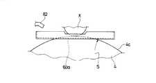
また、ドラム4とその上方の保持部25との間には、水張りトレイ60が設けられている。この水張りトレイ60は保持部25と共に前後に往復移動可能になっている。水張りトレイ60の底部には、図6に示すように、開口部60aが形成され、その開口部60aを介してドラム4の摩擦面と保持部25に保持されたゴム試験片Xが当接するように構成され、開口部60aとドラム4の摩擦面4cとの隙間sから水張りトレイ60に張られた水を下方に排出するようになっている。この隙間sは任意に調整可能になっている。
【0027】
一方、水張りトレイ60の上方には水を供給する給水部62が設けられている。この給水部62はケーシング1の左側後部に設置された水供給源63に接続され、通常は水張りトレイ60から排出される水よりも多くの水を供給できるようにしてある。但し、給水部62は必要に応じて供給水量を絞ることも可能である。水供給源63では水温コントローラにより水を2℃〜60℃の範囲で温度調整できるようになっている。
【0028】
下部恒温室51bの傾斜面に形成された床面51xには排出口64が形成され、この排出口64は水供給源63に接続されている。ドラム4の下方の床面51x上方には床面全面を覆うようにフィルター65が配設されている。水張りトレイ60の隙間sから流れ出た水は、フィルター65を介して排出口64から水供給源63に戻り、循環するようになっている。図中、70は試験片交換用ドア、71は研摩紙張替え用治具、72は研摩紙張替え用ドア、73は操作パネルである。
【0029】
上記摩擦試験機においては、待機位置で保持部25にゴム試験片Xを装着した後、シリンダ33を作動し、そのロッド33aを縮小した状態にする。それにより、昇降体15が降下して、保持部25に保持されているゴム試験片Xがドラム4の摩擦面4cに当接した状態になる(図3)。次いで、供給口54からエアを供給し、上部恒温室51a内が所定の試験温度になった後、荷重シリンダ37を押圧作動し、ゴム試験片Xに所定の負荷を与える。ウェット時の摩擦係数を測定する場合には、水張りトレイ60に給水部62から所定の温度の水を供給し、所定の水深となるように水を張るようにする。
【0030】
タイヤ制動時のスリップ条件における摩擦係数を測定する場合は、保持手段21の位置を軸方向に固定した状態で駆動モータ7,19の回転速度をそれぞれ制御し、ドラム4を一定の回転速度に保持する一方で、保持手段21をゴム試験片Xの表面速度とドラム4の表面速度とを等速にする回転速度から停止状態まで減速し、そのスリップ率を0%から100%まで連続的に変化させる。このとき、ロードセル41で検出された荷重データとトルクメータ18で検出されたトルクデータは不図示のコンピュータに順次送られ、そこで各スリップ率に応じた摩擦係数がそれぞれ算出され、摩擦係数−スリップ率曲線(μ−Sカーブ)が求められる。従って、スリップ率を0〜100%まで変化させた時の摩擦係数−スリップ率の関係をゴム試験片の段階で正確に測定することができる。
【0031】
また、タイヤ間欠制動時のスリップ条件における摩擦係数を測定する場合は、保持手段21の位置を軸方向に固定した状態で駆動モータ7,19の回転速度をそれぞれ制御し、ドラム4を一定の回転速度に保持する一方で、保持手段21をゴム試験片Xの表面速度とドラム4の表面速度とを等速にする回転速度を上限として繰り返し加減速し、スリップ率0〜100%の任意の範囲で、より好ましくは0〜20%の範囲で連続的に変化させ、上記と同様にスリップ率に応じた摩擦係数を求めるようにする。一般に、ABS(アンチロックブレーキ装置)を採用した自動車では、タイヤのスリップ率が例えば0〜20%の範囲で変化するような間欠制動が行われるが、上記摩擦試験方法では、上記タイヤ間欠制動時のスリップ条件を再現し、そのスリップ条件での摩擦係数を正確に測定することができる。
【0032】
また、実車により近いABS制動時のスリップ条件を再現しながら摩擦係数を測定したい場合は、保持手段21の位置を軸方向に固定した状態で駆動モータ7,19の回転速度をそれぞれ制御し、ドラム4を特定の回転速度から減速する一方で、保持手段21をゴム試験片Xの表面速度とドラム4の表面速度とを等速にする回転速度を上限として繰り返し加減速し、スリップ率0〜100%の任意の範囲で、より好ましくは0〜20%の範囲で連続的に変化させ、上記と同様にスリップ率に応じた摩擦係数を求めるようにする。実車ではタイヤが制動しながら減速するため、上記摩擦試験方法によれば実車により近いスリップ条件を再現することが可能になる。
【0033】
更に、タイヤ発進時のスリップ条件における摩擦係数を測定する場合は、保持手段21の位置を軸方向に固定した状態で駆動モータ7,19の回転速度をそれぞれ制御し、ドラム4を停止状態に保持する一方で、保持手段21を停止状態から回転駆動し、そのときの摩擦係数を求めるようにする。この場合、タイヤ発進時のスリップ条件を再現し、そのスリップ条件での摩擦係数を正確に測定することができる。
【0034】
上記試験終了後においては、昇降体15を引き上げてゴム試験片Xを装着した保持部25を待機位置に移動させる。別のゴム試験片Xを続けて試験する場合には、保持部25のゴム試験片Xを交換し、モータ12aの作動によりボールネジ12を回転させ、移動体11をガイドレール10に沿って移動させて、保持部25のゴム試験片Xを次の摩擦面(レーン)4c上に移動させた後、上記と同様にして試験を行う。
【0035】
本発明において、上記ドラム4の外周面4aの直径としては、ゴム試験片Xの直径の5倍以上、好ましくは10倍以上にするのが良い。この外周面4aの外径は500〜3000mmにすることが好ましく、例えば外径1000mmにすることができる。このように試験片に対して径を大きくした大径のドラム4の使用により、外周面4aの曲率の影響を抑えて実路面に近い状態にすると共に、試験中に走行した同じ摩擦面上をゴム試験片Xが走行する回数を少なくし、試験片の摩耗による摩擦面の状態変化を抑えることが可能になるので、摩擦力の測定をより正確に行うことができる。
【0036】
ドラム4の摩擦面4cを形成する研摩紙4bは、実路面に応じた粗さを持つものを使用することが好ましく、エメリーペーパーとしては粗さが#80〜#800のものを好ましく使用することができる。
【0037】
上述したゴム試験片Xの寸法としては、外径30〜200mmにすることが好ましく、例えば外径100mmにすることができる。また、ゴム試験片Xの幅は10〜20mmにすることができる。その試験片を取り付ける芯金28の外径(凸部における外径)としては、例えば、70mmにすることができる。
【0038】
本発明の摩擦試験機は、上述したように試験片にゴム試験片を使用し、ゴムの摩擦係数(特に、空気入りタイヤに使用されるゴムの摩擦係数)を測定する場合に好ましく用いることができるが、それに限定されず、合成樹脂等の弾性体からなる試験片を用いて、その摩擦係数を測定するようにしても良い。
【0039】
【発明の効果】
上述したように本発明によれば、試験片の保持手段及びドラムの回転速度をそれぞれ制御自在に構成すると共に、少なくとも摩擦試験時には保持手段の位置を軸方向に固定するようにしたので、任意のスリップ条件を設定可能であり、そのスリップ条件において試験片の摩擦係数を正確に測定することができる。
また、保持手段及びその駆動モータ等を搭載する昇降体を上下方向に進退自在に構成することにより、試験片の大きさが種々異なる場合であっても、ドラムの回転軸と保持手段の回転軸との平行状態を維持し、測定条件を一定にすることができる。更に、支持壁に試験片に対する負荷荷重を相殺する荷重均衡手段を設けることにより、荷重負荷手段から与えられる荷重を荷重検出手段により正確に測定することができる。
【図面の簡単な説明】
【図1】本発明の摩擦試験機の一例を示す正面図である。
【図2】図1の側断面図である。
【図3】図2の要部拡大図である。
【図4】図3の平面図である。
【図5】(a)は保持手段の拡大断面図、(b)は保持手段の芯金に試験片を装着した状態を示す説明図である。
【図6】水張りトレイの説明図である。
【符号の説明】
3 ドラム回転軸
4 ドラム
4a 外周面
4c 摩擦面
7,19 駆動モータ
11 移動体
13 支持壁
15 昇降体
18 トルクメータ(トルク測定手段)
21 保持手段
22 回転軸
37 荷重シリンダ(荷重負荷手段)
41 ロードセル(荷重検出手段)
47 カウンターバランス(荷重均衡手段)
51 恒温槽
60 水張りトレイ
60a 開口部
62 給水部
63 水供給源
s 隙間
X ゴム試験片[0001]
BACKGROUND OF THE INVENTION
The present invention relates to a friction tester for measuring the friction characteristics of a rubber test piece and a friction test method using the friction tester, and more particularly, friction that enables accurate measurement of a friction coefficient under various slip conditions. The present invention relates to a testing machine and a friction test method.
[0002]
[Prior art]
For example, rubber used for a pneumatic tire is examined by a laboratory test at the stage of a test piece in order to predict a friction coefficient during actual vehicle travel. Generally, the friction tester used for the test is a jig configured to be rotatable, as shown in Japanese Patent Publication No. 53-34752, Japanese Patent Laid-Open No. 4-215038, Japanese Patent Publication No. 60-149946. The test piece is fixed and pressed against the road surface while rotating the test piece, or the fixed test piece is pressed against the rotating friction surface of the drum to measure the friction coefficient. Therefore, only a friction coefficient with a constant slip ratio can be obtained, and the relationship between the friction coefficient and the slip ratio when the slip ratio is changed from 0 to 100% cannot be obtained.
[0003]
On the other hand, in Japanese Patent Laid-Open No. 1-292232, on the friction surface provided on the outer peripheral surface of the rotatable drum, the rotating test piece is rotated in the drum axis direction while changing the rotation speed so that the slip ratio changes. A testing machine that measures frictional characteristics by moving to a position is disclosed. However, the above-mentioned testing machine has a problem in that since the test piece is moved in the axial direction on the drum at the time of measurement, a lateral force is generated on the rubber test piece and an accurate friction coefficient cannot be measured.
[0004]
[Problems to be solved by the invention]
An object of the present invention is to provide a friction tester and a friction test method capable of setting an arbitrary slip condition and accurately measuring a friction coefficient under the slip condition.
[0005]
[Means for Solving the Problems]
The friction tester of the present invention that achieves the above object includes a rotating shaft of a drum having a friction surface on an outer peripheral surface, and a rotating shaft of a holding means for holding a disk-shaped test piece that rotates while contacting the friction surface. Are arranged in parallel with each other, and the rotational speeds of the drum and the holding means are configured to be controllable, torque measuring means for measuring torque applied to the holding means, and load loading means for applying a load to the test piece And a load detecting means for detecting the load, the position of the holding means is fixed in the axial direction at least during a friction test, and the holding means is disposed above the drum, and the shaft of the drum A support wall is erected on a movable body that can move in parallel in the direction, and an elevating body that can be moved up and down along the support wall is disposed. The elevating body is interposed with the holding means and the torque measuring means. The above And a load balancing means for canceling a load applied to the test piece is provided on the support wall, and the load loading means is installed on the lifting body, and the load loading means The load is applied to the holding means through the load detection means .
[0006]
In this way, by configuring the test piece holding means and the drum rotation speed to be controllable, an arbitrary slip condition is set based on the speed ratio between the surface speed of the drum and the surface speed of the test piece. The coefficient of friction of the test piece can be measured under slip conditions. Further, since the position of the holding means is fixed in the axial direction at least during the friction test, the relationship between the friction coefficient and the slip ratio can be accurately obtained without the test piece receiving a lateral force during the test.
[0007]
In the present invention, the diameter of the outer peripheral surface of the drum is preferably 5 times or more the diameter of the test piece. By making the drum relatively large compared to the test piece in this way, even when the position of the holding means is fixed in the axial direction during the friction test as described above, oil or rubber scraps adhere to the friction surface. It is possible to complete the friction test before the state change due to. In addition, if a friction surface having a plurality of lanes on which the test piece travels is provided on the outer peripheral surface of the drum and the test piece is configured to be movable for each lane, the friction test of the test piece can be continuously performed only by changing the lane. It can be carried out.
[0008]
In the present invention, holding means is disposed above the drum, a support wall is erected on a movable body that can move in parallel with the axial direction of the drum, and an elevating body that can be moved up and down along the support wall is disposed. The lifting body is equipped with a holding means and a drive motor for driving the holding means via the torque measuring means, and a load balancing means for canceling the load applied to the test piece is provided on the support wall. It isnecessary to install a load loading means and to apply a load to the holding means via the load detection means.
[0009]
In this way, by constructing the elevating body on which the holding means and its drive motor are mounted so as to be able to advance and retreat in the vertical direction, the rotation axis of the drum and the rotation of the holding means can be obtained even when the sizes of the test pieces are different. The measurement condition can be made constant while maintaining a parallel state with the axis. Further, by providing a load balancing means for canceling the load applied to the test piece on the support wall, the load applied from the load loading means can be accurately measured by the load detection means.
[0010]
Also, holding means is arranged above the drum via a water-filled tray, an opening is formed at the bottom of the water-filled tray, and the test piece held by the friction surface of the drum and the holding means is applied through the opening. A water supply unit that supplies water to the water-filled tray may be provided, and water stretched on the water-filled tray may be discharged from a gap between the opening of the water-filled tray and the friction surface of the drum. By providing this water-filled tray, it is possible to measure the coefficient of friction under wet conditions. In this case, it is preferable that the amount of water supplied from the water supply unit can be adjusted, and the gap between the opening of the water-filled tray and the friction surface of the drum can be adjusted. Moreover, it is good to connect the water supply source which can adjust water temperature to a water supply part.
[0011]
Furthermore, a holding means may be installed in the thermostat so that the temperature-controlled air can be supplied to the thermostat. By providing this constant temperature bath, the temperature condition can be set accurately.
[0012]
On the other hand, the friction test method of the present invention uses the above-described friction tester to set an arbitrary slip condition based on the speed difference between the surface speed of the drum and the surface speed of the test piece, and the friction under the slip condition. The coefficient is measured.
[0013]
More specifically, while holding the drum at a constant rotation speed, the holding means is decelerated from a rotation speed at which the surface speed of the test piece and the surface speed of the drum are equal to a stop state, and a slip ratio of 0 to While reproducing the slip conditions during tire braking in the range of 100% and holding the drum at a constant rotation speed, the holding means has a rotation speed that makes the surface speed of the test piece and the surface speed of the drum constant. Accelerate and decelerate repeatedly as the upper limit, reproduce the slip condition at the time of intermittent braking of the tire (at the time of ABS braking) in an arbitrary range of slip rate 0 to 100%, decelerate the drum from a specific rotation speed, Acceleration / deceleration is repeated up to the upper limit of the rotation speed at which the surface speed of the test piece and the surface speed of the drum are equal, and the tire is intermittently braked in any range with a slip rate of 0 to 100% (at the time of ABS braking closer to the actual vehicle). While reproducing the slip conditions or holding the drum in the stopped state, the holding means is rotated from the stopped state to reproduce the slip conditions at the start of the tire, and the friction coefficient is accurately measured under these slip conditions. I can.
[0014]
DETAILED DESCRIPTION OF THE INVENTION
Hereinafter, the configuration of the present invention will be described in detail with reference to the accompanying drawings.
[0015]
1 to 4 show an example of a friction tester according to the present invention. A
[0016]
[0017]
A
[0018]
A
[0019]
As shown in FIG. 5, the holding means 21 is a holding portion capable of detachably holding the rubber test piece X at the
[0020]
The
[0021]
A
[0022]
A
[0023]
On the upper side surface of the central portion of the
[0024]
The holding means 21 and the drum 4 are disposed in a
[0025]
An
[0026]
Further, a water-filled
[0027]
On the other hand, a
[0028]
A
[0029]
In the friction tester, after the rubber test piece X is mounted on the holding
[0030]
When measuring the friction coefficient under slip conditions during tire braking, the rotational speed of the
[0031]
When measuring the coefficient of friction under slip conditions during intermittent braking of the tire, the rotational speed of the
[0032]
Also, when it is desired to measure the friction coefficient while reproducing the slip condition at the time of ABS braking closer to the actual vehicle, the rotational speeds of the
[0033]
Further, when measuring the friction coefficient under the slip condition at the start of the tire, the rotational speed of the
[0034]
After the end of the test, the elevating
[0035]
In the present invention, the diameter of the outer
[0036]
The
[0037]
The size of the rubber test piece X described above is preferably set to an outer diameter of 30 to 200 mm, for example, an outer diameter of 100 mm. Moreover, the width | variety of the rubber test piece X can be 10-20 mm. The outer diameter of the
[0038]
The friction tester of the present invention is preferably used when a rubber test piece is used as a test piece as described above and the friction coefficient of rubber (particularly, the friction coefficient of rubber used for a pneumatic tire) is measured. However, the present invention is not limited to this, and the coefficient of friction may be measured using a test piece made of an elastic body such as a synthetic resin.
[0039]
【The invention's effect】
As described above, according to the present invention, the holding means of the test piece and the rotational speed of the drum are configured to be controllable, and at least during the friction test, the position of the holding means is fixed in the axial direction. The slip condition can be set, and the friction coefficient of the test piece can be accurately measured under the slip condition.
In addition, by constructing the lifting and lowering body on which the holding means and the drive motor thereof are mounted so as to be able to advance and retreat in the vertical direction, the drum rotation shaft and the rotation shaft of the holding means can be used even when the sizes of the test pieces are different. The measurement condition can be made constant while maintaining a parallel state. Furthermore, by providing a load balance means for canceling the load applied to the test piece on the support wall, the load applied from the load load means can be accurately measured by the load detection means.
[Brief description of the drawings]
FIG. 1 is a front view showing an example of a friction tester of the present invention.
FIG. 2 is a side sectional view of FIG.
FIG. 3 is an enlarged view of a main part of FIG. 2;
4 is a plan view of FIG. 3;
5A is an enlarged cross-sectional view of the holding means, and FIG. 5B is an explanatory view showing a state in which a test piece is mounted on the metal core of the holding means.
FIG. 6 is an explanatory diagram of a water filled tray.
[Explanation of symbols]
3 drum rotation shaft 4
21 Holding means 22 Rotating
41 Load cell (load detection means)
47 Counterbalance (load balancing means)
51
Claims (12)
Translated fromJapanesePriority Applications (1)
| Application Number | Priority Date | Filing Date | Title |
|---|---|---|---|
| JP14228199AJP3878768B2 (en) | 1999-05-21 | 1999-05-21 | Friction tester and friction test method |
Applications Claiming Priority (1)
| Application Number | Priority Date | Filing Date | Title |
|---|---|---|---|
| JP14228199AJP3878768B2 (en) | 1999-05-21 | 1999-05-21 | Friction tester and friction test method |
Publications (2)
| Publication Number | Publication Date |
|---|---|
| JP2000329687A JP2000329687A (en) | 2000-11-30 |
| JP3878768B2true JP3878768B2 (en) | 2007-02-07 |
Family
ID=15311726
Family Applications (1)
| Application Number | Title | Priority Date | Filing Date |
|---|---|---|---|
| JP14228199AExpired - Fee RelatedJP3878768B2 (en) | 1999-05-21 | 1999-05-21 | Friction tester and friction test method |
Country Status (1)
| Country | Link |
|---|---|
| JP (1) | JP3878768B2 (en) |
Families Citing this family (13)
| Publication number | Priority date | Publication date | Assignee | Title |
|---|---|---|---|---|
| JP4591218B2 (en)* | 2005-06-08 | 2010-12-01 | 横浜ゴム株式会社 | Friction testing machine |
| JP2007017423A (en)* | 2005-06-08 | 2007-01-25 | Yokohama Rubber Co Ltd:The | Friction test method and friction tester |
| JP4665743B2 (en)* | 2005-12-09 | 2011-04-06 | 横浜ゴム株式会社 | Method for evaluating friction characteristics of rubber material on wet road surface |
| JP4771175B2 (en)* | 2007-06-18 | 2011-09-14 | 横浜ゴム株式会社 | Method and apparatus for measuring sliding friction force of tire |
| KR101247630B1 (en) | 2010-11-17 | 2013-03-29 | 한국타이어월드와이드 주식회사 | A calculating method of the coefficient of the friction at the contact surface of the rubber block |
| JP6509595B2 (en)* | 2015-03-16 | 2019-05-08 | 住友ゴム工業株式会社 | Adhesion test method for tire rubber |
| CN106679947B (en)* | 2016-11-30 | 2019-08-13 | 国机智能科技有限公司 | Seal friction process on-line intelligence checkout and diagnosis pilot system |
| JP2019049440A (en) | 2017-09-08 | 2019-03-28 | Toyo Tire株式会社 | Rubber friction test method |
| CN108717017B (en)* | 2018-08-07 | 2025-03-04 | 上海海事大学 | Polar navigation ship material low temperature environment friction and collision performance test device |
| CN111855468B (en)* | 2020-08-04 | 2025-09-09 | 西华大学 | Multifunctional pin-disc type abrasion simulation experiment device |
| CN113267418B (en)* | 2021-06-28 | 2023-01-10 | 青岛征和工业股份有限公司 | Chain hinge pair wear resistance test device and method |
| CN115165650B (en)* | 2022-08-22 | 2023-07-28 | 郑州天源橡胶有限公司 | Intelligent detection equipment for high polymer rubber products |
| CN116297162B (en)* | 2023-05-17 | 2023-08-01 | 成都理工大学 | Device and method for testing friction coefficient of discrete particle plugging material |
Family Cites Families (7)
| Publication number | Priority date | Publication date | Assignee | Title |
|---|---|---|---|---|
| JPS58187757U (en)* | 1982-06-08 | 1983-12-13 | 横浜ゴム株式会社 | Viscoelastic body wear test device |
| JPH01141336A (en)* | 1987-11-27 | 1989-06-02 | Bridgestone Corp | Frictional wear testing instrument |
| JP2595040B2 (en)* | 1988-05-20 | 1997-03-26 | 株式会社ブリヂストン | Friction and wear testing machine |
| JPH02210243A (en)* | 1989-02-10 | 1990-08-21 | Tokyo Silicone Kk | Frictional wear testing machine |
| JPH0634507A (en)* | 1992-07-17 | 1994-02-08 | Yokohama Rubber Co Ltd:The | Wear test device |
| JPH08145866A (en)* | 1994-11-22 | 1996-06-07 | Yokohama Rubber Co Ltd:The | Moistening abrasion testing machine |
| JP3320654B2 (en)* | 1998-05-08 | 2002-09-03 | 株式会社ブリヂストン | Rubber wear measurement method |
- 1999
- 1999-05-21JPJP14228199Apatent/JP3878768B2/ennot_activeExpired - Fee Related
Also Published As
| Publication number | Publication date |
|---|---|
| JP2000329687A (en) | 2000-11-30 |
Similar Documents
| Publication | Publication Date | Title |
|---|---|---|
| JP3878768B2 (en) | Friction tester and friction test method | |
| US11067489B2 (en) | Device for measuring rubber wear | |
| US6050876A (en) | Automated abrader | |
| JP3739029B2 (en) | Friction test equipment | |
| JP4963978B2 (en) | Rubber abrasion tester and tire tread rubber abrasion test method using the same | |
| KR20210001208A (en) | Hybrid simulator for braking and tire driving and method of measuring brake and tire fine dust | |
| JP2000002641A5 (en) | ||
| JP2000002641A (en) | Wear test equipment | |
| JP3320654B2 (en) | Rubber wear measurement method | |
| JP4591218B2 (en) | Friction testing machine | |
| KR200461460Y1 (en) | Device for measuring horizontal friction of tire | |
| JP3706637B2 (en) | Viscoelastic body wear test equipment | |
| JP2007017423A (en) | Friction test method and friction tester | |
| JP4172526B2 (en) | Abrasion test equipment | |
| CN206192804U (en) | Multistation rubber abrasion tester | |
| JP4079703B2 (en) | Indoor tire durability test method | |
| JP2016057233A (en) | Tire hydroplaning performance evaluation method | |
| JP2007279062A (en) | Abrasion test equipment | |
| JP2004306273A (en) | Method and apparatus for applying release agent to tire vulcanizing bladder | |
| KR20010082406A (en) | Auto mesuring system for DTV of brake disk/drum in car | |
| JP2002214102A (en) | Load moving test device | |
| JPS6113131A (en) | Operation checking method of antiskid valve utilizing brake tester | |
| RU119879U1 (en) | STAND FOR STUDYING THE WORKING PROCESS OF A WHEEL VEHICLE MOTOR | |
| KR200248436Y1 (en) | Auto mesuring system for DTV of brake/drum in car | |
| JPH03165233A (en) | Friction and wear testing device |
Legal Events
| Date | Code | Title | Description |
|---|---|---|---|
| A621 | Written request for application examination | Free format text:JAPANESE INTERMEDIATE CODE: A621 Effective date:20050215 | |
| A977 | Report on retrieval | Free format text:JAPANESE INTERMEDIATE CODE: A971007 Effective date:20060720 | |
| A131 | Notification of reasons for refusal | Free format text:JAPANESE INTERMEDIATE CODE: A131 Effective date:20060801 | |
| A521 | Written amendment | Free format text:JAPANESE INTERMEDIATE CODE: A523 Effective date:20060929 | |
| TRDD | Decision of grant or rejection written | ||
| A01 | Written decision to grant a patent or to grant a registration (utility model) | Free format text:JAPANESE INTERMEDIATE CODE: A01 Effective date:20061031 | |
| A61 | First payment of annual fees (during grant procedure) | Free format text:JAPANESE INTERMEDIATE CODE: A61 Effective date:20061106 | |
| R150 | Certificate of patent or registration of utility model | Free format text:JAPANESE INTERMEDIATE CODE: R150 | |
| S111 | Request for change of ownership or part of ownership | Free format text:JAPANESE INTERMEDIATE CODE: R313117 | |
| FPAY | Renewal fee payment (event date is renewal date of database) | Free format text:PAYMENT UNTIL: 20091110 Year of fee payment:3 | |
| R350 | Written notification of registration of transfer | Free format text:JAPANESE INTERMEDIATE CODE: R350 | |
| FPAY | Renewal fee payment (event date is renewal date of database) | Free format text:PAYMENT UNTIL: 20091110 Year of fee payment:3 | |
| FPAY | Renewal fee payment (event date is renewal date of database) | Free format text:PAYMENT UNTIL: 20101110 Year of fee payment:4 | |
| FPAY | Renewal fee payment (event date is renewal date of database) | Free format text:PAYMENT UNTIL: 20111110 Year of fee payment:5 | |
| FPAY | Renewal fee payment (event date is renewal date of database) | Free format text:PAYMENT UNTIL: 20121110 Year of fee payment:6 | |
| FPAY | Renewal fee payment (event date is renewal date of database) | Free format text:PAYMENT UNTIL: 20121110 Year of fee payment:6 | |
| FPAY | Renewal fee payment (event date is renewal date of database) | Free format text:PAYMENT UNTIL: 20131110 Year of fee payment:7 | |
| R250 | Receipt of annual fees | Free format text:JAPANESE INTERMEDIATE CODE: R250 | |
| S111 | Request for change of ownership or part of ownership | Free format text:JAPANESE INTERMEDIATE CODE: R313111 | |
| R360 | Written notification for declining of transfer of rights | Free format text:JAPANESE INTERMEDIATE CODE: R360 | |
| R370 | Written measure of declining of transfer procedure | Free format text:JAPANESE INTERMEDIATE CODE: R370 | |
| S531 | Written request for registration of change of domicile | Free format text:JAPANESE INTERMEDIATE CODE: R313531 | |
| S533 | Written request for registration of change of name | Free format text:JAPANESE INTERMEDIATE CODE: R313533 | |
| R350 | Written notification of registration of transfer | Free format text:JAPANESE INTERMEDIATE CODE: R350 | |
| R250 | Receipt of annual fees | Free format text:JAPANESE INTERMEDIATE CODE: R250 | |
| R250 | Receipt of annual fees | Free format text:JAPANESE INTERMEDIATE CODE: R250 | |
| LAPS | Cancellation because of no payment of annual fees |