JP3878508B2 - Circuit group control system - Google Patents
Circuit group control systemDownload PDFInfo
- Publication number
- JP3878508B2 JP3878508B2JP2002124877AJP2002124877AJP3878508B2JP 3878508 B2JP3878508 B2JP 3878508B2JP 2002124877 AJP2002124877 AJP 2002124877AJP 2002124877 AJP2002124877 AJP 2002124877AJP 3878508 B2JP3878508 B2JP 3878508B2
- Authority
- JP
- Japan
- Prior art keywords
- command
- memory
- circuit
- execution
- sequence
- Prior art date
- Legal status (The legal status is an assumption and is not a legal conclusion. Google has not performed a legal analysis and makes no representation as to the accuracy of the status listed.)
- Expired - Fee Related
Links
Images


Classifications
- G—PHYSICS
- G06—COMPUTING OR CALCULATING; COUNTING
- G06F—ELECTRIC DIGITAL DATA PROCESSING
- G06F9/00—Arrangements for program control, e.g. control units
- G06F9/06—Arrangements for program control, e.g. control units using stored programs, i.e. using an internal store of processing equipment to receive or retain programs
- G06F9/46—Multiprogramming arrangements
- G06F9/48—Program initiating; Program switching, e.g. by interrupt
- G06F9/4806—Task transfer initiation or dispatching
- G06F9/4843—Task transfer initiation or dispatching by program, e.g. task dispatcher, supervisor, operating system
Landscapes
- Engineering & Computer Science (AREA)
- Software Systems (AREA)
- Theoretical Computer Science (AREA)
- Physics & Mathematics (AREA)
- General Engineering & Computer Science (AREA)
- General Physics & Mathematics (AREA)
- Multi Processors (AREA)
- Advance Control (AREA)
- Bus Control (AREA)
Description
Translated fromJapanese【0001】
【発明の属する技術分野】
本発明は、プロセッサその他の回路の集合である回路群の制御を行う技術に関し、特に、あるプロセッサからコマンドを受けて、コマンドに対応した処理を回路群中の各回路に行わせる回路群制御システムに関する。
【0002】
【従来の技術】
従来、ある1つのプロセッサ(以下、「マスタプロセッサ」という。)が、他のプロセッサ(以下、「スレーブプロセッサ」という。)、DMAコントローラ等の回路にコマンドを伝えることにより処理の実行を依頼する方式が知られている。以下、マスタプロセッサから処理の実行を依頼されるスレーブプロセッサやDMAコントローラ等の回路を、「スレーブハード(slave hardware)」という。
【0003】
この方式により、マスタプロセッサとスレーブハードとは並行動作を行うことが可能となるため、マスタプロセッサが解読実行の対象とするプログラムによる情報処理の迅速化を図ることができる。
ところで、複数のスレーブハードそれぞれに対応する複数のコマンドが、一定の順序で実行されることにより、一定目的が達成される場合がある。
【0004】
そこで、マスタプロセッサが複数のコマンドの一定順序での実行を内容とする処理をスレーブハード群に一括して依頼すべく、いずれかのスレーブハードの実行対象となるコマンドを複数個順序付けてなるコマンド列をスレーブハード群の制御機構に伝達し、これを受けて、その制御機構がコマンド列の各コマンドを順に解読して、対応するスレーブハードを特定してそのスレーブハードにコマンドに対応する処理を行わせるといった方式が、マスタプロセッサに関わるコマンド授受手順のオーバヘッドを低減させる点で、情報処理をより迅速に実行するために有効となる。
【0005】
なお、コマンド列は、例えば、DMAコントローラに、主メモリからローカルメモリへの数百キロバイト(KB)程度の一群のデータを転送させる指示を内容とするコマンドA、スレーブプロセッサにローカルメモリ中のその一群のデータに基づいて所定の演算を実行しその結果となる一群のデータをローカルメモリに格納させる指示を内容とするコマンドB、及び演算結果である一群のデータをDMAコントローラにローカルメモリ中から主メモリに転送させる指示を内容とするコマンドCがこの順に実行されるように結び付けられて構成される。
【0006】
この例示したコマンド列をマスタプロセッサから受けた場合に、スレーブハード群の制御機構は、まずコマンドAに対応する処理AをDMAコントローラに行わせ、処理Aが完了した後に、コマンドBに対応する処理Bをスレーブプロセッサに行わせ、処理Bが完了した後に、コマンドCに対応する処理CをDMAコントローラに行わせる。
【0007】
また、マスタプロセッサは、実行対象とする情報処理が複数のタスクとして扱える場合等において、複数のコマンド列をスレーブハード群に随時実行させる必要があるときがある。
このとき、マスタプロセッサは、複数のスレーブハードの連携的動作を指示するコマンド列を2つ以上、スレーブハード群の制御機構に伝達する。また、普通に考えられるスレーブハード群の制御機構は、1つのコマンド列に着目しそのコマンド列を構成するコマンドを順に、対応するスレーブハードに処理させることをコマンド数分繰り返し、続いて別のコマンド列に着目して同様な処理手順を実行する。
【0008】
【発明が解決しようとする課題】
しかしながら、上述したスレーブハード群の制御機構は、マスタプロセッサから受け取ったコマンド列中の各コマンドに順次着目して、着目したコマンドに対応するスレーブハードにそのコマンドの処理を行わせる手順を繰り返すため、各時刻においては、スレーブハード群のうちの1つのスレーブハードのみが稼働していることになり、スレーブハードの有効活用が図れていない。
【0009】
そこで、本発明は、マスタプロセッサから受け取った複数のコマンド列に対応する処理を各スレーブハードに行わせる際に、各スレーブハードの稼働率を上げるための制御を行う制御機構を含む回路群制御システムを提供することを目的とする。
また、本発明は、上述の回路群制御システムを構築する場合において有用な各種技術を提供することをも目的とする。
【0010】
【課題を解決するための手段】
上記目的を達成するために本発明に係る回路群制御システムは、マスタプロセッサからの指定を受けて、相互に異なる機能を有する複数の回路を制御する回路群制御システムであって、前記複数の回路のいずれかに実行させるべきコマンドを複数ならべて構成されるコマンド列の複数個の指定をマスタプロセッサから受け付けるコマンド列指定受付手段と、コマンド列指定受付手段により受け付けられた指定に係るコマンド列に従った順序で各コマンド列内のコマンドを逐次、当該コマンドを実行し得る回路に実行させる実行制御手段とを備え、前記実行制御手段は、一の回路に一のコマンド列中のコマンドを実行させている間において、他のコマンド列中の、他の回路により実行され得る状態にあるコマンドを選択して当該他の回路に実行させる並列実行制御部を含むことを特徴とする。
【0011】
また、本発明に係る回路群制御方法は、マスタプロセッサからの指定に基づいて、相互に異なる機能を有する複数の回路を制御する回路群制御方法であって、前記複数の回路のいずれかに実行させるべきコマンドを複数ならべて構成されるコマンド列の複数個の指定をマスタプロセッサから受け付けるコマンド列指定受付ステップと、コマンド列指定受付ステップにより受け付けられた指定に係るコマンド列に従った順序で各コマンド列内のコマンドを逐次、当該コマンドを実行し得る回路に実行させる実行制御ステップとを含み、前記実行制御ステップは、一の回路に一のコマンド列中のコマンドを実行させている間において、他のコマンド列中の、他の回路により実行され得る状態にあるコマンドを選択して当該他の回路に実行させる並列実行制御サブステップを含むことを特徴とする。
【0012】
これらにより、複数のコマンド列のコマンドを各回路、つまり各スレーブハードに行わせる際に、異なるスレーブハードにより複数のコマンドを並行させるため、各スレーブハードの稼働率を上げることが可能になる。
また、本発明に係る回路群制御システムは、マスタプロセッサからの指定を受けて、複数の回路を制御する回路群制御システムであって、前記複数の回路のいずれかに実行させるべきコマンドを複数ならべて構成されるコマンド列の複数個の指定をマスタプロセッサから受け付けるコマンド列指定受付手段と、コマンド列指定受付手段により受け付けられた指定に係るコマンド列に従った順序で各コマンド列内のコマンドを逐次、当該コマンドを実行し得る回路に実行させる実行制御手段とを備え、前記コマンド列指定受付手段は、コマンド格納用メモリを有し、前記マスタプロセッサによりコマンド格納用メモリに複数のコマンドが書き込まれることを通じて前記コマンド列の指定を受け付け、前記実行制御手段は、コマンド格納用メモリに書き込まれたコマンドを、コマンド列に従った順序で逐次参照して、参照した当該コマンドを実行し得る回路に実行させることを特徴とする。
【0013】
上記構成により、マスタプロセッサが複数のコマンドからなるコマンド列を一括して回路群制御システムに伝えることができるので基本的には同期制御が不要となり、逐次コマンドを伝える場合よりも、コマンドを伝えるための制御が容易となる。
また、本発明に係る回路群制御システムは、マスタプロセッサからの指定を受けて、複数の回路を制御する回路群制御システムであって、前記複数の回路のいずれかに実行させるべきコマンドを複数ならべて構成されるコマンド列の複数個の指定をマスタプロセッサから受け付けるコマンド列指定受付手段と、コマンド列指定受付手段により受け付けられた指定に係るコマンド列に従った順序で各コマンド列内のコマンドを逐次、当該コマンドを実行し得る回路に実行させる実行制御手段と、前記マスタプロセッサからコマンドの実行完了の通知要求を受け付ける実行完了通知受付手段と、前記実行制御手段によりコマンドを実行させた回路から当該コマンドを実行完了した旨の通知を受け付けて、当該コマンドが前記実行完了通知受付手段により受け付けられた通知要求に係るコマンドである場合には、当該コマンドの実行完了を前記マスタプロセッサに通知する実行完了通知手段とを備えることを特徴とする。
【0014】
上記構成により、マスタプロセッサは特定のコマンドの実行完了を検出することができるようになるため、例えば同期をとる必要がある複数のコマンド列により成立するような情報処理を、回路群制御システムを用いて実行することができるようになる。
【0015】
【発明の実施の形態】
以下、本発明の回路群制御システムについての実施の形態である処理システムについて図面を用いて説明する。
<実施の形態1>
<1-1.構成概要>
図1は、本発明の実施の形態1に係る処理システム100の構成図である。
【0016】
処理システム100は、マスタプロセッサが情報処理を行うに際して、スレーブプロセッサ又はDMAコントローラといったスレーブハードに部分的処理を依頼することを可能にしたシステムであり、同図に示すようにマスタプロセッサ110、主メモリ120、スレーブプロセッサ130、ローカルメモリ131、DMAコントローラ140及びコマンド実行制御装置150を備え、半導体の1チップ内に形成されている。
【0017】
ここで、マスタプロセッサ110はアプリケーションプログラムその他のプログラムで特定された情報処理を実行するプロセッサである。なお、この情報処理は、スレーブプロセッサ用のコマンドとDMAコントローラ用のコマンドとが一定順序で組み合わされたコマンド列によって実現される一定単位の部分的処理の集合である。
【0018】
プログラムを実行することによってマスタプロセッサ110は、スレーブハードに部分的処理を行わせるために、コマンド実行制御装置150に随時、コマンド列を伝え、必要に応じてコマンド実行制御装置150にコマンドに対応する処理の実行完了の通知を要求しその実行完了を示す通知を受け取る手段として機能する。なお、以下、コマンドに対応する処理の実行を、「コマンドの実行」と表現することとする。
【0019】
スレーブプロセッサ130は、専用の制御プログラムを実行することにより、コマンド実行制御装置150からコマンドを伝えられると、必要に応じてローカルメモリ131を用いて、そのコマンドを実行し、実行の完了をコマンド実行制御装置150に通知する機能を実現するプロセッサである。なお、ローカルメモリ131は、16キロバイト(KB)のメモリバンクを4つ備えるメモリである。また、図示していないが、スレーブプロセッサ130はコマンドの実行にあたり直接的に実行する命令を、つまり専用の各種制御プログラムの内容を、格納している命令メモリを有している。
【0020】
DMAコントローラ140は、コマンド実行制御装置150からコマンドを伝えられると、大容量のオンチップメモリである主メモリ120とローカルメモリ131との間でのデータ転送を制御し、データ転送の完了をコマンド実行制御装置150に通知する機能を発揮するDMAコントローラである。
また、コマンド実行制御装置150は、マスタプロセッサ110とスレーブハードとの間のインタフェースとしての役割を果たす装置であり、マスタプロセッサに伝えられた複数のコマンド列からスレーブハードを有効活用するために適切にコマンドを選択して、スレーブハードにそのコマンドの実行開始を指示して、スレーブハードからコマンドの実行完了の通知を受け取り、マスタプロセッサが通知を要求しているコマンドに対応する処理が完了した時にはマスタプロセッサにその完了を通知する機能を有する。このコマンド実行制御装置150は図1に示すように、通信メモリ151、コマンドキュー152、完了受付部153、実行制御部160及び完了通知部170を有する。なお、コマンド実行制御装置150は、CPU及びメモリで構成してもよい。
【0021】
ここで、通信メモリ151は、マスタプロセッサ110と接続されておりマスタプロセッサ110が複数のコマンドを格納するためのメモリであり、2キロバイト(KB)の容量を有する。なお、通信メモリ151の内容構成及びコマンドのデータ構造については後に詳しく説明する。
コマンドキュー152は、マスタプロセッサ110がコマンド列を伝えるために、コマンド列を構成する先頭のコマンドについての識別情報を格納するためのFIFOバッファであり、コマンド実行制御装置150がスレーブハードに実行させるコマンドを特定する際に参照されるものである。
【0022】
完了通知部170は、コマンドの実行が完了したか否かを示すための完了テーブル171を有し、マスタプロセッサ110からコマンドの実行完了についての通知を要求されたときにそのコマンドを特定する情報を保持しておき、そのコマンドの実行が完了した時にマスタプロセッサ110にその完了を通知する機能を有する。なお、完了通知部170は、2つまでのコマンドの実行完了をマスタプロセッサ110に通知する機能を有する。また、完了テーブル171については後に詳しく説明する。
【0023】
完了受付部153は、各スレーブハードからコマンドの実行完了を示す信号を受け付けるとその実行完了を実行制御部160に伝え、実行が完了したコマンドに対応する完了テーブル171中の情報を更新する機能を有する。
実行制御部160は、次コマンドID保持部161、次コマンドID保持部162及びバンクテーブル163を有し、コマンドキュー152及び通信メモリ151を参照して、各コマンド列中のコマンドを、その属するコマンド列における順序に従ってスレーブハードに実行させつつ、コマンドの並行実行を可能にするための制御を行う機能を有する。
【0024】
即ち、実行制御部160は、コマンド列中のコマンドの実行開始をスレーブハードに指示した後に完了受付部153からコマンドの実行完了を伝えられて、スレーブハードがコマンドを実行し終えて非稼働状態になっていることを検出する等によって、1つのコマンド列中のコマンドをあるスレーブハードに実行させている間に、他のスレーブハードを用いて他のコマンド列中のコマンドが実行可能であるかを判断し、実行可能であれば当該他のコマンド列中のコマンドを当該他のスレーブハードに並行的に実行させる制御を行う機能を有する。
【0025】
また、コマンドにはローカルメモリ131を用いての処理を指示するコマンドがあり、実行制御部160は、複数のコマンド列中のコマンドを並行して実行対象とする上で、コマンド列毎に利用するローカルメモリのメモリ空間を独立化させるべく、コマンド列毎に各スレーブハードが別個のメモリ領域を用いて処理を行えるように制御する。
【0026】
ここで、次コマンドID保持部161、162は、実行制御部160がスレーブハードに実行を開始させたコマンドと同一のコマンド列中における次順位のコマンドを特定するための情報を格納するためのメモリ領域であり、実行制御部160によって逐次その情報、即ち後述するコマンドIDが格納される。
なお、図1中に「#1」、「#2」と記しているように、ここでは次コマンドID保持部161は1という識別番号で、次コマンドID保持部162は2という識別番号で識別されるものとする。
【0027】
また、バンクテーブル163は、コマンドにおいてローカルメモリ131へのアクセスの指示に用いられる仮想バンク番号と、ローカルメモリ131の4つのメモリバンクのいずれかを現実に特定する物理バンク番号とを対応付けて管理するためのテーブルである。以下、0という物理バンク番号で特定されるメモリバンクをバンク#0というように、Nという物理バンク番号で特定されるメモリバンクをバンク#Nと称する。
【0028】
<1-2.コマンド列指定インタフェース>
以下、マスタプロセッサ110がコマンド実行制御装置150へ実行させるべきコマンド列を伝達する際に用いる通信メモリ151及びコマンドキュー152の内容について、並びにコマンド及びコマンド列について、図2〜図5を用いて説明する。
【0029】
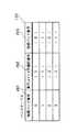
図2は、通信メモリ151のデータ構造を示す図である。
同図に示すように、通信メモリ151の先頭の16バイトはメモリ管理テーブル310として用いられ、その後は16バイト毎に1つのコマンドを格納するためのコマンド用エリアとして用いられている。2キロバイトの通信メモリ中には、同図に示すようにコマンド用エリア(1)から、コマンド用エリア(127)までの127個のコマンドを格納するための領域が設けられている。なお、N番目のコマンド用エリアをここではコマンド用エリア(N)と表現している。
【0030】
以下、何番目のコマンド用エリアであるかを示す7ビットの数値を含む1バイトのデータをコマンドIDという。従って、コマンドIDはコマンドの通信メモリ151内における所在を示すことになる。
メモリ管理テーブル310は、16バイト即ち128ビットで構成され、先頭の0ビット目を除いて、Nビット目はコマンド用エリア(N)の使用状態を示している。使用状態は、例えば1という値で使用中を表し、0という値で空いている即ち新たに使用可能であることを表す。
【0031】
従って、メモリ管理テーブル310の先頭ビットを0ビット目として、その次のビット即ち1ビット目の値が1であればコマンド用エリア(1)が使用中であることを示し、その次のビット即ち2ビット目の値が0であればコマンド用エリア(2)が空いていることを示す。なお、マスタプロセッサ110が通信メモリにコマンドを全く格納していない状態においては、メモリ管理テーブル310の全てのビット値は0である。
【0032】
図3は、コマンド列の一構成要素であり、通信メモリ151に格納されるコマンドのフォーマットを示す図である。
なお、同図では、コマンド200を2バイト毎に区分して、16進数で表した0バイト目からEバイト目という位置201とその意味内容を示す項目202とを対応付けて表現している。
【0033】
コマンドのサイズは16バイトであり、同図に示すように、0バイト目からの2バイトはコマンド種別及び属性を表し、2バイト目からの2バイトは次コマンドIDを含むデータを表し、4バイト目以後からはスレーブハード毎に独自のパラメータ類を表す。
なお、0バイト目からの2バイトであるコマンド種別及び属性においては、先頭の1ビットがコマンドを実行するスレーブハードの種別を示し、具体的には1という値でスレーブプロセッサ用のコマンドであることを、0という値でDMAコントローラ用のコマンドであることを示す。また、2ビット目は未使用で、3ビット目以後の属性ビットの意味はスレーブハードによって異なり、スレーブプロセッサ用のコマンドにおいては、スレーブプロセッサが実行する命令を特定するためのフォーマット番号、コマンドの実行に際して確保されるべきローカルメモリ131についての仮想バンクを示す仮想バンク番号、解放されるべきローカルメモリ131についての仮想バンクを示す仮想バンク番号等を示し、DMAコントローラ用のコマンドにおいては、主メモリ120からローカルメモリ131へか、ローカルメモリ131から主メモリ120へかといったデータ転送の方向、コマンドの実行即ちデータ転送に用いられるローカルメモリ131についての仮想バンクを示す仮想バンク番号、解放されるべきローカルメモリ131についての仮想バンクを示す仮想バンク番号等を示す。
【0034】
コマンドの2バイト目からの2バイトのデータに含まれる次コマンドIDは、そのコマンドが属するコマンド列における次のコマンドの、通信メモリ151内での所在を示すコマンドIDである。
スレーブプロセッサ用のコマンドについてのパラメータ類は、スレーブプロセッサが実行する命令のスレーブプロセッサ130の命令メモリにおける先頭アドレスである2バイトの実行開始アドレスと、命令の実行に必要な各種パラメータとから構成される。
【0035】
また、DMAコントローラ用のコマンドについてのパラメータ類は、主メモリ120についてのアドレス上位2バイト、下位2バイトと、ローカルメモリ131についてのアドレスと、転送すべきデータのサイズと、主メモリ120についてのアドレスの増分値と、ローカルメモリ131についてのアドレスの増分値とから構成される。
【0036】
図4は、コマンドキュー152のデータ構造を示す図である。
同図に示すように、コマンドキュー152は、コマンドIDを16個まで格納できるキューである。
マスタプロセッサ110がコマンドキュー152に各コマンド列を構成するコマンドのうち先頭のコマンドの所在を示すコマンドIDを逐次挿入し、挿入された順に実行制御部160がコマンドIDを取り出して処理することになる。
【0037】
図5は、マスタプロセッサ110により、通信メモリ151に格納された各コマンド、及びコマンドキュー152に挿入されたコマンドIDの内容例を示す図である。
この例では、コマンドキュー152の先頭に位置しているコマンドIDを始点として次コマンドIDによりチェーンが張られたコマンド用エリア(21)、コマンド用エリア(22)、コマンド用エリア(35)及びコマンド用エリア(36)にそれぞれ格納されたコマンドからなる第1のコマンド列と、コマンドキュー152の先頭の次に位置しているコマンドIDを始点として次コマンドIDによりチェーンが張られたコマンド用エリア(47)、コマンド用エリア(48)、コマンド用エリア(49)及びコマンド用エリア(61)にそれぞれ格納されたコマンドからなる第2のコマンド列とを示している。
【0038】
第1のコマンド列は、データ群間に所定の演算αを施行するためのもので、主メモリ120から、ローカルメモリ131内の仮想バンク番号が0で示される領域へのデータ転送を指示するDMAコントローラ用のReadDMAコマンドと、主メモリ120から、ローカルメモリ131内の仮想バンク番号が1で示される領域へのデータ転送を指示するDMAコントローラ用のReadDMAコマンドと、仮想バンク番号が0及び1で示される領域を用いて所定の演算αを行ってその結果を仮想バンク番号が1で示される領域に反映することを指示するスレーブプロセッサ用のSPstartコマンドと、仮想バンク番号が1で示されるローカルメモリ131内の領域から主メモリ120へのデータ転送を指示するDMAコントローラ用のWriteDMAコマンドとをこの順に連結して構成されるコマンド列である。
【0039】
第2のコマンド列は、データ群間に所定の演算βを施行するためのもので、主メモリ120から、ローカルメモリ131内の仮想バンク番号が0で示される領域へのデータ転送を指示するDMAコントローラ用のReadDMAコマンドと、主メモリ120から、ローカルメモリ131内の仮想バンク番号が1で示される領域へのデータ転送を指示するDMAコントローラ用のReadDMAコマンドと、仮想バンク番号が0及び1で示される領域を用いて所定の演算βを行ってその結果を仮想バンク番号が1で示される領域に反映することを指示するスレーブプロセッサ用のSPstartコマンドと、仮想バンク番号が1で示されるローカルメモリ131内の領域から主メモリ120へのデータ転送を指示するDMAコントローラ用のWriteDMAコマンドとをこの順に連結して構成されるコマンド列である。
【0040】
このように、マスタプロセッサ110は、コマンド列を構成する全てのコマンドを通信メモリ151に格納した後にコマンドキュー152にコマンド列の先頭コマンドについてのコマンドIDを挿入することにより、コマンド列の実行をコマンド実行制御装置150に指示することができる。
<1-3.コマンド実行完了通知インタフェース>
以下、マスタプロセッサ110からのコマンド列の指示に基づいてコマンド実行制御装置150がスレーブハードに実行させたコマンドの実行完了という事象を、マスタプロセッサ110に伝達する際に用いる完了テーブル171の内容について、及び完了通知部170とマスタプロセッサ110との間で授受される信号について、図6及び図7を用いて説明する。
【0041】
図6は、完了テーブル171のデータ構造を示す図である。
完了テーブル171は、128ビットで構成され、先頭の0ビット目を除いて、Nビット目はコマンド用エリア(N)に設定されたコマンドの実行が完了したことを1という値で示すものである。即ち、完了テーブル171は、各コマンドについて1という値でコマンドの実行完了を示す完了フラグの集合であると言える。
【0042】
なお、各ビットの初期値は0であり、コマンドの実行が完了した時には完了受付部153により、そのコマンドに対応するビットに1という値が設定される。図7は、マスタプロセッサ110と完了通知部170との間で授受される信号を示す図である。
マスタプロセッサ110は、コマンドの実行完了の通知を要求したい第1コマンドのコマンドIDを指定したコマンドID指定信号を完了通知部170に伝え、また、第1コマンドとは別にコマンドの実行完了の通知を要求したい第2コマンドのコマンドIDを指定したコマンドID指定信号を完了通知部170に伝えることができる。
【0043】
完了通知部170は、伝えられたコマンドIDを第1コマンド及び第2コマンドのコマンドIDを保持し、完了テーブル171において、第1コマンド又は第2コマンドに対応する完了フラグが1に設定された時に、その設定された第1コマンド又は第2コマンドの実行が完了した旨を示す完了通知信号をマスタプロセッサ110に伝える。また、完了通知部170は、第1コマンド又は第2コマンドのコマンドIDが変化した場合において、第1コマンド又は第2コマンドに対応する完了フラグが既に1に設定されていたときには、直ちに完了通知信号をマスタプロセッサ110に伝える。
【0044】
また、マスタプロセッサ110は、完了通知信号を受け取った後に、後の完了フラグの利用のために、第1コマンド又は第2コマンドの完了テーブルにおける完了フラグの値を0にすることを要求する旨の完了フラグクリア要求信号を完了通知部170に伝えることができる。
<1-4.バンクテーブルによるメモリ管理>
以下、コマンド実行制御装置150の実行制御部160が用いるバンクテーブル163について図8を用いて説明する。
【0045】
図8は、バンクテーブル163のデータ構造及び内容例を示す図である。
バンクテーブル163は、同図に示すように、ローカルメモリ131のバンク#0〜#3を特定する0〜3の4つの物理バンク番号について、物理バンク番号261と実行コマンド列識別番号262と仮想バンク番号263とを対応付けたテーブルである。同図中括弧で示した数値は実行制御部160により変更され得る値であることを示している。
【0046】
ここで、実行コマンド列識別番号262は、実行制御部160によって現在実行対象とされている各コマンド列を識別するための番号である。実行制御部160は、あるコマンド列中のコマンドをスレーブハードに実行させ始める時に、そのコマンド列中の次順位のコマンドのコマンドIDを次コマンドID保持部161又は次コマンドID保持部162に格納するので、現在実行対象とされているコマンド列を次コマンドID保持部の識別番号でもって表すことができる。このため、実行コマンド列識別番号262は、次コマンドID保持部の識別番号である1又は2という値で表される。但し、仮想バンク番号が対応付けられていない物理バンク番号についての実行コマンド列識別番号262は、対応付けられていないことを表す値として予め定めた例えば3等の値をとることになる。
【0047】
また、仮想バンク番号263は、コマンド中の属性において指定された仮想バンク番号であって実行制御部160によって物理バンク番号と対応付けられた番号である。なお、仮想バンク番号はコマンドにおいて0〜3のいずれかの指定が可能である。
仮想バンク番号が対応付けられていない物理バンク番号についての仮想バンク番号263は、対応付けられていないことを表すと予め定めた例えば4等の値をとることになる。
【0048】
なお、実行制御部160は、仮想バンク番号と物理バンク番号との対応関係を管理するためにこのバンクテーブル163を用い、あるコマンド列中のコマンドをスレーブハードに実行させる際に、そのコマンド中の属性において確保すべきものとして仮想バンク番号が指定されている場合には、空いている物理バンク番号と、コマンド列における次順位のコマンドの所在を示すコマンドIDを格納することになる次コマンドID保持部の識別番号と、その実行させるコマンド中の属性において指定された仮想バンク番号とを対応付けるようバンクテーブル163の内容を更新する。
【0049】
また、コマンド中の属性において解放すべきものとして仮想バンク番号が指定されている場合には、実行制御部160は、その仮想バンク番号と対応付けられている物理バンク番号についての実行コマンド列識別番号262及び仮想バンク番号263のそれぞれを、対応付けられていないことを示す値として予め定めた例えば3及び4等の値にすべくバンクテーブル163の内容を更新する。
【0050】
この実行制御部160による、確保又は解放すべき仮想バンク番号を含むコマンドに応じたバンクテーブル163の更新は、実際にスレーブハードにコマンドを実行させる直前に行われる。但し、実行制御部160は、仮想バンク番号を指定してメモリ領域の確保を指示するコマンドについては、ローカルメモリ131中の物理バンクのうちに、どの仮想バンク番号とも対応付けられていない物理バンクがある場合に限り、その対応付けられていない物理バンクとコマンドで指定された仮想バンクとを対応付けるようにバンクテーブル163の内容を更新してそのコマンドをスレーブハードに実行開始させる。
【0051】
<1-5.動作>
以下、処理システム100の動作について説明する。
処理システム100において、マスタプロセッサ110は、アプリケーションプログラムその他のプログラムに基づいてコマンド列を随時、上述したコマンド列指定インタフェースによりコマンド実行制御装置150に伝えて必要に応じてコマンド実行制御装置150にコマンドに対応する処理の実行完了の通知を要求しその実行完了を示す通知を受け取る処理(以下、「マスタプロセッサ処理」という。)を実行し、コマンド実行制御装置150は、伝えられたコマンド列に基づいてコマンドをスレーブハードに実行させる処理(以下、「実行制御処理」という。)及び上述したコマンド実行完了通知インタフェースによりコマンドの実行完了をマスタプロセッサに通知する処理を実行する。
【0052】
なお、マスタプロセッサ110がコマンド実行制御装置150に伝えるコマンド列は、予めプログラムによって特定されるものである。
以下、マスタプロセッサ処理及び実行制御処理について、図9〜図11に示すフローチャートに沿って詳細に説明する。
<1-5-1.マスタプロセッサ処理>
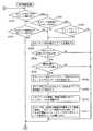
図9は、マスタプロセッサ110によりなされるマスタプロセッサ処理を示すフローチャートである。
【0053】
マスタプロセッサ110は、通信メモリ151中のメモリ管理テーブル310を参照し、空いているコマンド用エリアをサーチし、空いているコマンド用エリアにコマンド列を構成する各コマンドを記録する(ステップS11)。
マスタプロセッサ110は空いているコマンド用エリアのサーチを、例えば、メモリ管理テーブル310のビット位置が1から127までの各ビットを順にチェックしてそのビット値が1でなく0であるところのビット位置を得て、そのビット位置がNであれば、コマンド用エリア(N)を検出結果として得るという手順で行う。
【0054】
例えば、4つのコマンドからなるコマンド列を指定する場面を想定すると、マスタプロセッサ110は上述の手順により4つの空いているコマンド用エリアを検出して、各コマンド用エリアに1つずつコマンドの内容を記録することになる。なお、マスタプロセッサ110は、コマンドを記録する際に16バイトのコマンドの先頭から2バイト目にコマンド列における次順位のコマンドを格納したコマンド用エリアの番号であるコマンドIDを設定する。また、コマンドをコマンド用エリアに記録した際にマスタプロセッサはそのコマンド用エリアに対応するメモリ管理テーブル310中のビット値を0から1に更新する。
【0055】
コマンド用エリアにコマンド列を構成する各コマンドを記録した後に、マスタプロセッサ110は、コマンドの実行完了のタイミングを検出する必要のあるコマンドを格納したコマンド用エリアの番号であるコマンドIDを示すコマンドID指定信号を完了通知部170に伝える(ステップS12)。
続いてマスタプロセッサ110は、コマンド列の先頭のコマンドを格納したコマンド用エリアの番号であるコマンドIDをコマンドキュー152に挿入する(ステップS13)。
【0056】
なお、マスタプロセッサ110が実行するプログラムによっては、マスタプロセッサ110はステップS11において複数のコマンド列それぞれを構成する各コマンドを空いているコマンド用エリアにまとめて記録し、また、ステップS13において複数のコマンドIDをまとめてコマンドキューに挿入する場合もある。また、ステップS12においては2つのコマンドについてコマンドIDを完了通知部に伝える場合もある。
【0057】
ステップS13の後に、マスタプロセッサ110は、実行完了を待つ必要があるコマンドがあればそのコマンドについての完了通知信号が完了通知部170から伝えられるのを待つ(ステップS14)。
ステップS13においてコマンドキュー152に挿入されたコマンドIDに基づいて、コマンド実行制御装置150の実行制御部160はコマンド列を構成する先頭のコマンドを特定し、コマンド内の次コマンドIDを参照して順に次のコマンドを特定して、コマンド列における順番に従ってコマンドをスレーブハードに実行させる制御を行う。
【0058】
従って、このようなステップS11〜S14の手順を、マスタプロセッサ110が繰り返し行うことにより複数のコマンド列を構成する各コマンドがスレーブハードによって実行される。
このステップS11及びS13により、通信メモリ151及びコマンドキュー152は、例えば図5に例示した内容になる。
【0059】
<1-5-2.実行制御処理>
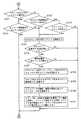
図10は、コマンド実行制御装置150内の実行制御部160によりなされる実行制御処理の一部を示すフローチャートであり、図11は、コマンド実行制御装置150内の実行制御部160によりなされる実行制御処理のうち図10に示した以外の部分を示すフローチャートである。
【0060】
まず、実行制御部160は、1という識別番号で識別される次コマンドID保持部161にコマンドIDが保持されたことのあるコマンド列(以下、「コマンド列#1」という。)中のコマンドをスレーブハードに実行させている状態であるか否か即ちそのコマンドに対応するスレーブハードが稼働状態であるか否かを判定する(ステップS21)。
【0061】
なお、実行制御部160は、コマンドの実行をスレーブハードに指示した後にそのコマンドの所在を示すコマンドIDを図示していない内部の作業用メモリ領域に保持し、そのスレーブハードによるコマンドの実行完了を完了受付部153から伝えられるまでは、コマンドをスレーブハードに実行させている状態であると判定し、コマンドの実行完了を完了受付部153から伝えられた後には、内部の作業用メモリ領域内に保持したそのコマンドについてのコマンドIDを削除して、コマンドをスレーブハードに実行させていない状態であると判定する。内部の作業用メモリ領域には、コマンドの出所であるコマンド列別に各1つのコマンドIDを保持でき、ここに保持されているコマンドIDに対応するコマンド中の先頭ビットによってどのスレーブハードが現在稼働中であるかを実行制御部160は検知することができる。
【0062】
ステップS21において、コマンド列#1中のコマンドに対応するスレーブハードが稼働状態でないと判定した場合に、実行制御部160は、次コマンドID保持部161に保持されているコマンドIDは0以外か否かを判定し(ステップS22)、そのコマンドIDが0であれば、コマンドキュー152にコマンドIDが格納されているか否かを判定する(ステップS23)。
【0063】
ステップS22において次コマンドID保持部161に保持されているコマンドIDが0以外であると判定した場合には、実行制御部160は、次コマンドID保持部161に保持されているコマンドIDの示すコマンド用エリアに格納されているコマンドに着目し、そのコマンドを解読する(ステップS24)。
また、ステップS23においてコマンドキュー152にコマンドIDが格納されていると判定した場合には、実行制御部160は、コマンドキュー152の先頭のコマンドIDの示すコマンド用エリアに格納されているコマンドに着目し、そのコマンドを解読する(ステップS24)。
【0064】
ステップS24に続いて、実行制御部160は、コマンド中の属性に確保すべき仮想バンク番号の指定が含まれている場合において、バンクテーブル163を参照して、その仮想バンク番号と対応付けることのできる物理バンク番号が空いているかを、即ちローカルメモリ131のバンクが不足することがないかを調べ(ステップS25)、バンクが不足しないと判定した場合には、内部の作業用メモリ領域を参照することにより、そのコマンドを実行するスレーブハードは空いている即ち非稼働状態であるか否かを判定する(ステップS26)。
【0065】
ステップS26においてそのコマンドを実行するスレーブハードが非稼働状態であると判定した場合には、実行制御部160は、ステップS23を経由してステップS24においてコマンドキュー152中のコマンドIDが示すコマンドに着目しているときに限りコマンドキュー152からそのコマンドIDを消去する(ステップS27)。なお、ステップS22において次コマンドID保持部161に保持されているコマンドIDが0以外であった場合には実行制御部160はステップS27の処理を省略する。
【0066】
続いて、実行制御部160は、解読したコマンド内に示される次コマンドIDを次コマンドID保持部161に格納し(ステップS28)、そのコマンド内の属性により確保すべきと指定された仮想バンク番号があれば、その仮想バンク番号と空いている物理バンク番号とを対応付け、バンクテーブル163を更新する(ステップS29)。なお、仮想バンク番号と物理バンク番号とが既に対応付けられている場合においては実行制御部160はステップS29を省略する。更に、コマンド内の属性により解放すべきと指定された仮想バンク番号があれば、実行制御部160はその仮想バンク番号と対応付けられている物理バンク番号を空きの状態となるようにバンクテーブル163を更新する。
【0067】
ステップS29に続いて、実行制御部160は、コマンドの先頭ビットで指定されたスレーブハード、即ちスレーブプロセッサ130又はDMAコントローラ140にコマンドの実行を指示し、そのコマンドを示すコマンドIDを内部の作業用メモリ領域に設定する(ステップS30)。実行指示にあたり、実行制御部160は、コマンド内で指定された仮想バンク番号と対応付けた物理バンク番号をスレーブハードに伝え、これを受けてスレーブハードは物理バンク番号で特定されるローカルメモリ131中のバンクを処理対象としてコマンドの実行を行う。なお、後にスレーブプロセッサ130又はDMAコントローラ140から完了受付部153にコマンドの実行完了が伝えられた時に、完了受付部153からその旨を伝えられて実行制御部160は内部の作業用メモリ領域から実行が完了したコマンドのコマンドIDを消去する。
【0068】
ステップS30における実行制御部160によるスレーブハードへのコマンドの実行の指示は、例えば次のように行われる。即ち、実行制御部160は、解読したコマンドの中でスレーブハードに必要なデータを抽出して、つまり属性と実行ハード別のパラメータ類を抽出して、その抽出したデータのうち仮想バンク番号についてはバンクテーブル163により対応付けられている物理バンク番号に置き換え、その結果のデータをコマンドの実行対象となるスレーブプロセッサ130又はDMAコントローラ140に送信することにより行われる。
【0069】
ステップS30の後、或いは、ステップS21においてコマンド列#1中のコマンドに対応するスレーブハードが稼働状態であると判定した後、ステップS23においてコマンドキュー152にコマンドIDが格納されていないと判定した後、ステップS25においてローカルメモリ131のバンクが不足していると判定した後又はステップS26においてコマンドを実行するスレーブハードが空いていないと判定した後には、実行制御部160は、2という識別番号で識別される次コマンドID保持部162にコマンドIDが保持されたことのあるコマンド列(以下、「コマンド列#2」という。)中のコマンドをスレーブハードに実行させている状態であるか否か即ちそのコマンドに対応するスレーブハードが稼働状態であるか否かを判定する(ステップS31)。
【0070】
ステップS31において、コマンド列#2中のコマンドに対応するスレーブハードが稼働状態でないと判定した場合に、実行制御部160は、次コマンドID保持部162に保持されているコマンドIDは0以外か否かを判定し(ステップS32)、そのコマンドIDが0であれば、コマンドキュー152にコマンドIDが格納されているか否かを判定する(ステップS33)。
【0071】
ステップS32において次コマンドID保持部162に保持されているコマンドIDが0以外であると判定した場合には、実行制御部160は、次コマンドID保持部162に保持されているコマンドIDの示すコマンド用エリアに格納されているコマンドに着目し、そのコマンドを解読する(ステップS34)。
また、ステップS33においてコマンドキュー152にコマンドIDが格納されていると判定した場合には、実行制御部160は、コマンドキュー152の先頭のコマンドIDの示すコマンド用エリアに格納されているコマンドに着目し、そのコマンドを解読する(ステップS34)。
【0072】
ステップS34に続いて、実行制御部160は、コマンド中の属性に確保すべき仮想バンク番号の指定が含まれている場合において、バンクテーブル163を参照して、その仮想バンク番号と対応付けるためにローカルメモリ131のバンクが不足することがないかを調べ(ステップS35)、バンクが不足しないと判定した場合には、内部の作業用メモリ領域を参照することにより、そのコマンドを実行するスレーブハードが非稼働状態であるか否かを判定する(ステップS36)。
【0073】
ステップS36においてそのコマンドを実行するスレーブハードが非稼働状態であると判定した場合には、実行制御部160は、ステップS33を経由してステップS34においてコマンドキュー152中のコマンドIDが示すコマンドに着目しているときに限りコマンドキュー152からそのコマンドIDを消去する(ステップS37)。なお、ステップS32において次コマンドID保持部162に保持されているコマンドIDが0以外であった場合には実行制御部160はステップS37の処理を省略する。
【0074】
続いて、実行制御部160は、解読したコマンド内に示される次コマンドIDを次コマンドID保持部162に格納し(ステップS38)、そのコマンド内の属性により確保すべきと指定された仮想バンク番号があれば、その仮想バンク番号と空いている物理バンク番号とを対応付け、バンクテーブル163を更新する(ステップS39)。なお、仮想バンク番号と物理バンク番号とが既に対応付けられている場合においては実行制御部160はステップS39を省略する。更に、コマンド内の属性により解放すべきと指定された仮想バンク番号があれば、実行制御部160はその仮想バンク番号と対応付けられている物理バンク番号を空きの状態となるようにバンクテーブル163を更新する。
【0075】
ステップS39に続いて、実行制御部160は、コマンドの先頭ビットで指定されたスレーブプロセッサ130又はDMAコントローラ140にコマンドの実行を指示し、そのコマンドを示すコマンドIDを内部の作業用メモリ領域に設定する(ステップS40)。ステップS30においてと同様に実行指示にあたり、実行制御部160は、コマンド内で指定された仮想バンク番号と対応付けた物理バンク番号をスレーブハードに伝え、これを受けてスレーブハードは物理バンク番号で特定されるローカルメモリ131中の領域を処理対象としてコマンドの実行を行う。なお、後にスレーブプロセッサ130又はDMAコントローラ140から完了受付部153にコマンドの実行完了が伝えられた時に、完了受付部153からその旨を伝えられて実行制御部160は内部の作業用メモリ領域から実行が完了したコマンドのコマンドIDを消去する。
【0076】
ステップS40における実行制御部160によるスレーブハードへのコマンドの実行の指示も具体的には上述したステップS30においてと同様に、コマンド中の属性及び実行ハード別のパラメータ類からなるデータを抽出して、仮想バンク番号を物理バンク番号に置き換えた後に、そのデータをスレーブハードに送信することにより行われる。
【0077】
ステップS40の後、ステップS31においてコマンド列#2中のコマンドに対応するスレーブハードが稼働状態であると判定した後、ステップS33においてコマンドキュー152にコマンドIDが格納されていないと判定した後、ステップS35においてローカルメモリ131のバンクが不足していると判定した後、及びステップS36においてコマンドを実行するスレーブハードが空いていないと判定した後には、実行制御部160は、ステップS21に戻って、1という識別番号で識別される次コマンドID保持部161にコマンドIDが保持されたことのあるコマンド列#1中のコマンドをスレーブハードに実行させている状態であるか否か即ちそのコマンドに対応するスレーブハードが稼働状態であるか否かを判定する処理を行う(ステップS21)。
【0078】
こうして、実行制御部160はステップS21〜S40の実行制御処理を繰り返し行う。
<1-5-3.実行制御部の動作例>
以下、通信メモリ151及びコマンドキュー152が、図5に例示した内容になっていることを前提として、実行制御部160の具体的動作を説明する。
【0079】
まず、初期状態において実行制御部160内部の作業メモリにはコマンドIDが格納されていおらず、次コマンドID保持部161及び次コマンドID保持部162はコマンドIDを保持していない旨を示す値0を格納しており、バンクテーブル163においては各物理バンク番号はまだ仮想バンク番号と対応付けられていない。
【0080】
従って、実行制御部160は、ステップS21においてコマンド列#1中のコマンドは実行中でないと判定してnoの分岐に進み(図10参照)、ステップS22において次コマンドID保持部161に保持されているコマンドIDが0であると判定してnoの分岐に進み、コマンドキュー152内にコマンドIDがあるか否かを判定する(ステップS23)。
【0081】
コマンドキュー152には図5に示すようにコマンドIDが格納されているので、実行制御部160はそのコマンドキュー152の先頭の「21」という値のコマンドIDで示されるコマンド用エリア(21)内に格納されているDMAコントローラ用のReadDMAコマンドに着目し、そのReadDMAコマンドを解読する(ステップS24)。
【0082】
ステップS24で解読したReadDMAコマンドは仮想バンク番号が0の仮想バンクを確保することを要するものであるから、実行制御部160は物理バンク番号のうち仮想バンク番号と対応付けられていないものがあるかバンクテーブル163を参照してチェックし(ステップS25)、対応付けられていないものがあるのでステップS25においてyesの分岐に進み、DMAコントローラが非稼働状態であるか否かを判定して(ステップS26)、非稼働状態であるためステップS26においてyesの分岐に進み、コマンドキュー152から値が「21」であるコマンドIDを消去するとともに(ステップS27)、ReadDMAコマンド内における次コマンドIDの値である「22」を次コマンドID保持部161に格納する(ステップS28)。
【0083】
ステップS28に続いて実行制御部160は、バンクテーブル163を参照して、空いている物理バンク番号を検出し、解読したReadDMAコマンドで指定されていた0という仮想バンク番号に空いている0という物理バンク番号とを対応付けて、バンクテーブル163を更新する(ステップS29)。この結果、バンクテーブル163は、物理バンク番号が0のバンクについて、実行コマンド列識別番号が1で、仮想バンク番号が0という情報を対応付けた内容となる。
【0084】
ステップS29の後、実行制御部160は、解読したReadDMAコマンドをDMAコントローラ140に伝えて、コマンドの実行を要求する(ステップS30)。即ち、実行制御部160は、主メモリアドレス、0という物理バンク番号、ローカルメモリアドレス、転送サイズ、主メモリアドレス増分、ローカルメモリアドレス増分、及び主メモリからローカルメモリへのデータ転送である旨を示すデータをDMAコントローラ140に送信する。
【0085】
これによって、DMAコントローラ140は、主メモリ120からローカルメモリ131のバンク#0へのデータ転送を開始する。なお、実行制御部160は、そのReadDMAコマンドのコマンドIDを内部の作業用メモリ領域に保持する。
次に、実行制御部160は、ステップS31においてコマンド列#2中のコマンドは実行中でないと判定してnoの分岐に進み(図11参照)、ステップS32において次コマンドID保持部162に保持されているコマンドIDが0であると判定してnoの分岐に進み、コマンドキュー152内にコマンドIDがあるか否かを判定する(ステップS33)。
【0086】
コマンドキュー152には、先のステップS27により値が「21」であるコマンドIDは消去されているがまだ値が「47」であるコマンドIDは残っているので(図5参照)、実行制御部160はそのコマンドキュー152の先頭の「47」という値のコマンドIDで示されるコマンド用エリア(47)内に格納されているDMAコントローラ用のReadDMAコマンドに着目し、そのReadDMAコマンドを解読する(ステップS34)。
【0087】
ステップS34で解読したReadDMAコマンドは仮想バンク番号が0の仮想バンクを確保することを要するものであるから、実行制御部160は物理バンク番号のうち仮想バンク番号と対応付けられていないものがあるかバンクテーブル163を参照してチェックし(ステップS35)、対応付けられていないものがあるのでステップS35においてyesの分岐に進み、DMAコントローラが非稼働状態であるか否かを判定して(ステップS36)、DMAコントローラ140は先行するReadDMAコマンドの実行中であり稼働状態であるためステップS36においてnoの分岐に進み、ステップS21の判定に戻る。
【0088】
ここでは、その後、DMAコントローラ140がコマンド用エリア(21)に格納されていたReadDMAコマンドの実行を完了したこととして説明を続ける。なお、DMAコントローラ140は実行の完了を完了受付部153に伝え、実行制御部160は完了受付部153からの完了の通知を受けて内部の作業用メモリ領域からDMAコントローラ用コマンドのコマンドIDを削除する。
【0089】
実行制御部160は、ステップS21において、作業用メモリ領域からコマンドIDが削除されているのでコマンド列#1中のコマンドは実行中でないと判定してnoの分岐に進み、ステップS22において次コマンドID保持部161に保持されているコマンドIDが「22」であると判定してyesの分岐に進み、コマンド用エリア(22)内に格納されているDMAコントローラ用のReadDMAコマンドに着目し、そのReadDMAコマンドを解読する(ステップS24)。
【0090】
ステップS24で解読したReadDMAコマンドは仮想バンク番号が1の仮想バンクを確保することを要するものであるから、実行制御部160は物理バンク番号のうち仮想バンク番号と対応付けられていないものがあるかバンクテーブル163を参照してチェックし(ステップS25)、対応付けられていないものがあるのでステップS25においてyesの分岐に進み、DMAコントローラが非稼働状態であるか否かを判定して(ステップS26)、非稼働状態であるためステップS26においてyesの分岐に進み、ReadDMAコマンド内における次コマンドIDの値である「35」を次コマンドID保持部161に格納する(ステップS28)。
【0091】
ステップS28に続いて実行制御部160は、バンクテーブル163を参照して、空いている物理バンク番号を検出し、解読したReadDMAコマンドで指定されていた0という仮想バンク番号に空いている1という物理バンク番号とを対応付けて、バンクテーブル163を更新する(ステップS29)。この結果、バンクテーブル163は、物理バンク番号が1のバンクについて、実行コマンド列識別番号が1で、仮想バンク番号が1という情報を対応付けた内容となる。
【0092】
ステップS29の後、実行制御部160は、解読したReadDMAコマンドをDMAコントローラ140に伝えて、コマンドの実行を要求する(ステップS30)。即ち、実行制御部160は、主メモリアドレス、1という物理バンク番号、ローカルメモリアドレス、転送サイズ、主メモリアドレス増分、ローカルメモリアドレス増分、及び主メモリからローカルメモリへのデータ転送である旨を示すデータをDMAコントローラ140に送信する。これによって、DMAコントローラ140は、主メモリ120からローカルメモリ131のバンク#1へのデータ転送を開始する。
【0093】
ここでは、その後、DMAコントローラ140がコマンド用エリア(22)に格納されていたReadDMAコマンドの実行を完了したこととして、ステップS21から説明を続ける。
実行制御部160は、ステップS21においてコマンド列#1中のコマンドは実行中でないと判定してnoの分岐に進み、ステップS22において次コマンドID保持部161に保持されているコマンドIDが「35」であると判定してyesの分岐に進み、コマンド用エリア(35)内に格納されているスレーブプロセッサ用のSPstartコマンドに着目し、そのSPstartコマンドを解読する(ステップS24)。
【0094】
ステップS24で解読したSPstartコマンドは仮想バンク番号が0及び1の仮想バンクを確保することを要するものであるが、既にバンクテーブル163において0及び1という仮想バンク番号はそれぞれ0、1という物理バンク番号と対応付けられており、バンク不足は生じないため、実行制御部160は、ステップS25においてyesの分岐に進み、スレーブプロセッサが非稼働状態であるか否かを判定して(ステップS26)、非稼働状態であるためステップS26においてyesの分岐に進み、SPstartコマンド内における次コマンドIDの値である「36」を次コマンドID保持部161に格納する(ステップS28)。
【0095】
ステップS28に続いて実行制御部160は、仮想バンク番号と物理バンク番号との対応付けは既に行われているためステップS29を省き、解読したSPstartコマンドをスレーブプロセッサ130に伝えて、コマンドの実行を要求する(ステップS30)。即ち、実行制御部160は、命令を特定するためのフォーマット番号、0及び1という物理バンク番号、スレーブプロセッサ130の命令メモリにおける実行開始アドレス、及びパラメータ1〜5を示すデータをスレーブプロセッサ130に送信する。これによって、スレーブプロセッサ130は、ローカルメモリ131のバンク#0とバンク#1の内容に基づいて演算αを行ってその結果をバンク#1に書き込む処理を開始する。
【0096】
次に、実行制御部160は、ステップS31においてコマンド列#2中のコマンドは実行中でないと判定してnoの分岐に進み、ステップS32において次コマンドID保持部162に保持されているコマンドIDが0であると判定してnoの分岐に進み、コマンドキュー152内にコマンドIDがあるか否かを判定する(ステップS33)。
【0097】
コマンドキュー152には、「47」という値のコマンドIDで示されるコマンド用エリア(47)内に格納されているDMAコントローラ用のReadDMAコマンドに着目し、そのReadDMAコマンドを解読する(ステップS34)。
ステップS34で解読したReadDMAコマンドは仮想バンク番号が0の仮想バンクを確保することを要するものであるから、実行制御部160は物理バンク番号のうち仮想バンク番号と対応付けられていないものがあるかバンクテーブル163を参照してチェックし(ステップS35)、対応付けられていないものがあるのでステップS35においてyesの分岐に進み、DMAコントローラが非稼働状態であるか否かを判定して(ステップS36)、DMAコントローラ140は既に非稼働状態であるためステップS36においてyesの分岐に進み、コマンドキュー152から値が「47」であるコマンドIDを消去するとともに(ステップS37)、ReadDMAコマンド内における次コマンドIDの値である「48」を次コマンドID保持部162に格納する(ステップS38)。
【0098】
ステップS38に続いて実行制御部160は、バンクテーブル163を参照して、空いている物理バンク番号を検出し、解読したReadDMAコマンドで指定されていた0という仮想バンク番号に空いている2という物理バンク番号とを対応付けて、バンクテーブル163を更新する(ステップS39)。この結果、バンクテーブル163は、物理バンク番号が2のバンクについて、実行コマンド列識別番号が2で、仮想バンク番号が0という情報を対応付けた内容となる。
【0099】
ステップS39の後、実行制御部160は、解読したReadDMAコマンドをDMAコントローラ140に伝えて、コマンドの実行を要求する(ステップS40)。即ち、実行制御部160は、主メモリアドレス、2という物理バンク番号、ローカルメモリアドレス、転送サイズ、主メモリアドレス増分、ローカルメモリアドレス増分、及び主メモリからローカルメモリへのデータ転送である旨を示すデータをDMAコントローラ140に送信する。これによって、DMAコントローラ140は、主メモリ120からローカルメモリ131のバンク#2へのデータ転送を開始する。
【0100】
ここでは、その後、スレーブプロセッサ130がコマンド用エリア(35)に格納されていたSPstartコマンドの実行を継続している間に、DMAコントローラ140がコマンド用エリア(47)に格納されていたReadDMAコマンドの実行を完了したこととして、ステップS21から説明を続ける。
実行制御部160は、ステップS21においてコマンド列#1中のコマンドがまだ実行中であると判定してyesの分岐に進み、ステップS31においてコマンド列#2中のコマンドは実行中でないと判定してnoの分岐に進み、ステップS32において次コマンドID保持部162に保持されているコマンドIDが「48」であると判定してyesの分岐に進み、コマンド用エリア(48)内に格納されているDMAコントローラ用のReadDMAコマンドに着目し、そのReadDMAコマンドを解読する(ステップS34)。
【0101】
ステップS34で解読したReadDMAコマンドは仮想バンク番号が1の仮想バンクを確保することを要するものであるから、実行制御部160は物理バンク番号のうち仮想バンク番号と対応付けられていないものがあるかバンクテーブル163を参照してチェックし(ステップS35)、対応付けられていないものがあるのでステップS35においてyesの分岐に進み、DMAコントローラが非稼働状態であるか否かを判定して(ステップS36)、DMAコントローラ140は既に非稼働状態であるためステップS36においてyesの分岐に進み、ReadDMAコマンド内における次コマンドIDの値である「49」を次コマンドID保持部162に格納する(ステップS38)。
【0102】
ステップS38に続いて実行制御部160は、バンクテーブル163を参照して、空いている物理バンク番号を検出し、解読したReadDMAコマンドで指定されていた1という仮想バンク番号に空いている3という物理バンク番号とを対応付けて、バンクテーブル163を更新する(ステップS39)。この結果、バンクテーブル163は、物理バンク番号が3のバンクについて、実行コマンド列識別番号が2で、仮想バンク番号が1という情報を対応付けた内容となる。
【0103】
従って、この時点でバンクテーブル163の内容は図8に例示した状態となる。
ステップS39の後、実行制御部160は、解読したReadDMAコマンドをDMAコントローラ140に伝えて、コマンドの実行を要求する(ステップS40)。即ち、実行制御部160は、主メモリアドレス、3という物理バンク番号、ローカルメモリアドレス、転送サイズ、主メモリアドレス増分、ローカルメモリアドレス増分、及び主メモリからローカルメモリへのデータ転送である旨を示すデータをDMAコントローラ140に送信する。これによって、DMAコントローラ140は、主メモリ120からローカルメモリ131のバンク#3へのデータ転送を開始する。
【0104】
この後、スレーブプロセッサ130がコマンド用エリア(35)に格納されていたSPstartコマンドの実行を完了し、また、DMAコントローラ140がコマンド用エリア(48)に格納されていたReadDMAコマンドの実行を完了したとして、ステップS21から説明を続ける。
実行制御部160は、ステップS21においてコマンド列#1中のコマンドは実行中でないと判定してnoの分岐に進み、ステップS22において次コマンドID保持部161に保持されているコマンドIDが「36」であると判定してyesの分岐に進み、コマンド用エリア(36)内に格納されているDMAコントローラ用のWriteDMAコマンドに着目し、そのWriteDMAコマンドを解読する(ステップS24)。
【0105】
ステップS24で解読したWriteDMAコマンドは仮想バンク番号が1の仮想バンクを確保することを要するものであるが、既にバンクテーブル163において1という仮想バンク番号は1という物理バンク番号と対応付けられており、バンク不足は生じないため、実行制御部160は、ステップS25においてyesの分岐に進み、DMAコントローラが非稼働状態であるか否かを判定して(ステップS26)、非稼働状態であるためステップS26においてyesの分岐に進み、WriteDMAコマンド内における次コマンドIDの値である「0」を次コマンドID保持部161に格納する(ステップS28)。
【0106】
ステップS28に続いて実行制御部160は、仮想バンク番号と物理バンク番号との対応付けは既に行われているためステップS29を省き、解読したWriteDMAコマンドをDMAコントローラ140に伝えて、コマンドの実行を要求する(ステップS30)。即ち、実行制御部160は、主メモリアドレス、1という物理バンク番号、ローカルメモリアドレス、転送サイズ、主メモリアドレス増分、ローカルメモリアドレス増分、及びローカルメモリから主メモリへのデータ転送である旨を示すデータをDMAコントローラ140に送信する。これによって、DMAコントローラ140は、ローカルメモリ131のバンク#1から主メモリ120へのデータ転送を開始する。
【0107】
なお、WriteDMAコマンド内で、0という仮想バンク番号についての解放が指定されていた場合には、ステップS29のタイミングで実行制御部160は、0という物理バンク番号が空いている旨を示すようにバンクテーブル163を更新する。
次に、実行制御部160は、ステップS31においてコマンド列#2中のコマンドは実行中でないと判定してnoの分岐に進み、ステップS32において次コマンドID保持部162に保持されているコマンドIDが「49」であると判定してyesの分岐に進み、コマンド用エリア(49)内に格納されているスレーブプロセッサ用のSPstartコマンドに着目し、そのSPstartコマンドを解読する(ステップS34)。
【0108】
ステップS34で解読したSPstartコマンドは仮想バンク番号が0及び1の仮想バンクを確保することを要するものであるが、既にバンクテーブル163において0及び1という仮想バンク番号はそれぞれ2、3という物理バンク番号と対応付けられており、バンク不足は生じないため、実行制御部160は、ステップS35においてyesの分岐に進み、スレーブプロセッサが非稼働状態であるか否かを判定して(ステップS36)、非稼働状態であるためステップS36においてyesの分岐に進み、SPstartコマンド内における次コマンドIDの値である「61」を次コマンドID保持部161に格納する(ステップS38)。
【0109】
ステップS38に続いて実行制御部160は、仮想バンク番号と物理バンク番号との対応付けは既に行われているためステップS39を省き、解読したSPstartコマンドをスレーブプロセッサ130に伝えて、コマンドの実行を要求する(ステップS40)。即ち、実行制御部160は、命令を特定するためのフォーマット番号、2及び3という物理バンク番号、スレーブプロセッサ130の命令メモリにおける実行開始アドレス、及びパラメータ1〜5を示すデータをスレーブプロセッサ130に送信する。これによって、スレーブプロセッサ130は、ローカルメモリ131のバンク#2とバンク#3の内容に基づいて演算βを行ってその結果をバンク#3に書き込む処理を開始する。
【0110】
このようにして、実行制御部160は、各コマンド列内での順序に従って各コマンドをスレーブハードに実行させ、より詳しくは、一方のスレーブハードにあるコマンド列のコマンドを実行させている間においても他方のスレーブハードに他のコマンド列のコマンドを並行して実行させ得るので、1つのコマンド列ずつ順番に実行する方式と比べて、スレーブハードを有効活用でき、結果的に高速に複数のコマンド列を実行することができる。
【0111】
<1-6.考察>
図12は、通信メモリ151及びコマンドキュー152が図5に例示した内容であることを前提として、実行制御部160が上述のように動作した場合の各コマンドの実行状況の変化を示すタイムチャートである。
同図では、通信メモリ151のコマンド用エリア(21)に格納されたコマンドを先頭とするコマンド列を「A1」で表し、コマンド用エリア(47)に格納されたコマンドを先頭とするコマンド列を「A2」で表している。
【0112】
仮にコマンド列「A1」の全てのコマンドを順次スレーブハードに実行させた後にコマンド列「A2」の全てのコマンドを順次スレーブハードに実行させることとした場合を想定したならば、SPstartコマンドがスレーブプロセッサ130に実行されている間には、DMAコントローラ140が非稼働状態となってしまう。
【0113】
ところが本実施の形態で示したコマンド実行制御装置150の制御により、実際は、図12に示すように、コマンド列「A1」のSPstartコマンドがスレーブプロセッサ130に実行されている間にも、コマンド列「A2」のReadDMAコマンドがDMAコントローラ140に実行されるため、各スレーブハードの稼働率が高まり、複数のコマンド列全体として見れば処理が高速に行われるようになる。
【0114】
また、コマンド列「A1」を構成するコマンドの実行に際しては、ローカルメモリ131のバンク#0及びバンク#1が用いられ、またコマンド列「A2」を構成するコマンドの実行に際しては、ローカルメモリ131のバンク#2及びバンク#3が用いられ、コマンド列間で独立したメモリ空間を利用して処理が行われるため、データの不整合等が生じないことが保証される。
<実施の形態2>
実施の形態1で示した処理システム100においては、実行制御部160は、ある仮想バンク番号を指定してメモリ領域の確保を指示する属性を含むコマンドについて、その仮想バンクに1つの空いている物理バンク番号を、バンクテーブル163を用いて対応付ける方式により、各コマンド列間で独立したメモリ空間を利用してスレーブハードに各コマンドの処理を行わせることとした。
【0115】
これに対し実施の形態2に係る処理システムは、実施の形態1に係る処理システム100をわずかに変形した処理システム(以下、「変形処理システム」という。)であり、この変形処理システムは、処理システム100の実行制御部160を変形したものである変形実行制御部がコマンド列間で共通のメモリ領域を利用してスレーブハードに各コマンドの処理を行わせ得る点に特徴がある。
【0116】
<2-1.変形処理システム>
以下、実施の形態2に係る変形処理システムについて説明する。
変形処理システムの構成は基本的に図1に示した処理システム100の構成と一部のみ異なる。従って、変形処理システムの構成要素についても、基本的には図1に示した符号を用いて説明する。
【0117】
変形処理システムが処理システム100と異なる点は、次の通りである。
(1)処理システム100においては、マスタプロセッサ110から通信メモリ151に格納されるコマンドの属性に、仮想バンク番号の指定を伴ってメモリ領域の確保又は解放の指示を含ませることができた。
変形処理システムにおいてはマスタプロセッサ110から通信メモリ151に格納されるコマンドの属性として、上述の仮想バンク番号の指定と確保又は解放の指示とに加えて、その確保又は解放の対象となるメモリ領域がコマンド列間で共通に用いられるべきであることを指定するか否かを示すグローバル属性を、コマンドの属性に付加した点に特徴がある。
【0118】
即ち、コマンドフォーマットにおけるコマンドの属性中の、仮想バンク番号の指定毎に1ビットのグローバル属性の指定が含まれる。以下、コマンド列間で共通にメモリ領域を用いられるべきであることを指定することを、グローバル指定という。
(2)処理システム100においては、バンクテーブル163において、各物理バンク番号261を、実行コマンド列識別番号262及び仮想バンク番号263と対応付けて管理しており、実行コマンド列識別番号262の値は、コマンド列#1とコマンド列#2とのいずれかを示す値、つまり1又は2をとるか、いずれにも対応付けられていないことを示す3等の値をとることとした(図8参照)。
【0119】
図13は、実施の形態2に係る変形処理システムにおけるバンクテーブルの構成及び内容例を示す図である。
変形処理システムにおけるバンクテーブル563は、処理システム100におけるバンクテーブル163と基本的に同様な構成であり、各物理バンク番号564に、実行コマンド列識別番号565及び仮想バンク番号563を対応付けたものであるが、実行コマンド列識別番号565の値が、グローバル指定に対応していずれのコマンド列にも共通する意味を示す値として0をとり得る点のみが相違する。
【0120】
図13の例では、0という物理バンク番号で特定されるローカルメモリ131のバンク#0は、コマンド列間で共通に用いられ、0という仮想バンク番号と対応付けられていることを示しており、またバンク#1はコマンド列#1における仮想バンク番号1と対応付けられており、バンク#2はコマンド列#2における仮想バンク番号1と対応付けられており、バンク#3は空き状態であることを示している。
(3)処理システム100においては、図10及び図11のフローチャートに即して実施の形態1で説明したように、実行制御部160は、コマンド中の属性に、確保すべきメモリ領域を指定する仮想バンク番号が含まれている場合において、バンクテーブル163を参照して、その仮想バンク番号と対応付けることのできる物理バンク番号が空いているかを、即ちローカルメモリ131のバンクが不足することがないかを調べ(ステップS25、S35)、不足しない場合に限りコマンドを実行することとし、コマンド内の属性に応じてメモリ領域の確保又は解放のためにバンクテーブル163を更新し、メモリ領域の確保をすべき旨の属性を含むコマンドをスレーブハードに実行させる際には、コマンドで指定された仮想バンク番号と対応付けた物理バンク番号をスレーブハードに伝えて(ステップS29、S39)、そのスレーブハードがその物理バンク番号で特定されるメモリ領域を処理対象等として用いることができるようにした。
【0121】
変形処理システムにおいても、変形実行制御部が基本的には図10及び図11のフローチャートで示した手順で処理を行う。但し、変形処理システムにおいては、仮想バンク番号を指定しグローバル指定付きでメモリ領域を確保すべき旨の属性が含まれるコマンドについては、バンクテーブルを参照し、指定された仮想バンク番号と0という値の実行コマンド列識別番号との組に対して、既に対応付けられている物理バンク番号が存在すれば、そのコマンドをスレーブハードに実行させる際に、その物理バンク番号をスレーブハードに伝え、また、その対応付けられている物理バンク番号が存在しなければ、空いている物理バンク番号がないかを調べ(ステップS25、S35)、空いている物理バンク番号がある場合に限りコマンドを実行することとし、その空いている物理バンク番号と、0という値の実行コマンド列識別番号と、指定された仮想バンク番号とを対応付けるべくバンクテーブル563を更新し、スレーブハードにその物理バンク番号を伝えて(ステップS29、S39)、そのスレーブハードがその物理バンク番号で特定されるメモリ領域を処理対象等として用いることができるようにする。
【0122】
<2-2.考察>
以上説明したような変形処理システムによれば、一のコマンド列においてグローバル指定で例えば0番の仮想バンク番号でメモリ領域を確保し、そのメモリ領域にスレーブハードによりデータを書き込んでおき、その後においては、他のコマンド列であっても、その0番の仮想バンク番号でメモリ領域を確保する指定のコマンドを置けば、互いに異なるコマンド列に属するコマンドを実行する各スレーブハードが、同一のメモリ領域を用いてコマンドの処理を行うことができるようになる。
【0123】
即ち、各コマンド列間でメモリ領域を共用する処理が構築できるため、この変形処理システムは、同じデータを参照する点を除いて互いに独立した複数の処理を行う必要がある場合に有用となる。
<実施の形態3>
実施の形態1で示した処理システム100においては、実行制御部160は、ある仮想バンク番号を指定してメモリ領域の確保を指示する属性を含むコマンドについて、その仮想バンクに1つの空いている物理バンク番号を、バンクテーブル163を用いて対応付けて、コマンドを実行すべきスレーブハードにその物理バンク番号を伝えて、スレーブハードにその物理バンク番号で特定されるメモリ領域を用いた処理を行わせることとし、また、ある仮想バンク番号を指定してメモリ領域の解放を指示する属性を含むコマンドをスレーブハードに実行させる際にはその実行前に、その仮想バンク番号と対応付けられていた物理バンク番号を空き状態とすべくバンクテーブル163を更新することとしていた。また、処理システム100においては、別個のコマンド列を構成するコマンドが、各スレーブハードによって同時に実行され得るが、一のコマンド列を構成する連続する複数のコマンドは、同時に実行されることなく、コマンドは1つずついずれかのスレーブハードで実行されるようになっていた。
【0124】
これに対し実施の形態3に係る処理システムは、実施の形態1に係る処理システム100を変形した処理システムであり、コマンドの属性によってメモリ領域に確保又は解放を行うことができるのみならず、コマンドを実行中であるスレーブハードからの指示によってメモリ領域の確保、解放等を行うことができるようにした点と、一のコマンド列を構成する連続する複数のコマンドについても、各スレーブハードによって同時に実行され得るようにした点とに特徴がある。但し、実施の形態3に係る処理システムにおいても、一のコマンド列を構成するコマンドは、そのコマンド列の順に従って、いずれかのスレーブハードによって実行開始される点は、処理システム100の場合と同じである。つまり、実施の形態3に係る処理システムにおいては、同一コマンド列内の各コマンドについての各スレーブハードによる実行期間の始期は、必ずコマンド列に従った順序となるが、各コマンドの実行期間は重複し得るし、各コマンドの実行期間の終期はいかなる順序ともなり得る。
【0125】
<3-1.構成>
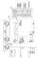
図14は、実施の形態3に係る処理システム600の構成図である。
処理システム600は、同図に示すようにマスタプロセッサ110、主メモリ620、スレーブプロセッサ630、ローカルメモリ131、DMAコントローラ640及びコマンド実行制御装置650を備え、半導体の1チップ内に形成されている。なお、処理システム600の構成要素のうち、処理システム100(図1参照)の構成要素と同じものについては図14において図1と同じ符号を付している。ここでは処理システム600のうち、処理システム100と同じ部分についての説明は省略する。
【0126】
プログラムを実行することによってマスタプロセッサ110は、スレーブハードに部分的処理を行わせるために、コマンド実行制御装置650に随時、コマンド列を伝え、必要に応じてコマンド実行制御装置650にコマンドに対応する処理の実行完了の通知を要求しその実行完了を示す通知を受け取る手段として機能する。
【0127】
スレーブプロセッサ630は、専用の制御プログラムを実行することにより、コマンド実行制御装置650からコマンドを伝えられると、必要に応じてローカルメモリ131を用いて、そのコマンドを実行し、実行の完了をコマンド実行制御装置650に通知する機能を実現するプロセッサであり、更に、コマンド実行中において、仮想バンク番号を指定して、ローカルメモリ131中のバンクについて、確保すべき旨、解放すべき旨、待機している旨又は使用終了の旨をコマンド実行制御装置650に通知する機能を有する。
【0128】
DMAコントローラ640は、コマンド実行制御装置650からコマンドを伝えられると、大容量のオンチップメモリである主メモリ620とローカルメモリ131との間でのデータ転送を制御し、データ転送の完了をコマンド実行制御装置150に通知する機能を発揮するDMAコントローラであり、並行的に2チャネルの転送が可能、つまり同時に2つのコマンドの処理が可能である。なお、DMAコントローラ640は、主メモリ620から、ある仮想バンク番号で指定されたローカルメモリ131内の1つのバンクへデータを転送する旨のコマンドを実行した場合には、DMAコントローラ640は、その実行完了時にコマンド実行制御装置650に、その実行が完了したチャネルが第1のチャネルであるか第2のチャネルであるかを識別するチャネル番号とともにメモリバンクの使用終了の旨を通知する機能をも有する。
【0129】
なお、ローカルメモリ131は別個のバンクには同時アクセス可能であり、また主メモリ620も複数のバンクで構成され、内部における別個のバンク等に同時にアクセス可能である。
また、コマンド実行制御装置650は、マスタプロセッサ110とスレーブハードとの間のインタフェースとしての役割を果たす装置であり、マスタプロセッサに伝えられた複数のコマンド列からスレーブハードを有効活用するために適切にコマンドを選択して、スレーブハードにそのコマンドの実行開始を指示して、スレーブハードからコマンドの実行完了の通知を受け取り、マスタプロセッサが通知を要求しているコマンドに対応する処理が完了した時にはマスタプロセッサにその完了を通知する機能を有し、更にスレーブハードからローカルメモリ131中のメモリ領域についての、確保、解放、待機又は使用終了の各旨の通知を受けて、ローカルメモリ131のアクセス管理を行う機能を有する。なお、コマンド実行制御装置650は、CPU及びメモリで構成してもよい。
【0130】
このコマンド実行制御装置650は図14に示すように、通信メモリ151、コマンドキュー152、完了受付部153、実行制御部660及び完了通知部170を有する。
実行制御部660は、次コマンドID保持部161、次コマンドID保持部162、バンクテーブル663及びメモリ通知部664を有し、コマンドキュー152及び通信メモリ151を参照して、各コマンド列中のコマンドを、その属するコマンド列における順序に従っていずれかのスレーブハードに実行開始させつつ、連続するコマンドを、可能な限り、異なるスレーブハードで並行実行させるための制御を行う機能を有する。
【0131】
即ち、実行制御部660は、コマンド列中のコマンドの実行開始をスレーブハードに指示した後に完了受付部153からコマンドの実行完了を伝えられて、スレーブハードがコマンドを実行し終えて非稼働状態になっていることを検出する等によって、1つのコマンド列中のコマンドをあるスレーブハードに実行させている間に、他のスレーブハードを用いて同一コマンド列中の次のコマンドが実行可能であるかを判断し、実行可能であればそのコマンドをその他のスレーブハードに並行的に実行させ、同一コマンド列中の次のコマンドは実行不可能であれば他のコマンド列中のコマンドが実行可能であるかを判断し、実行可能であれば当該他のコマンド列中のコマンドを当該他のスレーブハードに並行的に実行させる制御を行う機能を有する。なお、実行制御部660は、特に示さない点は実施の形態1で示した実行制御部160と同等である。
【0132】
なお、実行制御部660は、コマンドの実行をスレーブハードに指示した後にそのコマンドの所在を示すコマンドIDを図示していない内部の作業用メモリ領域に保持し、そのスレーブハードによるコマンドの実行完了を完了受付部153から伝えられるまでは、コマンドをスレーブハードに実行させている状態であると判定し、コマンドの実行完了を完了受付部153から伝えられた後には、内部の作業用メモリ領域内に保持したそのコマンドについてのコマンドID等を削除して、コマンドをスレーブハードに実行させていない状態であると判定する。内部の作業用メモリ領域には、コマンドの出所であるコマンド列別に各3つのコマンドIDを実行順に順序付けて保持できる。なお、実行制御部660によって、内部の作業用メモリ領域には、実行開始したコマンドのコマンドIDとともに、そのコマンドの実行を行っているスレーブハードが、スレーブプロセッサ630であるか、DMAコントローラ640の第1のチャネルであるか、DMAコントローラ640の第2のチャネルであるかを識別するハード区分情報が対応付けられて保持される。
【0133】
なお、実行制御部660内部の作業用メモリ領域にコマンド列毎に3組のコマンドID及びハード区分情報が格納できることとしたのは、スレーブプロセッサ630と2チャネルのDMAコントローラ640によって並行に3つのコマンドが実行可能であることに対応している。
コマンドにはローカルメモリ131を用いての処理を指示するコマンドがあり、実行制御部660は、複数のコマンド列中のコマンドを並行して実行対象とする上で、コマンド列毎に利用するローカルメモリのメモリ空間を独立化させるべく、コマンド列毎に各スレーブハードが別個のメモリ領域を用いて処理を行えるように制御する。
【0134】
メモリ通知部664は、スレーブプロセッサ630から伝えられるメモリバンクの確保、解放、待機又は使用終了の通知、或いはDMAコントローラ640から伝えられるメモリバンクの使用終了の通知を受け、これらの通知に応じて後述するようにバンクテーブル663を更新する機能と、スレーブプロセッサ630によって待機されているメモリバンクについてDMAコントローラ640から使用終了の通知を受けた場合にはそのメモリバンクの使用が可能となったことをスレーブプロセッサ630に通知する機能を有する。
【0135】
また、バンクテーブル663は、コマンドにおいてローカルメモリ131へのアクセスの指示に用いられる仮想バンク番号と、ローカルメモリ131の4つのメモリバンクのいずれかを現実に特定する物理バンク番号とを対応付けて管理するためのテーブルである。
<3-2.バンクテーブルによるメモリ管理>
図15は、バンクテーブル663のデータ構造及び内容例を示す図である。
【0136】
バンクテーブル663は、同図に示すように、ローカルメモリ131のバンク#0〜#3を特定する0〜3の4つの物理バンク番号について、物理バンク番号665と実行コマンド列識別番号666と仮想バンク番号667とスレーブプロセッサ状態(SP状態)668とDMAコントローラ状態(DMA状態)669とを対応付けたテーブルである。同図中括弧で示した数値は実行制御部660により変更され得る値であることを示している。
【0137】
ここで、実行コマンド列識別番号666は、実行制御部660によって現在実行対象とされている各コマンド列を識別するための番号である。実行制御部660は、あるコマンド列中のコマンドをスレーブハードに実行させ始める時に、そのコマンド列中の次順位のコマンドのコマンドIDを次コマンドID保持部161又は次コマンドID保持部162に格納するので、現在実行対象とされているコマンド列を次コマンドID保持部の識別番号でもって表すことができる。このため、実行コマンド列識別番号666は、次コマンドID保持部の識別番号である1又は2という値で表される。但し、仮想バンク番号が対応付けられていない物理バンク番号についての実行コマンド列識別番号666は、対応付けられていないことを表す値として予め定めた例えば3等の値をとることになる。
【0138】
仮想バンク番号667は、コマンド中の属性において指定された仮想バンク番号であって実行制御部660によって物理バンク番号と対応付けられた番号である。なお、仮想バンク番号はコマンドにおいて0〜3のいずれかの指定が可能である。仮想バンク番号が対応付けられていない物理バンク番号についての仮想バンク番号667は、対応付けられていないことを表すと予め定めた例えば4等の値をとることになる。
【0139】
SP状態668は、仮想バンク番号と対応付けられている各物理バンク番号に対してのみ有効な意味を持ち、スレーブプロセッサ630が、対応する物理バンク番号で示される物理バンクを使用する必要があるという意味の使用中状態、或いはその物理バンクが使用中でなくなるのを待っている待機状態、そのどちらでもないという不定状態のいずれかを示す値をとる。なお、使用中状態、待機状態、不定状態を示す各値は例えばそれぞれ1、2、0等と、予め定めらた値である。
【0140】
また、DMA状態669は、仮想バンク番号と対応付けられている各物理バンク番号に対してのみ有効な意味を持ち、DMAコントローラ640が、対応する物理バンク番号で示される物理バンクを使用する必要があるという意味の使用中状態、使用中状態でない意味の不定状態のいずれかを示す値をとる。なお、使用中状態、不定状態を示す各値は例えばそれぞれ1、0等と、予め定められた値である。
【0141】
実行制御部660は、仮想バンク番号と物理バンク番号との対応関係を管理するためにこのバンクテーブル663を用いる。
<3-2-1.コマンドによる確保、解放指定>
実行制御部660は、あるコマンド列中のコマンドをスレーブハードに実行させる際に、そのコマンド中の属性において確保すべきものとして仮想バンク番号が指定されている場合には、空いている物理バンク番号と、コマンド列における次順位のコマンドの所在を示すコマンドIDを格納することになる次コマンドID保持部の識別番号と、その実行させるコマンド中の属性において指定された仮想バンク番号とを対応付け、SP状態668及びDMA状態669のうちそのコマンドのコマンド種別で指定されたコマンドを実行するスレーブハードについての方を使用中状態にし他方を不定状態にするようにバンクテーブル663の内容を更新する。
【0142】
但し、そのコマンド中の属性において確保すべきものとして指定されている仮想バンク番号が、既にバンクテーブル663において物理バンク番号と対応付けられている場合において、つまり同じコマンド列の先行するコマンドに応じて又はそのコマンドの実行に際して既にその仮想バンクの確保がなされている場合において、SP状態668及びDMA状態669が不定状態であるときには、新たに仮想バンク番号と物理バンク番号との対応付けを行うことなく、既に対応付けられている物理バンク番号に対応するSP状態668及びDMA状態669のうちそのコマンドを実行するスレーブハードについての方を使用中状態にするようにバンクテーブル663の内容を更新する。
【0143】
また、コマンド中の属性において解放すべきものとして仮想バンク番号が指定されている場合には、実行制御部660は、その仮想バンク番号と対応付けられている物理バンク番号についての実行コマンド列識別番号666及び仮想バンク番号667のそれぞれを、対応付けられていないことを示す値として予め定めた例えば3及び4等の値にし、SP状態668及びDMA状態669を不定状態にするようにバンクテーブル663の内容を更新する。
【0144】
この実行制御部660による、確保又は解放すべき仮想バンク番号を含むコマンドに応じたバンクテーブル663の更新は、実際にスレーブハードにコマンドを実行させる直前に行われる。
なお、コマンド中の属性において確保すべきものとして指定されている仮想バンク番号が、既にバンクテーブル663において物理バンク番号と対応付けられている場合において、SP状態668又はDMA状態669が不定状態でないときには、実行制御部660は未だそのコマンドをスレーブハードに実行させることはできないと判定するため、バンクテーブル663の更新を行うことはない。また、コマンド中の属性において確保すべきものとして指定されている仮想バンク番号が、未だバンクテーブル663において物理バンク番号と対応付けられていない場合において、仮想バンク番号と対応付けることのできる物理バンク番号が空いていないときにも、実行制御部660は未だそのコマンドをスレーブハードに実行させることはできないと判定するため、バンクテーブル663の更新を行うことはない。
【0145】
<3-2-2.スレーブプロセッサによる確保、解放、待機、使用終了通知>スレーブプロセッサ630が仮想バンクを指定してメモリバンクの確保、解放、待機又は使用終了の旨をコマンド実行制御装置650に通知した場合、その通知は実行制御部660中のメモリ通知部664で受け付けられ、メモリ通知部664は、その通知内容に応じて以下に示すようにバンクテーブル663の更新を行う。
(1)確保の通知
スレーブプロセッサ630からメモリバンクの確保の通知を受けた場合には、メモリ通知部664は、そのスレーブプロセッサが実行しているコマンドがどのコマンド列に属するかを実行制御部660内部の作業用メモリ領域等を参照して判別し、バンクテーブル663を参照し、そのコマンド列における、指定された仮想バンク番号と、物理バンク番号とが既に対応付けられているか否かを判定し、対応付けられていなければ、そのコマンド列の識別番号と、指定された仮想バンク番号と、空いている物理バンク番号とを対応付け、SP状態668を使用中状態にしDMA状態669を不定状態にするように、バンクテーブル663の内容を更新し、スレーブプロセッサ630にその物理バンク番号を受け付けた仮想バンク番号とともに通知する。
【0146】
指定された仮想バンク番号と物理バンク番号とが既に対応付けられていた場合において、DMA状態669が不定状態であるときには、新たに仮想バンク番号と物理バンク番号との対応付けを行うことなく、既に対応付けられている物理バンク番号に対応するSP状態668を使用中状態にするようにバンクテーブル663の内容を更新して、スレーブプロセッサ630にその物理バンク番号を、受け付けた仮想バンク番号とともに通知する。
【0147】
なお、スレーブプロセッサ630から仮想バンク番号を指定したメモリバンクの確保の通知を受けた場合において、バンクテーブル663により、その仮想バンク番号と物理バンク番号とが対応付けられており、対応するDMA状態669が不定状態でないときには、メモリ通知部664は、対応するSP状態668を待機状態にするようにバンクテーブル663の内容を更新する。その後、そのDMA状態669が不定状態になり次第、メモリ通知部664はSP状態668を使用中状態にするようバンクテーブル663を更新してスレーブプロセッサ630にその物理バンク番号と、対応する仮想バンク番号とを通知する。
【0148】
また、スレーブプロセッサ630から仮想バンク番号を指定したメモリバンクの確保の通知を受けた場合において、バンクテーブル663により、その仮想バンク番号と物理バンク番号とが対応付けられておらず、仮想バンク番号と対応付けることのできる物理バンク番号が空いていないときには、メモリ通知部664は実行制御部660内部にその仮想バンク番号を保持しておき、いずれ空いている物理バンク番号が生じ次第、その仮想バンク番号と物理バンク番号を対応付けてSP状態668を使用中状態にしDMA状態669を不定状態にするようにバンクテーブル663を更新し、スレーブプロセッサ630にその物理バンク番号を、保持していた仮想バンク番号とともに通知する。
(2)解放の通知
スレーブプロセッサ630からメモリバンクの解放の通知を受けた場合には、メモリ通知部664は、そのスレーブプロセッサが実行しているコマンドがどのコマンド列に属するかを実行制御部660内部の作業用メモリ領域等を参照して判別し、バンクテーブル663を参照し、そのコマンド列における、指定された仮想バンク番号と対応付けられている物理バンク番号についての実行コマンド列識別番号666及び仮想バンク番号667のそれぞれを、対応付けられていないことを示す値として予め定められている例えば3及び4等の値にし、SP状態668及びDMA状態669を不定状態にするようにバンクテーブル663の内容を更新する。
(3)待機の通知
スレーブプロセッサ630からメモリバンクの待機の通知を受けた場合には、メモリ通知部664は、そのスレーブプロセッサが実行しているコマンドがどのコマンド列に属するかを実行制御部660内部の作業用メモリ領域等を参照して判別し、バンクテーブル663を参照し、そのコマンド列における、指定された仮想バンク番号と対応付けられているDMA状態669が不定状態でないときには、メモリ通知部664は、対応するSP状態668を待機状態にするようにバンクテーブル663の内容を更新する。その後、そのDMA状態669が不定状態になり次第、メモリ通知部664はSP状態668を使用中状態にするようにバンクテーブル663を更新してスレーブプロセッサ630にその仮想バンク番号に対応付けられている物理バンク番号と、その仮想バンク番号とを通知する。
【0149】
なお、メモリバンクの待機の通知において指定された仮想バンク番号とバンクテーブル663において対応付けられているDMA状態669が不定状態であれば、メモリ通知部664は、対応するSP状態668を使用中状態にするようにバンクテーブル663を更新してスレーブプロセッサ630にその仮想バンク番号に対応付けられている物理バンク番号と、その仮想バンク番号とを通知する。(4)使用終了の通知
スレーブプロセッサ630からメモリバンクの使用終了の通知を受けた場合には、メモリ通知部664は、そのスレーブプロセッサが実行しているコマンドがどのコマンド列に属するかを実行制御部660内部の作業用メモリ領域等を参照して判別し、バンクテーブル663を参照し、そのコマンド列における、指定された仮想バンク番号と対応付けられている物理バンク番号についてのSP状態668を不定状態にするようにバンクテーブル663の内容を更新する。
【0150】
<3-2-3.DMAコントローラによる使用終了通知>
DMAコントローラ640がチャネル番号を示してメモリバンクの使用終了の旨をコマンド実行制御装置650に通知した場合、その通知は実行制御部660中のメモリ通知部664で受け付けられ、メモリ通知部664は、実行制御部660内部の作業用メモリ領域を参照して、そのDMAコントローラ640から受けたチャネル番号に基づき、そのチャネル番号において使用終了した仮想バンク番号を得て、バンクテーブル663においてその仮想バンク番号と対応付けられている物理バンク番号についてのDMA状態669を不定状態にするようにバンクテーブル663の内容を更新する。
【0151】
<3-3.動作>
以下、処理システム600の動作について説明する。
処理システム600において、マスタプロセッサ110はマスタプロセッサ処理(図9参照)を実行し、コマンド実行制御装置650は、マスタプロセッサ110から伝えられたコマンド列に基づいてコマンドをスレーブハードに実行させる処理である実行制御処理と、スレーブハードにコマンドを実行させている間においてバンクテーブル663を用いてローカルメモリ131の管理を行う処理(以下、「コマンド実行中メモリ管理処理」という。)と、実施の形態1で示したコマンド実行制御装置150と同様に、コマンド実行完了通知インタフェースによりコマンドの実行完了をマスタプロセッサに通知する処理とを実行する。
【0152】
なお、マスタプロセッサ110がコマンド実行制御装置650に伝えるコマンド列は、予めプログラムによって特定されるものである。
以下、実行制御処理及びコマンド実行中メモリ管理処理について、図16〜図19に示すフローチャートを用いて詳細に説明する。
<3-3-1.実行制御処理>
図16は、コマンド実行制御装置650内の実行制御部660によりなされる実行制御処理の一部を示すフローチャートであり、図17は、コマンド実行制御装置650内の実行制御部660によりなされる実行制御処理のうち図16に示した以外の部分を示すフローチャートである。
【0153】
まず、実行制御部660は、1という識別番号で識別される次コマンドID保持部161にコマンドIDが保持されたことのあるコマンド列#1中のコマンドを、スレーブハードに実行させている状態であるか否かを判定する(ステップS701)。
なお、実行制御部660は、コマンドの実行をスレーブハードに指示する際にそのコマンドの所在を示すコマンドID及びハード区分情報を、そのコマンドの属するコマンド列と対応付けて、実行制御部660内部の作業用メモリ領域に保持し(ステップS711)、その後、そのスレーブハードによるコマンドの実行完了を完了受付部153から伝えられると、その作業用メモリ領域内に保持したそのコマンドについてのコマンドID及びハード区分情報を削除することで、実行中のコマンドを管理し、これにより、例えばコマンド列#1について1つ以上のコマンドID等が保持されている間は、コマンド列#1中のコマンドをスレーブハードに実行させている状態であると判定する。
【0154】
ステップS701において、コマンド列#1中のコマンドをスレーブハードに実行させている状態でないと判定した場合に、実行制御部660は、次コマンドID保持部161に保持されているコマンドIDは0か否かを判定し(ステップS702)、そのコマンドIDが0であれば、コマンドキュー152にコマンドIDが格納されているか否かを判定する(ステップS703)。
【0155】
ステップS701において、コマンド列#1中のコマンドをスレーブハードに実行させている状態であると判定した場合に、実行制御部660は、次コマンドID保持部161に保持されているコマンドIDは0か否かを判定し(ステップS704)、そのコマンドIDが0でないときには、実行制御部660は、次コマンドID保持部161に保持されているコマンドIDの示すコマンド用エリアに格納されているコマンドに着目し、そのコマンドを解読する(ステップS705)。
【0156】
ステップS702において、次コマンドID保持部161に保持されているコマンドIDが0でないと判定した場合には、実行制御部660は、次コマンドID保持部161に保持されているコマンドIDの示すコマンド用エリアに格納されているコマンドに着目し、そのコマンドを解読する(ステップS705)。
また、ステップS703においてコマンドキュー152にコマンドIDが格納されていると判定した場合には、実行制御部660は、コマンドキュー152の先頭のコマンドIDの示すコマンド用エリアに格納されているコマンドに着目し、そのコマンドを解読する(ステップS705)。
【0157】
ステップS705に続いて、実行制御部660は、内部の作業用メモリ領域に保持されているハード区分情報を参照することにより、そのコマンドを実行するスレーブハードは空いている即ち非稼働状態であるか否かを判定し(ステップS706)、スレーブハードが空いていると判定した場合には、コマンド中の属性に確保すべき仮想バンク番号の指定が含まれていればバンクテーブル663を参照して、その仮想バンク番号と対応付けることのできる物理バンク番号が空いているか又は既に対応付けられている物理バンク番号の示すメモリバンクが使用可能状態であるかを調べる(ステップS707)。このステップS707は、指定されたメモリバンクが使用可能か否かを判定する処理である。
【0158】
なお、ステップS706では、1個のスレーブプロセッサと、2個分つまり2チャネル分のDMAコントローラとを上限とするハードウェア資源のうち、現在保持されている各ハード区分情報が示すスレーブハードを除いたものが、空いているスレーブハードということになる。
ステップS707において、指定されたメモリバンクが使用可能であると判定した場合には、実行制御部660は、ステップS703を経由してステップS705においてコマンドキュー152中のコマンドIDが示すコマンドに着目しているときに限りコマンドキュー152からそのコマンドIDを消去する(ステップS708)。なお、ステップS703を経由しステップS705でコマンドキュー152内のコマンドIDの指し示すコマンドを解読した場合には実行制御部660はステップS708の処理を省略する。
【0159】
続いて、実行制御部660は、解読したコマンド内に示される次コマンドIDを次コマンドID保持部161に格納し(ステップS709)、そのコマンド内の属性を参照して、メモリバンクの確保又は解放の指定が含まれていれば、この指定に応じてバンクテーブル663を更新する(ステップS710)。なお、メモリバンクの確保又は解放の指定が含まれていない場合においては実行制御部660はステップS710の処理を省略する。
【0160】
このステップS710によるバンクテーブル663の更新内容は、既述(3-2-1.コマンドによる確保、解放指定)の通りである。
ステップS710に続いて、実行制御部660は、コマンドの先頭ビットで指定されたスレーブハードを特定するためのハード区分情報とコマンドIDとをコマンド列#1と対応付けて内部の作業用メモリ領域に保持し、そのスレーブハードにコマンドの実行開始を指示する(ステップS711)。
【0161】
なお、実行制御部660は、コマンド内の先頭ビットで指定されたスレーブハード種別がスレーブプロセッサである場合には、スレーブプロセッサを示すハード区分情報を保持するようにしてスレーブプロセッサにコマンドを実行開始させ、スレーブハード種別がDMAコントローラである場合には、DMAコントローラの第1のチャネルが空いていれば第1のチャネルを示すハード区分情報を保持するようにして第1のチャネルを指定してDMAコントローラにコマンドを実行開始させ、第1のチャネルが空いていないが第2のチャネルが空いていれば第2のチャネルを示すハード区分情報を保持するようにして第2のチャネルを指定してDMAコントローラにコマンドを実行開始させる。
【0162】
また、スレーブハードへのコマンドの実行開始の指示にあたり、実行制御部660は、コマンド中の属性のうちスレーブハードに必要な情報や実行ハード別のパラメータ類を抽出してスレーブハードに送信する。なお、コマンド内の属性にメモリバンクの確保のための仮想バンク番号の指定が含まれている場合には、実行制御部660は、指定された仮想バンク番号とバンクテーブル663において対応付けた物理バンク番号をスレーブハードに伝え、これを受けてスレーブハードは物理バンク番号で特定されるローカルメモリ131中のバンクを処理対象としてコマンドの実行を行う。
【0163】
なお、後にスレーブプロセッサ630又はDMAコントローラ640のいずれかのチャネルから完了受付部153にコマンドの実行完了が伝えられた時に、完了受付部153からその旨を伝えられて実行制御部160は内部の作業用メモリ領域から実行が完了したコマンドについてのコマンドID及びハード区分情報を消去する。
【0164】
ステップS711の後、或いは、ステップS706においてそのコマンドを実行可能なスレーブハードが空いていないと判定した場合、ステップS707においてメモリバンクが使用可能でないと判定した場合、ステップS703においてコマンドキュー152にコマンドIDがないと判定した場合又はステップS704においてコマンドIDが0であると判定した場合には、実行制御部660は、2という識別番号で識別される次コマンドID保持部162にコマンドIDが保持されたことのあるコマンド列#2中のコマンドをスレーブハードに実行させている状態であるか否かを判定する(ステップS721)。
【0165】
ステップS721〜S731の処理(図17参照)は、上述したステップS701〜S711の処理(図16参照)と、処理対象となるコマンド列が別個のものである点以外は同様なので、ここでは説明を省略する。
こうして、実行制御部660はステップS701〜S731の実行制御処理を繰り返し行う。
【0166】
<3-3-2.コマンド実行中メモリ管理処理>
図18は、コマンド実行制御装置650における実行制御部660内のメモリ通知部664によりなされるコマンド実行中メモリ管理処理の一部を示すフローチャートであり、図19は、コマンド実行中メモリ管理処理のうち図18に示した以外の部分を示すフローチャートである。
【0167】
コマンド実行中メモリ管理処理は、上述の実行制御処理(図16、図17参照)とは、例えば別スレッド構成の制御プログラム等により、並列的に実行される処理である。
なお、コマンド実行中メモリ管理処理においてのバンクテーブル663の更新内容は、既述(3-2-2.スレーブプロセッサによる確保、解放、待機、使用終了通知、3-2-3.DMAコントローラによる使用終了通知)の通りである。
【0168】
メモリ通知部664は、スレーブプロセッサ630から仮想バンク番号を指定して伝えられるメモリバンクの確保の通知を受けると(ステップS741)、内部の作業用メモリ領域においてスレーブプロセッサを特定しているハード区分情報がどのコマンド列と対応付けられて保持されているかを判別し、バンクテーブル663において、そのコマンド列におけるその指定された仮想バンク番号と、いずれかの物理バンク番号とが既に対応付けられているか否かを判定し(ステップS742)、対応付けられていない場合には空いている物理バンク番号があるか否かを判定し(ステップS743)、空いている物理バンク番号があるときには、指定された仮想バンク番号とその空いている物理バンク番号とを対応付け、かつ、SP状態668を使用中状態にしDMA状態669を不定状態とするようにバンクテーブル663の内容を更新し(ステップS744)、スレーブプロセッサ630にその対応付けた物理バンク番号を、指定された仮想バンク番号とともに通知する(ステップS745)。
【0169】
ステップS743において、空いている物理バンク番号がないと判定した場合には、メモリ通知部664は、メモリバンクが空くのを待って確保を行う制御に用いるために、指定された仮想バンク番号を実行制御部660の内部メモリ領域に格納して保持する(ステップS746)。なお、この際に、仮想バンク番号と共にスレーブプロセッサに実行されているコマンドのコマンド列を示す番号をも保持する。
【0170】
ステップS742において、バンクテーブル663により、指定された仮想バンク番号と既に対応付けられている物理バンク番号があると判定した場合には、メモリ通知部664は、その物理バンク番号で示されるメモリバンクが使用可能であるか否かを判定する(ステップS747)。なお、ステップS747においてメモリ通知部664は、バンクテーブル663中、その物理バンク番号と対応するDMA状態669が不定状態になっていることをもって、そのメモリバンクが使用可能であると判定する。
【0171】
ステップS747において、そのメモリバンクが使用可能であると判定した場合には、メモリ通知部664は、バンクテーブル663においてそのメモリバンクを示す物理バンク番号と対応付けられるSP状態668を使用中状態を示す値に更新し(ステップS749)、スレーブプロセッサ630にその対応付けられている物理バンク番号を、指定された仮想バンク番号とともに通知する(ステップS750)。一方、ステップS747において、そのメモリバンクが使用可能でないと判定した場合には、メモリ通知部664は、バンクテーブル663においてそのメモリバンクを示す物理バンク番号と対応付けられるSP状態668を待機状態を示す値に更新する(ステップS748)。
【0172】
メモリ通知部664は、スレーブプロセッサ630から仮想バンク番号を指定して伝えられるメモリバンクの待機の通知を受けると(ステップS751)、内部の作業用メモリ領域においてスレーブプロセッサを特定しているハード区分情報がどのコマンド列と対応付けられて保持されているかを判別し、バンクテーブル663において、そのコマンド列におけるその指定された仮想バンク番号と対応付けられている物理バンク番号を特定し、その物理バンク番号で示されるメモリバンクは使用可能であるか否かを判定し(ステップS747)、以後はその判定結果に応じて上述したステップS748、或いはステップS749及びステップS750の処理を行う。
【0173】
メモリ通知部664は、スレーブプロセッサ630から仮想バンク番号を指定して伝えられるメモリバンクの解放の通知を受けると(ステップS752)、内部の作業用メモリ領域においてスレーブプロセッサを特定しているハード区分情報がどのコマンド列と対応付けられて保持されているかを判別し、バンクテーブル663において、そのコマンド列におけるその指定された仮想バンク番号と対応付けられている物理バンク番号を特定し、その物理バンク番号が空きとなるように、つまり、その物理バンク番号についての実行コマンド列識別番号666を3として仮想バンク番号667を4としSP状態668及びDMA状態669を、不定状態を示す値とするようにバンクテーブル663を更新する(ステップS753)。
【0174】
メモリ通知部664は、スレーブプロセッサ630から仮想バンク番号を指定して伝えられるメモリバンクの使用終了の通知を受けると(ステップS754)、内部の作業用メモリ領域においてスレーブプロセッサを特定しているハード区分情報がどのコマンド列と対応付けられて保持されているかを判別し、バンクテーブル663において、そのコマンド列におけるその指定された仮想バンク番号と対応付けられている物理バンク番号を特定し、その物理バンク番号についてのSP状態668を、不定状態を示す値とするようにバンクテーブル663を更新する(ステップS755)。
【0175】
また、メモリ通知部664は、DMAコントローラ640からチャネル番号を指定して伝えられるメモリバンクの使用終了の通知を受けると(ステップS754)、内部の作業用メモリ領域においてDMAコントローラの指定されたチャネルを特定しているハード区分情報がどのコマンド列と対応付けられて保持されているかを判別し、そのハード区分情報と対応するコマンドIDで特定されるコマンドの属性で示された仮想バンク番号を判別し、バンクテーブル663において、そのコマンド列におけるその仮想バンク番号と対応付けられている物理バンク番号を特定し、その物理バンク番号についてのDMA状態669を、不定状態を示す値とするようにバンクテーブル663を更新する(ステップS755)。
【0176】
ステップS745、S746、S748、S750、S753又はS755の終了後、或いは、ステップS754においてスレーブプロセッサ630からメモリバンクの使用終了の通知を受けていない場合には、メモリ通知部664は、バンクテーブル663においてSP状態668が待機状態であるものが存在するか否かを判定する(ステップS756)。このステップS756において、待機状態であるものが存在すると判定した場合には、メモリ通知部664は、その待機されているメモリバンクは使用可能か否か、即ちその待機状態と対応する物理バンク番号についてのDMA状態669が不定状態であるか否かを判定し(ステップS757)、不定状態であれば、そのSP状態668を待機状態から使用中状態に更新し(ステップS758)、スレーブプロセッサ630にその対応付けた物理バンク番号を、対応する仮想バンク番号とともに通知する(ステップS759)。なお、ステップS757において不定状態でないと判定した場合、或いはステップS756において待機状態のものがないと判定した場合には、メモリ通知部664は、ステップS758及びS759の処理をスキップする。
【0177】
続いて、メモリ通知部664は、ステップS746によってメモリバンクが空くのを待つために保持されている仮想バンク番号があるか否かを判定し(ステップS760)、保持されている仮想バンク番号がある場合には、空いているメモリバンクが存在するか否か、即ち空いている物理バンク番号があるか否かを判定し(ステップS761)、空いている物理バンク番号があれば、その物理バンク番号と、保持していた仮想バンク番号とコマンド列の番号とを対応付け、その物理バンク番号についてのSP状態668を使用中状態とし、DMA状態669を不定状態とするようにバンクテーブル663を更新して(ステップS762)、保持していた仮想バンク番号及びコマンド列の番号を削除し、スレーブプロセッサ630にその対応付けた物理バンク番号を、対応する仮想バンク番号とともに通知し(ステップS763)、再びステップS741の処理に戻る。なお、ステップS761において空いている物理バンク番号がないと判定した場合、或いはステップS760においてメモリバンクが空くのを待つために保持されている仮想バンク番号がないと判定した場合には、メモリ通知部664は、ステップS762及びS763の処理をスキップして、再びステップS741の処理に戻る。
【0178】
<3-3-3.スレーブプロセッサの動作>
スレーブプロセッサ630は、パラメータ類等の必要情報の送信を伴ってコマンドの実行開始を実行制御部660に指示された場合に、そのコマンドで指定された処理の実行を行う。具体的には、スレーブプロセッサ630は、そのコマンドの内容に対応するプログラムを解釈実行することによって、コマンドで指定された処理を実行する。
【0179】
スレーブプロセッサ用のプログラム中には、上述したように仮想バンク番号を指定を伴ってメモリバンクの確保、待機、解放及び使用終了のそれぞれを通知するための命令(以下、それぞれ「alloc命令」、「wait命令」、「release命令」及び「done命令」という。)を含ませることができる。
以下、メモリバンクの使用権について、コマンド列単位での確保及び解放と、コマンド列中のコマンドを実行するスレーブハード単位での確保及び解放との両方の概念を用いて説明する。なお、コマンド列単位で、あるメモリバンクの使用権を得ていても、そのコマンド列中のあるコマンドを実行するスレーブハードが、スレーブハード単位でのそのメモリバンクの使用権を得ている限り、同じコマンド列中の他のコマンドを実行するスレーブハードはそのメモリバンクの使用権を得ることができないように、実行制御部660によって管理されている。従って、同じコマンド列を構成する各コマンドを実行するスレーブハード間では、同一の仮想バンク番号を指定して同一のメモリバンクを時間をずらして共用することができるようになっている。
【0180】
alloc命令は、スレーブプロセッサが、指定した仮想バンク番号に対応するものとしてのメモリバンクの使用権を確保する意義を有するメモリ管理用の命令である。この使用権の確保はスレーブハード単位の確保であり、もしコマンド列単位での確保がなされていない場合においてはコマンド列単位での確保も兼ねることになる。
【0181】
wait命令は、スレーブプロセッサが実行しているコマンドが含まれるコマンド列中における先に実行開始されたコマンドに基づいて、一旦はメモリバンクの使用権が確保されていることを前提として、換言すれば、そのコマンド列単位ではメモリバンクの使用権が確保されていることを前提として、他のスレーブハードがその仮想バンク番号に対応するメモリバンクの使用権を現在有している可能性があるため、その使用終了を待ってスレーブプロセッサがスレーブハード単位でのそのメモリバンクの使用権を得る意義を有するメモリ管理用の命令である。
【0182】
release命令は、スレーブプロセッサが実行しているコマンドが含まれるコマンド列の単位において、指定した仮想バンク番号に対応するメモリバンクの使用権を解放する意義を有するメモリ管理用の命令である。このrilease命令により、コマンド列単位でのそのメモリバンクの使用権が解放されると、スレーブプロセッサについてのスレーブハード単位でのメモリバンクの使用権が未解放であってもその使用権は解放される。
【0183】
また、done命令は、スレーブプロセッサが、指定した仮想バンク番号に対応するスレーブハード単位でのメモリバンクの使用権を解放する意義を有すとともに、スレーブプロセッサが実行しているコマンドが含まれるコマンド列単位においてはメモリバンクの使用権を確保したままにしておく意義を有するメモリ管理用の命令である。
【0184】
スレーブプロセッサ630は、仮想バンク番号を指定したalloc命令又はwait命令を解釈実行して、その仮想バンク番号を付加してメモリバンクの確保又は待機をメモリ通知部664に通知した後、メモリ通知部664から仮想バンク番号及び物理バンク番号が送られるのを待って命令の解釈実行を停止し、仮想バンク番号及び物理バンク番号が送られ次第、そのalloc命令又はwait命令の次の命令を解釈実行する。
【0185】
なお、スレーブプロセッサ用のプログラムにおいては、alloc命令又はwait命令の後に、その確保又は待機したメモリバンクへのアクセスを行う命令が置かれることが想定される。この場合、スレーブプロセッサ630は、メモリ通知部664から物理バンク番号等を受け取った後に、そのアクセスを行う命令を解釈し、受け取った物理バンク番号で示されるメモリバンクにアクセスすることになる。
【0186】
また、スレーブプロセッサ630は、仮想バンク番号を指定したrelease命令又はdone命令を解釈実行して、その仮想バンク番号を付加してメモリバンクの確保又は待機をメモリ通知部664に通知した後は、特に命令の解釈実行を停止することなく、そのrelease命令又はdone命令の次の命令を解釈実行する。
【0187】
<3-3-4.DMAコントローラの動作>
DMAコントローラ640は、チャネル番号の指定及びメモリアドレス等の必要情報の送信を伴ってコマンドの実行開始を実行制御部660に指示された場合に、そのコマンドで指定されたデータ転送処理の実行をその指定されたチャネルによって行い、転送終了時にメモリ通知部664にそのチャネル番号を付して使用終了を通知する。
【0188】
<3-3-5.具体的動作例>
図20は、あるコマンド列の各コマンドの並列実行の様子を示すタイムチャートである。なお、同図中には、スレーブプロセッサ630におけるスレーブプロセッサ用のプログラム770の構成例をも付記している。
コマンド列「A1」は、通信メモリ151の各コマンド用エリアに格納された各コマンド(cmd1〜cmd4)を構成要素に含むコマンド列である。
【0189】
コマンド列「A1」の先頭のコマンド(cmd1)は、0という仮想バンク番号を指定したメモリバンクの確保を示す属性を有し、主メモリ620から、0という仮想バンク番号で特定されことになるローカルメモリ131へのデータ転送を指示するReadDMAコマンドである。
コマンド列「A1」の2番目のコマンド(cmd2)は、1という仮想バンク番号を指定したメモリバンクの確保を示す属性を有し、主メモリ620から、1という仮想バンク番号で特定されることになるローカルメモリ131へのデータ転送を指示するReadDMAコマンドである。
【0190】
コマンド列「A1」の3番目のコマンド(cmd3)は、スレーブプロセッサ630にデータ演算等を実行させためのSPstartコマンドである。
コマンド列「A1」の4番目のコマンド(cmd4)は、2という仮想バンク番号を指定したメモリバンクの確保を示す属性を有し、2という仮想バンク番号で特定されるローカルメモリ131から主メモリ620へのデータ転送を指示するWriteDMAコマンドである。
【0191】
SPstartコマンドを実行する際にスレーブプロセッサ630によって解釈実行されるスレーブプロセッサ用のプログラム770は、図20に示すように、順に、命令群であるプログラム0、2という仮想バンク番号を指定したalloc命令、0という仮想バンク番号を指定したwait命令、1という仮想バンク番号を指定したwait命令、命令群であるプログラム1、0という仮想バンク番号を指定したrelease命令、1という仮想バンク番号を指定したrelease命令、命令群であるプログラム2、2という仮想バンク番号を指定したdone命令、命令群であるプログラム3を含んで構成される。
【0192】
プログラム1は、例えば スレーブプロセッサ630の特定のレジスタに初期値を設定する等の初期処理を内容とし、プログラム2は、例えば、0という仮想バンク番号で特定されるメモリバンクの内容と1という仮想バンク番号で特定されるメモリバンクの内容とを参照した演算を行いその結果を2という仮想バンク番号で特定されるメモリバンクに格納する演算処理を内容とし、プログラム3は、2という仮想バンク番号で特定されるメモリバンクの内容に基づく演算を行いその結果に応じて、その2という仮想バンク番号で特定されるメモリバンクの内容を更新する演算処理を内容とし、プログラム3は、例えば、プログラム2による演算結果の一部を反映して、次回の実行時に参照され得るレジスタに値を設定する等の処理を内容とする。
【0193】
以下、コマンドが実行されていない状態を前提として、実行制御部660等の動作を説明する。
まず、実行制御部660は、実行制御処理(図16参照)を行い、コマンドキュー152中のコマンドIDを参照して先頭のコマンドであるReadDMAコマンド(cmd1)を解読し(ステップS701:no、S702:yes、S703:yes、S705)、DMAコントローラ640の両チャネルが空いており(ステップS706:yes)、確保必要なメモリバンクは空いているため(ステップS707:yes)、コマンドキュー152からそのコマンドIDを消去し(ステップS708)、次のコマンド(cmd2)を示すコマンドIDを次コマンド保持部#1に設定し(ステップS709)、0という仮想バンク番号と0という物理バンク番号とを対応付けるとともに、対応するSP状態668を不定状態とし、DMA状態669を使用中状態とするように、バンクテーブル663を更新し(ステップS710)、ステップS705において解読したコマンド(cmd1)を指し示すコマンドIDと、DMAコントローラの第1のチャネルを示すハード区分情報とを対応付けて内部の作業用メモリ領域に保持し、DMAコントローラ640の第1のチャネルに、データ転送を指示するReadDMAコマンド(cmd1)を実行開始させる(ステップS711)。なお、このステップS711により、コマンド列#1中のコマンドは実行中であるという状態になる。
【0194】
こうしてDMAコントローラ640の第1のチャネルによりReadDMAコマンド(cmd1)が実行されている間にも、実行制御部660は、実行制御処理を進め、コマンド列#1中のコマンドが実行中であると判定し(ステップS701:yes)、次コマンド保持部#1が保持するコマンドIDが0でないと判定し(ステップS704:no)、そのコマンドIDが指すReadDMAコマンド(cmd2)を解読し(ステップS705)、DMAコントローラ640の第2のチャネルが空いており(ステップS706:yes)、確保必要なメモリバンクは空いているため(ステップS707:yes)、次のコマンド(cmd3)を示すコマンドIDを次コマンド保持部#1に設定し(ステップS709)、1という仮想バンク番号と1という物理バンク番号とを対応付けるとともに、対応するSP状態668を不定状態とし、DMA状態669を使用中状態とするように、バンクテーブル663を更新し(ステップS710)、直前のステップS705において解読したコマンド(cmd2)を指し示すコマンドIDと、DMAコントローラの第2のチャネルを示すハード区分情報とを対応付けて内部の作業用メモリ領域に保持し、DMAコントローラ640の第2のチャネルに、データ転送を指示するReadDMAコマンド(cmd2)を実行開始させる(ステップS711)。
【0195】
こうして更にDMAコントローラ640の第2のチャネルによりReadDMAコマンド(cmd2)が実行されている間にも、実行制御部660は、実行制御処理を進め、コマンド列#1中のコマンドが実行中であると判定し(ステップS701:yes)、次コマンド保持部#1が保持するコマンドIDが0でないと判定し(ステップS704:no)、そのコマンドIDが指すSPstartコマンド(cmd3)を解読し(ステップS705)、スレーブプロセッサ630が空いており(ステップS706:yes)、特にメモリバンクの確保が必要ではないので(ステップS707:yes)、次のコマンド(cmd4)を示すコマンドIDを次コマンド保持部#1に設定し(ステップS709)、メモリバンクの確保指定等がないため特にバンクテーブル663を更新することなく、直前のステップS705において解読したコマンド(cmd3)を指し示すコマンドIDと、スレーブプロセッサとを示すハード区分情報とを対応付けて内部の作業用メモリ領域に保持し、スレーブプロセッサ630に、SPstartコマンド(cmd3)を実行開始させる(ステップS711)。
【0196】
実行制御部660によるSPstartコマンド(cmd3)の実行開始指示を受けて、スレーブプロセッサ630は、SPstartコマンドに対応するスレーブプロセッサ用のプログラム770中の各命令を逐次解釈実行し始め、まず、プログラム0を実行し、続いてalloc命令を解釈し、2という仮想バンク番号を指定して確保通知をメモリ通知部664に対して行う。
【0197】
メモリ通知部664は、コマンド実行中メモリ管理処理(図18、図19参照)を実施しており、スレーブプロセッサ630から確保通知を受けると(ステップS741:yes)、バンクテーブル663を参照し、コマンド列#1について2という仮想バンク番号と対応付けられている物理バンク番号はなく(ステップS742:no)、未だ空いている物理バンク番号が存在するので(ステップS743:yes)、2という仮想バンク番号と空いている2という物理バンク番号とを対応付けて、対応するSP状態668を使用中状態となるようにバンクテーブル663を更新し(ステップS744)、スレーブプロセッサ630に2という仮想バンク番号と2という物理バンク番号とを通知する(ステップS745)。
【0198】
この通知を受けるとスレーブプロセッサ630は、次にwait命令を解釈し、0という仮想バンク番号を指定して待機通知をメモリ通知部664に対して行う。
メモリ通知部664は、スレーブプロセッサ630からこの0という仮想バンク番号を指定した待機通知を受けると(ステップS751:yes)、バンクテーブル663を参照し、コマンド列#1について0という仮想バンク番号と対応付けられているDMA状態669が不定状態でないか否か、つまりその0という仮想バンク番号で指定されたメモリバンクは使用可能であるか否かを判定する(ステップS747)。
【0199】
まだ、ReadDMAコマンド(cmd1)がDMAコントローラ640により実行されている間においては、メモリ通知部664は、その0という仮想バンク番号で指定されたメモリバンクが使用可能でないと判定し(ステップS747:no)、その0という仮想バンク番号と対応付けられているSP状態668を待機状態となるようにバンクテーブル663を更新する(ステップS748)。
【0200】
なお、SPstartコマンド(cmd3)をスレーブプロセッサ630に実行開始させた後に実行制御部660は、コマンド列「A1」における次のWriteDMAコマンド(cmd4)を解読するが(ステップS701:yes、S702:no、S705)、DMAコントローラ640によってReadDMAコマンドの実行が1つも終了していない間においては、DMAコントローラ640が空いていないので(ステップS706:no)、未だWriteDMAコマンド(cmd4)は実行開始されない。
【0201】
以後、DMAコントローラ640の第1チャネルにより、ReadDMAコマンド(cmd1)の実行が終了した時に、DMAコントローラ640からメモリ通知部664に使用終了の通知がなされる。メモリ通知部664はその通知を受けて(ステップS754)、0という仮想バンク番号に対応するDMA状態669が不定状態となるようにバンクテーブル663を更新し(ステップS755)、0という仮想バンク番号に対応するSP状態668が待機状態であり(ステップS756:yes)、DMA状態669が不定状態であり、そのメモリバンクは使用可能であるため(ステップS757:yes)、SP状態668を使用中状態となるようにバンクテーブル663を更新し(ステップS758)、スレーブプロセッサ630に0という仮想バンク番号と0という物理バンク番号とを通知する(ステップS759)。
【0202】
この通知を受けるとスレーブプロセッサ630は、次のwait命令を解釈し、1という仮想バンク番号を指定して待機通知をメモリ通知部664に対して行う。
メモリ通知部664は、スレーブプロセッサ630からこの1という仮想バンク番号を指定した待機通知を受けると(ステップS751:yes)、バンクテーブル663を参照し、コマンド列#1について1という仮想バンク番号と対応付けられているDMA状態669が不定状態でないか否か、つまりその1という仮想バンク番号で指定されたメモリバンクは使用可能であるか否かを判定する(ステップS747)。しかし、ReadDMAコマンド(cmd2)がDMAコントローラ640により実行されている間は、そのメモリバンクは使用可能でないため(ステップS747:no)、メモリ通知部664は、その1という仮想バンク番号と対応付けられているSP状態668を待機状態となるようにバンクテーブル663を更新する(ステップS748)。
【0203】
なお、実行制御部660は、コマンド列「A1」における次のWriteDMAコマンド(cmd4)を解読し(ステップS701:yes、S702:no、S705)、ReadDMAコマンド(cmd1)の実行終了したことにより、DMAコントローラ640が空いているが(ステップS706:yes)、このコマンドは2という仮想バンク番号で特定されるメモリバンクの確保を要するものであり、そのメモリバンクはスレーブプロセッサ630のalloc命令に基づいて確保されており、DMAコントローラ640が使用することはできないので(ステップS707:no)、未だWriteDMAコマンド(cmd4)は実行開始されない。
【0204】
以後、DMAコントローラ640の第2チャネルにより、ReadDMAコマンド(cmd2)の実行が終了した時に、DMAコントローラ640からメモリ通知部664に使用終了の通知がなされる。メモリ通知部664はその通知を受けて(ステップS754)、1という仮想バンク番号に対応するDMA状態669が不定状態となるようにバンクテーブル663を更新し(ステップS755)、続いて、1という仮想バンク番号に対応するSP状態668が待機状態であり(ステップS756:yes)、DMA状態669が不定状態であり、そのメモリバンクは使用可能であるため(ステップS757:yes)、SP状態668を使用中状態となるようにバンクテーブル663を更新し(ステップS758)、スレーブプロセッサ630に1という仮想バンク番号と1という物理バンク番号とを通知する(ステップS759)。
【0205】
この通知を受けるとスレーブプロセッサ630は、プログラム1の各命令を解釈実行することにより、0〜2という各仮想バンク番号で特定される各メモリバンクにアクセスする。続いて、スレーブプロセッサ630は、release命令を解釈し、0という仮想バンク番号を指定して解放通知をメモリ通知部664に対して行う。
【0206】
メモリ通知部664は、スレーブプロセッサ630からこの0という仮想バンク番号を指定した解放通知を受けると(ステップS752:yes)、バンクテーブル663を参照し、コマンド列#1について0という仮想バンク番号と対応付けられている物理バンク番号を特定し、その物理バンク番号についての実行コマンド列識別番号665を3にし、仮想バンク番号667を4にし、SP状態668を不定状態にし、DMA状態669を不定状態にするように、即ちその物理バンク番号が空き状態となるようにバンクテーブル663を更新する(ステップS753)。
【0207】
スレーブプロセッサ630は、0という仮想バンク番号を指定した解放通知の後に、次のrelease命令を解釈し、1という仮想バンク番号を指定して解放通知をメモリ通知部664に対して行う。
メモリ通知部664は、スレーブプロセッサ630からこの1という仮想バンク番号を指定した解放通知を受けると(ステップS752:yes)、バンクテーブル663を参照し、コマンド列#1について1という仮想バンク番号と対応付けられている物理バンク番号を特定し、その物理バンク番号が空き状態となるようにバンクテーブル663を更新する(ステップS753)。
【0208】
スレーブプロセッサ630は、1という仮想バンク番号を指定した解放通知の後に、次のプログラム2の各命令を解釈実行し、2という仮想バンク番号で特定されるメモリバンクにアクセスする。続いて、スレーブプロセッサ630は、done命令を解釈し、2という仮想バンク番号を指定して使用終了通知をメモリ通知部664に対して行い、続いてプログラム3の解釈実行を開始する。
【0209】
メモリ通知部664は、スレーブプロセッサ630からこの2という仮想バンク番号を指定した使用終了通知を受けると(ステップS754:yes)、2という仮想バンク番号に対応するSP状態668が不定状態となるようにバンクテーブル663を更新する(ステップS755)。
この後、実行制御部660は、コマンド列「A1」における次のWriteDMAコマンド(cmd4)を解読し(ステップS701:yes、S702:no、S705)、DMAコントローラ640が空いており(ステップS706:yes)、コマンドの属性で2という仮想バンク番号で特定されるメモリバンクの確保を要するところ、バンクテーブル663においてその仮想バンク番号に対応するSP状態668が不定状態になっており、そのメモリバンクは使用可能であるため(ステップS707:yes)、そのコマンド内の次コマンドIDを次コマンド保持部#1に設定し(ステップS709)、2という仮想バンク番号に対応するDMA状態669を使用中状態となるようにバンクテーブル663を更新し(ステップS710)、コマンドID等を作業用メモリ領域に保持してDMAコントローラ640にWriteDMAコマンド(cmd4)を実行開始させる(ステップS711)。
【0210】
このように、処理システム600におけるコマンド実行制御装置650は、同じコマンド列に属する各コマンドをその列に従った順序で各スレーブハードに実行開始させた上で、可能な限り各コマンドを並列的に各スレーブハードに実行させる。なお、各コマンドの並列的な実行に関し、上述したように、スレーブハードからのメモリバンクの使用権の確保、解放等の通知や、実行制御部660等によるバンクテーブル663に基づく管理により、各コマンド間で処理の同期を図ることが可能になっている。
<実施の形態4>
実施の形態3に係る処理システムは、実施の形態1に係る処理システム100を変形した処理システムであり、実施の形態1で示したスレーブハード用のコマンドと同様に、通信メモリ151に格納され、コマンド列を構成し、実行制御部により参照されるものとしての新種のコマンドである停止コマンドをサポートすることとした点に特徴がある。
【0211】
停止コマンドは、実施の形態1で示したコマンドと形式的には類似しているが、実施の形態1で示したコマンドがスレーブハードの動作内容を特定するために利用される意義を有するのに対し、この停止コマンドは、実行制御部にスレーブハードの動作を停止させる動作を行わせるための指示データである点で異なる。
<4-1.構成>
図21は、実施の形態4に係る処理システム900の構成図である。
【0212】
処理システム900は、同図に示すようにマスタプロセッサ110、主メモリ120、スレーブプロセッサ130、ローカルメモリ131、DMAコントローラ140及びコマンド実行制御装置950を備え、半導体の1チップ内に形成されている。なお、処理システム900の構成要素のうち、処理システム100(図1参照)の構成要素と同じものについては図21において図1と同じ符号を付している。ここでは処理システム900のうち、処理システム100と同じ部分についての説明は省略する。
【0213】
スレーブプロセッサ130は、実施の形態1では特に示さなかったが、クロック信号を入力されて、そのクロック信号に同期して動作する。DMAコントローラ140も同様に、クロック信号を入力されて、そのクロック信号に同期してデータ転送を制御する。
コマンド実行制御装置950は、半導体の1チップ内部又は外部から供給されるクロック信号の入力を受け付け、停止コマンドの解釈実行を行う停止制御部961を有する実行制御部960を備えている点以外は、実施の形態1で示したコマンド実行制御部150と同様である。なお、コマンド実行制御装置950は、CPU及びメモリで構成してもよい。
【0214】
実行制御部960の行う実行制御処理は、実施の形態1に示した実行制御処理と基本的には同様であるが(図10、図11参照)、実行制御部960は、ステップS24において解読したコマンドが停止コマンドであった場合には、ステップS25、S26、S29、S30を省略し、ステップS28に続いて、停止制御部961にその停止コマンドで示されたスレーブハードへのクロック信号の供給を抑止させる処理を行い、同様にステップS34において解読したコマンドが停止コマンドであった場合には、ステップS35、S36、S39、S40を省略し、ステップS38に続いて、停止制御部961にその停止コマンドで示されたスレーブハードへのクロック信号の供給を抑止させる処理を行う。
【0215】
停止制御部961は、入力されるクロック信号をカウントすることにより、停止コマンドで指定された期間だけ、指定されたスレーブハードに対してのクロック信号の供給を抑止するよう制御する機能を有する。
<4-2.コマンドフォーマット>
図22は、コマンド列の一構成要素であり、通信メモリ151に格納されるスレーブハード用のコマンド及び停止コマンドのフォーマットを示す図である。
【0216】
なお、同図では、コマンド800を2バイト毎に区分して、16進数で表した0バイト目からEバイト目という位置801とその意味内容を示す項目802とを対応付けて表現している。また、スレーブハード用のコマンドについては基本的に図3に示したものと同じである。
いずれのコマンドもサイズは16バイトであり、同図に示すように、0バイト目からの2バイトはコマンド種別及び属性を表し、2バイト目からの2バイトは次コマンドIDを含むデータを表し、4バイト目以後からはコマンド種別毎に独自のパラメータ類を表す。
【0217】
0バイト目からの2バイトであるコマンド種別及び属性においては、先頭の2ビットが、スレーブプロセッサ用コマンドであるか、DMAコントローラ用コマンドであるか、停止コマンドであるかの区別であるコマンド種別を示す。停止コマンドにおいて、コマンドの属性には、停止対象のスレーブハードの種別を示す情報が含まれる。
【0218】
コマンドの2バイト目からの2バイトのデータに含まれる次コマンドIDは、そのコマンドが属するコマンド列における次のコマンドの、通信メモリ151内での所在を示すコマンドIDである。
停止コマンドにおいてのパラメータ類は、停止サイクル数を含む。
<4-3.停止動作>
実行制御部960が停止コマンドを解読し、停止制御部961にスレーブハードへのクロック信号の供給を抑止させるよう指示した場合に、停止制御部961は、停止コマンドで指定されたスレーブハードに対するクロック信号の供給を遮断し、入力されるクロック信号をカウントし、停止コマンドのパラメータで指定されている停止サイクル数分だけのクロック信号のカウントが終了するまで、スレーブハードに対するクロック信号の供給の遮断を継続し、そのカウントが終了した時点で遮断を解除する。この遮断は例えば、クロック信号線の電位を一定値に固定すること等によって実現される。
【0219】
従って、マスタプロセッサ110は、任意の内容の停止コマンドを通信メモリ151に格納しコマンド列の構成要素としてコマンド実行制御装置950にコマンド列に従った動作を行わせることで、任意のスレーブハードを任意の期間だけ停止させることが可能となり、非稼働となることが予測されている期間だけスレーブハードを停止させて消費電力の低減制御等を実現することができるようになる。
【0220】
<補足>
以上、本発明に係る回路群制御について、実施の形態1〜4に基づいて説明したが、本発明はこれらの実施の形態に限られないことは勿論である。即ち、
(1)実施の形態1で示した完了通知部170と完了受付部153と実行制御部160との機能分割については一例にすぎず、機能分割を変更するとともに機能構成要素間のインタフェースを変更してもよい。
(2)実施の形態1〜4では、スレーブプロセッサとDMAコントローラという異なる機能を有する2つのスレーブハードを示したが、コマンド実行制御装置がコマンドを実行させるスレーブハードは、少なくとも1組の相異なる機能を有するスレーブハードを含めば3つ以上であってもよく、コマンドを実行を担い得る回路であればプロセッサやDMAコントローラ以外の回路であってもよい。なお、スレーブハード間でメモリを共用する場合には、別個のメモリバンクに同時アクセス可能なメモリを用いるか、またはスレーブハード間でメモリへのアクセスタイミングをずらすような制御を行うこととすればよい。
【0221】
また、実施の形態1ではコマンド実行制御装置が2つのコマンド列を2つのスレーブハードに並行的に実行させるよう制御する例を示したが、次コマンドID保持部を3つ以上設け、図10全体で示した処理単位を3単位以上実行できるようにして、3つ以上のコマンド列を3つ以上のスレーブハードに並行的に実行させるよう制御することとしてもよい。
【0222】
また、実施の形態1〜4では、処理システムが1チップ内に構成されていることとしたが、必ずしも1チップ内に構成される必要はない。例えばマスタプロセッサ110、コマンド実行制御装置150、スレーブプロセッサ130、DMAコントローラ140等は独立した部品であってもよい。
(3)実施の形態1では、マスタプロセッサ110が、図5に示すような2種類の異なるコマンド列を指定する例を示したが、マスタプロセッサ110が同一内容のコマンド列を複数指定した場合にも、スレーブハードの有効活用という効果は発揮される。
【0223】
また、実施の形態1で示したコマンド列指定インタフェースについては、他の方式を用いても差し支えない。例えば、コマンド間をコマンドIDによるポインタチェーンで結ぶのではなく、マスタプロセッサ110がコマンド列を構成する全てのコマンドを通信メモリ151中のアドレスが連続する領域に、連続的に格納することとしてもよい。この場合には、実行制御部160は、アドレス順にコマンドを逐次スレーブハードに実行させることとすればよい。但し、ポインタチェーンの構造を採用すると、既に格納したコマンド列を構成する各コマンドの一部を入れ替えて新たなコマンド列を作成する場合等が容易となり、また、通信メモリの有効活用が図れる。
【0224】
また、実施の形態1〜4ではコマンド列の指定がコマンド列を構成する先頭のコマンドについてのコマンドIDをコマンドキューに格納することによって行われることとしたが、コマンド列の指定方式はこれに限定されることはなく、例えば、マスタプロセッサ110がコマンド列を構成する全コマンドをコマンド実行制御装置150に渡すと、それに対してコマンド実行制御装置150がコマンド列用の番号を対応付けて管理してその番号を返却し、その後にマスタプロセッサ110がその番号をコマンドキューに挿入することとしてもよい。
【0225】
但し、実施の形態1で示したコマンド列指定インタフェースは、マスタプロセッサからのコマンドの転送量の削減、転送済みのコマンドの再利用性の向上、コマンド列指定をコマンド実行制御装置が受けてからの処理の迅速化等の見地から好適と思われる。
また更に、コマンド実行制御装置150にコマンドキュー152とは別に、コマンド列の先頭のコマンドについてのコマンドIDを格納するための優先実行用コマンドキューを設けることとし、実行制御部160は、優先実行用コマンドキューに格納されたコマンドIDにより特定されるコマンド列の各コマンドを、コマンドキュー152に係るコマンドより優先してスレーブハードに実行させることとしてもよい。この優先実行用コマンドキューは例えばデバッグ用に利用されることが想定される。
(4)実施の形態1等では、実行制御部160は、スレーブハードにコマンド内の必要なデータを送信することによりコマンドの実行を指示することとしたが、コマンドの実行を指示する方式はこれに限定されることはない。例えば、スレーブプロセッサは通信メモリにアクセス可能なように接続しておき、実行制御部160がスレーブプロセッサにコマンドの実行を指示する場合においては、必要であれば物理バンク番号とともに、コマンドIDを伝えることとし、スレーブプロセッサ側から通信メモリにアクセスしてコマンドを読み出すように構成してもよい。また、スレーブハード側からバンクテーブル163を参照できるようにしておき、実行制御部160は物理バンク番号をスレーブハードに通知しないこととしてもよい。
(5)実施の形態1で示した通信メモリ151中のコマンド用エリアに格納されたコマンドを、実行制御部160或いはスレーブプロセッサ130が更新できるような構成とし、コマンド内のパラメータ類等を随時更新することとしてもよい。例えば、スレーブプロセッサ130と通信メモリ151とを接続しておき、スレーブプロセッサ130は、コマンドを初回に実行したときにパラメータ類を一部変更することとしてもよく、これによれば同一コマンド列がマスタプロセッサ110に複数回指定された場合において、コマンドを初回に実行する際と2回目以後に実行する際とで実際に行う処理内容を異ならせることが可能になる。
(6)実施の形態1〜4では、仮想バンク番号と物理バンク番号との対応付けについてバンクテーブルで制御することとしたが、これを含めて、仮想的にアクセスすべき所在位置を特定するものという意味での論理アドレスと現実にアクセスすべき所在位置を指し示す意味での物理アドレスの対応付けにバンクテーブルを用いることとし、コマンド内に論理アドレスの指定が含まれている場合に物理アドレスに変換することとしてもよい。
(7)実施の形態1等で示した実行制御部160内部の作業用メモリ領域、次コマンドID保持部161、162、バンクテーブル163、完了テーブル171等のデータを保持するメモリ領域は、一般的なメモリの一領域であっても記憶素子であっても、データを保持し得る記憶手段であれば差し支えない。
(8)実施の形態1〜4で示した実行制御部による実行制御処理は、プログラムにより特定されるものであっても、論理回路その他のハードウェアにより実現されるものであってもよい。
【0226】
また、2つのコマンド列中のコマンドが同時に実行可能となる場合に、実施の形態1〜4で示した実行制御処理を変形して、コマンド列間でのコマンドの実行に係る優先度決定のために予め定めたルールに従って、一方のコマンド列中のコマンドを優先的に実行するようにしてもよい。例えば、既に次コマンドID保持部に0以外のコマンドIDが保持されている場合におけるそのコマンドIDに対応するコマンドを、コマンドキュー中のコマンドIDに対応するコマンドよりも優先する等としてもよい。
【0227】
また、実行制御処理中のステップS25においてローカルメモリ131のバンクが不足していると判定した場合又はステップS26においてコマンドを実行するスレーブハードが空いていないと判定した場合には、物理バンク番号が空き状態になりかつスレーブハードが空き状態になるまで、ステップS22〜S30の処理をスキップすることとしてもよい。また同様に、ステップS35においてローカルメモリ131のバンクが不足していると判定した場合又はステップS36においてコマンドを実行するスレーブハードが空いていないと判定した場合には、物理バンク番号が空き状態になりかつスレーブハードが空き状態になるまで、ステップS32〜S40の処理をスキップすることとしてもよい。
(9)実施の形態3で示した実行制御部660は、2つのコマンド列を並行的に実行することも可能であることとしたが、1つのコマンド列のコマンドのみを実行できることとしてもよい。但し、実行制御部660は、1つのコマンド列の各コマンドを並列的にスレーブハードに実行させる機能を有するものとする。
(10)実施の形態3では、DMAコントローラがチャネル番号を指定してメモリバンクの使用終了を実行制御部660に通知することとしたが、データ転送を指定するコマンドの実行終了タイミングで実行制御部660が自ら、その実施の形態3で示したメモリバンクの使用終了の通知に対する処理と同じ処理を行うことにより、バンクテーブル663を更新することとしてもよい。
【0228】
また、バンクテーブル663を用いたメモリバンクの使用権の管理についての実行制御部660と各スレーブハードとのインタフェースに係る方式は、実施の形態3で示した方式に限定されることはなく、スレーブプロセッサがコマンド実行中においてメモリバンクの使用権の確保要求、解放通知等を実行制御部660に行うことができ、スレーブハード間でメモリバンクの同時使用がなされないように排他制御がなされる方式であればよい。
(11)実施の形態1〜4に示した実行制御部による実行制御処理やコマンド実行中メモリ管理処理(図10、図11、図16〜図19に示した手順等)を、CPU即ちコンピュータに実行させるためのプログラムを、記録媒体に記録し又は各種通信路等を介して、流通させ頒布することもできる。このような記録媒体には、ICカード、光ディスク、フレキシブルディスク、ROM等がある。流通、頒布されたプログラムはコンピュータに読み出され得るメモリ等に格納されることにより利用に供され、コンピュータはそのプログラムを実行して本実施の形態で示した実行制御処理やコマンド実行中メモリ管理処理を実現する。
【0229】
【発明の効果】
以上説明したように本発明に係る回路群制御システムは、マスタプロセッサからの指定を受けて、複数の回路を制御する回路群制御システムであって、前記複数の回路のいずれかに実行させるべきコマンドを複数ならべて構成されるコマンド列の指定をマスタプロセッサから受け付けるコマンド列指定受付手段と、コマンド列指定受付手段により受け付けられた指定に係るコマンド列に従った順序でコマンド列内のコマンドを逐次、当該コマンドを実行し得る回路に実行開始させる実行制御手段とを備え、前記実行制御手段は、一の回路に一のコマンドを実行させている間において、他の回路により実行され得る状態にあるコマンドを検出して当該コマンドを選択して当該他の回路に実行させる並列実行制御部を含むことを特徴とする。
【0230】
これにより、各コマンド列を構成する各コマンドの実行開始順序を保つというコマンド列の意義は確保され、また、異なるスレーブハードにより複数のコマンドが並列的に実行されることとなるため、各スレーブハードの稼働率を上げることが可能になる。
また、前記複数の回路には少なくとも相互に異なる機能を有する2種の回路が含まれ、前記コマンド列指定受付手段は、複数個のコマンド列の指定をマスタプロセッサから受け付け、前記実行制御手段は、コマンド列指定受付手段により受け付けられた指定に係る各コマンド列に従った順序で各コマンド列内のコマンドを逐次、当該コマンドを実行し得る回路に実行させるものであり、前記並列実行制御部は、一の回路に一のコマンド列中のコマンドを実行させている間において、他のコマンド列中の、他の回路により実行され得る状態にあるコマンドを、検出して当該コマンドを選択して当該他の回路に実行させることとしてもよい。
【0231】
これにより、複数のコマンド列のコマンドを各回路、つまり各スレーブハードに行わせる際に、別個のコマンド列を構成するコマンドを異なるスレーブハードにより並列的に実行させるため、各スレーブハードの稼働率を上げることが可能になる。
また、前記回路群制御システムは前記複数の回路を備え、前記複数の回路には、スレーブプロセッサ及びDMAコントローラが含まれ、前記実行制御手段は、スレーブプロセッサに一のコマンド列中のコマンドを実行させ、当該実行と並行してDMAコントローラに他のコマンド列中のコマンドを実行させ得ることとしてもよい。
【0232】
これにより、同一機能の回路を複数設けなくても、多量のデータに対して所定の演算或いは加工を施すような情報処理を内容とする複数のプログラムを、高速に実行することが可能になる。即ち、その情報処理を、DMA転送により多量のデータをスレーブプロセッサがアクセス可能なローカルメモリに設定するためのDMAコントローラ用のコマンドと、設定されたデータにスレーブプロセッサにより演算或いは加工を施させるスレーブプロセッサ用のコマンドとを含むコマンド列により定めることとした場合に、1つのコマンド列中のコマンドをスレーブプロセッサ及びDMAコントローラのうち一方のスレーブハードによって実行中において、その他方のスレーブハードによって他のコマンド列中のコマンドを並行的に実行させることができ、全体としては複数の情報処理を高速に実行できるようになる。
【0233】
また、前記複数の回路は同一のメモリにアクセスし得るものであり、前記各コマンド列中に含まれるコマンドには、当該コマンドを実行する回路が前記メモリへアクセスすることを指定するメモリアクセスコマンドがあり、前記実行制御手段は、別個のコマンド列中の各メモリアクセスコマンドを並行して各回路に実行させる際に、当該各メモリアクセスコマンドを実行する各回路がメモリ内の相互に独立した領域にアクセスするように制御するメモリアクセス制御部を有することとしてもよい。
【0234】
これにより、コマンド列間でのデータの読み書きの干渉がなくなり、データが保証されるようになる。
また、前記メモリアクセスコマンドはアクセス対象部分を指定する論理アドレスを含み、前記メモリアクセス制御部は、別個のコマンド列中の各メモリアクセスコマンドを並行して各回路に実行させる際に、各メモリアクセスコマンド中の論理アドレスを当該メモリアクセスコマンドが属するコマンド列毎に異なるメモリ領域を示す物理アドレスに変換し、変換後の物理アドレスをアクセス対象部分の特定に用いて各回路がメモリアクセスを行うように制御することとしてもよい。
【0235】
これにより、コマンド列毎に独立したメモリ空間が割り当てられているという前提のもとで、マスタプロセッサは各コマンド列のコマンドを定めることができるようになる。即ち、一のコマンド列において他のコマンド列を考慮せずにメモリアクセスを要するコマンドにおけるアクセス対象アドレスを指定することができるようになる。
【0236】
また、前記メモリアクセス制御部は、論理アドレスの物理アドレスへの前記変換した際に、変換した物理アドレスが示すメモリ領域を特定するための領域特定情報を変換元の論理アドレスと対応付けて保持しておき、後に論理アドレスを物理アドレスへ変換する際には、当該論理アドレスを、既に保持されている領域特定情報により特定されるメモリ領域以外のメモリ領域を示す物理アドレスに変換し、前記各コマンド列中に含まれるコマンドには、先に実行されるコマンドによって指定されたメモリのアクセス対象部分の解放を、論理アドレスを指定して指示する解放指示を含むコマンドがあり、前記メモリアクセス制御部は、前記解放指定を含むコマンドを回路に実行させる前に、当該解放指示において示された論理アドレスと対応付けられた領域特定情報を破棄することとしてもよい。
【0237】
これにより、解放指定された物理アドレスを再度他の論理アドレスへ対応付けることができるようになるため、メモリ領域の有効活用を図ることができる。
また、前記複数の回路は同一のメモリにアクセスし得るものであり、前記各コマンド列中に含まれるコマンドには、当該コマンドを実行する回路が前記メモリへアクセスすることを指定するメモリアクセスコマンドがあり、前記メモリアクセスコマンドは、コマンド列相互間で共通のメモリ領域にアクセスする旨の共用属性及びコマンド列相互間で互いに独立したメモリ領域にアクセスする旨の独立属性のうちいずれかの属性を含み、前記実行制御手段は、別個のコマンド列中の各メモリアクセスコマンドを各回路に実行させる際に、独立属性を含む一のコマンド列中のメモリアクセスコマンドを実行する回路と、独立属性を含む他のコマンド列中のメモリアクセスコマンドを実行する回路とが、メモリ内の相互に独立した領域にアクセスするように制御し、共用属性を含む一のコマンド列中のメモリアクセスコマンドを実行する回路と、共用属性を含む他のコマンド列中のメモリアクセスコマンドを実行する回路とが、メモリ内の同一の領域にアクセスするように制御するメモリアクセス制御部を有することとしてもよい。
【0238】
これにより、コマンド列間で、独立的にデータを扱うこと、或いは共通のデータを参照等することが可能になる。
また、前記コマンド列指定受付手段は、コマンド格納用メモリを有し、前記マスタプロセッサによりコマンド格納用メモリに複数のコマンドが書き込まれることを通じて前記コマンド列の指定を受け付け、前記実行制御手段は、コマンド格納用メモリに書き込まれたコマンドを、コマンド列に従った順序で逐次参照して、参照した当該コマンドを実行し得る回路に実行させることとしてもよい。
【0239】
これにより、マスタプロセッサは、コマンド格納用メモリつまり通信メモリに複数のコマンドをまとめて書き込むことができるので基本的には同期制御が不要となり、逐次コマンドを伝える場合よりも、コマンドを伝えるための制御が容易となる。
また、前記コマンド格納用メモリに書き込まれた各コマンドは、当該コマンドが属するコマンド列における次順位のコマンドがある場合に当該次順位のコマンドのコマンド格納用メモリ内での所在を示すポインタ情報を含むように構成されており、前記実行制御手段は、コマンド内に含まれるポインタ情報を参照して当該コマンドの次に実行すべきコマンドの所在を得ることにより、コマンド列に従った順序でコマンドを逐次、当該コマンドを実行し得る回路に実行させることとしてもよい。
【0240】
これにより、例えば、ある実行済みのコマンド列がコマンドAとコマンドBとコマンドCとからなる場合に、次にコマンドAとコマンドBとコマンドDとからなる新たなコマンド列を実行させたい場合に、マスタプロセッサは、コマンドDを設定して、コマンドBからコマンドCへのポインタによるチェーンをコマンドBからコマンドDへのチェーンに張り替えるのみで足りるので、マスタプロセッサにとってコマンド列を構成するコマンド単位で再利用を行うことが容易となる。また、コマンド格納用メモリに、コマンド列の全てのコマンド分の連続した空き領域がない場合にも、コマンド毎に別個の位置に配置することができるのでコマンド格納用メモリのメモリ領域を有効に活用することができる。
【0241】
また、前記コマンド格納用メモリに書き込まれた各コマンドは、当該コマンドが属するコマンド列における順に、コマンド格納用メモリのアドレスが連続する領域に並べられており、前記実行制御手段は、各コマンド列について、コマンド格納用メモリのアドレス順に各コマンドを逐次参照して、参照した当該コマンドを実行し得る回路に実行させることとしてもよい。
【0242】
これにより、コマンド列を構成するコマンドそれぞれをポインタ情報等を参照することなく特定して参照することができるようになるため、コマンドの参照のための処理構造が単純化できる。
また、前記コマンドはパラメータを含むものであり、前記回路群制御システムは前記複数の回路を備え、前記コマンド格納用メモリは、前記複数の回路のうち少なくとも1の回路と接続されており、前記コマンド格納用メモリと接続されている回路は、前記実行制御手段によりコマンドが実行させられた際に、前記コマンド格納用メモリ中の当該コマンド内のパラメータにアクセスすることとしてもよい。
【0243】
これにより、スレーブプロセッサが、コマンド格納用メモリにアクセスしてコマンド内のパラメータ類等を随時更新することができるため、例えばコマンド内容を一部変化させておき、次に同一のコマンドの実行がマスタプロセッサにより指示されたときに、その変化させた内容に即した処理を行うこと等が可能になる。
【0244】
また、前記コマンド列の指定は、前記コマンド格納用メモリに書き込まれた複数のコマンドから構成されるコマンド列を識別するコマンド列識別子によりなされるものであり、前記実行制御手段は、前記コマンド列識別子で識別される各コマンド列内のコマンドを逐次、当該コマンドを実行し得る回路に実行させることとしてもよい。
【0245】
これにより、コマンド列を構成するコマンドのコマンド格納用メモリへの格納と、コマンド列の指定とが分離されるので、格納済みのコマンドで構成されるコマンド列を、複数回指定することが可能になり、コマンドの転送量の削減が図れる。
また、前記回路群制御システムは前記マスタプロセッサを備え、前記マスタプロセッサは同一のコマンド列識別子を複数指定することとしてもよい。
【0246】
これにより、マスタプロセッサがコマンド列を構成する各コマンドをコマンド格納用メモリに格納した後に、コマンド列識別子の指定のみで何度もそのコマンド列を再利用できるため、マスタプロセッサにおけるコマンド列の実体を転送する処理についての負荷が軽減される。
また、前記コマンド列識別子は、前記コマンド列格納用メモリ内におけるコマンドの所在を示すポインタ情報であり、前記実行制御手段は、前記ポインタ情報で示されるコマンドを先頭要素であるものとして当該コマンドが属するコマンド列内のコマンドを逐次、回路に実行させることとしてもよい。
【0247】
これにより、回路群制御システムは、コマンド列の指定を受けるとその指定に用いられるコマンド列識別子がコマンドのポインタ情報であるため、特にコマンド列識別子からコマンドにアクセスするための情報を算出するための演算等を行う機構を設けていなくても、実行させるべきコマンドに容易にアクセスすることができるようになる。
【0248】
また、前記コマンド列指定受付手段は、コマンド列識別子格納用の第1FIFOバッファを有し、前記マスタプロセッサによりコマンド格納用メモリに複数のコマンドが書き込まれた後に、当該複数のコマンドのうちのいずれかのコマンドの組を、それぞれ列の要素とする複数のコマンド列それぞれについてのコマンド列識別子が第1FIFOバッファに書き込まれることを通じて、前記コマンド列の指定を受け付け、前記実行制御手段は、第1FIFOバッファ中の各コマンド列識別子で指定されるコマンド列内のコマンドを回路に実行させることとしてもよい。
【0249】
これにより、マスタプロセッサは、複数のコマンド列識別子をFIFOバッファに挿入しておくことが可能となり、一括してコマンド列の実行を依頼できるため、例えば同期制御等のための待ち時間が削減できるようになる。
また、前記コマンド列指定受付手段はさらに、コマンド列識別子格納用の第2FIFOバッファを有し、前記マスタプロセッサによりコマンド格納用メモリに複数のコマンドが書き込まれた後に、当該複数のコマンドのうちのいずれかのコマンドの組を、それぞれ列の要素とする複数のコマンド列それぞれについてのコマンド列識別子が第2FIFOバッファに書き込まれることを通じても、前記コマンド列の指定を受け付け、前記実行制御手段は、第1FIFOバッファ中の各コマンド列識別子で指定されるコマンド列内のコマンドよりも第2FIFOバッファ中の各コマンド列識別子で指定されるコマンド列内のコマンドの方を優先して回路に実行させることとしてもよい。
【0250】
これにより、回路群制御システムのデバッグ等のために、優先して特定のコマンド列を実行させる必要がある場合に対応することができるようになる。
また、前記回路群制御システムはさらに、前記コマンド格納用メモリに書き込まれたコマンドを更新するコマンド更新手段を備えることとしてもよい。
これにより、コマンドを随時更新することができるため、例えばコマンド内容を一部変化させておき、次に同一のコマンドの実行がマスタプロセッサにより指示されたときに、その変化させた内容に即した処理を行うこと等が可能になる。
【0251】
また、前記回路群制御システムはさらに、前記マスタプロセッサからコマンドの実行完了の通知要求を受け付ける実行完了通知受付手段と、前記実行制御手段によりコマンドを実行させた回路から当該コマンドを実行完了した旨の通知を受け付けて、当該コマンドが前記実行完了通知受付手段により受け付けられた通知要求に係るコマンドである場合には、当該コマンドの実行完了を前記マスタプロセッサに通知する実行完了通知手段とを備えることとしてもよい。
【0252】
これにより、マスタプロセッサは特定のコマンドの実行完了を検出することができるようになるため、例えば同期をとる必要がある複数のコマンド列により成立するような情報処理を、回路群制御システムを用いて実行することができるようになる。
また、前記並列実行制御部は、一の回路に一のコマンド列中の一のコマンドを実行させている間において、当該コマンド列中の、他の回路により実行され得る状態にある他のコマンドを検出して当該コマンドを選択して当該他の回路に実行させることとしてもよい。
【0253】
これにより、同一コマンド列を構成する各コマンドの実行開始順序を保つというコマンド列の意義を確保した上で、同一コマンド列中の各コマンドを、異なるスレーブハードにより並列的に実行させることによって各スレーブハードの稼働率を向上させることができ、更にはコマンド列の実行時間が短縮され得るという効果が得られる。
【0254】
また、前記回路群制御システムは前記複数の回路を備え、前記複数の回路は同一のメモリにアクセスし得るものであり、前記コマンド列を構成するコマンドのうちには、当該メモリ内の一領域の確保又は解放を指定する属性を含み、かつ、当該領域を識別するためのバンク番号を含むメモリ指定付属コマンドがあり、前記実行制御手段は、メモリ内領域毎に使用中か否かを管理するメモリ管理情報を保持し、コマンド列中において次に実行開始されるべきコマンドが、バンク番号で示された領域の確保を指定するメモリ指定付属コマンドであった場合には、当該領域が使用中であることを前記メモリ管理情報が示している限り当該メモリ指定付属コマンドを前記検出の対象から除外し、バンク番号で示された領域の確保を指定するメモリ指定付属コマンドを回路に実行開始させる時には、当該領域が使用中である旨を示すように前記メモリ管理情報を更新し、バンク番号で示された領域の確保を指定するメモリ指定付属コマンドを回路に実行開始させる時には、当該領域が使用中でない旨を示すように前記メモリ管理情報を更新することとしてもよい。
【0255】
これにより、メモリ資源の管理がなされ、コマンドのうち実行に要するメモリ資源の確保が可能なもののみ、実行が開始されることになるため、コマンド列の構築者等は、メモリ資源の確保又は解放をコマンドの属性で指定することにより、同一コマンド列を構成する各コマンドの実行タイミングを調整することが可能になる。
【0256】
また、前記複数の回路には、特定のコマンドの実行中において、メモリ内の一領域についての解放通知を、当該領域を識別するためのバンク番号を伴って前記実行制御手段に伝える機能を有する回路が含まれ、前記実行制御手段は、いずれかの回路からバンク番号で示された領域の解放通知を受けた時には、当該領域が使用中でない旨を示すように前記メモリ管理情報を更新することとしてもよい。
【0257】
これにより、スレーブプロセッサ等からコマンドの実行中にメモリ資源の解放を指定することが可能になるため、あるコマンドの実行中の各段階に応じて、他のコマンドとの実行タイミングの細かな調整が可能になる。
また、前記回路群制御システムは前記複数の回路を備え、前記複数の回路は同一のメモリにアクセスし得るものであり、前記複数の回路には、特定のコマンドの実行中において、メモリ内の一領域についての解放通知を、当該領域を識別するためのバンク番号を伴って前記実行制御手段に伝える機能を有する回路が含まれ、前記複数の回路には、特定のコマンドの実行中において、メモリ内の一領域についての確保要求を、当該領域を識別するためのバンク番号を伴って前記実行制御手段に伝え、当該確保要求を伝えた後、前記実行制御手段から当該領域の確保通知を受けるまでに限り当該コマンドの実行を停止する機能を有する回路が含まれ、前記実行制御手段は、メモリ内領域毎に使用中か否かを管理するメモリ管理情報を保持し、いずれかの回路からバンク番号で示された領域の解放通知を受けた時には、当該領域が使用中でない旨を示すように前記メモリ管理情報を更新し、いずれかの回路からバンク番号で示された領域の確保要求を受けた時には、当該領域が使用中でないことをメモリ管理情報が示す状態になり次第、当該回路に当該領域の確保通知を伝え、当該領域が使用中である旨を示すように前記メモリ管理情報を更新することとしてもよい。
【0258】
これにより、スレーブプロセッサ等からコマンドの実行中に他のコマンドで使用されているメモリ資源の解放待ちを指定することが可能になるため、スレーブプロセッサ等は、コマンドの実行中のある段階において必要なメモリ資源が確保できていない状態でも、そのコマンドを実行開始してそのある段階までは処理を進めることが可能となるため、コマンドの実行の迅速化等が図れるようになる。
【0259】
また、前記コマンド列指定受付手段により受け付けられるコマンド列は、コマンドの他に、特定の回路に停止を行わせるための停止指示データであって、停止期間を示す情報及び当該回路を指定する情報を含む停止指示データを、コマンドと同等に順序付けられる構成要素として含み、前記実行制御手段は、前記コマンド列指定受付手段により受け付けられた指定に係るコマンド列に従った順序でコマンド列内の各構成要素に逐次着目し、着目した構成要素が停止指示データであった場合には、当該停止指示データに示される回路を当該停止指示データに示される停止期間分だけ停止させることとしてもよい。
【0260】
これにより、スレーブハードを任意の停止期間だけ停止させることが可能となり、コマンド列の内容等に応じて必要十分な性能を確保しつつ、スレーブハードの消費電力を低減させるような運用が可能になる。
また、本発明に係る回路群制御システムは、マスタプロセッサからの指定を受けて、複数の回路を制御する回路群制御システムであって、前記複数の回路のいずれかに実行させるべきコマンドを複数ならべて構成されるコマンド列の複数個の指定をマスタプロセッサから受け付けるコマンド列指定受付手段と、コマンド列指定受付手段により受け付けられた指定に係るコマンド列に従った順序で各コマンド列内のコマンドを逐次、当該コマンドを実行し得る回路に実行開始させる実行制御手段とを備え、前記コマンド列指定受付手段は、コマンド格納用メモリを有し、前記マスタプロセッサによりコマンド格納用メモリに複数のコマンドが書き込まれることを通じて前記コマンド列の指定を受け付け、前記実行制御手段は、コマンド格納用メモリに書き込まれたコマンドを、コマンド列に従った順序で逐次参照して、参照した当該コマンドを実行し得る回路に実行開始させることを特徴とする。
【0261】
これにより、マスタプロセッサが複数のコマンドからなるコマンド列を一括して回路群制御システムに伝えることができるので基本的には同期制御が不要となり、逐次コマンドを伝える場合よりも、コマンドを伝えるための制御が容易となる。
また、本発明に係る回路群制御システムは、マスタプロセッサからの指定を受けて、複数の回路を制御する回路群制御システムであって、前記複数の回路のいずれかに実行させるべきコマンドを複数ならべて構成されるコマンド列の複数個の指定をマスタプロセッサから受け付けるコマンド列指定受付手段と、コマンド列指定受付手段により受け付けられた指定に係るコマンド列に従った順序で各コマンド列内のコマンドを逐次、当該コマンドを実行し得る回路に実行させる実行制御手段と、前記マスタプロセッサからコマンドの実行完了の通知要求を受け付ける実行完了通知受付手段と、前記実行制御手段によりコマンドを実行させた回路から当該コマンドを実行完了した旨の通知を受け付けて、当該コマンドが前記実行完了通知受付手段により受け付けられた通知要求に係るコマンドである場合には、当該コマンドの実行完了を前記マスタプロセッサに通知する実行完了通知手段とを備えることを特徴とする。
【0262】
これにより、マスタプロセッサは特定のコマンドの実行完了を検出することができるようになるため、例えば同期をとる必要がある複数のコマンド列により成立するような情報処理を、回路群制御システムを用いて実行することができるようになる。
また、本発明に係る回路群制御方法は、マスタプロセッサからの指定に基づいて、複数の回路を制御する回路群制御方法であって、前記複数の回路のいずれかに実行させるべきコマンドを複数ならべて構成されるコマンド列の指定をマスタプロセッサから受け付けるコマンド列指定受付ステップと、コマンド列指定受付ステップにより受け付けられた指定に係るコマンド列に従った順序でコマンド列内のコマンドを逐次、当該コマンドを実行し得る回路に実行開始させる実行制御ステップとを含み、前記実行制御ステップは、一の回路に一のコマンドを実行させている間において、他の回路により実行され得る状態にあるコマンドを検出して当該コマンドを選択して当該他の回路に実行させる並列実行制御サブステップを含むことを特徴とする。
【0263】
これにより、各コマンド列を構成する各コマンドの実行開始順序を保つというコマンド列の意義は確保され、また、異なるスレーブハードにより複数のコマンドが並列的に実行されることとなるため、各スレーブハードの稼働率を上げることが可能になる。
また、前記複数の回路には少なくとも相互に異なる機能を有する2種の回路が含まれ、前記コマンド列指定受付ステップは、複数個のコマンド列の指定をマスタプロセッサから受け付け、前記実行制御ステップは、コマンド列指定受付ステップにより受け付けられた指定に係る各コマンド列に従った順序で各コマンド列内のコマンドを逐次、当該コマンドを実行し得る回路に実行させるものであり、前記並列実行制御サブステップは、一の回路に一のコマンド列中のコマンドを実行させている間において、他のコマンド列中の、他の回路により実行され得る状態にあるコマンドを、検出して当該コマンドを選択して当該他の回路に実行させることとしてもよい。
【0264】
これにより、複数のコマンド列のコマンドを各回路、つまり各スレーブハードに行わせる際に、異なるスレーブハードにより複数のコマンドを並行させるため、各スレーブハードの稼働率を上げることが可能になる。
また、前記並列実行制御サブステップは、一の回路に一のコマンド列中の一のコマンドを実行させている間において、当該コマンド列中の、他の回路により実行され得る状態にある他のコマンドを検出して当該コマンドを選択して当該他の回路に実行させることとしてもよい。
【0265】
これにより、同一コマンド列を構成する各コマンドの実行開始順序を保つというコマンド列の意義を確保した上で、同一コマンド列中の各コマンドを、異なるスレーブハードにより並列的に実行させることによって各スレーブハードの稼働率を向上させることができ、更にはコマンド列の実行時間が短縮され得るという効果が得られる。
【図面の簡単な説明】
【図1】本発明の実施の形態1に係る処理システム100の構成図である。
【図2】通信メモリ151のデータ構造を示す図である。
【図3】コマンド列の一構成要素であり、通信メモリ151に格納されるコマンドのフォーマットを示す図である。
【図4】コマンドキュー152のデータ構造を示す図である。
【図5】マスタプロセッサ110により、通信メモリ151に格納された各コマンド、及びコマンドキュー152に挿入されたコマンドIDの内容例を示す図である。
【図6】完了テーブル171のデータ構造を示す図である。
【図7】マスタプロセッサ110と完了通知部170との間で授受される信号を示す図である。
【図8】バンクテーブル163のデータ構造及び内容例を示す図である。
【図9】マスタプロセッサ110によりなされるマスタプロセッサ処理を示すフローチャートである。
【図10】コマンド実行制御装置150内の実行制御部160によりなされる実行制御処理の一部を示すフローチャートである。
【図11】コマンド実行制御装置150内の実行制御部160によりなされる実行制御処理のうち図10に示した以外の部分を示すフローチャートである。
【図12】実行制御部160の動作例に基づく各コマンドの実行状況の変化を示すタイムチャートである。
【図13】実施の形態2に係る変形処理システムにおけるバンクテーブルの構成及び内容例を示す図である。
【図14】実施の形態3に係る処理システム600の構成図である。
【図15】バンクテーブル663のデータ構造及び内容例を示す図である。
【図16】コマンド実行制御装置650内の実行制御部660によりなされる実行制御処理の一部を示すフローチャートである。
【図17】コマンド実行制御装置650内の実行制御部660によりなされる実行制御処理のうち図16に示した以外の部分を示すフローチャートである。
【図18】コマンド実行制御装置650における実行制御部660内のメモリ通知部664によりなされるコマンド実行中メモリ管理処理の一部を示すフローチャートである。
【図19】コマンド実行中メモリ管理処理のうち図18に示した以外の部分を示すフローチャートである。
【図20】実行制御部660の動作例に基づく、あるコマンド列の各コマンドの並列実行の様子を示すタイムチャートである。
【図21】実施の形態4に係る処理システム900の構成図である。
【図22】通信メモリ151に格納されるスレーブハード用のコマンド及び停止コマンドのフォーマットを示す図である。
【符号の説明】
100、600、900 処理システム
110 マスタプロセッサ
120、620 主メモリ
130、630 スレーブプロセッサ
131 ローカルメモリ
140、640 DMAコントローラ
150、650、950 コマンド実行制御装置
151 通信メモリ
152 コマンドキュー
153 完了受付部
160、660、960 実行制御部
161 次コマンドID保持部#1
162 次コマンドID保持部#2
163、563、663 バンクテーブル
170 完了通知部
171 完了テーブル
664 メモリ通知部
961 停止制御部[0001]
BACKGROUND OF THE INVENTION
The present invention relates to a technique for controlling a circuit group which is a set of processors and other circuits, and in particular, a circuit group control system which receives a command from a certain processor and causes each circuit in the circuit group to perform processing corresponding to the command. About.
[0002]
[Prior art]
Conventionally, a method in which a certain processor (hereinafter referred to as “master processor”) requests execution of a process by transmitting a command to another processor (hereinafter referred to as “slave processor”), a DMA controller, or the like. It has been known. Hereinafter, a circuit such as a slave processor or a DMA controller that is requested to execute processing by the master processor is referred to as “slave hardware”.
[0003]
According to this method, the master processor and the slave hardware can perform parallel operations, so that the information processing by the program to be decoded and executed by the master processor can be speeded up.
By the way, a certain purpose may be achieved by executing a plurality of commands corresponding to each of a plurality of slave hardware in a certain order.
[0004]
Therefore, a command sequence in which a plurality of commands to be executed by any one of the slave hardware are ordered so that the master processor can collectively request the slave hardware group to execute a process including execution of a plurality of commands in a certain order. Is transmitted to the control mechanism of the slave hardware group, and in response to this, the control mechanism sequentially decodes each command in the command sequence, identifies the corresponding slave hardware, and performs processing corresponding to the command on the slave hardware This method is effective for executing information processing more quickly in terms of reducing the overhead of command exchange procedures related to the master processor.
[0005]
The command sequence includes, for example, a command A containing an instruction for causing the DMA controller to transfer a group of data of about several hundred kilobytes (KB) from the main memory to the local memory, and the group in the local memory to the slave processor. A command B containing an instruction to execute a predetermined operation based on the data of the data and store the resulting group of data in the local memory, and the group of data as the operation result from the local memory to the main memory A command C having the instruction to be transferred to is configured to be executed in this order.
[0006]
When the exemplified command sequence is received from the master processor, the control mechanism of the slave hardware group first causes the DMA controller to perform the process A corresponding to the command A, and after the process A is completed, the process corresponding to the command B is performed. B is executed by the slave processor, and after the process B is completed, the DMA controller is caused to execute the process C corresponding to the command C.
[0007]
Also, the master processor may need to cause the slave hardware group to execute a plurality of command strings at any time when the information processing to be executed can be handled as a plurality of tasks.
At this time, the master processor transmits two or more command sequences instructing cooperative operation of the plurality of slave hardware to the control mechanism of the slave hardware group. In addition, the control mechanism of the slave hardware group that is normally considered focuses on one command sequence and repeats the commands constituting the command sequence in order by the corresponding slave hardware for the number of commands, followed by another command. A similar processing procedure is executed focusing on the column.
[0008]
[Problems to be solved by the invention]
However, the slave hardware group control mechanism described above repeats the procedure for causing the slave hardware corresponding to the command of interest to process the command by paying attention to each command in the command sequence received from the master processor. At each time, only one slave hardware in the slave hardware group is operating, and the slave hardware cannot be effectively used.
[0009]
Therefore, the present invention provides a circuit group control system including a control mechanism for performing control for increasing the operating rate of each slave hardware when processing corresponding to a plurality of command sequences received from the master processor is performed by each slave hardware. The purpose is to provide.
Another object of the present invention is to provide various techniques useful in constructing the circuit group control system described above.
[0010]
[Means for Solving the Problems]
In order to achieve the above object, a circuit group control system according to the present invention is a circuit group control system that receives a designation from a master processor and controls a plurality of circuits having different functions from each other. In accordance with the command sequence related to the specification received by the command sequence designation accepting means and the command sequence designation accepting means for accepting a plurality of command sequence specifications constituted by a plurality of commands to be executed by either of the master processor from the master processor Execution control means for causing a circuit capable of executing the command to sequentially execute the commands in each command sequence in a predetermined order, and the execution control means causes one circuit to execute a command in one command string. While in the other command line, select a command in a state that can be executed by another circuit in another command sequence and execute it on the other circuit. Characterized in that it comprises a parallel execution control unit for.
[0011]
The circuit group control method according to the present invention is a circuit group control method for controlling a plurality of circuits having mutually different functions based on designation from a master processor, and is executed on any of the plurality of circuits. Each command in the order in accordance with the command sequence related to the command received by the command sequence specification receiving step and the command sequence specification receiving step that receives a plurality of command sequence specifications configured from a plurality of commands to be executed from the master processor An execution control step for causing a circuit capable of executing the command to sequentially execute the commands in the sequence, and the execution control step is performed while the command in one command sequence is being executed by one circuit. In the command sequence, the command that is in a state that can be executed by another circuit is selected and executed by the other circuit. Characterized in that it comprises a run control substep.
[0012]
As a result, when commands in a plurality of command sequences are executed in each circuit, that is, in each slave hardware, a plurality of commands are executed in parallel by different slave hardware, so that the operating rate of each slave hardware can be increased.
The circuit group control system according to the present invention is a circuit group control system that controls a plurality of circuits in response to designation from a master processor, and includes a plurality of commands to be executed by any of the plurality of circuits. Command sequence designation accepting means for accepting a plurality of command sequence specifications configured from the master processor, and commands in each command sequence in order according to the command sequence related to the designation accepted by the command sequence designation accepting means An execution control means for causing a circuit capable of executing the command to execute, wherein the command string designation receiving means has a command storage memory, and a plurality of commands are written to the command storage memory by the master processor. The command sequence is received through the execution control means, the command storage memory The written command, and sequentially referenced in order according to the command sequence, characterized in that to execute a circuit capable of executing the command reference.
[0013]
With the above configuration, the master processor can transmit a command sequence consisting of a plurality of commands to the circuit group control system in a batch, so basically no synchronization control is required, and the command is transmitted rather than sequentially transmitting commands. It becomes easy to control.
The circuit group control system according to the present invention is a circuit group control system that controls a plurality of circuits in response to designation from a master processor, and includes a plurality of commands to be executed by any of the plurality of circuits. Command sequence designation accepting means for accepting a plurality of command sequence specifications configured from the master processor, and commands in each command sequence in order according to the command sequence related to the designation accepted by the command sequence designation accepting means An execution control unit that causes a circuit that can execute the command to execute, an execution completion notification reception unit that receives a command execution completion notification request from the master processor, and a command that is executed by the execution control unit Is received, and the command is received by the execution completion notification means. If a command related to a more accepted notification request, characterized by comprising an execution completion notification means for notifying the completion of execution of the command in the master processor.
[0014]
With the above configuration, the master processor can detect the completion of execution of a specific command. For example, the circuit group control system is used for information processing that is established by a plurality of command sequences that need to be synchronized. Can be executed.
[0015]
DETAILED DESCRIPTION OF THE INVENTION
Hereinafter, a processing system according to an embodiment of a circuit group control system of the present invention will be described with reference to the drawings.
<
<1-1. Configuration overview>
FIG. 1 is a configuration diagram of a
[0016]
The
[0017]
Here, the
[0018]
By executing the program, the
[0019]
When the
[0020]
When the command is transmitted from the
In addition, the command
[0021]
Here, the
The
[0022]
The
[0023]
When the
The
[0024]
That is, after instructing the slave hardware to start executing commands in the command sequence, the
[0025]
The command includes a command for instructing processing using the
[0026]
Here, the next command
As indicated by “# 1” and “# 2” in FIG. 1, here, the next command
[0027]
In addition, the bank table 163 manages a virtual bank number used for an instruction to access the
[0028]
<1-2. Command string specification interface>
The contents of the
[0029]
FIG. 2 is a diagram illustrating a data structure of the
As shown in the figure, the first 16 bytes of the
[0030]
Hereinafter, 1-byte data including a 7-bit numerical value indicating the number of command areas is referred to as a command ID. Therefore, the command ID indicates the location of the command in the
The memory management table 310 is composed of 16 bytes, that is, 128 bits, and the Nth bit indicates the use state of the command area (N) except the first 0th bit. For example, the use state indicates that the value is “1”, and the value “0” indicates that the device is vacant, that is, it can be newly used.
[0031]
Therefore, if the first bit of the memory management table 310 is the 0th bit and the value of the next bit, that is, the first bit is 1, it indicates that the command area (1) is in use, and the next bit, If the value of the second bit is 0, it indicates that the command area (2) is free. When the
[0032]
FIG. 3 is a diagram showing a format of a command stored in the
In the figure, the
[0033]
The command size is 16 bytes, and as shown in the figure, 2 bytes from the 0th byte indicate the command type and attribute, 2 bytes from the 2nd byte indicate data including the next command ID, 4 bytes From the first onward, each slave hardware represents its own parameters.
In the command type and attribute that are 2 bytes from the 0th byte, the first 1 bit indicates the type of slave hardware that executes the command. Specifically, it is a command for the slave processor with a value of 1 Indicates a DMA controller command with a value of 0. The second bit is unused, and the meaning of attribute bits after the third bit varies depending on the slave hardware. In the command for the slave processor, the format number for specifying the instruction to be executed by the slave processor and the execution of the command The virtual bank number indicating the virtual bank for the
[0034]
The next command ID included in the 2-byte data from the second byte of the command is a command ID indicating the location in the
The parameters for the command for the slave processor are composed of a 2-byte execution start address, which is the start address in the instruction memory of the
[0035]
Parameters for the DMA controller command include the upper 2 bytes and lower 2 bytes of the address for the
[0036]
FIG. 4 is a diagram illustrating the data structure of the
As shown in the figure, the
The
[0037]
FIG. 5 is a diagram showing an example of the contents of each command stored in the
In this example, a command area (21), a command area (22), a command area (35), and a command chained by the next command ID starting from the command ID located at the head of the
[0038]
The first command sequence is for performing a predetermined operation α between data groups, and is a DMA that instructs data transfer from the
[0039]
The second command string is for performing a predetermined operation β between data groups, and is a DMA that instructs data transfer from the
[0040]
In this way, the
<1-3. Command execution completion notification interface>
Hereinafter, regarding the contents of the completion table 171 used when the command
[0041]
FIG. 6 is a diagram illustrating the data structure of the completion table 171.
The completion table 171 is composed of 128 bits, and the Nth bit indicates that the execution of the command set in the command area (N) is completed with a value of 1 except for the first 0th bit. . That is, the completion table 171 can be said to be a set of completion flags indicating completion of command execution with a value of 1 for each command.
[0042]
Note that the initial value of each bit is 0, and when the execution of the command is completed, the
The
[0043]
The
[0044]
Further, after receiving the completion notification signal, the
<1-4. Memory management by bank table>
Hereinafter, the bank table 163 used by the
[0045]
FIG. 8 is a diagram showing a data structure and example contents of the bank table 163.
As shown in the figure, the bank table 163 includes a
[0046]
Here, the execution command
[0047]
The
The
[0048]
The
[0049]
When a virtual bank number is designated as an attribute to be released in the command, the
[0050]
The
[0051]
<1-5. Operation>
Hereinafter, the operation of the
In the
[0052]
Note that the command sequence transmitted from the
Hereinafter, the master processor process and the execution control process will be described in detail with reference to the flowcharts shown in FIGS.
<1-5-1. Master processor processing>
FIG. 9 is a flowchart showing master processor processing performed by the
[0053]
The
The
[0054]
For example, assuming a scene in which a command sequence consisting of four commands is specified, the
[0055]
After recording each command constituting the command sequence in the command area, the
Subsequently, the
[0056]
Depending on the program executed by the
[0057]
After step S13, if there is a command that needs to wait for completion of execution, the
Based on the command ID inserted into the
[0058]
Accordingly, the
Through the steps S11 and S13, the
[0059]
<1-5-2. Execution control processing>
FIG. 10 is a flowchart showing a part of the execution control process performed by the
[0060]
First, the
[0061]
The
[0062]
If it is determined in step S21 that the slave hardware corresponding to the command in the
[0063]
If it is determined in step S22 that the command ID held in the next command
If it is determined in step S23 that the command ID is stored in the
[0064]
Subsequent to step S24, the
[0065]
If it is determined in step S26 that the slave hardware that executes the command is in a non-operating state, the
[0066]
Subsequently, the
[0067]
Subsequent to step S29, the
[0068]
The command execution instruction to the slave hardware by the
[0069]
After step S30, or after determining in step S21 that the slave hardware corresponding to the command in the
[0070]
In step S31, when it is determined that the slave hardware corresponding to the command in the
[0071]
If it is determined in step S32 that the command ID held in the next command
If it is determined in step S33 that the command ID is stored in the
[0072]
Subsequent to step S34, the
[0073]
If it is determined in step S36 that the slave hardware that executes the command is in a non-operating state, the
[0074]
Subsequently, the
[0075]
Subsequent to step S39, the
[0076]
In step S40, the instruction to execute the command to the slave hardware by the
[0077]
After step S40, after determining that the slave hardware corresponding to the command in the
[0078]
In this way, the
<1-5-3. Example of execution control unit operation>
The specific operation of the
[0079]
First, in the initial state, the command ID is not stored in the work memory inside the
[0080]
Accordingly, the
[0081]
Since the command ID is stored in the
[0082]
Since the ReadDMA command decoded in step S24 requires that a virtual bank having a virtual bank number of 0 be secured, the
[0083]
Subsequent to step S28, the
[0084]
After step S29, the
[0085]
As a result, the
Next, the
[0086]
In the
[0087]
Since the ReadDMA command decoded in step S34 requires securing a virtual bank having a virtual bank number of 0, the
[0088]
Here, the description will be continued on the assumption that the
[0089]
The
[0090]
Since the ReadDMA command decoded in step S24 requires that a virtual bank having a virtual bank number of 1 is secured, the
[0091]
Subsequent to step S28, the
[0092]
After step S29, the
[0093]
Here, it is assumed that the
The
[0094]
The SPstart command decoded in step S24 requires securing virtual banks with
[0095]
Subsequent to step S28, the
[0096]
Next, the
[0097]
In the
Since the ReadDMA command decoded in step S34 requires securing a virtual bank having a virtual bank number of 0, the
[0098]
Subsequent to step S38, the
[0099]
After step S39, the
[0100]
Here, while the
The
[0101]
Since the ReadDMA command decoded in step S34 requires securing a virtual bank with a virtual bank number of 1, the
[0102]
Subsequent to step S38, the
[0103]
Therefore, at this time, the contents of the bank table 163 are in the state illustrated in FIG.
After step S39, the
[0104]
Thereafter, the
The
[0105]
The WriteDMA command decoded in step S24 requires securing a virtual bank with a virtual bank number of 1, but the virtual bank number of 1 is already associated with the physical bank number of 1 in the bank table 163. Since the bank shortage does not occur, the
[0106]
Subsequent to step S28, the
[0107]
If release for the virtual bank number of 0 is specified in the WriteDMA command, the
Next, the
[0108]
The SPstart command decoded in step S34 requires securing virtual banks with
[0109]
Subsequent to step S38, the
[0110]
In this way, the
[0111]
<1-6. Consideration>
FIG. 12 is a time chart showing changes in the execution status of each command when the
In the figure, a command string starting with a command stored in the command area (21) of the
[0112]
If it is assumed that all commands in the command sequence “A2” are sequentially executed by the slave hardware after all commands in the command sequence “A1” are sequentially executed by the slave hardware, the SPstart command is a slave processor. While being executed at 130, the
[0113]
However, under the control of the command
[0114]
Further, when executing the commands constituting the command sequence “A1”, the
<
In the
[0115]
On the other hand, the processing system according to the second embodiment is a processing system (hereinafter referred to as a “deformation processing system”) that is slightly modified from the
[0116]
<2-1. Deformation processing system>
Hereinafter, a deformation processing system according to the second embodiment will be described.
The configuration of the deformation processing system is basically different from the configuration of the
[0117]
The deformation processing system is different from the
(1) In the
In the modified processing system, as an attribute of a command stored in the
[0118]
That is, a 1-bit global attribute specification is included for each virtual bank number specification in the command attributes in the command format. Hereinafter, designating that a memory area should be used in common between command strings is referred to as global designation.
(2) In the
[0119]
FIG. 13 is a diagram illustrating a configuration and example contents of a bank table in the deformation processing system according to the second embodiment.
The bank table 563 in the modified processing system has basically the same configuration as the bank table 163 in the
[0120]
In the example of FIG. 13, the
(3) In the
[0121]
Also in the deformation processing system, the deformation execution control unit basically performs processing according to the procedure shown in the flowcharts of FIGS. However, in the transformation processing system, for a command including an attribute indicating that a virtual bank number is specified and a memory area should be secured with global specification, the specified virtual bank number and a value of 0 are referred to the bank table. If there is a physical bank number that is already associated with the set of execution command string identification numbers, the physical bank number is transmitted to the slave hardware when the command is executed by the slave hardware. If the associated physical bank number does not exist, it is checked whether there is a free physical bank number (steps S25 and S35), and the command is executed only when there is a free physical bank number. The vacant physical bank number, the execution command string identification number having a value of 0, and the designated virtual bank number The bank table 563 is updated to correspond, the physical bank number is transmitted to the slave hardware (steps S29 and S39), and the memory area specified by the physical bank number can be used as the processing target by the slave hardware. Like that.
[0122]
<2-2. Consideration>
According to the modified processing system as described above, a memory area is secured with a virtual bank number of, for example, 0 in the global designation in one command sequence, and data is written into the memory area by slave hardware, and thereafter Even in other command sequences, if a specified command for allocating a memory area with the virtual bank number of 0 is placed, each slave hardware that executes a command belonging to a different command sequence will have the same memory area. Can be used to process commands.
[0123]
That is, since a process that shares a memory area between command sequences can be constructed, this modified processing system is useful when it is necessary to perform a plurality of independent processes except that the same data is referenced.
<
In the
[0124]
On the other hand, the processing system according to the third embodiment is a processing system that is a modification of the
[0125]
<3-1. Configuration>
FIG. 14 is a configuration diagram of a
As shown in the figure, the
[0126]
By executing the program, the
[0127]
When the
[0128]
When a command is transmitted from the
[0129]
Note that the
The command
[0130]
As shown in FIG. 14, the command
The
[0131]
That is, the
[0132]
The
[0133]
It should be noted that three command IDs and hardware classification information can be stored for each command string in the working memory area inside the
The command includes a command for instructing processing using the
[0134]
The
[0135]
Further, the bank table 663 manages the virtual bank number used for an instruction to access the
<3-2. Memory management by bank table>
FIG. 15 is a diagram showing a data structure and example contents of the bank table 663.
[0136]
As shown in the figure, the bank table 663 includes a
[0137]
Here, the execution command
[0138]
The
[0139]
The
[0140]
The
[0141]
The
<3-2-1. Secure / release specification by command>
When the
[0142]
However, when the virtual bank number specified as the one to be secured in the attribute in the command is already associated with the physical bank number in the bank table 663, that is, according to the preceding command of the same command sequence or When the virtual bank is already secured when the command is executed and the
[0143]
When the virtual bank number is designated as an attribute to be released in the command, the
[0144]
The
When the virtual bank number designated as the one to be secured in the attribute in the command is already associated with the physical bank number in the bank table 663, when the
[0145]
<3-2-2. Allocation, release, standby, and use end notification by slave processor> The
(1) Notification of securing
When a memory bank reservation notification is received from the
[0146]
In the case where the designated virtual bank number and the physical bank number are already associated with each other and the
[0147]
When a notification of securing a memory bank with a specified virtual bank number is received from the
[0148]
In addition, when a notification of securing a memory bank in which a virtual bank number is designated is received from the
(2) Notification of release
When the notification of the release of the memory bank is received from the
(3) Notification of standby
When the memory processor standby notification is received from the
[0149]
If the
When the notification of the end of use of the memory bank is received from the
[0150]
<3-2-3. Use end notification by DMA controller>
When the
[0151]
<3-3. Operation>
Hereinafter, the operation of the
In the
[0152]
Note that the command sequence transmitted from the
Hereinafter, the execution control process and the command executing memory management process will be described in detail with reference to the flowcharts shown in FIGS.
<3-3-1. Execution control processing>
FIG. 16 is a flowchart showing a part of the execution control process performed by the
[0153]
First, the
When the
[0154]
If it is determined in step S701 that the command in the
[0155]
If it is determined in step S701 that the command in the
[0156]
If it is determined in step S702 that the command ID held in the next command
If it is determined in step S703 that the command ID is stored in the
[0157]
Subsequent to step S705, the
[0158]
In step S706, the slave hardware indicated by each piece of hardware classification currently held is excluded from hardware resources up to one slave processor and two or two channels of DMA controllers. Things are vacant slave hardware.
If it is determined in step S707 that the specified memory bank is usable, the
[0159]
Subsequently, the
[0160]
The updated contents of the bank table 663 in step S710 are as described above (3-2-1. Secure and release designation by command).
Subsequent to step S710, the
[0161]
If the slave hardware type specified by the first bit in the command is a slave processor, the
[0162]
In response to an instruction to start execution of a command to the slave hardware, the
[0163]
When a command execution completion is transmitted to the
[0164]
After step S711, or when it is determined in step S706 that the slave hardware capable of executing the command is not free, or in step S707 it is determined that the memory bank is not usable, in step S703 the command ID is stored in the
[0165]
The processing in steps S721 to S731 (see FIG. 17) is the same as the processing in steps S701 to S711 (see FIG. 16) described above except that the command sequence to be processed is separate. Omitted.
In this way, the
[0166]
<3-3-2. Memory management process during command execution>
FIG. 18 is a flowchart showing a part of the memory management process during command execution performed by the
[0167]
The command execution memory management process is a process executed in parallel with the above-described execution control process (see FIGS. 16 and 17), for example, by a control program having a different thread configuration.
The update contents of the bank table 663 in the memory management process during command execution are described above (3-2-2. Securement, release, standby, use end notification by the slave processor, 3-2-3. Use by the DMA controller. End notification).
[0168]
When the
[0169]
If it is determined in step S743 that there is no free physical bank number, the
[0170]
In step S742, when the bank table 663 determines that there is a physical bank number already associated with the designated virtual bank number, the
[0171]
If it is determined in step S747 that the memory bank is usable, the
[0172]
When the
[0173]
When the
[0174]
When the
[0175]
In addition, when the
[0176]
After completion of steps S745, S746, S748, S750, S753, or S755, or when no notification of the end of use of the memory bank has been received from the
[0177]
Subsequently, the
[0178]
<3-3-3. Operation of slave processor>
When the
[0179]
In the program for the slave processor, as described above, instructions for notifying the securement, standby, release, and end of use of the memory bank with designation of the virtual bank number (hereinafter referred to as “alloc instruction”, “ wait instruction ”,“ release instruction ”, and“ done instruction ”).
In the following, the right to use a memory bank will be described using the concept of both securing and releasing in units of command strings and securing and releasing in units of slave hardware that executes commands in the command strings. Note that even if you have obtained the right to use a certain memory bank in command column units, as long as the slave hardware that executes a certain command in that command string has obtained the right to use that memory bank in slave hardware units, The slave hardware that executes other commands in the same command sequence is managed by the
[0180]
The alloc instruction is a memory management instruction having the significance that the slave processor secures the right to use the memory bank corresponding to the designated virtual bank number. This right of use is secured in units of slave hardware, and if it is not secured in units of command strings, it also serves as securing in units of command strings.
[0181]
In other words, the wait instruction is based on the premise that the right to use the memory bank has been secured once based on the command that has been executed first in the command sequence including the command being executed by the slave processor. Assuming that the right to use the memory bank is secured in the command sequence unit, other slave hardware may currently have the right to use the memory bank corresponding to the virtual bank number. This is a memory management instruction having the significance that the slave processor obtains the right to use the memory bank in slave hardware units after the end of the use.
[0182]
The release instruction is a memory management instruction having the meaning of releasing the right to use the memory bank corresponding to the specified virtual bank number in the command string unit including the command executed by the slave processor. When the right to use the memory bank in the command string unit is released by this release instruction, the right to use is released even if the right to use the memory bank in the slave hardware unit for the slave processor is not released. .
[0183]
The done instruction has a meaning that the slave processor releases the right to use the memory bank in the slave hardware unit corresponding to the designated virtual bank number, and includes a command sequence including commands executed by the slave processor. This unit is a memory management instruction having the meaning of keeping the right to use the memory bank in the unit.
[0184]
The
[0185]
In the program for the slave processor, it is assumed that an instruction for accessing the secured or standby memory bank is placed after the alloc instruction or the wait instruction. In this case, after receiving the physical bank number or the like from the
[0186]
In addition, the
[0187]
<3-3-4. Operation of DMA controller>
When the
[0188]
<3-3-5. Specific operation example>
FIG. 20 is a time chart showing a state of parallel execution of commands in a certain command sequence. In the drawing, an example of the configuration of the slave processor program 770 in the
The command string “A1” is a command string that includes each command (cmd1 to cmd4) stored in each command area of the
[0189]
The first command (cmd1) in the command string “A1” has an attribute indicating the reservation of a memory bank in which a virtual bank number of “0” is designated, and is a local specified from the
The second command (cmd2) in the command string “A1” has an attribute indicating the reservation of the memory bank in which the virtual bank number “1” is designated, and is specified by the virtual bank number “1” from the
[0190]
The third command (cmd3) in the command string “A1” is an SPstart command for causing the
The fourth command (cmd4) in the command string “A1” has an attribute indicating the reservation of the memory bank in which the virtual bank number “2” is designated, and has the attribute from the
[0191]
As shown in FIG. 20, the slave processor program 770 interpreted and executed by the
[0192]
The
[0193]
Hereinafter, the operation of the
First, the
[0194]
Thus, while the ReadDMA command (cmd1) is being executed by the first channel of the
[0195]
In this way, even while the ReadDMA command (cmd2) is being executed by the second channel of the
[0196]
In response to the execution start instruction of the SPstart command (cmd3) from the
[0197]
The
[0198]
Upon receiving this notification, the
When the
[0199]
While the ReadDMA command (cmd1) is still being executed by the
[0200]
The
[0201]
Thereafter, when the execution of the ReadDMA command (cmd1) is completed by the first channel of the
[0202]
Upon receiving this notification, the
When the
[0203]
Note that the
[0204]
Thereafter, when the execution of the ReadDMA command (cmd2) is completed by the second channel of the
[0205]
Upon receiving this notification, the
[0206]
When the
[0207]
The
When the
[0208]
The
[0209]
When the
Thereafter, the
[0210]
As described above, the command
<
The processing system according to the third embodiment is a processing system obtained by modifying the
[0211]
Although the stop command is formally similar to the command shown in the first embodiment, the command shown in the first embodiment has the significance of being used to specify the operation content of the slave hardware. On the other hand, this stop command is different in that it is instruction data for causing the execution control unit to perform an operation for stopping the operation of the slave hardware.
<4-1. Configuration>
FIG. 21 is a configuration diagram of a
[0212]
As shown in the figure, the
[0213]
Although not particularly shown in the first embodiment, the
The command
[0214]
The execution control process performed by the
[0215]
The
<4-2. Command format>
FIG. 22 is a diagram showing a format of a slave hardware command and a stop command stored in the
[0216]
In this figure, the
Each command has a size of 16 bytes, and as shown in the figure, 2 bytes from the 0th byte indicate the command type and attribute, and 2 bytes from the 2nd byte indicate data including the next command ID, From the 4th byte onwards, each command type represents its own parameters.
[0217]
In the command type and attribute that is 2 bytes from the 0th byte, the command type that distinguishes whether the first 2 bits are a slave processor command, a DMA controller command, or a stop command. Show. In the stop command, the command attribute includes information indicating the type of slave hardware to be stopped.
[0218]
The next command ID included in the 2-byte data from the second byte of the command is a command ID indicating the location in the
The parameters in the stop command include the number of stop cycles.
<4-3. Stop operation>
When the
[0219]
Therefore, the
[0220]
<Supplement>
The circuit group control according to the present invention has been described based on the first to fourth embodiments, but the present invention is not limited to these embodiments. That is,
(1) The functional division of the
(2) In the first to fourth embodiments, two slave hardwares having different functions of the slave processor and the DMA controller are shown. However, the slave hardware that causes the command execution control device to execute commands is at least one set of different functions. 3 or more may be included as long as the slave hardware including the processor is included, and a circuit other than the processor or the DMA controller may be used as long as it can execute the command. When the memory is shared between slave hardware, a memory that can be accessed simultaneously in separate memory banks is used, or control that shifts the access timing to the memory between slave hardware may be performed. .
[0221]
Further, in the first embodiment, the command execution control device has been illustrated to control two command strings to be executed in parallel by two slave hardware units. However, three or more next command ID holding units are provided, and the entire FIG. It is also possible to perform control so that three or more command strings can be executed in parallel by three or more slave hardware units so that three or more processing units shown in FIG.
[0222]
In the first to fourth embodiments, the processing system is configured in one chip. However, the processing system is not necessarily configured in one chip. For example, the
(3) In the first embodiment, an example in which the
[0223]
Also, other methods may be used for the command string specification interface shown in the first embodiment. For example, instead of linking commands with a pointer chain based on command IDs, the
[0224]
In the first to fourth embodiments, the command string is specified by storing the command ID of the first command constituting the command string in the command queue. However, the command string specifying method is limited to this. For example, when the
[0225]
However, the command sequence designation interface shown in the first embodiment is a method for reducing the amount of command transfer from the master processor, improving the reusability of the transferred command, and receiving the command sequence designation from the command execution control device. It seems to be preferable from the viewpoint of speeding up the processing.
Furthermore, in addition to the
(4) In the first embodiment, the
(5) The command stored in the command area in the
(6) In the first to fourth embodiments, the correspondence between the virtual bank number and the physical bank number is controlled by the bank table. Including this, the location to be virtually accessed is specified. A bank table is used for associating a logical address with the meaning of a physical address to indicate the actual location to be accessed, and converted to a physical address when a logical address is specified in the command It is good to do.
(7) The work memory area inside the
(8) The execution control process by the execution control unit shown in the first to fourth embodiments may be specified by a program or may be realized by a logic circuit or other hardware.
[0226]
Further, when commands in two command sequences can be executed simultaneously, the execution control process shown in the first to fourth embodiments is modified to determine the priority for executing commands between command sequences. The commands in one of the command sequences may be preferentially executed according to a predetermined rule. For example, when a command ID other than 0 is already held in the next command ID holding unit, a command corresponding to the command ID may be given priority over a command corresponding to the command ID in the command queue.
[0227]
If it is determined in step S25 during execution control processing that there are not enough banks in the
(9) The
(10) In the third embodiment, the DMA controller designates the channel number and notifies the
[0228]
Further, the method related to the interface between the
(11) Execution control processing by the execution control unit shown in the first to fourth embodiments and memory management processing during command execution (procedures shown in FIG. 10, FIG. 11, FIG. A program to be executed can be recorded on a recording medium or distributed and distributed via various communication paths. Examples of such a recording medium include an IC card, an optical disk, a flexible disk, and a ROM. The distributed and distributed program is used by being stored in a memory or the like that can be read by the computer, and the computer executes the program to execute the execution control process and the memory management during command execution shown in the present embodiment. Realize processing.
[0229]
【The invention's effect】
As described above, the circuit group control system according to the present invention is a circuit group control system that controls a plurality of circuits in response to designation from the master processor, and is a command to be executed by any of the plurality of circuits. A command sequence specification receiving means for receiving a command sequence specification composed of a plurality of commands from the master processor, and commands in the command sequence sequentially in the order according to the command sequence related to the specification received by the command sequence specification reception means, Execution control means for causing a circuit capable of executing the command to start execution, and the execution control means is a command that can be executed by another circuit while one circuit is executing one command. And a parallel execution control unit that selects the command and causes the other circuit to execute the command.
[0230]
As a result, the significance of the command sequence of maintaining the execution start order of the commands constituting each command sequence is secured, and a plurality of commands are executed in parallel by different slave hardware. It becomes possible to raise the operation rate of.
The plurality of circuits include at least two types of circuits having mutually different functions, the command string designation receiving means accepts designation of a plurality of command strings from a master processor, and the execution control means includes: The command in the command sequence is sequentially executed by a circuit capable of executing the command in the order according to the command sequence related to the designation received by the command sequence designation receiving unit, and the parallel execution control unit While one circuit is executing a command in one command sequence, a command that is in a state that can be executed by another circuit in another command sequence is detected, the command is selected, and the other command sequence is selected. It is good also as making this circuit perform.
[0231]
As a result, when commands of a plurality of command sequences are executed by each circuit, that is, each slave hardware, the commands constituting the separate command sequences are executed in parallel by different slave hardware. It becomes possible to raise.
The circuit group control system includes the plurality of circuits, the plurality of circuits including a slave processor and a DMA controller, and the execution control unit causes the slave processor to execute a command in one command sequence. In parallel with the execution, the DMA controller may execute commands in another command sequence.
[0232]
As a result, even without providing a plurality of circuits having the same function, it is possible to execute a plurality of programs whose contents are information processing for performing predetermined calculation or processing on a large amount of data at high speed. That is, a DMA controller command for setting a large amount of data in the local memory accessible by the slave processor by DMA transfer, and a slave processor for performing calculation or processing on the set data by the slave processor When a command sequence including a command for a command is determined by one slave hardware of the slave processor and the DMA controller while another command sequence is being executed by the other slave hardware The commands inside can be executed in parallel, and as a whole, a plurality of information processing can be executed at high speed.
[0233]
The plurality of circuits can access the same memory, and a command included in each command string includes a memory access command for designating that a circuit executing the command accesses the memory. And when the execution control means causes each circuit to execute each memory access command in a separate command sequence in parallel, each circuit that executes each memory access command is placed in an independent area in the memory. It is good also as having a memory access control part controlled to access.
[0234]
As a result, there is no interference in reading and writing data between command strings, and data is guaranteed.
The memory access command includes a logical address designating a part to be accessed, and the memory access control unit allows each memory access when each circuit executes each memory access command in a separate command sequence in parallel. The logical address in the command is converted into a physical address indicating a different memory area for each command sequence to which the memory access command belongs, and each circuit performs memory access using the converted physical address for specifying the access target portion. It is good also as controlling.
[0235]
As a result, the master processor can determine a command for each command string on the premise that an independent memory space is allocated to each command string. That is, it becomes possible to specify an access target address in a command requiring memory access without considering other command strings in one command string.
[0236]
In addition, when the memory access control unit converts the logical address to the physical address, the memory access control unit holds area specifying information for specifying the memory area indicated by the converted physical address in association with the logical address of the conversion source. When the logical address is converted into a physical address later, the logical address is converted into a physical address indicating a memory area other than the memory area specified by the area specifying information already held, and each command The command included in the column includes a command including a release instruction that instructs to release a memory access target portion specified by a previously executed command by specifying a logical address, and the memory access control unit , Before causing the circuit to execute the command including the release designation, it is associated with the logical address indicated in the release instruction. It may be discarded area specifying information.
[0237]
As a result, the physical address designated to be released can be associated with another logical address again, so that the memory area can be effectively used.
The plurality of circuits can access the same memory, and a command included in each command string includes a memory access command for designating that a circuit executing the command accesses the memory. And the memory access command includes one of a shared attribute for accessing a common memory area between command strings and an independent attribute for accessing memory areas independent from each other between command strings. The execution control means, when causing each circuit to execute each memory access command in a separate command sequence, executes a memory access command in one command sequence including an independent attribute, and includes another including an independent attribute The circuit that executes the memory access command in the command sequence accesses a mutually independent area in the memory. The circuit that executes the memory access command in one command sequence including the shared attribute and the circuit that executes the memory access command in the other command sequence including the shared attribute are in the same area in the memory. It is good also as having a memory access control part which controls to access to.
[0238]
As a result, it is possible to handle data independently between command strings or to reference common data.
The command sequence designation accepting unit has a command storage memory, and accepts designation of the command sequence by writing a plurality of commands to the command storage memory by the master processor. The commands written in the storage memory may be sequentially referred to in the order according to the command sequence, and executed by a circuit that can execute the referenced commands.
[0239]
As a result, the master processor can write a plurality of commands in the command storage memory, that is, the communication memory at a time, so that basically no synchronization control is required, and control for transmitting commands is performed rather than sequential command transmission. Becomes easy.
Each command written to the command storage memory includes pointer information indicating the location of the command in the command storage memory in the command sequence to which the command belongs. The execution control means refers to the pointer information included in the command, obtains the location of the command to be executed next to the command, and sequentially executes the commands in the order according to the command sequence. The circuit that can execute the command may be executed.
[0240]
Thereby, for example, when a certain executed command sequence is composed of command A, command B, and command C, and when it is desired to execute a new command sequence composed of command A, command B, and command D next, The master processor only needs to set the command D and replace the chain from the command B to the command C pointer to the chain from the command B to the command D. It is easy to use. Also, even if there is no continuous free space for all commands in the command sequence in the command storage memory, each command can be placed in a separate location, so the memory area of the command storage memory can be used effectively can do.
[0241]
The commands written in the command storage memory are arranged in an area where the addresses of the command storage memory are consecutive in the order in the command sequence to which the command belongs, and the execution control means Alternatively, each command may be sequentially referred to in the order of addresses in the command storage memory, and a circuit that can execute the referenced command may be executed.
[0242]
As a result, each command constituting the command string can be specified and referenced without referring to the pointer information or the like, so that the processing structure for command reference can be simplified.
The command includes a parameter, the circuit group control system includes the plurality of circuits, and the command storage memory is connected to at least one of the plurality of circuits, and the command The circuit connected to the storage memory may access a parameter in the command in the command storage memory when the command is executed by the execution control means.
[0243]
As a result, the slave processor can access the command storage memory and update the parameters in the command as needed. For example, the command contents are partially changed, and then the execution of the same command is performed as the master. When instructed by the processor, it is possible to perform processing in accordance with the changed contents.
[0244]
The command string is specified by a command string identifier for identifying a command string composed of a plurality of commands written in the command storage memory, and the execution control means includes the command string identifier. The commands in each command sequence identified by (1) may be sequentially executed by a circuit that can execute the commands.
[0245]
This separates the storage of the commands that make up the command sequence from the command storage memory and the specification of the command sequence, so the command sequence consisting of the stored commands can be specified multiple times. Thus, the amount of command transfer can be reduced.
The circuit group control system may include the master processor, and the master processor may designate a plurality of identical command string identifiers.
[0246]
As a result, after the master processor stores each command constituting the command sequence in the command storage memory, the command sequence can be reused over and over just by specifying the command sequence identifier. The load on the transfer process is reduced.
The command string identifier is pointer information indicating the location of the command in the command string storage memory, and the execution control means includes the command indicated by the pointer information as a head element. The commands in the command sequence may be sequentially executed by the circuit.
[0247]
As a result, when the command group specification is received, the circuit group control system calculates the information for accessing the command from the command sequence identifier because the command sequence identifier used for the specification is command pointer information. Even if a mechanism for performing an operation or the like is not provided, a command to be executed can be easily accessed.
[0248]
The command string designation receiving means has a first FIFO buffer for storing a command string identifier, and after a plurality of commands are written in the command storage memory by the master processor, any one of the plurality of commands is stored. The command sequence identifier for each of a plurality of command sequences having the command set of each as a column element is written to the first FIFO buffer, thereby accepting the designation of the command sequence, and the execution control means stores the command sequence identifier in the first FIFO buffer. It is also possible to cause the circuit to execute a command in the command string specified by each command string identifier.
[0249]
As a result, the master processor can insert a plurality of command string identifiers into the FIFO buffer, and can request execution of the command string at a time, so that the waiting time for, for example, synchronous control can be reduced. become.
The command string designation receiving means further includes a second FIFO buffer for storing a command string identifier, and after a plurality of commands are written in the command storage memory by the master processor, any one of the plurality of commands is stored. The command sequence identifier is also received through writing a command sequence identifier for each of a plurality of command sequences, each of which is a set of commands, to the second FIFO buffer, and the execution control means includes the first FIFO The command in the command sequence specified by each command sequence identifier in the second FIFO buffer may be prioritized to be executed by the circuit over the command in the command sequence specified by each command sequence identifier in the buffer. .
[0250]
As a result, it is possible to cope with the case where it is necessary to execute a specific command sequence with priority for debugging the circuit group control system.
The circuit group control system may further include command update means for updating a command written in the command storage memory.
As a result, the command can be updated at any time. For example, if the command content is partially changed, and the next execution of the same command is instructed by the master processor, processing according to the changed content is performed. Can be performed.
[0251]
The circuit group control system further includes an execution completion notification receiving unit that receives a command execution completion notification request from the master processor, and a command that the command is executed by the execution control unit. When the notification is received and the command is a command related to the notification request received by the execution completion notification receiving means, an execution completion notification means for notifying the master processor of the execution completion of the command is provided. Also good.
[0252]
As a result, the master processor can detect completion of execution of a specific command. For example, information processing that is established by a plurality of command sequences that need to be synchronized is performed using a circuit group control system. Be able to run.
In addition, while the parallel execution control unit causes one circuit to execute one command in one command string, another command in the command string that is in a state that can be executed by another circuit. The command may be detected and selected to be executed by the other circuit.
[0253]
As a result, while ensuring the significance of the command sequence to maintain the execution start order of the commands constituting the same command sequence, each slave in the same command sequence is executed in parallel by different slave hardware. The hardware operation rate can be improved, and further the effect that the execution time of the command sequence can be shortened can be obtained.
[0254]
Further, the circuit group control system includes the plurality of circuits, and the plurality of circuits can access the same memory, and the commands constituting the command sequence include one area in the memory. There is a memory designation attached command including an attribute designating reservation or release and including a bank number for identifying the area, and the execution control means manages whether or not each memory area is in use. If the command that holds management information and should be started next in the command string is a memory designation attached command that designates the allocation of the area indicated by the bank number, the area is in use. As long as the memory management information indicates that the memory designation attached command is excluded from the detection target, and the memory designation that designates the reservation of the area indicated by the bank number When starting the execution of a generic command to the circuit, the memory management information is updated to indicate that the area is in use, and the memory designation command for designating the allocation of the area indicated by the bank number is executed for the circuit. When starting, the memory management information may be updated to indicate that the area is not in use.
[0255]
As a result, memory resources are managed, and only commands that can secure the memory resources required for execution are started. Therefore, the command string builder or the like reserves or releases memory resources. Is designated by the command attribute, the execution timing of each command constituting the same command string can be adjusted.
[0256]
The plurality of circuits have a function of transmitting a release notification for one area in the memory to the execution control means together with a bank number for identifying the area during execution of a specific command. When the execution control means receives a release notification of the area indicated by the bank number from any circuit, the execution control means updates the memory management information to indicate that the area is not in use. Also good.
[0257]
This makes it possible to specify the release of memory resources during command execution from a slave processor, etc., so fine adjustment of execution timing with other commands can be made according to each stage during execution of a command. It becomes possible.
In addition, the circuit group control system includes the plurality of circuits, and the plurality of circuits can access the same memory. A circuit having a function of transmitting a release notification about an area to the execution control unit together with a bank number for identifying the area is included, and the plurality of circuits include an in-memory memory during execution of a specific command. A reservation request for one area is transmitted to the execution control means together with a bank number for identifying the area, and after the reservation request is transmitted, until a reservation notification for the area is received from the execution control means. As long as a circuit having a function of stopping execution of the command is included, the execution control means holds memory management information for managing whether or not each memory area is in use. When receiving the release notification of the area indicated by the bank number from the circuit, the memory management information is updated so as to indicate that the area is not in use, and the area indicated by the bank number from any circuit As soon as the memory management information indicates that the area is not in use, a notification of securing the area is transmitted to the circuit and the area is in use. The memory management information may be updated.
[0258]
As a result, it becomes possible to specify the waiting for release of memory resources used by other commands during execution of commands from the slave processor, etc., so that the slave processors, etc. are necessary at a certain stage during execution of the command. Even when the memory resources are not secured, the execution of the command can be started and the process can be advanced to a certain stage, so that the execution of the command can be speeded up.
[0259]
The command sequence accepted by the command sequence designation accepting means is, in addition to the command, stop instruction data for causing a specific circuit to stop, information indicating a stop period and information specifying the circuit. Including stop instruction data as components that can be ordered in the same manner as commands, and the execution control means includes each component in the command string in an order according to the command string related to the designation received by the command string designation receiving means. If the constituent element of interest is stop instruction data, the circuit indicated by the stop instruction data may be stopped for the stop period indicated by the stop instruction data.
[0260]
As a result, it is possible to stop the slave hardware for an arbitrary stop period, and it is possible to operate the slave hardware to reduce the power consumption while ensuring the necessary and sufficient performance according to the contents of the command string. .
The circuit group control system according to the present invention is a circuit group control system that controls a plurality of circuits in response to designation from a master processor, and includes a plurality of commands to be executed by any of the plurality of circuits. Command sequence designation accepting means for accepting a plurality of command sequence specifications configured from the master processor, and commands in each command sequence in order according to the command sequence related to the designation accepted by the command sequence designation accepting means And an execution control means for causing the circuit capable of executing the command to start execution, wherein the command string designation receiving means has a command storage memory, and a plurality of commands are written to the command storage memory by the master processor. The execution control means receives the command sequence specification through Was written to re command, and sequentially referenced in order according to the command sequence, and wherein the circuit may perform a referenced the command to initiate execution.
[0261]
As a result, the master processor can collectively transmit a command sequence including a plurality of commands to the circuit group control system, so that synchronous control is basically unnecessary, and it is possible to transmit commands rather than sequentially transmitting commands. Control becomes easy.
The circuit group control system according to the present invention is a circuit group control system that controls a plurality of circuits in response to designation from a master processor, and includes a plurality of commands to be executed by any of the plurality of circuits. Command sequence designation accepting means for accepting a plurality of command sequence specifications configured from the master processor, and commands in each command sequence in order according to the command sequence related to the designation accepted by the command sequence designation accepting means An execution control unit that causes a circuit that can execute the command to execute, an execution completion notification reception unit that receives a command execution completion notification request from the master processor, and a command that is executed by the execution control unit Is received, and the command is received by the execution completion notification means. If a command related to a more accepted notification request, characterized by comprising an execution completion notification means for notifying the completion of execution of the command in the master processor.
[0262]
As a result, the master processor can detect completion of execution of a specific command. For example, information processing that is established by a plurality of command sequences that need to be synchronized is performed using a circuit group control system. Be able to run.
The circuit group control method according to the present invention is a circuit group control method for controlling a plurality of circuits based on designation from a master processor, and includes a plurality of commands to be executed by any of the plurality of circuits. A command sequence designation step that accepts a command sequence specification configured from the master processor, and commands in the command sequence in order according to the command sequence related to the designation received by the command sequence designation reception step. An execution control step for causing a circuit that can execute to start executing, wherein the execution control step detects a command in a state that can be executed by another circuit while the one command is executing the one command. A parallel execution control sub-step for selecting the command and causing the other circuit to execute the command. .
[0263]
As a result, the significance of the command sequence of maintaining the execution start order of the commands constituting each command sequence is secured, and a plurality of commands are executed in parallel by different slave hardware. It becomes possible to raise the operation rate of.
The plurality of circuits include at least two types of circuits having mutually different functions, and the command string designation receiving step accepts designation of a plurality of command strings from a master processor, and the execution control step includes: The command in each command string is sequentially executed by a circuit capable of executing the command in the order according to each command string related to the designation received by the command string designation receiving step, and the parallel execution control substep includes While a command in one command sequence is executed by one circuit, a command that is in a state that can be executed by another circuit in another command sequence is detected and selected. Another circuit may be executed.
[0264]
As a result, when commands in a plurality of command sequences are executed in each circuit, that is, in each slave hardware, the plurality of commands are executed in parallel by different slave hardware, so that the operating rate of each slave hardware can be increased.
In the parallel execution control sub-step, while one circuit executes one command in one command sequence, another command in the command sequence that can be executed by another circuit , And the command may be selected and executed by the other circuit.
[0265]
As a result, while ensuring the significance of the command sequence to maintain the execution start order of the commands constituting the same command sequence, each slave in the same command sequence is executed in parallel by different slave hardware. The hardware operation rate can be improved, and further the effect that the execution time of the command sequence can be shortened can be obtained.
[Brief description of the drawings]
FIG. 1 is a configuration diagram of a
FIG. 2 is a diagram showing a data structure of a
FIG. 3 is a diagram showing a format of a command stored in the
4 is a diagram showing a data structure of a
5 is a diagram showing an example of the contents of commands stored in a
6 is a diagram showing a data structure of a completion table 171. FIG.
7 is a diagram showing signals exchanged between a
8 is a diagram showing a data structure and example contents of a bank table 163. FIG.
FIG. 9 is a flowchart showing master processor processing performed by the
10 is a flowchart showing a part of execution control processing performed by an
11 is a flowchart showing portions other than those shown in FIG. 10 in the execution control processing performed by the
12 is a time chart showing a change in the execution status of each command based on an operation example of the
FIG. 13 is a diagram showing a configuration and example contents of a bank table in the deformation processing system according to the second embodiment.
FIG. 14 is a configuration diagram of a
15 is a diagram showing a data structure and example contents of a bank table 663. FIG.
FIG. 16 is a flowchart showing a part of the execution control process performed by the
17 is a flowchart showing portions other than those shown in FIG. 16 in the execution control processing performed by the
18 is a flowchart showing a part of a memory management process during command execution performed by the
FIG. 19 is a flowchart showing a portion other than that shown in FIG. 18 in the memory management process during command execution.
20 is a time chart showing a state of parallel execution of commands in a certain command sequence based on an operation example of the
FIG. 21 is a configuration diagram of a
22 is a diagram showing a format of a slave hardware command and a stop command stored in a
[Explanation of symbols]
100, 600, 900 processing system
110 Master processor
120, 620 Main memory
130, 630 Slave processor
131 Local memory
140, 640 DMA controller
150, 650, 950 Command execution control device
151 Communication memory
152 Command queue
153 Completion reception
160, 660, 960 Execution control unit
161 Next command ID holding
162 Next command ID holding
163, 563, 663 Bank table
170 Completion notification section
171 Completion table
664 Memory notification unit
961 Stop controller
Claims (20)
Translated fromJapanese前記複数の回路のいずれかに実行させるべきコマンドを複数ならべて構成されるコマンド列の指定をマスタプロセッサから受け付けるコマンド列指定受付手段と、
コマンド列指定受付手段により受け付けられた指定に係るコマンド列について、コマンド列を構成する先頭のコマンドを特定し、特定したコマンド内に指定された次コマンドの識別子を参照して順に次のコマンドを特定することによって、コマンド列に従った順序でコマンド列内のコマンドを逐次、当該コマンドを実行し得る回路に実行開始させる実行制御手段とを備え、
前記実行制御手段は、一の回路に一のコマンドを実行させている間において、他の回路により実行され得る状態にあるコマンドを検出して当該コマンドを選択して当該他の回路に実行させる並列実行制御部を含み、
前記複数の回路には少なくとも相互に異なる機能を有する2種の回路が含まれ、
前記コマンド列指定受付手段は、複数個のコマンド列の指定をマスタプロセッサから受け付け、
前記実行制御手段は、コマンド列指定受付手段により受け付けられた指定に係る各コマンド列に従った順序で各コマンド列内のコマンドを逐次、当該コマンドを実行し得る回路に実行させるものであり、
前記並列実行制御部は、一の回路に一のコマンド列中のコマンドを実行させている間において、他のコマンド列中の、他の回路により実行され得る状態にあるコマンドを、検出して当該コマンドを選択して当該他の回路に実行させ、
前記複数の回路は同一のメモリにアクセスし得るものであり、
前記各コマンド列中に含まれるコマンドには、当該コマンドを実行する回路が前記メモリへアクセスすることを指定するメモリアクセスコマンドがあり、
前記メモリアクセスコマンドは、コマンド列相互間で共通のメモリ領域にアクセスする旨の共用属性及びコマンド列相互間で互いに独立したメモリ領域にアクセスする旨の独立属性のうちいずれかの属性を含み、
前記実行制御手段は、別個のコマンド列中の各メモリアクセスコマンドを各回路に実行させる際に、独立属性を含む一のコマンド列中のメモリアクセスコマンドを実行する回路と、独立属性を含む他のコマンド列中のメモリアクセスコマンドを実行する回路とが、メモリ内の相互に独立した領域にアクセスするように制御し、共用属性を含む一のコマンド列中のメモリアクセスコマンドを実行する回路と、共用属性を含む他のコマンド列中のメモリアクセスコマンドを実行する回路とが、メモリ内の同一の領域にアクセスするように制御するメモリアクセス制御部を有する
ことを特徴とする回路群制御システム。A circuit group control system that controls a plurality of circuits in response to designation from a master processor,
Command sequence designation accepting means for accepting designation of a command sequence composed of a plurality of commands to be executed by any of the plurality of circuits from a master processor;
For the command sequence related to the specification received by the command sequence specification receiving means, the first command constituting the command sequence is specified, and the next command is specified in order by referring to the identifier of the next command specified in the specified command. An execution control means for sequentially starting the commands in the command sequence in a sequence in accordance with the command sequence and causing the circuit capable of executing the command to start executing,
The execution control means detects a command in a state that can be executed by another circuit while causing one circuit to execute one command, selects the command and executes the parallel on the other circuit. the execution control unitseen including,
The plurality of circuits include at least two types of circuits having different functions from each other,
The command sequence designation accepting unit accepts designation of a plurality of command sequences from a master processor,
The execution control means sequentially executes the commands in each command string in a sequence according to each command string related to the designation received by the command string designation receiving means, and causes a circuit that can execute the command to execute the command.
The parallel execution control unit detects a command in a state that can be executed by another circuit in another command sequence while causing one circuit to execute a command in one command sequence. Select a command and execute it on the other circuit,
The plurality of circuits are capable of accessing the same memory;
The command included in each command sequence includes a memory access command that specifies that a circuit that executes the command accesses the memory,
The memory access command includes any one of a shared attribute for accessing a common memory area between command strings and an independent attribute for accessing memory areas independent from each other between command strings,
The execution control means, when causing each circuit to execute each memory access command in a separate command sequence, executes a memory access command in one command sequence including an independent attribute, and another circuit including an independent attribute A circuit that executes a memory access command in a command sequence is controlled to access mutually independent areas in the memory, and is shared with a circuit that executes a memory access command in one command sequence including a shared attribute. A circuit group control system comprisinga memory access control unit that controls a circuit that executes a memory access command in another command sequence including an attribute to access the same area in the memory .
前記複数の回路には、スレーブプロセッサ及びDMAコントローラが含まれ、
前記実行制御手段は、スレーブプロセッサに一のコマンド列中のコマンドを実行させ、当該実行と並行してDMAコントローラに他のコマンド列中のコマンドを実行させ得る
ことを特徴とする請求項1記載の回路群制御システム。The circuit group control system includes the plurality of circuits,
The plurality of circuits include a slave processor and a DMA controller,
The execution control unit, the slave processor to execute the command in one command sequence, according to claim1, wherein a capable of executing the command in another command sequence to the DMA controller in parallel with the execution Circuit group control system.
前記メモリアクセス制御部は、別個のコマンド列中の各メモリアクセスコマンドを並行して各回路に実行させる際に、各メモリアクセスコマンド中の論理アドレスを当該メモリアクセスコマンドが属するコマンド列毎に異なるメモリ領域を示す物理アドレスに変換し、変換後の物理アドレスをアクセス対象部分の特定に用いて各回路がメモリアクセスを行うように制御する
ことを特徴とする請求項1記載の回路群制御システム。The memory access command includes a logical address that designates a part to be accessed,
When the memory access control unit causes each circuit to execute each memory access command in a separate command sequence in parallel, a different memory address is assigned to each command sequence to which the memory access command belongs. 2. The circuit group control system according to claim1 , wherein the circuit group is controlled to be converted into a physical address indicating an area, and each circuit is controlled to perform memory access using the converted physical address for specifying an access target portion.
前記各コマンド列中に含まれるコマンドには、先に実行されるコマンドによって指定されたメモリのアクセス対象部分の解放を、論理アドレスを指定して指示する解放指示を含むコマンドがあり、
前記メモリアクセス制御部は、前記解放指定を含むコマンドを回路に実行させる前に、当該解放指示において示された論理アドレスと対応付けられた領域特定情報を破棄する
ことを特徴とする請求項3記載の回路群制御システム。When the memory access control unit converts the logical address into the physical address, the memory access control unit stores area specifying information for specifying the memory area indicated by the converted physical address in association with the logical address of the conversion source. When converting a logical address to a physical address later, the logical address is converted into a physical address indicating a memory area other than the memory area specified by the area specifying information already held,
The commands included in each of the command sequences include a command including a release instruction that instructs to release a memory access target portion specified by a previously executed command by designating a logical address,
Said memory access controller, prior to executing the command including the release specified circuit, according to claim3, characterized in that discarding the area specifying information associated with the logical address indicated in the release indication Circuit group control system.
前記実行制御手段は、コマンド格納用メモリに書き込まれたコマンドを、コマンド列に従った順序で逐次参照して、参照した当該コマンドを実行し得る回路に実行させる
ことを特徴とする請求項1記載の回路群制御システム。The command sequence designation accepting means has a command storage memory, and accepts designation of the command sequence through a plurality of commands written to the command storage memory by the master processor,
Said execution control means, the commands written to the memory commands stored in sequential reference in order according to the command sequence, be executed in the circuit capable of executing the referenced the command, characterized in claim1, wherein Circuit group control system.
前記実行制御手段は、コマンド内に含まれるポインタ情報を参照して当該コマンドの次に実行すべきコマンドの所在を得ることにより、コマンド列に従った順序でコマンドを逐次、当該コマンドを実行し得る回路に実行させる
ことを特徴とする請求項5記載の回路群制御システム。Each command written to the command storage memory includes pointer information indicating the location of the command of the next order in the command storage memory when there is a command of the next order in the command sequence to which the command belongs. Configured,
The execution control means can execute the command sequentially in the order according to the command sequence by obtaining the location of the command to be executed next to the command by referring to the pointer information included in the command. 6. The circuit group control system according to claim5 , wherein the circuit group is executed by a circuit.
前記実行制御手段は、各コマンド列について、コマンド格納用メモリのアドレス順に各コマンドを逐次参照して、参照した当該コマンドを実行し得る回路に実行させる
ことを特徴とする請求項5記載の回路群制御システム。Each command written in the command storage memory is arranged in an area where the addresses of the command storage memory are consecutive in the order in the command sequence to which the command belongs,
6. The circuit group according to claim5 , wherein the execution control means sequentially refers to each command in the order of addresses of the command storage memory for each command string, and causes a circuit capable of executing the referenced command to execute. Control system.
前記回路群制御システムは前記複数の回路を備え、
前記コマンド格納用メモリは、前記複数の回路のうち少なくとも1の回路と接続されており、
前記コマンド格納用メモリと接続されている回路は、前記実行制御手段によりコマンドが実行させられた際に、前記コマンド格納用メモリ中の当該コマンド内のパラメータにアクセスする
ことを特徴とする請求項5記載の回路群制御システム。The command includes parameters,
The circuit group control system includes the plurality of circuits,
The command storage memory is connected to at least one of the plurality of circuits,
Circuit connected to the memory for storing said command, when the command is to be executed by the execution control unit, according to claim5, characterized in that access to the parameters in the command of said command storage in memory The circuit group control system described.
前記実行制御手段は、前記コマンド列識別子で識別される各コマンド列内のコマンドを逐次、当該コマンドを実行し得る回路に実行させる
ことを特徴とする請求項5記載の回路群制御システム。The designation of the command string is made by a command string identifier for identifying a command string composed of a plurality of commands written in the command storage memory.
6. The circuit group control system according to claim5 , wherein the execution control means causes a circuit capable of executing the command to sequentially execute a command in each command string identified by the command string identifier.
前記マスタプロセッサは同一のコマンド列識別子を複数指定する
ことを特徴とする請求項9記載の回路群制御システム。The circuit group control system includes the master processor,
The circuit group control system according to claim9, wherein the master processor specifies a plurality of identical command string identifiers.
前記実行制御手段は、前記ポインタ情報で示されるコマンドを先頭要素であるものとして当該コマンドが属するコマンド列内のコマンドを逐次、回路に実行させる
ことを特徴とする請求項9記載の回路群制御システム。The command string identifier is pointer information indicating the location of a command in the command string storage memory,
The circuit group control system according to claim9 , wherein the execution control means causes the circuit to sequentially execute commands in a command sequence to which the command belongs, assuming that the command indicated by the pointer information is a head element. .
前記実行制御手段は、第1FIFOバッファ中の各コマンド列識別子で指定されるコマンド列内のコマンドを回路に実行させる
ことを特徴とする請求項9記載の回路群制御システム。The command string designation receiving means has a first FIFO buffer for storing a command string identifier, and after a plurality of commands are written to the command storage memory by the master processor, any command of the plurality of commands A command string identifier for each of a plurality of command strings each of which is an element of a string is written in the first FIFO buffer, thereby accepting the designation of the command string;
The circuit group control system according to claim9 , wherein the execution control means causes the circuit to execute a command in a command string specified by each command string identifier in the first FIFO buffer.
前記実行制御手段は、第1FIFOバッファ中の各コマンド列識別子で指定されるコマンド列内のコマンドよりも第2FIFOバッファ中の各コマンド列識別子で指定されるコマンド列内のコマンドの方を優先して回路に実行させる
ことを特徴とする請求項12記載の回路群制御システム。The command sequence designation receiving means further includes a second FIFO buffer for storing command sequence identifiers, and after a plurality of commands are written to the command storage memory by the master processor, any one of the plurality of commands is stored. A command sequence identifier for each of a plurality of command sequences each having a command set as a column element is written to the second FIFO buffer, and the command sequence designation is accepted.
The execution control means gives priority to the command in the command sequence specified by each command sequence identifier in the second FIFO buffer over the command in the command sequence specified by each command sequence identifier in the first FIFO buffer. The circuit group control system according to claim12 , wherein the circuit group is executed by a circuit.
前記コマンド格納用メモリに書き込まれたコマンドを更新するコマンド更新手段を備える
ことを特徴とする請求項5記載の回路群制御システム。The circuit group control system further includes:
6. The circuit group control system according to claim5, further comprising command update means for updating a command written in the command storage memory.
前記マスタプロセッサからコマンドの実行完了の通知要求を受け付ける実行完了通知受付手段と、
前記実行制御手段によりコマンドを実行させた回路から当該コマンドを実行完了した旨の通知を受け付けて、当該コマンドが前記実行完了通知受付手段により受け付けられた通知要求に係るコマンドである場合には、当該コマンドの実行完了を前記マスタプロセッサに通知する実行完了通知手段とを備える
ことを特徴とする請求項1記載の回路群制御システム。The circuit group control system further includes:
Execution completion notification receiving means for receiving a command execution completion notification request from the master processor;
When a notification that the execution of the command is completed is received from the circuit that executed the command by the execution control unit, and the command is a command related to the notification request received by the execution completion notification reception unit, circuit group control system according to claim1, characterized by comprising an execution completion notification means for notifying the completion of execution of the command in the master processor.
ことを特徴とする請求項1記載の回路群制御システム。The parallel execution control unit detects another command in the command sequence that is in a state that can be executed by another circuit while causing the one circuit to execute one command in one command sequence. The circuit group control system according to claim 1, wherein the command is selected and executed by the other circuit.
前記複数の回路は同一のメモリにアクセスし得るものであり、
前記コマンド列を構成するコマンドのうちには、当該メモリ内の一領域の確保又は解放を指定する属性を含み、かつ、当該領域を識別するためのバンク番号を含むメモリ指定付属コマンドがあり、
前記実行制御手段は、
メモリ内領域毎に使用中か否かを管理するメモリ管理情報を保持し、
コマンド列中において次に実行開始されるべきコマンドが、バンク番号で示された領域の確保を指定するメモリ指定付属コマンドであった場合には、当該領域が使用中であることを前記メモリ管理情報が示している限り当該メモリ指定付属コマンドを前記検出の対象から除外し、
バンク番号で示された領域の確保を指定するメモリ指定付属コマンドを回路に実行開始させる時には、当該領域が使用中である旨を示すように前記メモリ管理情報を更新し、
バンク番号で示された領域の確保を指定するメモリ指定付属コマンドを回路に実行開始させる時には、当該領域が使用中でない旨を示すように前記メモリ管理情報を更新する
ことを特徴とする請求項16記載の回路群制御システム。The circuit group control system includes the plurality of circuits,
The plurality of circuits are capable of accessing the same memory;
Among the commands constituting the command string, there is a memory designation attached command that includes an attribute that designates securing or releasing of one area in the memory, and includes a bank number for identifying the area,
The execution control means includes
Holds memory management information that manages whether each memory area is in use,
If the command to be executed next in the command string is a memory designation attached command that designates securing of the area indicated by the bank number, the memory management information indicates that the area is in use. As long as indicates, exclude the memory specification attached command from the detection target,
When starting execution of the memory designation attached command that designates the reservation of the area indicated by the bank number, the memory management information is updated to indicate that the area is in use,
Claim when to start running the memory specified accessory command to a circuit for specifying the reserved area indicated by the bank number, and updates the memory management information to indicate that the area is not in use16 The circuit group control system described.
前記実行制御手段は、いずれかの回路からバンク番号で示された領域の解放通知を受けた時には、当該領域が使用中でない旨を示すように前記メモリ管理情報を更新する
ことを特徴とする請求項17記載の回路群制御システム。The plurality of circuits include a circuit having a function of transmitting a release notification for one area in the memory to the execution control unit together with a bank number for identifying the area during execution of a specific command. And
The execution control means, when receiving a release notification of an area indicated by a bank number from any circuit, updates the memory management information to indicate that the area is not in use. Item 18. The circuit group control system according to Item17 .
前記複数の回路は同一のメモリにアクセスし得るものであり、
前記複数の回路には、特定のコマンドの実行中において、メモリ内の一領域についての解放通知を、当該領域を識別するためのバンク番号を伴って前記実行制御手段に伝える機能を有する回路が含まれ、
前記複数の回路には、特定のコマンドの実行中において、メモリ内の一領域についての確保要求を、当該領域を識別するためのバンク番号を伴って前記実行制御手段に伝え、当該確保要求を伝えた後、前記実行制御手段から当該領域の確保通知を受けるまでに限り当該コマンドの実行を停止する機能を有する回路が含まれ、
前記実行制御手段は、
メモリ内領域毎に使用中か否かを管理するメモリ管理情報を保持し、
いずれかの回路からバンク番号で示された領域の解放通知を受けた時には、当該領域が使用中でない旨を示すように前記メモリ管理情報を更新し、
いずれかの回路からバンク番号で示された領域の確保要求を受けた時には、当該領域が使用中でないことをメモリ管理情報が示す状態になり次第、当該回路に当該領域の確保通知を伝え、当該領域が使用中である旨を示すように前記メモリ管理情報を更新する
ことを特徴とする請求項16記載の回路群制御システム。The circuit group control system includes the plurality of circuits,
The plurality of circuits are capable of accessing the same memory;
The plurality of circuits include a circuit having a function of transmitting a release notification for one area in the memory to the execution control unit together with a bank number for identifying the area during execution of a specific command. And
To the plurality of circuits, during execution of a specific command, a reservation request for one area in the memory is transmitted to the execution control means together with a bank number for identifying the area, and the reservation request is transmitted. After that, a circuit having a function of stopping the execution of the command only until receiving a notification of securing the area from the execution control means is included,
The execution control means includes
Holds memory management information that manages whether each memory area is in use,
When the release notification of the area indicated by the bank number is received from any circuit, the memory management information is updated to indicate that the area is not in use,
When a request for securing the area indicated by the bank number is received from any circuit, as soon as the memory management information indicates that the area is not in use, a notification of securing the area is transmitted to the circuit. The circuit group control system according to claim16 , wherein the memory management information is updated so as to indicate that the area is in use.
前記複数の回路のいずれかに実行させるべきコマンドを複数ならべて構成されるコマンド列の指定をマスタプロセッサから受け付けるコマンド列指定受付手段と、
コマンド列指定受付手段により受け付けられた指定に係るコマンド列について、コマンド列を構成する先頭のコマンドを特定し、特定したコマンド内に指定された次コマンドの識別子を参照して順に次のコマンドを特定することによって、コマンド列に従った順序でコマンド列内のコマンドを逐次、当該コマンドを実行し得る回路に実行開始させる実行制御手段とを備え、
前記実行制御手段は、一の回路に一のコマンドを実行させている間において、他の回路により実行され得る状態にあるコマンドを検出して当該コマンドを選択して当該他の回路に実行させる並列実行制御部を含み、
前記コマンド列指定受付手段により受け付けられるコマンド列は、コマンドの他に、特定の回路に停止を行わせるための停止指示データであって、停止期間を示す情報及び当該回路を指定する情報を含む停止指示データを、コマンドと同等に順序付けられる構成要素として含み、
前記実行制御手段は、前記コマンド列指定受付手段により受け付けられた指定に係るコマンド列に従った順序でコマンド列内の各構成要素に逐次着目し、着目した構成要素が停止指示データであった場合には、当該停止指示データに示される回路を当該停止指示データに示される停止期間分だけ停止させる
ことを特徴とする回路群制御システム。A circuit group control system that controls a plurality of circuits in response to designation from a master processor,
Command sequence designation accepting means for accepting designation of a command sequence composed of a plurality of commands to be executed by any of the plurality of circuits from a master processor;
For the command sequence related to the specification received by the command sequence specification receiving means, the first command constituting the command sequence is specified, and the next command is specified in order by referring to the identifier of the next command specified in the specified command. An execution control means for sequentially starting the commands in the command sequence in a sequence in accordance with the command sequence and causing the circuit capable of executing the command to start executing,
The execution control meansdetects a command in a state that can be executed byanother circuit while causing one circuit to execute onecommand, selects the command and executes the parallel on the other circuit. Including an execution control unit,
The command sequence accepted by the command sequence designation accepting unit is stop instruction data for causing a specific circuit to stop, in addition to the command, and includes a stop period information and information specifying the circuit Including instruction data as a component that is ordered in the same way as a command;
The execution control means sequentially pays attention to each component in the command sequence in an order according to the command sequence related to the designation received by the command sequence designation receiving unit, and the focused component is stop instruction data the circuit group control systemthat is characterized in that to stop the circuit shown in the stop instruction data only stop period shown in the stop instruction data.
Priority Applications (6)
| Application Number | Priority Date | Filing Date | Title |
|---|---|---|---|
| JP2002124877AJP3878508B2 (en) | 2001-11-08 | 2002-04-25 | Circuit group control system |
| US10/289,993US6901454B2 (en) | 2001-11-08 | 2002-11-07 | Circuit group control system |
| DE60226687TDE60226687D1 (en) | 2001-11-08 | 2002-11-07 | Control system for circuit groups |
| EP02257731AEP1310872B1 (en) | 2001-11-08 | 2002-11-07 | Circuit group control system |
| CN02151868.8ACN1427335A (en) | 2001-11-08 | 2002-11-08 | Circuit set controlling system |
| US11/009,607US20050102440A1 (en) | 2001-11-08 | 2004-12-08 | Circuit group control system |
Applications Claiming Priority (3)
| Application Number | Priority Date | Filing Date | Title |
|---|---|---|---|
| JP2001343678 | 2001-11-08 | ||
| JP2001-343678 | 2001-11-08 | ||
| JP2002124877AJP3878508B2 (en) | 2001-11-08 | 2002-04-25 | Circuit group control system |
Publications (2)
| Publication Number | Publication Date |
|---|---|
| JP2003208412A JP2003208412A (en) | 2003-07-25 |
| JP3878508B2true JP3878508B2 (en) | 2007-02-07 |
Family
ID=26624426
Family Applications (1)
| Application Number | Title | Priority Date | Filing Date |
|---|---|---|---|
| JP2002124877AExpired - Fee RelatedJP3878508B2 (en) | 2001-11-08 | 2002-04-25 | Circuit group control system |
Country Status (5)
| Country | Link |
|---|---|
| US (2) | US6901454B2 (en) |
| EP (1) | EP1310872B1 (en) |
| JP (1) | JP3878508B2 (en) |
| CN (1) | CN1427335A (en) |
| DE (1) | DE60226687D1 (en) |
Families Citing this family (50)
| Publication number | Priority date | Publication date | Assignee | Title |
|---|---|---|---|---|
| US7346714B2 (en)* | 2002-09-05 | 2008-03-18 | Canon Kabushiki Kaisha | Notification of completion of communication with a plurality of data storage areas |
| JP2004265528A (en)* | 2003-03-03 | 2004-09-24 | Kawasaki Microelectronics Kk | Associative memory |
| ITRM20030354A1 (en)* | 2003-07-17 | 2005-01-18 | Micron Technology Inc | CONTROL UNIT FOR MEMORY DEVICE. |
| US9207905B2 (en) | 2003-07-28 | 2015-12-08 | Sonos, Inc. | Method and apparatus for providing synchrony group status information |
| US8290603B1 (en) | 2004-06-05 | 2012-10-16 | Sonos, Inc. | User interfaces for controlling and manipulating groupings in a multi-zone media system |
| US8086752B2 (en) | 2006-11-22 | 2011-12-27 | Sonos, Inc. | Systems and methods for synchronizing operations among a plurality of independently clocked digital data processing devices that independently source digital data |
| US11106424B2 (en) | 2003-07-28 | 2021-08-31 | Sonos, Inc. | Synchronizing operations among a plurality of independently clocked digital data processing devices |
| US8234395B2 (en) | 2003-07-28 | 2012-07-31 | Sonos, Inc. | System and method for synchronizing operations among a plurality of independently clocked digital data processing devices |
| US11106425B2 (en) | 2003-07-28 | 2021-08-31 | Sonos, Inc. | Synchronizing operations among a plurality of independently clocked digital data processing devices |
| US11294618B2 (en) | 2003-07-28 | 2022-04-05 | Sonos, Inc. | Media player system |
| US11650784B2 (en) | 2003-07-28 | 2023-05-16 | Sonos, Inc. | Adjusting volume levels |
| US9374607B2 (en) | 2012-06-26 | 2016-06-21 | Sonos, Inc. | Media playback system with guest access |
| US9977561B2 (en) | 2004-04-01 | 2018-05-22 | Sonos, Inc. | Systems, methods, apparatus, and articles of manufacture to provide guest access |
| US8326951B1 (en) | 2004-06-05 | 2012-12-04 | Sonos, Inc. | Establishing a secure wireless network with minimum human intervention |
| US8868698B2 (en) | 2004-06-05 | 2014-10-21 | Sonos, Inc. | Establishing a secure wireless network with minimum human intervention |
| US20060064517A1 (en)* | 2004-09-23 | 2006-03-23 | Honeywell International Inc. | Event-driven DMA controller |
| US20060095594A1 (en)* | 2004-11-03 | 2006-05-04 | Jaan-Huei Chen | System and method of automatically executing ata/atapi commands |
| US7698473B2 (en) | 2005-01-05 | 2010-04-13 | Sony Computer Entertainment Inc. | Methods and apparatus for list transfers using DMA transfers in a multi-processor system |
| US7552187B2 (en)* | 2005-06-22 | 2009-06-23 | Tele Atlas North America, Inc. | System and method for automatically executing corresponding operations on multiple maps, windows, documents, and/or databases |
| JP4997784B2 (en)* | 2006-02-16 | 2012-08-08 | 日本電気株式会社 | Data storage system, data storage method, and data storage program |
| US12167216B2 (en) | 2006-09-12 | 2024-12-10 | Sonos, Inc. | Playback device pairing |
| US8483853B1 (en) | 2006-09-12 | 2013-07-09 | Sonos, Inc. | Controlling and manipulating groupings in a multi-zone media system |
| US8788080B1 (en) | 2006-09-12 | 2014-07-22 | Sonos, Inc. | Multi-channel pairing in a media system |
| US9202509B2 (en) | 2006-09-12 | 2015-12-01 | Sonos, Inc. | Controlling and grouping in a multi-zone media system |
| US8161455B2 (en)* | 2008-01-31 | 2012-04-17 | International Business Machines Corporation | Concurrent execution of multiple primitive commands in command line interface |
| US8583845B2 (en) | 2008-08-07 | 2013-11-12 | Nec Corporation | Multi-processor system and controlling method thereof |
| US8412862B2 (en)* | 2008-12-18 | 2013-04-02 | International Business Machines Corporation | Direct memory access transfer efficiency |
| CN102804136B (en)* | 2009-06-23 | 2015-03-11 | 精工爱普生株式会社 | Sub-processor, Integrated Circuit Device, and Electronic Apparatus |
| US9164951B2 (en) | 2010-05-26 | 2015-10-20 | Nec Corporation | Multiprocessor system, execution control method and execution control program |
| US20120066444A1 (en)* | 2010-09-14 | 2012-03-15 | Advanced Micro Devices, Inc. | Resolution Enhancement of Video Stream Based on Spatial and Temporal Correlation |
| US11429343B2 (en) | 2011-01-25 | 2022-08-30 | Sonos, Inc. | Stereo playback configuration and control |
| US11265652B2 (en) | 2011-01-25 | 2022-03-01 | Sonos, Inc. | Playback device pairing |
| US9344292B2 (en) | 2011-12-30 | 2016-05-17 | Sonos, Inc. | Systems and methods for player setup room names |
| US8478689B1 (en)* | 2012-01-23 | 2013-07-02 | Randall D. Veselka | Debit card processing |
| US9729115B2 (en) | 2012-04-27 | 2017-08-08 | Sonos, Inc. | Intelligently increasing the sound level of player |
| US9008330B2 (en) | 2012-09-28 | 2015-04-14 | Sonos, Inc. | Crossover frequency adjustments for audio speakers |
| KR102098697B1 (en)* | 2013-03-15 | 2020-04-08 | 삼성전자주식회사 | Non-volatile memory system, system having the same and method for performing adaptive user storage region adjustment in the same |
| US9223542B2 (en)* | 2013-05-20 | 2015-12-29 | Advanced Micro Devices, Inc. | Variable-sized buffers mapped to hardware registers |
| US9226087B2 (en) | 2014-02-06 | 2015-12-29 | Sonos, Inc. | Audio output balancing during synchronized playback |
| US9226073B2 (en) | 2014-02-06 | 2015-12-29 | Sonos, Inc. | Audio output balancing during synchronized playback |
| JP2015152949A (en)* | 2014-02-10 | 2015-08-24 | 株式会社東芝 | Storage system |
| US9454310B2 (en) | 2014-02-14 | 2016-09-27 | Micron Technology, Inc. | Command queuing |
| CN103955408B (en)* | 2014-04-24 | 2018-11-16 | 深圳中微电科技有限公司 | The thread management method and device for thering is DMA to participate in MVP processor |
| US10248376B2 (en) | 2015-06-11 | 2019-04-02 | Sonos, Inc. | Multiple groupings in a playback system |
| CN105635127A (en)* | 2015-12-24 | 2016-06-01 | 成都云晖航空科技股份有限公司 | Airborne audio and video file transmission system |
| US10303422B1 (en) | 2016-01-05 | 2019-05-28 | Sonos, Inc. | Multiple-device setup |
| US10712997B2 (en) | 2016-10-17 | 2020-07-14 | Sonos, Inc. | Room association based on name |
| JP2018120449A (en)* | 2017-01-26 | 2018-08-02 | ソニーセミコンダクタソリューションズ株式会社 | Arithmetic processing unit and information processing system |
| CN110321300A (en)* | 2019-05-20 | 2019-10-11 | 中国船舶重工集团公司第七一五研究所 | A kind of implementation method of signal processing data high-speed record and playback module |
| CN114116015B (en)* | 2022-01-21 | 2022-06-07 | 上海登临科技有限公司 | Method and system for managing hardware command queues |
Family Cites Families (23)
| Publication number | Priority date | Publication date | Assignee | Title |
|---|---|---|---|---|
| US4608631A (en) | 1982-09-03 | 1986-08-26 | Sequoia Systems, Inc. | Modular computer system |
| US4800521A (en)* | 1982-09-21 | 1989-01-24 | Xerox Corporation | Task control manager |
| US4745544A (en) | 1985-12-12 | 1988-05-17 | Texas Instruments Incorporated | Master/slave sequencing processor with forced I/O |
| JPS62151971A (en) | 1985-12-25 | 1987-07-06 | Nec Corp | Microprocessor |
| DE3751108T2 (en) | 1986-11-12 | 1995-10-26 | Nippon Electric Co | Microprocessor with the ability to be connected to a coprocessor. |
| EP0343646B1 (en) | 1988-05-26 | 1995-12-13 | Hitachi, Ltd. | Task execution control method for a multiprocessor system with enhanced post/wait procedure |
| US5155858A (en)* | 1988-10-27 | 1992-10-13 | At&T Bell Laboratories | Twin-threshold load-sharing system with each processor in a multiprocessor ring adjusting its own assigned task list based on workload threshold |
| US4985831A (en) | 1988-10-31 | 1991-01-15 | Evans & Sutherland Computer Corp. | Multiprocessor task scheduling system |
| EP0378415A3 (en)* | 1989-01-13 | 1991-09-25 | International Business Machines Corporation | Multiple instruction dispatch mechanism |
| EP0403229A1 (en) | 1989-06-13 | 1990-12-19 | Digital Equipment Corporation | Method and apparatus for scheduling tasks in repeated iterations in a digital data processing system having multiple processors |
| US5303369A (en)* | 1990-08-31 | 1994-04-12 | Texas Instruments Incorporated | Scheduling system for multiprocessor operating system |
| US5539911A (en)* | 1991-07-08 | 1996-07-23 | Seiko Epson Corporation | High-performance, superscalar-based computer system with out-of-order instruction execution |
| KR960001750B1 (en)* | 1991-07-30 | 1996-02-05 | Hitachi Ltd | Scsi controller and the method for use on an information |
| CA2123442A1 (en)* | 1993-09-20 | 1995-03-21 | David S. Ray | Multiple execution unit dispatch with instruction dependency |
| US5850567A (en)* | 1996-03-15 | 1998-12-15 | Adaptec, Inc. | Method for specifying concurrent execution of a string of I/O command blocks in a chain structure |
| JP3434405B2 (en)* | 1996-03-19 | 2003-08-11 | 富士通株式会社 | Communication control device, communication control method, and intermediate communication control unit |
| US6353844B1 (en) | 1996-12-23 | 2002-03-05 | Silicon Graphics, Inc. | Guaranteeing completion times for batch jobs without static partitioning |
| US5918248A (en) | 1996-12-30 | 1999-06-29 | Northern Telecom Limited | Shared memory control algorithm for mutual exclusion and rollback |
| US6314501B1 (en) | 1998-07-23 | 2001-11-06 | Unisys Corporation | Computer system and method for operating multiple operating systems in different partitions of the computer system and for allowing the different partitions to communicate with one another through shared memory |
| US6202101B1 (en)* | 1998-09-30 | 2001-03-13 | Compaq Computer Corporation | System and method for concurrently requesting input/output and memory address space while maintaining order of data sent and returned therefrom |
| GB2354349A (en) | 1999-09-16 | 2001-03-21 | Ibm | Event notification data processing with command and command notification combined into a single event |
| US6704857B2 (en)* | 1999-12-23 | 2004-03-09 | Pts Corporation | Methods and apparatus for loading a very long instruction word memory |
| DE10043003A1 (en)* | 2000-09-01 | 2002-03-14 | Infineon Technologies Ag | Program controlled unit |
- 2002
- 2002-04-25JPJP2002124877Apatent/JP3878508B2/ennot_activeExpired - Fee Related
- 2002-11-07EPEP02257731Apatent/EP1310872B1/ennot_activeExpired - Lifetime
- 2002-11-07USUS10/289,993patent/US6901454B2/ennot_activeExpired - Lifetime
- 2002-11-07DEDE60226687Tpatent/DE60226687D1/ennot_activeExpired - Lifetime
- 2002-11-08CNCN02151868.8Apatent/CN1427335A/enactivePending
- 2004
- 2004-12-08USUS11/009,607patent/US20050102440A1/ennot_activeAbandoned
Also Published As
| Publication number | Publication date |
|---|---|
| US20030110329A1 (en) | 2003-06-12 |
| CN1427335A (en) | 2003-07-02 |
| EP1310872B1 (en) | 2008-05-21 |
| DE60226687D1 (en) | 2008-07-03 |
| US20050102440A1 (en) | 2005-05-12 |
| JP2003208412A (en) | 2003-07-25 |
| EP1310872A2 (en) | 2003-05-14 |
| EP1310872A3 (en) | 2004-12-29 |
| US6901454B2 (en) | 2005-05-31 |
Similar Documents
| Publication | Publication Date | Title |
|---|---|---|
| JP3878508B2 (en) | Circuit group control system | |
| JPH1091357A (en) | Data storage device and data storage method | |
| US5867686A (en) | High speed real-time information storage system | |
| JP4148528B2 (en) | Technology to make exclusive control more efficient | |
| JP5526697B2 (en) | Storage device and memory system | |
| JPH07152491A (en) | Virtual disk system | |
| JPS6120006B2 (en) | ||
| WO2025112885A1 (en) | Resource adjustment method and apparatus, electronic device, storage medium and training platform | |
| JP7197794B2 (en) | Information processing device and execution control program | |
| JPH0340868B2 (en) | ||
| US5764922A (en) | I/O system for off-loading operating system functions | |
| CN111290983A (en) | USB transmission equipment and transmission method | |
| US9141306B2 (en) | Information processing apparatus and area release control method | |
| JP7011156B2 (en) | Storage controller and program | |
| JPH07319627A (en) | External storage device | |
| JPH0997139A (en) | Flash ROM management method and apparatus and computer control apparatus | |
| JPH0997218A (en) | Flash ROM management method and apparatus and computer control apparatus | |
| JP2019164510A (en) | Storage system and IO processing control method | |
| JPH0997207A (en) | Flash ROM management method and apparatus and computer control apparatus | |
| JPH0997205A (en) | Flash ROM management method and apparatus and computer control apparatus | |
| JPH0997206A (en) | Flash ROM management method and apparatus and computer control apparatus | |
| JPH01145770A (en) | Vector processor | |
| KR100898345B1 (en) | Packet receiver hardware apparatus for tcp offload engine and system and method based on ??? packet receive hardware | |
| JPH0997217A (en) | Flash ROM management method and apparatus and computer control apparatus | |
| JP2006065402A (en) | Access control method, disk control device, and storage device |
Legal Events
| Date | Code | Title | Description |
|---|---|---|---|
| A977 | Report on retrieval | Free format text:JAPANESE INTERMEDIATE CODE: A971007 Effective date:20041201 | |
| A131 | Notification of reasons for refusal | Free format text:JAPANESE INTERMEDIATE CODE: A131 Effective date:20050329 | |
| A521 | Written amendment | Free format text:JAPANESE INTERMEDIATE CODE: A523 Effective date:20050527 | |
| A131 | Notification of reasons for refusal | Free format text:JAPANESE INTERMEDIATE CODE: A131 Effective date:20051108 | |
| A521 | Written amendment | Free format text:JAPANESE INTERMEDIATE CODE: A523 Effective date:20060106 | |
| A02 | Decision of refusal | Free format text:JAPANESE INTERMEDIATE CODE: A02 Effective date:20060711 | |
| A521 | Written amendment | Free format text:JAPANESE INTERMEDIATE CODE: A523 Effective date:20060904 | |
| A911 | Transfer to examiner for re-examination before appeal (zenchi) | Free format text:JAPANESE INTERMEDIATE CODE: A911 Effective date:20060915 | |
| TRDD | Decision of grant or rejection written | ||
| A01 | Written decision to grant a patent or to grant a registration (utility model) | Free format text:JAPANESE INTERMEDIATE CODE: A01 Effective date:20061017 | |
| A61 | First payment of annual fees (during grant procedure) | Free format text:JAPANESE INTERMEDIATE CODE: A61 Effective date:20061102 | |
| R150 | Certificate of patent or registration of utility model | Free format text:JAPANESE INTERMEDIATE CODE: R150 | |
| FPAY | Renewal fee payment (event date is renewal date of database) | Free format text:PAYMENT UNTIL: 20091110 Year of fee payment:3 | |
| FPAY | Renewal fee payment (event date is renewal date of database) | Free format text:PAYMENT UNTIL: 20101110 Year of fee payment:4 | |
| FPAY | Renewal fee payment (event date is renewal date of database) | Free format text:PAYMENT UNTIL: 20101110 Year of fee payment:4 | |
| FPAY | Renewal fee payment (event date is renewal date of database) | Free format text:PAYMENT UNTIL: 20111110 Year of fee payment:5 | |
| FPAY | Renewal fee payment (event date is renewal date of database) | Free format text:PAYMENT UNTIL: 20121110 Year of fee payment:6 | |
| LAPS | Cancellation because of no payment of annual fees |