JP3876942B2 - Optical digitizer - Google Patents
Optical digitizerDownload PDFInfo
- Publication number
- JP3876942B2 JP3876942B2JP17280297AJP17280297AJP3876942B2JP 3876942 B2JP3876942 B2JP 3876942B2JP 17280297 AJP17280297 AJP 17280297AJP 17280297 AJP17280297 AJP 17280297AJP 3876942 B2JP3876942 B2JP 3876942B2
- Authority
- JP
- Japan
- Prior art keywords
- light
- coordinate plane
- indicator
- position coordinates
- electrical signal
- Prior art date
- Legal status (The legal status is an assumption and is not a legal conclusion. Google has not performed a legal analysis and makes no representation as to the accuracy of the status listed.)
- Expired - Fee Related
Links
Images


Classifications
- G—PHYSICS
- G06—COMPUTING OR CALCULATING; COUNTING
- G06F—ELECTRIC DIGITAL DATA PROCESSING
- G06F3/00—Input arrangements for transferring data to be processed into a form capable of being handled by the computer; Output arrangements for transferring data from processing unit to output unit, e.g. interface arrangements
- G06F3/01—Input arrangements or combined input and output arrangements for interaction between user and computer
- G06F3/03—Arrangements for converting the position or the displacement of a member into a coded form
- G06F3/033—Pointing devices displaced or positioned by the user, e.g. mice, trackballs, pens or joysticks; Accessories therefor
- G06F3/038—Control and interface arrangements therefor, e.g. drivers or device-embedded control circuitry
- G06F3/0386—Control and interface arrangements therefor, e.g. drivers or device-embedded control circuitry for light pen
- G—PHYSICS
- G06—COMPUTING OR CALCULATING; COUNTING
- G06F—ELECTRIC DIGITAL DATA PROCESSING
- G06F3/00—Input arrangements for transferring data to be processed into a form capable of being handled by the computer; Output arrangements for transferring data from processing unit to output unit, e.g. interface arrangements
- G06F3/01—Input arrangements or combined input and output arrangements for interaction between user and computer
- G06F3/03—Arrangements for converting the position or the displacement of a member into a coded form
- G06F3/033—Pointing devices displaced or positioned by the user, e.g. mice, trackballs, pens or joysticks; Accessories therefor
- G06F3/0354—Pointing devices displaced or positioned by the user, e.g. mice, trackballs, pens or joysticks; Accessories therefor with detection of 2D relative movements between the device, or an operating part thereof, and a plane or surface, e.g. 2D mice, trackballs, pens or pucks
- G06F3/03545—Pens or stylus
- G—PHYSICS
- G06—COMPUTING OR CALCULATING; COUNTING
- G06F—ELECTRIC DIGITAL DATA PROCESSING
- G06F3/00—Input arrangements for transferring data to be processed into a form capable of being handled by the computer; Output arrangements for transferring data from processing unit to output unit, e.g. interface arrangements
- G06F3/01—Input arrangements or combined input and output arrangements for interaction between user and computer
- G06F3/03—Arrangements for converting the position or the displacement of a member into a coded form
- G06F3/041—Digitisers, e.g. for touch screens or touch pads, characterised by the transducing means
- G06F3/042—Digitisers, e.g. for touch screens or touch pads, characterised by the transducing means by opto-electronic means
- G06F3/0428—Digitisers, e.g. for touch screens or touch pads, characterised by the transducing means by opto-electronic means by sensing at the edges of the touch surface the interruption of optical paths, e.g. an illumination plane, parallel to the touch surface which may be virtual
Landscapes
- Engineering & Computer Science (AREA)
- General Engineering & Computer Science (AREA)
- Theoretical Computer Science (AREA)
- Human Computer Interaction (AREA)
- Physics & Mathematics (AREA)
- General Physics & Mathematics (AREA)
- Position Input By Displaying (AREA)
Description
Translated fromJapanese【0001】
【発明の属する技術分野】
本発明は、座標面上において、指やスタイラスあるいは指示棒など(以下、指示体と総称する)で指示する座標を、座標面の側方から指示体の位置をイメージセンサにより光学的に検出してコンピュータなどに入力する光デジタイザに関する。特に、大型のプラズマディスプレイや液晶ディスプレイと組み合わせて、画面を光デジタイザの座標面と一致させたペンコンピュータシステムを構築するために適した光デジタイザに関する。また、このような光デジタイザを備えた表示装置に関する。さらに、このような光デジタイザに用いる指示体として好ましい光スタイラスに関する。
【0002】
【従来の技術】
近来、対角寸法が40インチ以上におよぶ大型のプラズマディスプレイ(PDP)が実用段階まで開発されている。また、液晶ディスプレイ(LCD)も複数のパネルをつなぎ合わせる技術を利用して40インチクラスの大画面が試作されている。このような、大型の表示装置は例えば会議室などでパーソナルコンピュータのモニタ画面を表示してプレゼンテーションを行うのに都合がよい。パーソナルコンピュータのポインティング操作や説明箇所をマークするマーキング操作はマウスを用いて行うより、直接画面に指でタッチしたり、スタイラスで画面に触れることにより操作を行うことができれば、説明を受ける側は、説明を行っている人間と説明内容を表示した画面とを同時に観察することができるので、黒板を使用した時と同様な感覚を得ることが可能であり、プレゼンテーションの効果がより高められる。このために、従来からディスプレイとデジタイザやタッチパネルを組み合わせて、出力用の画面と入力用の座標面とを一致させた表示装置が開発されている。
【0003】
従来、大型のディスプレイと組み合わせることが比較的容易と考えられるデジタイザとして、2台のTVカメラでスタイラスの輝点を撮像しその位置を求める、いわゆるステレオ法が知られている。図24に示すように、このステレオ法では座標面1の上に手動操作可能なスタイラス2が配置されている。このスタイラス2の先端にはLEDなどの発光体24が取り付けられている。なお、座標面1は大型ディスプレイ(PDPやLCD)6の画面に重なって設けられている。座標面1の周辺には互いに離間してTVカメラ12L,12Rが左右に配置されている。TVカメラ12L,12Rはスタイラス2の輝点を撮像し、ビデオ信号として座標演算部19に入力する。座標演算部19はスタイラス2の画像を処理して位置情報(位置座標)を算出し、パーソナルコンピュータ5に送出する。パーソナルコンピュータ5は入力された位置情報に基づいて画像信号を生成し、ディスプレイ6に送る。ディスプレイ6は画像信号に基づいてスタイラス2の位置情報を表示することで、リアルタイムのポインティング操作を実現している。なお、スタイラス2の位置座標は三角測量の原理に基づいて算出することができる。
【0004】
図25は図24に示した従来の表示装置の側面形状を表わしている。大型PDPなどディスプレイ6の画面は同時に座標面1を構成しており、スタイラス2は座標面1に沿って操作される。スタイラス2の先端にはLEDなどの発光体24が取り付けられており、これを2台のTVカメラ12により側方から撮像する。図24および図25は従来のステレオ法の典型的な構成を表わしている。
【0005】
【発明が解決しようとする課題】
しかしながら、従来のTVカメラを用いた光デジタイザは屋内の照明光や窓から差し込む日光などの外乱光に弱く、誤動作につながるという問題を抱えている。また、ディスプレイと組み合わせた時に光デジタイザが画面から放射する光を検出してしまい、誤動作の原因になるという問題があった。PDPは自発光型のディスプレイであり画面から相当量の光が放射される。また、LCDもバックライトを使った透過型の場合、背面からの光源光が画面から多量に放射される。特に、指示体が発光体を備え直接的に輝点を形成する構造ではなく、指など外光を反射して間接的に輝点を形成する指示体の場合、輝点の光量が少ないため、外乱光により強く影響を受け、誤動作が顕著となる。また、座標面上の輝点を側方から撮像するため、TVカメラをディスプレイの周辺に装着する必要があるが、TVカメラの視野とその形状故に、設置面での制約が多くコンパクトな実装を実現する上で障害となっていた。また、座標面に対するTVカメラの位置合わせ作業も複雑且つ難しい面があった。
【0006】
以上の点に鑑み、本発明はディスプレイから発する光を含めた外乱光に対して影響を受けることなく安定的に動作可能な光デジタイザを提供することを目的とする。また、指示体の輝点を検出するために用いられる検出ユニットの取り付け上の制約を除き、コンパクトな実装が可能な光デジタイザを提供することを目的とする。さらに、指やスタイラスなど指示体の色を検出して、複数の異なる指示体を識別したり複数の指示体による同時入力を可能にする光デジタイザを提供することを目的とする。また、位置情報に加え筆圧などの付帯情報を効率的に入力可能な光デジタイザを提供することを目的とする。さらに、光デジタイザと大型のディスプレイとを組み合わせた会議システムなどに好適な表示装置を提供することを目的とする。加えて、光デジタイザに最適な光スタイラスを提供することを目的とする。
【0007】
【課題を解決する為の手段】
上述した本発明の目的を達成するために以下の手段を講じた。即ち、本発明に係る光デジタイザは基本的な構成として、座標面上で直接的または間接的に放射光を発する指示体の位置座標を求めるため、該座標面の周辺に配され該放射光を受光して電気信号に変換する検出手段と、該電気信号を処理して位置座標を算出する演算手段とを備えている。該検出手段の視野を該座標面から所定の高さ以下に制限して受光可能な放射光の範囲を該座標面に対して平行な光に限定する光学手段と、該座標面の周囲を囲むように配され該視野から放射光以外の不要光を除去する遮蔽手段とを有する。更に座標面を照明する光源を備えているとともに、前記検出手段は照明を受けた指示体の反射により間接的に発した放射光を受光する。前記光源は点灯および消灯を繰り返して間欠的に座標面をフラッシュ照明するとともに、前記演算手段はフラッシュ照明に同期して該検出手段から出力される電気信号を処理する。前記光源は複数の色光を切り替えて座標面をフラッシュ照明し、前記検出手段は特定の表面色を有する指示体の反射により生じた放射光をフラッシュ照明に同期して各色光別に受光し、前記演算手段は該検出手段から出力される電気信号を処理して指示体の位置座標の算出に加え表面色を識別する。或いは、前記光源はある波長の光源光を用いて座標面を照明し、前記検出手段は蛍光面を有する指示体による光源光の反射により生じた別の波長の放射光を選択的に受光する光学フィルターを備えている。好ましくは、前記光源は紫外波長の光源光を用いて座標面を照明し、前記検出手段は指示体の蛍光面による光源光の反射で生じた可視波長の放射光を選択的に受光する光学フィルターを備えている。場合によっては、前記検出手段はカラーイメージセンサからなり、指示体に割り当てられた色に応じた放射光を受光して対応する電気信号を出力し、前記演算手段は該電気信号を処理して該指示体の位置座標の算出に加え指示体の色を識別する。
【0008】
本発明に係る光スタイラスは、座標面の上を移動する輝点を検出して電気信号に変換した後該電気信号を処理して位置座標を算出する光デジタイザの入力に用いられ、描画操作に伴って座標面を移動する輝点を備えている。特徴事項として、本光スタイラスは描画操作を行うために操られる軸部と輝点を形成する先端部とを有し、前記先端部は自発光体と導光体との結合からなり、前記導光体は円錐または円柱の内部を底面から刳り貫いた形状を有し、その内面または外面の少なくとも一方が光拡散性を備えた透明部材からなり、且つ底面部に自発光体が取り付けられている。好ましくは、本光スタイラスは描画操作およびそれに付随する付帯操作を行うために操られる軸部と輝点を形成する自発光体が装着された先端部とを有し、前記軸部は付帯操作に応じて自発光体を制御して輝点の色調を変化させる変調手段を備えており、描画操作に応じた位置座標の入力に加え付帯操作に応じた付随情報の入力を可能にする。場合によっては、本光スタイラスは筆圧の変化を伴った描画操作を行うために操られる軸部と外部の照明を反射して輝点を形成する反射体が装着された先端部とを有し、前記反射体は第一の色を有し筆圧に応じて上下動するスライド部材と、第二の色を有し該スライド部材を覆うカバー部材とからなり、筆圧に応じて第一の色と第二の色の比率を変化させることにより、描画操作に応じた位置座標の入力に加え筆圧の入力を可能にしている。
【0009】
本発明に係る表示装置は、基本的な構成として座標面上で直接的または間接的に放射光を発する指示体の位置座標を求めるため、該座標面の周辺に配され該放射光を受光して電気信号に変換する検出手段と、該電気信号を処理して位置座標を算出する演算手段とを備え、さらに該座標面に重なる画面を構成するディスプレイと、求めた位置座標を該画面に映し出す出力手段とを備えている。特徴事項として、本表示装置は該検出手段の視野を該座標面から垂直方向に関し所定の幅に制限して受光可能な放射光の範囲を該座標面に対して平行化する光学手段と、該座標面の周囲を囲むように配され該視野から放射光以外の不要光を除去するに十分な垂直方向の幅を持つ遮蔽手段とを有する。
【0010】
本発明によれば、光デジタイザはディスプレイから発する表示光を含む外乱光に対して影響を受けにくい構造となっている。また、座標面における検出手段の取り付けの制約を減らし、コンパクトな実装を可能にしている。さらに、指やスタイラスなど指示体の色を検出することで、複数の異なる指示体を識別したり、複数の指示体による同時入力を可能にしている。加えて、位置座標に加え筆圧などのスタイラスの付帯情報を光デジタイザ本体に効率的に伝達可能である。
【0011】
【発明の実施の形態】
以下図面を参照して本発明の実施形態を詳細に説明する。図1は本発明に係る表示装置の第1実施形態を示す模式的な平面図である。本表示装置は光デジタイザとディスプレイ6とを一体化した構造を有しており、入力具としてスタイラス2を用いている。光デジタイザは、座標面1上で直接的または間接的に放射光を発するスタイラス2(指示体)の位置座標を求めるため、座標面1の周辺に配され放射光を受光して電気信号に変換する左右一対の検出ユニット3L,3R(検出手段)と、電気信号を処理して位置座標を算出する演算手段とを備えている。なお、本実施形態では演算手段は検出ユニットに内蔵されている。また、ディスプレイ6は例えば42インチサイズのPDPまたはLCDからなり、光デジタイザの座標面1と重なる画面を備えている。本表示装置はさらにパーソナルコンピュータ5を備えており、検出ユニット3Rから出力された位置情報(位置座標)に基づいて画像信号を生成し、ディスプレイ6の画面にスタイラス2によって指示された位置座標を表示する。特徴事項として、各検出ユニット3L,3Rにはその視野を座標面1から垂直方向に関し所定の幅に制限して受光可能な放射光の範囲を座標面1に対して平行化する光学手段を内蔵している。さらに、座標面1の周囲を囲むように遮蔽枠(遮蔽手段)4が配されており、各検出ユニット3L,3Rの視野から放射光以外の不要光を除去するに十分な垂直方向の幅を持っている。この幅寸法は座標面1から測った高さとして例えば1cm〜2cmである。
【0012】
次に、図1に示した第1実施形態の動作を説明する。本表示装置においては、入力具として光スタイラス2が用いられており、座標面1に沿って手動操作され文字や図形などの所望の画像を表わす位置座標を入力する。左右一対の検出ユニット3L,3Rが座標面1上に沿って水平方向に互いに所定距離離間して配置されている。各検出ユニット3L,3Rはスタイラス2からの放射光を受光し、対応する電気信号を生成する。本実施形態では、左検出ユニット3Lはスタイラス2からの放射光を受光して左方位情報を表わす電気信号を生成し、右検出ユニット3Rに送出する。右検出ユニット3Rは同様にスタイラス2からの放射光を検出して右方位情報を表わす電気信号を生成する。さらに、右検出ユニット3Rに内蔵された演算手段は左方位情報および右方位情報に基づき三角測量の原理に従ってスタイラス2が指示する位置座標を示す位置情報をパーソナルコンピュータ5に送出する。パーソナルコンピュータ5は位置情報に基づきスタイラス2が指示した位置座標値に基づいて画像信号を生成する。ディスプレイ6はパーソナルコンピュータ5から入力された画像信号に基づきスタイラス2が描いた文字や図形などを光学的に再生する。
【0013】
図2は、図1に示した表示装置の断面構造を模式的に表わしている。なお、図では左検出ユニット3Lのみが表わされているが、右検出ユニット3Rも同様な構成を有している。左検出ユニット3Lおよび右検出ユニット3Rはそれぞれリニアイメージセンサ13を含んでおり、互いに異なる方位からスタイラス2が発する放射光を受光して、それぞれスタイラス2の一次元像を表わす電気信号を出力する。左検出ユニット3Lに組み込まれたプリント基板7に搭載された回路部品8は演算手段を構成しており、リニアイメージセンサ13から得られた一次元像に基づいて左方位情報を生成し、右検出ユニット3Rに送出する。右検出ユニット3Rも回路部品から構成される演算手段を備えており、リニアイメージセンサ13から出力された一次元像に基づいて右方位情報を算出するとともに左検出ユニット3Lから送出された左方位情報と合わせて、スタイラス2の二次元位置座標を算出する。各検出ユニット3L,3Rはレンズ群9からなるコリメータレンズを含んでおり、スタイラス2から発する放射光のうち実質上座標面1と平行な成分のみをリニアイメージセンサ13の受光面に集光して、受光可能な放射光の範囲を座標面1に対して平行化する。レンズ群9は球面の上下を切除して偏平形状に加工されており、座標面1の上に平行配置可能である。即ち、本実施形態に用いるコリメータレンズはコンパクトな置き型となっている。コリメータレンズは座標面1を広範囲でカバーするため例えば90°程度の広がりを持つ広角レンズとなっている。座標面1の周囲を囲むように配された遮蔽枠4は例えば無反射ラシャ材14からなり、リニアイメージセンサ13の視野11から放射光以外の不要光を除去する。ディスプレイ6の画面15は座標面1と重なって配されている。画面15の上に沿ってスタイラス2が操作される。スタイラス2はLEDなどの発光体24を内蔵するとともに、その先端に導光体23を備えており、輝点を形成する。この輝点は平行化された視野11に入るため、リニアイメージセンサ13により撮像される。画面15から垂直方向に発する表示光は平行化された視野11からほとんど除かれるため、イメージセンサ13に入射する恐れがない。また、視野11に入る外光はほとんど遮蔽枠4により遮断されるため、リニアイメージセンサ13に入射する恐れがない。さらに、導光体23から四方に発する放射光は遮蔽枠4の無反射ラシャ材14により吸収されるため、導光体23から発した放射光の二次反射がリニアイメージセンサ13に入射することもない。以上のように、本実施形態では各検出ユニット3L,3Rの視野を、座標面1に沿ってほぼ平行にするレンズ群9と、座標面1の周囲に沿って視野11を覆うサイズの遮蔽枠4を備えることにより、周囲の外乱光が検出ユニット3L,3Rに入射することを防いでいる。また、ディスプレイ6と組み合わせた時に画面15から発する表示光が検出ユニット3L,3Rに入るのを防ぐことができる。また、レンズ群9を偏平形状に加工することで検出ユニット3L,3Rを全体として薄型化可能である。このため、検出ユニット3L,3Rは座標面1の上に直接載置することが可能となり、取り付けや位置合わせの調整が容易になる。以上の構成により、コンパクトで表示光を含む外乱光に対して強い光デジタイザを実現できる。コンパクトな実装を実現する上で検出ユニット3L,3Rに組み込まれたミラー(反射手段)16も重要な機能を有している。即ち、ミラー16は座標面1の上に配置したレンズ群9と座標面1から離間して配置したリニアイメージセンサ13とを結ぶ光路に介在しており、レンズ群9で集光したスタイラス2からの放射光を反射してリニアイメージセンサ13の受光面に導いている。
【0014】
図26は、リニアイメージセンサ13の機能を説明するための模式図である。図示するように、スタイラスに内蔵した発光体24とリニアイメージセンサ13との間にレンズ9が介在している。発光体24から発した放射光はレンズ9により集光され、リニアイメージセンサ13の受光面に結像点が形成される。受光面には微細な画素が直線状に配されている。発光体24が第一の位置PAから第二の位置PBに移動すると、対応する結像点がSAからSBに移動する。図示の幾何光学的な関係から理解されるように、発光体24の方位は結像点に対応しており、この結像点はリニアイメージセンサ13の画素により検出可能である。
【0015】
図3は、図2に示したレンズ群9の形状を示す模式的な平面図である。図示するように、レンズ群9は球面の上下を切除して偏平形状に加工されており、座標面の上に平行配置可能である。係る偏平形状を有するレンズ群9は例えばプラスチックのモールドレンズとして得られる。
【0016】
図4は、図2に示した構造の変形例を表わしている。この変形例では、反射手段を構成するミラー16に代えて、屈折手段を構成するプリズム17を用いている。プリズム17はレンズ群9で集光した放射光を屈折してリニアイメージセンサ13の受光面に導いている。前述したように、レンズ群9は座標面に垂直な方向の視野11を座標面に沿ってほぼ平行化している。レンズ群9の形状はレンズの正面に向かってレンズの中心を挟んである幅を以て平行にスライスした形状を持っている。プリズム17はレンズ群9を通過した放射光がリニアイメージセンサ13に至るまでの光路上に位置し、光路を折り曲げている。
【0017】
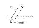
図5は、図2に示したスタイラスの具体的な構成例を示す模式的な部分断面図である。スタイラス2は、座標面の上を移動する輝点を検出して電気信号に変換した後この電気信号を処理して位置座標を算出する光デジタイザの入力に用いられ、描画操作に伴って座標面を移動する輝点を備えている。スタイラス2は描画操作を行うために操られる軸部21と輝点を形成する先端部22とを有する。先端部22はLEDなどからなる自発光体24とアクリル樹脂などからなる導光体23との結合である。導光体23は円錐または円柱の内部を底面から刳り貫いた形状を有し、その内面25または外面26の少なくとも一方が光拡散性を備えた透明部材からなり、且つ底面部に自発光体24が取り付けられている。本例では、内部を刳り貫いた導光体23の内面25および外面26の両者に凹凸が形成されている。この凹凸は透明で微細なプリズムからなる。このような凹凸は例えばシボ加工により得られる。係る構成によれば、スタイラスなどに組み込む発光体24として市販のLEDなどを使用することが可能になり、且つ発光体24から発する放射光を効率よく座標面に沿って放出することが可能である。
【0018】
図6は本発明に係る表示装置の第2実施形態を示す平面図である。この表示装置は座標面1上で間接的に放射光を発する指示体の位置座標を求めるため、光デジタイザを備えている。本実施形態では、指示体として指20が用いられている。光デジタイザは左右一対の光検出ユニット3L,3Rを備えており、座標面1の周辺に配されて指20から発した放射光を受光し電気信号に変換する。各検出ユニット3L,3Rには演算手段が内蔵されており、電気信号を処理して指20の位置座標を算出する。加えて、座標面1を照明する光源を内蔵した一対の照明ユニット30L,30Rが設けられている。左右の検出ユニット3L,3Rは照明を受けた指20の反射により間接的に発した放射光を受光する。左右一対の照明ユニット30L,30Rは内蔵された光源の点灯および消灯を繰り返して間欠的に座標面1をフラッシュ照明する。検出ユニット3L,3Rに備えられた演算手段はフラッシュ照明に同期して電気信号を処理する。
【0019】
図7は、図6に示した照明ユニット30Lの構成を示しており、(a)は平面図であり、(b)は側面図である。なお、他の照明ユニット30Rも同様な構成を有している。図示するように、照明ユニット30LはLEDなどの光源31を内蔵しており、その前方にはシリンドリカルレンズ32が取り付けられている。(a)に示すように、シリンドリカルレンズ32は座標面に対して水平な方向に関し光源光を拡散的に放射して座標面を広く照明するのに対し、(b)に示すように座標面と垂直な方向に関しては光源光をある程度集光して平行化している。
【0020】
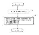
図8のフローチャートを参照して、図6に示した第2実施形態の動作を説明する。まず、ステップS1で左右の照明ユニット30L,30Rを点灯する。ステップS2で、左右の検出ユニット3L,3Rのイメージセンサから出力された電気信号を読み出し、バッファBUF1に格納する。ステップS3で左右の照明ユニット30L,30Rを消灯する。ステップS4で、再び左右の検出ユニット3L,3Rのイメージセンサから出力された電気信号を読み出し、別のバッファBUF2に格納する。最後にステップS5で、各検出ユニット3L,3Rの各画素毎にBUF1−BUF2の演算を行い、その後指20で示された位置座標を算出する。以上のように、本実施形態では左右一対の照明ユニット30L,30Rが点灯および消灯を繰り返して間欠的に座標面1をフラッシュ照明するとともに、演算手段はフラッシュ照明に同期して検出ユニット3L,3Rから出力される電気信号を処理している。係る構成により、ノイズの原因となる外乱光(バックグランド光)を除去した状態で、位置座標の演算が可能になる。本実施形態では照明を受けた指20の反射光を電気的な制御により外乱光と区別できるので、外乱光に強い光デジタイザを実現できる。また、PDPなどのディスプレイ6と組み合わせた時にその表示光の反射成分と照明光の反射成分を区別することが可能になる。なお図1に示した第1実施形態と同様に、本実施形態でも座標面1を囲む遮蔽枠4が設けられている。従って、上述した効果に加え、さらに周囲の外光が検出ユニットに入射することを防止できるので、さらに外乱光に強い光デジタイザを実現できる。
【0021】
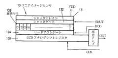
図9は、図6に示した検出ユニット3L,3Rのそれぞれに組み込まれるリニアイメージセンサ13の具体的な例を示す模式図である。本例では、リニアイメージセンサ13が、受光量に応じた電荷を蓄積して電気信号に変換する画素セル(電荷蓄積素子)133と電荷の蓄積を制御するシャッタゲート132とを備えている。このイメージセンサ13は前述したフラッシュ照明に同期してシャッタゲート132を開閉する。図示するように、リニアイメージセンサ13はシャッタドレイン131とシャッタゲート132と画素セル133とリードアウトゲート134とCCDアナログシフトレジスタ135と出力アンプ136とを備えている。シャッタドレイン131には電源電圧VDDが供給され、シャッタゲート132には制御信号SHUTが供給され、リードアウトゲートには制御信号ROGが供給され、CCDアナログシフトレジスタにはクロック信号CLKが供給される。出力アンプ136から電気信号OUTが得られる。
【0022】
図10のフローチャートを参照して、図9に示したシャッタ機能付きリニアイメージセンサ13の動作を説明する。まずステップS1で、制御信号SHUTを入力し、シャッタゲート132を開いて画素セル133に蓄積された電荷をシャッタドレイン131に逃がす。次にステップS2で、図6に示した左右の照明ユニット30L,30Rを点灯する。ステップS3で、一定時間経過後各照明ユニット30L,30Rを消灯する。この一定時間は例えば100μsecである。ステップS4で、制御信号ROGを入力しリードアウトゲート134を開いて電荷を画素セル133からCCDアナログシフトレジスタ135に移し、さらにCCDアナログシフトレジスタ135にクロック信号CLKを与えて画像データを読み出す。この画像データは出力アンプ136から電気信号OUTとして取り出される。最後にステップS5で、画像データに基づいて指20で指示された位置座標を演算する。本実施形態によれば、イメージセンサのシャッタ機能を使用することにより、照明をフラッシュ動作させて、フラッシュ期間のみに指やスタイラスなどの像を撮影できるので、外乱光が混入する期間を短縮化できる。これにより、表示光や外乱光の影響を少なくすることが可能である。
【0023】
図11は、本発明に係る光デジタイザの第3実施形態に用いる照明ユニットを示す模式的な平面図である。本実施形態では、照明ユニット30に内蔵された光源が赤色LED31r、緑色LED31gおよび青色LED31bの組からなる。また、これらのLEDの前方にはシリンドリカルレンズ32が配されている。照明ユニット30は各LED31r,31gおよび31bから発する複数の色光を切り替えて座標面をフラッシュ照明する。これに応じ、検出ユニットは特定の表面色を有する指示体の反射により生じた放射光をフラッシュ照明に同期して各色光別に受光する。検出ユニットに内蔵された演算手段はイメージセンサから出力される電気信号を処理して指示体の位置座標の算出に加えその表面色を識別する。
【0024】
図12は、図11に示した照明ユニット30を組み込んだ光デジタイザの動作を説明するためのフローチャートである。まずステップS1で、赤色LED31rのみを点灯してCCDイメージセンサから画像データを読み出す。この画像データは赤色照明下で得られたものであり、赤の色分解画像(赤画像)を示している。次にステップS2で緑色LED31gのみを点灯して、同じくCCDイメージセンサから画像データを読み出す。この画像データは緑色照明下で得られたものであり、緑の色分解画像(緑画像)を表わしている。最後にステップS3で青色LED31bのみを点灯して、CCDイメージセンサから画像データを読み出す。この画像データは青色照明下で得られたものであり、青の色分解画像(青画像)を示している。以上のように、本実施形態ではモノカラータイプのイメージセンサを使用しつつ、照明ユニットの色光を例えば赤、緑、青で切り替えることにより、各色に対応した色分解画像(赤画像、緑画像、青画像)を得るようにしている。
【0025】
図13は、上述した第3実施形態に用いるスタイラスの例を表わしている。図示するように、スタイラス2は軸部21と先端部22とを備えている。先端部22には緑の色光を強く反射する緑色部材27が取り付けられている。この他、赤色部材や青色部材を先端部22に取り付けたスタイラスも必要に応じ用いられる。
【0026】
図14は、上述した第3実施形態に係る光デジタイザの演算処理を示すフローチャートである。まず、ステップS1で赤画像、緑画像および青画像を読み込む。この後ステップS2で、緑画像:赤画像:青画像の比演算を各検出ユニットの各画素に対して行い、1:0:0に近い画素を抽出する。これにより、緑色部材27を先端部22に取り付けたスタイラス2を識別することができる。その後、抽出結果に基づいて座標演算を行う。以上のように、本実施形態では、照明ユニットは複数の色(波長)を持つ光源光を切り替えて座標面上に照射する。各々の波長を照射した時検出ユニットから出力される電気信号の変化からスタイラス2の色を識別する。これにより、座標情報に加え色情報を光デジタイザに入力することができる。即ち、モノカラータイプのイメージセンサを用いても、スタイラス2の色を識別することができるので、大変経済性に優れている。また、色識別を行うことにより外乱光の除去にも効果がある。
【0027】
図15は、本発明に係る光デジタイザの第4実施形態に用いるスタイラスを示す模式図である。前述した第3実施形態と同様に、本実施形態でも図11に示した色光切り替え型の照明ユニットを用いてスタイラスの色情報の検出を行っている。(a)に示すように、本スタイラス2は座標面の上を移動する輝点を検出して電気信号に変換した後この電気信号を処理して位置座標を出力する光デジタイザの入力に用いられ、描画操作に伴って座標面を移動する輝点を備えている。具体的には、スタイラス2は筆圧の変化を伴った描画操作を行うために操られる軸部21と外部の照明を反射して輝点を形成する反射体が装着された先端部22とを有する。この反射体は第一の色(例えば青色)を有し筆圧に応じて上下動するスライド部材28と、第二の色(例えば赤色)を有しスライド部材28を覆うカバー部材29とからなる。筆圧に応じて第一の色と第二の色の比率が変化することにより、描画操作に応じた位置座標の入力に加え筆圧の入力を可能にする。なお、スタイラス2の軸部21にスプリング28aが格納されており、これにより筆圧に応じたスライド部材28の上下動を実現している。
【0028】
(b)はスタイラス2に比較的強い筆圧が加わった状態を示し、(c)は比較的弱い筆圧が加わった状態を示している。スタイラス2を強くプッシュした時には検出ユニット3の視野11に赤色のカバー部材29が露出する。一方、強くプッシュしない場合には視野11に青色のスライド部材28が露出する。検出ユニット3は係るスタイラス2の先端部22の色変化を検出して、筆圧情報を得ることができる。この筆圧情報はスタイラスのペンダウン信号の入力に用いることができるとともに、マウスのクリック信号の入力に対応するものとして用いることができる。本実施形態では、照明ユニットは複数の色光を切り替えて座標面をフラッシュ照明し、スタイラス2は上下動動作に応じて表面色が変化し、検出ユニット3は表面色が変化するスタイラス2がフラッシュ照明を反射することで生じた放射光をフラッシュ照明に同期して各色光別に受光し、演算手段は検出ユニットから出力された電気信号を処理してスタイラス2の描画操作に応じた位置座標の算出に加え上下動操作に応じた表面色の変化を認識する。簡便な構造により、スタイラスが座標面に接触したことを示すペンダウン信号や筆圧信号を光デジタイザ本体に伝達できる。特に、スタイラス側では特別な回路部品や電池などを使用することなく、筆圧情報を光デジタイザの本体側に伝達できるので、経済性と耐久性に優れている。
【0029】
図16は本発明に係る表示装置および光デジタイザの第5実施形態を示す模式的な平面図である。基本的には、図1に示した第1実施形態と同様であり、座標面1の上にはスタイラス2と左右一対の検出ユニット3L,3Rが配置している。また、座標面1を囲むように遮蔽枠4が設けられているとともに、座標面1の下部にはPDPなどからなる大型のディスプレイ6が組み込まれている。
【0030】
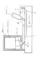
図17は図16に示した検出ユニット3の具体的な構成を示す模式的な断面図である。図示するように、本光デジタイザは、座標面1上で直接的または間接的に放射光を発するスタイラス2の位置座標を求めるため、座標面1の周辺に配され放射光を受光して電気信号に変換する検出ユニット3と、これに内蔵され電気信号を処理して位置座標を算出する演算手段と、検出ユニット3の視野11を座標面1から所定の高さ以下に制限して受光可能な放射光の範囲を座標面1に対して平行化するレンズ9とを備えている。本実施形態では、検出ユニット3はカラーTVカメラ12を利用している。このカラーTVカメラ12はカラーイメージセンサを内蔵している。また、上述したレンズ9はカラーTVカメラ12に取り付けられた撮像レンズである。レンズ9は座標面1に垂直な光軸を有する。ミラー16が座標面1の上に配されており、座標面1に平行な放射光の成分を直角に反射してレンズ9に導く。係る構成により、スタイラス2の先端部22から発した放射光のうち実質上座標面1と平行な成分のみをカラーイメージセンサの受光面に集光して、受光可能な放射光の範囲を座標面1に対して平行化している。即ち、検出ユニット3はスタイラス2の像をイメージセンサに結像させるレンズ9を備えており、このレンズ9の視野直前に光路を直角に折り曲げる反射手段としミラー16を配している。係る構成により、レンズ9として市販のTVカメラ用レンズを使用する際、カメラユニットの取り付けと位置合わせの調整が容易になる。さらに、座標面1の周囲に遮蔽枠4を設けることで、ディスプレイ6の画面15から放射される表示光を含む外乱光に対して強い光デジタイザを実現できる。なお、本実施形態では検出ユニット3はカラーイメージセンサを用いており、スタイラス2に割り当てられた色に応じた放射光を受光して対応する電気信号を出力し、演算手段はこの電気信号を処理してスタイラス2の位置座標の算出に加えその色を識別することができる。このように、スタイラスの色を識別して消しゴムなどの特定の機能をスタイラスに割り当てることができる。また、先端部22の色が異なる複数のスタイラス2の同時使用を可能にする。さらに、色を識別することにより外乱光の排除が可能である。
【0031】
図18は、図16および図17に示した第5実施形態に用いるスタイラスの具体的な例を示す模式的な断面図である。この光スタイラスは、基本的には図5に示した光スタイラスと類似の構造を有している。図示するように、スタイラス2は軸部21と先端部22とに分かれている。軸部21にはプリント基板21pが格納されており、その上にスイッチ21s、サイドノブ21n、回路部品21cなどが搭載されている。また、プリント基板21pには筆圧検出器21dも取り付けられている。一方、先端部22は発光体と導光体23とからなる。発光体は赤LED24r、緑LED24gおよび青LED24bの組からなり、レンズ24aで被覆されている。これらのLEDチップはプリント基板21pに搭載された回路部品21cにより点灯動作を制御される。導光体23は内部を刳り貫いた円柱形状の透明アクリル樹脂などからなり、その内面25および外面26には凹凸が形成されており、所望の光散乱性を備えている。
【0032】
図19は、図18に示した光スタイラスの回路構成を示すブロック図である。筆圧検出器21dには反転アンプ21iおよびLED駆動アンプ21aを介して赤LED24rが接続されている。また、LED駆動アンプ21aを介して青LED24bも接続されている。一方、スイッチ21sにはLED駆動アンプ21aを介して緑LED24gが接続されている。
【0033】
図20のフローチャートを参照して、上述した第5実施形態に係る光デジタイザの動作を説明する。まずステップS1で、カラーTVカメラ12から出力された撮像信号を読み込み、バッファBUF(赤)、BUF(緑)、BUF(青)に格納する。次にステップS2で、(BUF(赤)+BUF(緑)+BUF(青))の値を演算し、これに基づいてスタイラス2の位置座標を算出する。次にステップS3で、(BUF(赤)+BUF(緑)+BUF(青))のピーク値を取る画素の値をレジスタPEAK(赤)、PEAK(緑)、PEAK(青)に格納する。ステップS4で各レジスタPEAK(赤)、PEAK(緑)、PEAK(青)の値に基づき、筆圧情報やスイッチのオン/オフ情報を算出する。図19から明らかなように、筆圧検出器21dで検出される筆圧が強い程、青LED24bの発光量が大きくなる。逆に、筆圧検出器21dが検出する筆圧が弱い程、赤LED24rの発光量が強くなる。このような発光量の変化を検出してステップS4で筆圧を求めている。また、図19から明らかなように、サイドノブ21nの操作に応じたスイッチ21sのON/OFFに応じて緑LED24gが点灯/消灯する。この変化をステップS4で検出し、スイッチのON/OFF情報を得ている。
【0034】
以上説明したように、本実施形態では、座標面1上で直接的または間接的に放射光を発しながら描画操作およびそれに付随する付帯操作を行うスタイラス2と、座標面1の周辺に配され放射光を受光して電気信号に変換する検出ユニット3と、この電気信号を処理してスタイラス2の位置座標を算出する演算手段とを備えた光デジタイザにおいて、スタイラス2は付帯操作に応じて放射光に含まれる色成分を変化させる変調手段を備えており、検出ユニット3は放射光に含まれる色成分に応じた電気信号を処理し、演算手段は検出ユニット3から出力された電気信号を処理してスタイラス2の描画操作に応じた位置座標の算出に加え付帯操作に応じた付随情報を取得している。スタイラス2は座標面1の上を移動する輝点を検出して電気信号に変換した後この電気信号を処理して位置座標を算出する光デジタイザの入力に用いられ、描画操作に伴って座標面1を移動する輝点を備えている。スタイラス2は描画操作およびそれに付随する付帯操作を行うために操られる軸部21と輝点を形成する自発光体(赤LED24r、緑LED24g、青LED24b)が装着された先端部22とを有する。軸部21は付帯操作に応じて自発光体を制御して輝点の色調を変化させる変調手段(筆圧検出器21dやスイッチ21sなど)を備えており、描画操作に応じた位置座標の入力に加え付帯操作に応じた付随情報の入力を可能にしている。即ち、スタイラス2は複数の波長の光を切り替えて、又はある比率で同時に発する3色のLED24r,24g,24bを備え、これらの自発光体の波長の制御を筆圧やスイッチの状態(即ち、スタイラスの付帯情報)に応じて成すようにしている。検出ユニット側は係るスタイラス2の色変化を検出する手段を備えており、スタイラスの色を識別することにより付帯情報をデジタイザ本体側に伝達できる。本実施形態によれば、特別な赤外線リンクや無線リンクを使うことなく、スタイラスから入力された付帯情報を光デジタイザ側に伝達できる。
【0035】
図21は、本発明に係る表示装置および光デジタイザの第6実施形態を示す模式的な平面図である。本実施形態では、異なる色が割り当てられた複数のスタイラスの同時使用を可能にしている。ディスプレイ6の上に規定された座標面1には例えば赤色LED24rを備えた赤スタイラス2rと青色LED24bを備えた青スタイラス2bが配されている。座標面1の周辺には左右一対の検出ユニット3L,3Rが配置されている。一対の検出ユニット3L,3Rには座標演算部19r,19bが接続されている。一方の座標演算部19rは左右の検出ユニット3L,3Rから出力された赤画像信号を処理して、赤スタイラス2rの位置座標を出力する。他方の座標演算部19bは左右一対の検出ユニット3L,3Rから出力された青画像信号を処理して、青スタイラス2bの位置座標を出力する。このように、個々のスタイラスに割り当てられた色に対応した色分解画像を出力する検出ユニット3L,3Rは先の実施形態のものを用いることができる。
【0036】
図22は、本発明に係る光デジタイザの第7実施形態を示す模式的な部分断面図である。基本的には、図17に示した第5実施形態と類似しており、対応する部分には対応する参照番号を付して理解を容易にしている。本実施形態では、第5実施形態で用いたミラーに代えて、ハーフミラー16hを用いている。このハーフミラー16hの後方にはシリンドリカルレンズ32を介して光源31が配されている。光源31はハーフミラー16hを介して再帰反射部材22tを有するスタイラス2を照明する。検出ユニット3に内蔵したTVカメラ12は照明を受けたスタイラス2から再帰反射した放射光をハーフミラー16hを介して受光する。再帰反射部材22tとしては例えば多数の小さなコーナーキューブプリズムを用いることができる。これは極めて効率のよい再帰反射部材であり、光源31の発光強度は比較的小さくて済む。係る構成により、照明効率を高めることができ且つ外乱光によるスタイラスからの不要反射の入光を防ぐことができる。
【0037】
図23は、本発明に係る表示装置および光デジタイザの第8実施形態を示す平面図である。基本的には、本実施形態は図6に示した第2実施形態と類似している。ディスプレイ6の上に規定された座標面1上で放射光を発するスタイラス2の位置座標を求めるため、左右一対の検出ユニット3L,3Rが座標面の周辺に配されており、放射光を受光して電気信号に変換する。さらに、この電気信号を処理して位置座標を算出する。また、座標面1を照明する光源として、蛍光ランプ31eが配されている。蛍光ランプ31eはある波長の光源光を用いて座標面1を照明し、左右の検出ユニット3L,3Rは蛍光体22eを有するスタイラス2による光源光の反射により生じた別の波長の放射光を選択的に受光する光学フィルター39L,39Rをそれぞれ備えている。蛍光ランプ31eは紫外波長の光源光を用いて座標面1を照明し、左右の検出ユニット3L,3Rは蛍光体22eを備えたスタイラス2による光源光の反射で生じた可視波長の放射光を選択的に受光する光学フィルター39L,39Rを備えている。係る構成によれば、スタイラス2以外からの反射光を区別し排除できるので、大変強力な外乱光対策になる。また、フィルターを用いることにより、表示光や外乱光が検出ユニットに入るのを防ぐことができる。さらに、光源としては広く普及しているブラックライトブルー蛍光ランプ31e等を用いることができ、さらにスタイラス2の先端に設ける蛍光体22eは入手容易な蛍光物質を利用することができるので、経済性に優れている。また、照明が操作者の目に入って表示を妨害するのを防ぐことができる。
【0038】
【発明の効果】
以上説明したように、本発明によれば、表示光を含む外乱光に対して強い光デジタイザを実現することができた。また、検出ユニットの取り付けの制約を減らし、コンパクトな実装が可能な光デジタイザが得られた。さらに、スタイラスの色を検出することが可能になり、複数の異なるスタイラスなどを識別したり、複数のスタイラスによる同時入力を実現できた。さらに、筆圧などスタイラスの操作に付随する情報を光デジタイザの本体側に経済的に伝達することができた。以上の効果は光デジタイザのみではなく、これと大型のディスプレイとを組み合わせた表示装置に応用した場合、特に顕著な効果が得られる。
【図面の簡単な説明】
【図1】本発明に係る光デジタイザの第1実施形態を示す平面図である。
【図2】本発明に係る光デジタイザの第1実施形態を示す断面図である。
【図3】第1実施形態に組み込まれるレンズを示す平面図である。
【図4】第1実施形態の変形例を示す模式図である。。
【図5】第1実施形態に用いられるスタイラスの一例を示す模式図である。
【図6】本発明に係る光デジタイザの第2実施形態を示す平面図である。
【図7】第2実施形態に組み込まれる照明ユニットを示す模式図である。
【図8】第2実施形態の動作説明に供するフローチャートである。
【図9】第2実施形態に用いるリニアイメージセンサの一例を示す模式図である。
【図10】図9に示したリニアイメージセンサの動作説明に供するフローチャートである。
【図11】第3実施形態に用いられる照明ユニットを示す模式図である。
【図12】図11に示した照明ユニットの動作説明に供するフローチャートである。
【図13】第3実施形態に用いるスタイラスを示す模式図である。
【図14】第3実施形態の動作説明に供するフローチャートである。
【図15】第4実施形態に用いるスタイラスを示す模式図である。
【図16】第5実施形態を示す平面図である。
【図17】第5実施形態に組み込まれる検出ユニットを示す断面図である。
【図18】第5実施形態に用いるスタイラスを示す断面図である。
【図19】図18に示したスタイラスの回路構成を示すブロック図である。
【図20】第5実施形態の動作説明に供するフローチャートである。
【図21】第6実施形態を示す平面図である。
【図22】第7実施形態を示す断面図である。
【図23】第8実施形態を示す平面図である。
【図24】従来の光デジタイザを示す模式図である。
【図25】従来の光デジタイザを示す側面図である。
【図26】リニアイメージセンサの動作説明に供する模式図である。
【符号の説明】
1・・・座標面、2・・・スタイラス、3L・・・左検出ユニット、3R・・・右検出ユニット、4・・・遮蔽枠、5・・・パーソナルコンピュータ、6・・・ディスプレイ、9・・・レンズ、11・・・視野、13・・・リニアイメージセンサ、15・・・画面[0001]
BACKGROUND OF THE INVENTION
The present invention optically detects the position indicated by a finger, a stylus, or a pointing stick (hereinafter collectively referred to as a pointer) on the coordinate plane, and the position of the pointer from the side of the coordinate plane by an image sensor. This relates to optical digitizers that are input to computers. In particular, the present invention relates to an optical digitizer suitable for constructing a pen computer system in which a screen is matched with a coordinate plane of an optical digitizer in combination with a large plasma display or liquid crystal display. The present invention also relates to a display device provided with such an optical digitizer. Furthermore, the present invention relates to an optical stylus that is preferable as an indicator used in such an optical digitizer.
[0002]
[Prior art]
Recently, a large-sized plasma display (PDP) having a diagonal size of 40 inches or more has been developed to a practical stage. A liquid crystal display (LCD) has also been prototyped on a 40-inch class large screen using a technique for connecting a plurality of panels. Such a large display device is convenient for displaying a monitor screen of a personal computer in a conference room, for example, and giving a presentation. If you can do the pointing operation of the personal computer or the marking operation to mark the explanation part using the mouse, you can touch the screen directly with your finger or touch the screen with the stylus, the receiving side will Since the person who is explaining and the screen displaying the explanation contents can be observed at the same time, it is possible to obtain the same feeling as when using the blackboard, and the effect of the presentation is further enhanced. For this reason, conventionally, a display device has been developed in which a display, a digitizer, and a touch panel are combined to match an output screen and an input coordinate plane.
[0003]
Conventionally, as a digitizer considered to be relatively easy to combine with a large display, a so-called stereo method is known, in which a luminescent point of a stylus is imaged by two TV cameras and the position thereof is obtained. As shown in FIG. 24, in this stereo method, a
[0004]
FIG. 25 shows a side shape of the conventional display device shown in FIG. The screen of the
[0005]
[Problems to be solved by the invention]
However, a conventional optical digitizer using a TV camera is vulnerable to disturbance light such as indoor illumination light or sunlight entering from a window, and has a problem of causing malfunction. In addition, when combined with a display, the optical digitizer detects light emitted from the screen, causing a malfunction. The PDP is a self-luminous display and emits a considerable amount of light from the screen. Further, when the LCD is a transmissive type using a backlight, a large amount of light from the back surface is emitted from the screen. In particular, the indicator is not a structure having a light emitter and directly forming a bright spot, but in the case of an indicator that reflects external light and indirectly forms a bright spot, such as a finger, since the light amount of the bright spot is small, It is strongly affected by ambient light and malfunctions become prominent. Also, in order to capture bright points on the coordinate plane from the side, it is necessary to attach a TV camera to the periphery of the display, but due to the field of view of the TV camera and its shape, there are many restrictions on the installation surface and compact mounting. It was an obstacle to realize. In addition, the alignment operation of the TV camera with respect to the coordinate plane is complicated and difficult.
[0006]
In view of the above, an object of the present invention is to provide an optical digitizer that can operate stably without being affected by disturbance light including light emitted from a display. It is another object of the present invention to provide an optical digitizer that can be mounted in a compact manner, excluding restrictions on the mounting of a detection unit used to detect a bright spot of an indicator. It is another object of the present invention to provide an optical digitizer that detects the color of an indicator such as a finger or a stylus and identifies a plurality of different indicators or enables simultaneous input by a plurality of indicators. It is another object of the present invention to provide an optical digitizer that can efficiently input incidental information such as writing pressure in addition to position information. It is another object of the present invention to provide a display device suitable for a conference system combining an optical digitizer and a large display. In addition, an object is to provide an optical stylus optimal for an optical digitizer.
[0007]
[Means for solving the problems]
In order to achieve the object of the present invention described above, the following measures were taken. That is, the optical digitizer according to the present invention has, as a basic configuration, in order to obtain the position coordinates of the indicator that emits radiated light directly or indirectly on the coordinate plane. Detection means for receiving light and converting it into an electrical signal, and arithmetic means for processing the electrical signal and calculating position coordinates are provided. The field of the detection means is limited to a predetermined height or less from the coordinate plane, and the range of radiated light that can be received is parallel to the coordinate plane.Limited to light And optical means for shielding, and shielding means for removing unnecessary light other than radiated light from the visual field, which is arranged so as to surround the periphery of the coordinate plane.More A light source for illuminating the coordinate plane is provided, and the detecting means receives radiated light indirectly emitted by reflection of the illuminated indicator. The light source is repeatedly turned on and off to intermittently flash the coordinate plane, and the arithmetic means processes an electrical signal output from the detection means in synchronization with the flash illumination. The light source switches a plurality of color lights to illuminate a coordinate plane, and the detection means receives radiated light generated by reflection of an indicator having a specific surface color for each color light in synchronization with the flash illumination, and performs the calculation. The means processes the electrical signal output from the detection means to identify the surface color in addition to calculating the position coordinates of the indicator.Somehow The light source illuminates the coordinate surface using light source light of a certain wavelength, and the detecting means is an optical device that selectively receives emitted light of another wavelength caused by reflection of the light source light by an indicator having a fluorescent screen. Has a filter. Preferably, the light source illuminates a coordinate plane using light source light having an ultraviolet wavelength, and the detecting means selectively receives visible light radiation generated by reflection of the light source light by the fluorescent surface of the indicator. It has. In some cases, the detection means comprises a color image sensor, receives the radiated light corresponding to the color assigned to the indicator and outputs a corresponding electrical signal, and the computing means processes the electrical signal and outputs the corresponding electrical signal. In addition to calculating the position coordinates of the indicator, the color of the indicator is identified.
[0008]
The optical stylus according to the present invention is used for input of an optical digitizer that detects a bright spot moving on a coordinate plane and converts it to an electrical signal and then processes the electrical signal to calculate a position coordinate. Along with this, there is a bright spot that moves on the coordinate plane. As a feature, the present optical stylus has a shaft portion that is manipulated to perform a drawing operation and a tip portion that forms a bright spot, and the tip portion is composed of a combination of a self-luminous body and a light guide, and The light body has a shape that penetrates the inside of the cone or cylinder from the bottom surface, at least one of the inner surface or the outer surface is made of a transparent member having light diffusibility, and the self-luminous body is attached to the bottom surface portion. . Preferably, the present optical stylus has a shaft portion that is operated to perform a drawing operation and an incidental operation associated therewith, and a tip portion to which a self-luminous body that forms a bright spot is attached, and the shaft portion is used for the incidental operation. Correspondingly, a modulation means for controlling the self-luminous body to change the color tone of the bright spot is provided, and in addition to the input of the position coordinates according to the drawing operation, the incidental information according to the incidental operation can be input. In some cases, the present optical stylus has a shaft portion that is manipulated to perform a drawing operation with a change in writing pressure, and a tip portion that is equipped with a reflector that reflects external illumination to form a bright spot. The reflector includes a slide member that has a first color and moves up and down in response to writing pressure, and a cover member that has a second color and covers the slide member. By changing the ratio between the color and the second color, it is possible to input the pen pressure in addition to the input of the position coordinates according to the drawing operation.
[0009]
The display device according to the present invention, as a basic configuration, receives the radiated light arranged around the coordinate plane in order to obtain the position coordinates of the indicator that emits radiated light directly or indirectly on the coordinate plane. Detecting means for converting to an electric signal, and calculating means for processing the electric signal to calculate position coordinates, and further, a display constituting a screen overlapping the coordinate plane, and displaying the obtained position coordinates on the screen Output means. As a feature, the display device limits the field of view of the detection means to a predetermined width in the vertical direction from the coordinate plane, and optical means for collimating the range of light that can be received with respect to the coordinate plane; Shielding means having a vertical width sufficient to remove unnecessary light other than radiated light from the visual field.
[0010]
According to the present invention, the optical digitizer has a structure that is not easily affected by disturbance light including display light emitted from the display. In addition, the mounting of the detection means on the coordinate plane is reduced, and a compact mounting is possible. Furthermore, by detecting the color of a pointer such as a finger or a stylus, a plurality of different pointers can be identified and simultaneous input by a plurality of pointers is possible. In addition, stylus incidental information such as writing pressure in addition to position coordinates can be efficiently transmitted to the optical digitizer body.
[0011]
DETAILED DESCRIPTION OF THE INVENTION
Hereinafter, embodiments of the present invention will be described in detail with reference to the drawings. FIG. 1 is a schematic plan view showing a first embodiment of a display device according to the present invention. This display device has a structure in which an optical digitizer and a
[0012]
Next, the operation of the first embodiment shown in FIG. 1 will be described. In the present display device, an
[0013]
FIG. 2 schematically shows a cross-sectional structure of the display device shown in FIG. In the figure, only the left detection unit 3L is shown, but the right detection unit 3R has the same configuration. Each of the left detection unit 3L and the right detection unit 3R includes a
[0014]
FIG. 26 is a schematic diagram for explaining the function of the
[0015]
FIG. 3 is a schematic plan view showing the shape of the lens group 9 shown in FIG. As shown in the figure, the lens group 9 is processed into a flat shape by cutting the top and bottom of the spherical surface, and can be arranged in parallel on the coordinate plane. The lens group 9 having such a flat shape is obtained as a plastic molded lens, for example.
[0016]
FIG. 4 shows a modification of the structure shown in FIG. In this modified example, a prism 17 constituting a refracting means is used instead of the mirror 16 constituting the reflecting means. The prism 17 refracts the radiated light collected by the lens group 9 and guides it to the light receiving surface of the
[0017]
FIG. 5 is a schematic partial cross-sectional view showing a specific configuration example of the stylus shown in FIG. The
[0018]
FIG. 6 is a plan view showing a second embodiment of the display device according to the present invention. This display device is provided with an optical digitizer in order to obtain the position coordinates of an indicator that emits radiation light indirectly on the coordinate
[0019]
7 shows the configuration of the
[0020]
The operation of the second embodiment shown in FIG. 6 will be described with reference to the flowchart of FIG. First, the left and
[0021]
FIG. 9 is a schematic diagram showing a specific example of the
[0022]
The operation of the
[0023]
FIG. 11 is a schematic plan view showing an illumination unit used in the third embodiment of the optical digitizer according to the present invention. In the present embodiment, the light source built in the
[0024]
FIG. 12 is a flowchart for explaining the operation of the optical digitizer incorporating the
[0025]
FIG. 13 shows an example of a stylus used in the third embodiment described above. As shown in the drawing, the
[0026]
FIG. 14 is a flowchart showing the arithmetic processing of the optical digitizer according to the third embodiment described above. First, in step S1, a red image, a green image, and a blue image are read. Thereafter, in step S2, a green image: red image: blue image ratio calculation is performed on each pixel of each detection unit, and pixels close to 1: 0: 0 are extracted. Thereby, the
[0027]
FIG. 15 is a schematic diagram showing a stylus used in the fourth embodiment of the optical digitizer according to the present invention. Similar to the third embodiment described above, the present embodiment also detects stylus color information using the color light switching type illumination unit shown in FIG. As shown in (a), the
[0028]
(B) shows a state in which a relatively strong writing pressure is applied to the
[0029]
FIG. 16 is a schematic plan view showing a display device and an optical digitizer according to a fifth embodiment of the present invention. Basically, it is the same as that of the first embodiment shown in FIG. 1, and a
[0030]
FIG. 17 is a schematic cross-sectional view showing a specific configuration of the
[0031]
FIG. 18 is a schematic cross-sectional view showing a specific example of a stylus used in the fifth embodiment shown in FIGS. 16 and 17. This optical stylus basically has a structure similar to that of the optical stylus shown in FIG. As shown, the
[0032]
FIG. 19 is a block diagram showing a circuit configuration of the optical stylus shown in FIG. A
[0033]
The operation of the optical digitizer according to the fifth embodiment will be described with reference to the flowchart of FIG. First, in step S1, an imaging signal output from the
[0034]
As described above, in the present embodiment, the
[0035]
FIG. 21 is a schematic plan view showing a sixth embodiment of the display device and the optical digitizer according to the present invention. In this embodiment, a plurality of styluses assigned different colors can be used simultaneously. On the coordinate
[0036]
FIG. 22 is a schematic partial sectional view showing a seventh embodiment of the optical digitizer according to the present invention. Basically, it is similar to the fifth embodiment shown in FIG. 17, and corresponding portions are denoted by corresponding reference numerals for easy understanding. In the present embodiment, a half mirror 16h is used instead of the mirror used in the fifth embodiment. A
[0037]
FIG. 23 is a plan view showing an eighth embodiment of a display device and an optical digitizer according to the present invention. Basically, this embodiment is similar to the second embodiment shown in FIG. In order to obtain the position coordinates of the
[0038]
【The invention's effect】
As described above, according to the present invention, an optical digitizer that is strong against disturbance light including display light can be realized. In addition, an optical digitizer that can be mounted in a compact manner with reduced detection unit mounting restrictions was obtained. Furthermore, it became possible to detect the color of the stylus, and to identify a plurality of different styluses and to realize simultaneous input with a plurality of styluses. Furthermore, information accompanying the stylus operation such as writing pressure could be transmitted economically to the optical digitizer body. The effects described above are not only optical digitizers, but are particularly remarkable when applied to a display device that combines this with a large display.
[Brief description of the drawings]
FIG. 1 is a plan view showing a first embodiment of an optical digitizer according to the present invention.
FIG. 2 is a cross-sectional view showing a first embodiment of an optical digitizer according to the present invention.
FIG. 3 is a plan view showing a lens incorporated in the first embodiment.
FIG. 4 is a schematic diagram showing a modification of the first embodiment. .
FIG. 5 is a schematic diagram showing an example of a stylus used in the first embodiment.
FIG. 6 is a plan view showing a second embodiment of the optical digitizer according to the present invention.
FIG. 7 is a schematic diagram showing an illumination unit incorporated in the second embodiment.
FIG. 8 is a flowchart for explaining the operation of the second embodiment.
FIG. 9 is a schematic diagram showing an example of a linear image sensor used in the second embodiment.
10 is a flowchart for explaining the operation of the linear image sensor shown in FIG. 9;
FIG. 11 is a schematic diagram showing an illumination unit used in the third embodiment.
12 is a flowchart for explaining the operation of the illumination unit shown in FIG.
FIG. 13 is a schematic diagram showing a stylus used in the third embodiment.
FIG. 14 is a flowchart for explaining the operation of the third embodiment;
FIG. 15 is a schematic diagram showing a stylus used in the fourth embodiment.
FIG. 16 is a plan view showing a fifth embodiment.
FIG. 17 is a cross-sectional view showing a detection unit incorporated in the fifth embodiment.
FIG. 18 is a cross-sectional view showing a stylus used in the fifth embodiment.
19 is a block diagram showing a circuit configuration of the stylus shown in FIG.
FIG. 20 is a flowchart for explaining the operation of the fifth embodiment;
FIG. 21 is a plan view showing a sixth embodiment.
FIG. 22 is a cross-sectional view showing a seventh embodiment.
FIG. 23 is a plan view showing an eighth embodiment.
FIG. 24 is a schematic view showing a conventional optical digitizer.
FIG. 25 is a side view showing a conventional optical digitizer.
FIG. 26 is a schematic diagram for explaining the operation of the linear image sensor.
[Explanation of symbols]
DESCRIPTION OF
Claims (15)
Translated fromJapanese該検出手段の視野を該座標面から所定の高さ以下に制限して受光可能な放射光の範囲を該座標面に対して平行な光に限定する光学手段と、
該座標面の周囲を囲むように配され該視野から放射光以外の不要光を除去する遮蔽手段とを有し、
座標面を照明する光源を備えているとともに、前記検出手段は照明を受けた指示体の反射により間接的に発した放射光を受光し、
前記光源は複数の色光を切り替えながら点灯および消灯を繰り返して間欠的に座標面をフラッシュ照明し、
前記検出手段は特定の表面色を有する指示体の反射により生じた放射光をフラッシュ照明に同期して各色光別に受光し、
前記演算手段はフラッシュ照明に同期して該検出手段から出力される電気信号を処理して指示体の位置座標の算出に加え、表面色を識別することを特徴とする光デジタイザ。In order to obtain the position coordinates of the indicator that emits radiation directly or indirectly on the coordinate plane, detection means arranged around the coordinate plane to receive the radiation and convert it into an electrical signal, and the electrical signal In an optical digitizer provided with an arithmetic means for calculating the position coordinates by processing
Optical meansfor limiting the field of the detection means to a predetermined height or less from the coordinate plane and limiting the range of radiated light that can be received to lightparallel to the coordinate plane;
Possess a shielding means for removing unnecessary light except the emitted light from the visual field is disposed to surround the periphery of the coordinateplane,
A light source for illuminating the coordinate plane is provided, and the detection means receives radiation emitted indirectly by reflection of the illuminated indicator,
The light source intermittently flashes the coordinate surface by repeatedly turning on and off while switching a plurality of color lights,
The detecting means receives the emitted light generated by the reflection of the indicator having a specific surface color for each color light in synchronization with the flash illumination,
An optical digitizer characterizedin that thearithmetic means processes an electrical signal output from the detection means in synchronization with flash illumination to identify the surface color in addition to calculating the position coordinates of the indicator .
該検出手段の視野を該座標面から所定の高さ以下に制限して受光可能な放射光の範囲を該座標面に対して平行な光に限定する光学手段と、
該座標面の周囲を囲むように配され該視野から放射光以外の不要光を除去する遮蔽手段とを有し、
座標面を照明する光源を備えているとともに、前記検出手段は照明を受けた指示体の反射により間接的に発した放射光を受光し、
前記光源はある波長の光源光を用いて座標面を照明し、前記検出手段は蛍光面を有する指示体による光源光の反射により生じた別の波長の放射光を選択的に受光する光学フィルターを備えていることを特徴とする光デジタイザ。In order to obtain the position coordinates of the indicator that emits radiation directly or indirectly on the coordinate plane, detection means arranged around the coordinate plane to receive the radiation and convert it into an electrical signal, and the electrical signal In an optical digitizer provided with an arithmetic means for calculating the position coordinates by processing
Optical means for limiting the field of the detection means to a predetermined height or less from the coordinate plane and limiting the range of radiated light that can be received to light parallel to the coordinate plane;
Shielding means for removing unnecessary light other than radiated light from the visual field, which is arranged so as to surround the periphery of the coordinate plane,
A light source for illuminating the coordinate plane is provided, and the detection means receives radiation emitted indirectly by reflection of the illuminated indicator,
The light source illuminates a coordinate plane using light source light of a certain wavelength, and the detection means includes an optical filter that selectively receives emitted light of another wavelength caused by reflection of the light source light by an indicator having a fluorescent screen.light digitizer characterized in that it comprises.
該検出手段の視野を該座標面から所定の高さ以下に制限して受光可能な放射光の範囲を該座標面に対して平行な光に限定する光学手段と、
該座標面の周囲を囲むように配され該視野から放射光以外の不要光を除去する遮蔽手段とを有し、
前記検出手段はカラーイメージセンサからなり、指示体に割り当てられた色に応じた放射光を受光して対応する電気信号を出力し、前記演算手段は該電気信号を処理して該指示体の位置座標の算出に加え指示体の色を識別することを特徴とする光デジタイザ。In order to obtain the position coordinates of the indicator that emits radiation directly or indirectly on the coordinate plane, detection means arranged around the coordinate plane to receive the radiation and convert it into an electrical signal, and the electrical signal In an optical digitizer provided with an arithmetic means for calculating the position coordinates by processing
Optical means for limiting the field of the detection means to a predetermined height or less from the coordinate plane and limiting the range of radiated light that can be received to light parallel to the coordinate plane;
Shielding means for removing unnecessary light other than radiated light from the visual field, which is arranged so as to surround the periphery of the coordinate plane,
The detection means comprises a color image sensor, receives radiated light corresponding to the color assigned to the indicator and outputs a corresponding electrical signal, and the arithmetic means processes the electrical signal to process the position of the indicator.light digitizer characterized by identifying the color of the indicator in addition to the calculation of the coordinates.
前記光源は複数の色光を切り替えながら点灯および消灯を繰り返して間欠的に座標面をフラッシュ照明し、
前記検出手段はフラッシュ照明を受けた指示体の反射により間接的に発した放射光を受光し、その際特定の表面色を有する指示体の反射により生じた放射光をフラッシュ照明に同期して各色光別に受光し、
前記演算手段はフラッシュ照明に同期して該検出手段から出力される電気信号を処理して指示体の位置座標の算出に加え、表面色を識別することを特徴とする光デジタイザ。In order to obtain the position coordinates of the indicator that emits radiated light indirectly on the coordinate plane, detection means disposed around the coordinate plane for receiving the radiated light and converting it into an electric signal, and processing the electric signal An optical digitizer comprising a computing means for calculating position coordinates and a light source for illuminating the coordinate plane,
The light source intermittentlyflashes thecoordinate surface by repeatedly turning on and off while switching a plurality of color lights,
The detecting means receives radiated light indirectly emitted by reflection of the indicator that has received flash illumination, and at that time, radiated light generated by reflection of the indicator having a specific surface color is synchronized with the flash illumination for each color. Receive light separately,
An optical digitizer characterizedin that thearithmetic means processes an electrical signal output from the detection means in synchronization with flash illumination to identify the surface color in addition to calculating the position coordinates of the indicator .
前記光源はある波長の光源光を用いて座標面を照明し、前記検出手段は蛍光面を有する指示体による光源光の反射により生じた別の波長の放射光を選択的に受光する光学フィルターを備えていることを特徴とする光デジタイザ。In order to obtain the position coordinates of the indicator that emits radiated light on the coordinate plane, detection means arranged around the coordinate plane for receiving the radiated light and converting it into an electric signal, and processing the electric signal to position coordinates An optical digitizer comprising a computing means for calculating the light source and a light source for illuminating the coordinate plane,
The light source illuminates a coordinate plane using light source light of a certain wavelength, and the detection means includes an optical filter that selectively receives emitted light of another wavelength caused by reflection of the light source light by an indicator having a fluorescent screen. An optical digitizer characterized by comprising.
前記指示体は付帯操作に応じて放射光に含まれる色成分を変化させる変調手段を備え、前記検出手段は放射光に含まれる色成分に応じた電気信号を出力し、前記演算手段は該検出手段から出力された電気信号を処理して指示体の描画操作に応じた位置座標の算出に加え付帯操作に応じた付随情報を取得することを特徴とする光デジタイザ。An indicator that performs a drawing operation and an incidental operation accompanying it while emitting radiation light directly or indirectly on the coordinate plane, and detection for receiving the radiation light and converting it into an electrical signal around the coordinate plane In an optical digitizer comprising: means; and calculating means for processing the electrical signal to calculate the position coordinates of the indicator,
The indicator includes a modulation unit that changes a color component included in the emitted light according to an incidental operation, the detection unit outputs an electric signal corresponding to the color component included in the emitted light, and the calculation unit detects the detection An optical digitizer characterized in that the electrical signal output from the means is processed to acquire accompanying information in accordance with an incidental operation in addition to calculation of position coordinates in accordance with a drawing operation of an indicator.
前記光源は複数の色光を切り替えて座標面をフラッシュ照明し、前記指示体は上下動操作に応じて表面色が変化し、前記検出手段は表面色が変化する指示体がフラッシュ照明を反射することで生じた放射光を該フラッシュ照明に同期して各色光別に受光し、前記演算手段は該検出手段から出力される電気信号を処理して指示体の描画操作に応じた位置座標の算出に加え上下動操作に応じた表面色の変化を認識することを特徴とする光デジタイザ。An indicator for performing a drawing operation and an accompanying vertical movement operation while emitting radiation light indirectly on the coordinate plane; and a detecting means arranged around the coordinate plane to receive the radiation light and convert it into an electrical signal; , An optical digitizer comprising an arithmetic means for processing the electrical signal to calculate the position coordinates of the indicator, and a light source for illuminating the coordinate plane.
The light source switches a plurality of color lights and flashes the coordinate plane, the indicator changes its surface color in response to a vertical movement operation, and the detection means reflects the flash illumination when the indicator whose surface color changes The calculation means receives the radiated light generated in step S3 in synchronization with the flash illumination, and the calculation means processes the electrical signal output from the detection means to calculate the position coordinates according to the drawing operation of the indicator. An optical digitizer characterized by recognizing a change in surface color in response to a vertical movement operation.
描画操作を行うために操られる軸部と輝点を形成する先端部とを有し、前記先端部は自発光体と導光体との結合からなり、前記導光体は円錐または円柱の内部を底面から刳り貫いた形状を有し、その内面または外面の少なくとも一方が光拡散性を備えた透明部材からなり、且つ底面部に自発光体が取り付けられていることを特徴とする光スタイラス。A bright spot that moves on the coordinate plane in accordance with the drawing operation is used to input a light digitizer that detects the bright spot moving on the coordinate plane and converts it to an electrical signal and then processes the electrical signal to calculate the position coordinates. A light stylus with dots,
A shaft portion that is manipulated to perform a drawing operation and a tip portion that forms a bright spot, the tip portion comprising a combination of a self-luminous body and a light guide body, and the light guide body is inside a cone or cylinder An optical stylus comprising a transparent member having a light diffusibility at least one of its inner surface and outer surface, and a self-luminous body attached to the bottom surface portion.
描画操作およびそれに付随する付帯操作を行うために操られる軸部と輝点を形成する自発光体が装着された先端部とを有し、前記軸部は付帯操作に応じて自発光体を制御して輝点の色調を変化させる変調手段を備えており、描画操作に応じた位置座標の入力に加え付帯操作に応じた付随情報の入力を可能にすることを特徴とする光スタイラス。A bright spot that moves on the coordinate plane in accordance with the drawing operation is used to input a light digitizer that detects the bright spot moving on the coordinate plane and converts it to an electrical signal and then processes the electrical signal to calculate the position coordinates. A light stylus with dots,
It has a shaft portion that is operated to perform a drawing operation and an incidental operation accompanying it, and a tip portion that is equipped with a self-luminous body that forms a bright spot, and the shaft portion controls the self-luminous body according to the incidental operation. An optical stylus comprising a modulation means for changing the color tone of the bright spot, and enabling the input of incidental information in accordance with an incidental operation in addition to the input of position coordinates in accordance with a drawing operation.
筆圧の変化を伴なった描画操作を行うために操られる軸部と外部の照明を反射して輝点を形成する反射体が装着された先端部とを有し、前記反射体は第一の色を有し筆圧に応じて上下動するスライド部材と、第二の色を有し該スライド部材を覆うカバー部材とからなり、筆圧に応じて第一の色と第二の色の比率が変化することにより、描画操作に応じた位置座標の入力に加え筆圧の入力を可能にすることを特徴とする光スタイラス。A bright spot that moves on the coordinate plane in accordance with the drawing operation is used to input a light digitizer that detects the bright spot moving on the coordinate plane and converts it to an electrical signal and then processes the electrical signal to calculate the position coordinates. A light stylus with dots,
A shaft portion that is manipulated to perform a drawing operation with a change in writing pressure, and a tip portion that is mounted with a reflector that reflects external illumination to form a bright spot, the reflector being a first A slide member that moves up and down according to the writing pressure and a cover member that has the second color and covers the sliding member, and the first color and the second color according to the writing pressure. An optical stylus capable of inputting writing pressure in addition to inputting position coordinates in accordance with a drawing operation by changing the ratio.
前記光源はある波長の光源光を用いて座標面を照明し、前記検出手段は蛍光面を有する指示体による光源光の反射により生じた別の波長の放射光を選択的に受光する光学フィルターを備えていることを特徴とする表示装置。In order to obtain the position coordinates of the indicator that emits radiated light on the coordinate plane, detection means arranged around the coordinate plane for receiving the radiated light and converting it into an electric signal, and processing the electric signal to position coordinates A display device comprising: a calculation means for calculating a light source; a light source that illuminates the coordinate plane; a display that forms a screen overlapping the coordinate plane; and an output means that displays the obtained position coordinates on the screen. ,
The light source illuminates a coordinate plane using light source light of a certain wavelength, and the detection means includes an optical filter that selectively receives emitted light of another wavelength caused by reflection of the light source light by an indicator having a fluorescent screen. A display device comprising the display device.
前記指示体は付帯操作に応じて放射光に含まれる色成分を変化させる変調手段を備え、前記検出手段は放射光に含まれる色成分に応じた電気信号を出力し、前記該演算手段は該検出手段から出力された電気信号を処理して指示体の描画操作に応じた位置座標の算出に加え付帯操作に応じた付随情報を取得することを特徴とする表示装置。An indicator that performs a drawing operation and an incidental operation accompanying it while emitting radiation light directly or indirectly on the coordinate plane, and detection for receiving the radiation light and converting it into an electrical signal around the coordinate plane Means and processing means for processing the electrical signal to calculate the position coordinates of the indicator, and further comprising: a display constituting a screen overlapping the coordinate plane; and an output means for displaying the obtained position coordinates on the screen. In the provided display device,
The indicator includes a modulation unit that changes a color component included in the emitted light according to an incidental operation, the detection unit outputs an electrical signal corresponding to the color component included in the emitted light, and the calculation unit A display device that processes an electrical signal output from a detection means to acquire accompanying information according to an incidental operation in addition to calculating a position coordinate according to a drawing operation of an indicator.
前記光源は複数の色光を切り替えて座標面をフラッシュ照明し、前記指示体は上下動操作に応じて表面色が変化し、前記検出手段は表面色が変化する指示体がフラッシュ照明を反射することで生じた放射光を該フラッシュ照明に同期して各色光別に受光し、前記演算手段は該検出手段から出力される電気信号を処理して指示体の描画操作に応じた位置座標の算出に加え上下動操作に応じた表面色の変化を認識することを特徴とする表示装置。An indicator for performing a drawing operation and an accompanying vertical movement operation while emitting radiation light indirectly on the coordinate plane; and a detecting means arranged around the coordinate plane to receive the radiation light and convert it into an electrical signal; A calculation means for processing the electrical signal to calculate the position coordinates of the indicator, a light source for illuminating the coordinate plane, a display constituting a screen overlapping the coordinate plane, and the obtained position coordinates for the screen In a display device comprising output means for projecting to
The light source switches a plurality of color lights and flashes the coordinate plane, the indicator changes its surface color in response to a vertical movement operation, and the detection means reflects the flash illumination when the indicator whose surface color changes The calculation means receives the radiated light generated in step S3 in synchronization with the flash illumination, and the calculation means processes the electrical signal output from the detection means to calculate the position coordinates according to the drawing operation of the indicator. A display device characterized by recognizing a change in surface color in response to a vertical movement operation.
Priority Applications (4)
| Application Number | Priority Date | Filing Date | Title |
|---|---|---|---|
| JP17280297AJP3876942B2 (en) | 1997-06-13 | 1997-06-13 | Optical digitizer |
| US09/024,001US6100538A (en) | 1997-06-13 | 1998-02-13 | Optical digitizer and display means for providing display of indicated position |
| DE19810452ADE19810452B4 (en) | 1997-06-13 | 1998-03-11 | Optical digitizer |
| US09/428,902US6441362B1 (en) | 1997-06-13 | 1999-10-28 | Stylus for optical digitizer |
Applications Claiming Priority (1)
| Application Number | Priority Date | Filing Date | Title |
|---|---|---|---|
| JP17280297AJP3876942B2 (en) | 1997-06-13 | 1997-06-13 | Optical digitizer |
Publications (2)
| Publication Number | Publication Date |
|---|---|
| JPH113170A JPH113170A (en) | 1999-01-06 |
| JP3876942B2true JP3876942B2 (en) | 2007-02-07 |
Family
ID=15948650
Family Applications (1)
| Application Number | Title | Priority Date | Filing Date |
|---|---|---|---|
| JP17280297AExpired - Fee RelatedJP3876942B2 (en) | 1997-06-13 | 1997-06-13 | Optical digitizer |
Country Status (3)
| Country | Link |
|---|---|
| US (2) | US6100538A (en) |
| JP (1) | JP3876942B2 (en) |
| DE (1) | DE19810452B4 (en) |
Families Citing this family (238)
| Publication number | Priority date | Publication date | Assignee | Title |
|---|---|---|---|---|
| JP2000105671A (en)* | 1998-05-11 | 2000-04-11 | Ricoh Co Ltd | Coordinate input / detection device and electronic blackboard system |
| JP4033582B2 (en)* | 1998-06-09 | 2008-01-16 | 株式会社リコー | Coordinate input / detection device and electronic blackboard system |
| US20100008551A9 (en)* | 1998-08-18 | 2010-01-14 | Ilya Schiller | Using handwritten information |
| US7268774B2 (en)* | 1998-08-18 | 2007-09-11 | Candledragon, Inc. | Tracking motion of a writing instrument |
| US6664954B1 (en)* | 1998-11-05 | 2003-12-16 | Canon Kabushiki Kaisha | Coordinate input indicator |
| US6335724B1 (en)* | 1999-01-29 | 2002-01-01 | Ricoh Company, Ltd. | Method and device for inputting coordinate-position and a display board system |
| JP4093665B2 (en)* | 1999-02-04 | 2008-06-04 | リコーエレメックス株式会社 | Coordinate detection device |
| JP2000284895A (en)* | 1999-03-31 | 2000-10-13 | Hitachi Software Eng Co Ltd | Coordinate input pen, electronic board using it, coordinate input system and electronic board system |
| JP3830121B2 (en)* | 1999-06-10 | 2006-10-04 | 株式会社 ニューコム | Optical unit for object detection and position coordinate input device using the same |
| JP3670896B2 (en)* | 1999-08-06 | 2005-07-13 | 日立ソフトウエアエンジニアリング株式会社 | Electronic board system |
| US6727885B1 (en) | 1999-09-07 | 2004-04-27 | Nikon Corporation | Graphical user interface and position or attitude detector |
| US20010010514A1 (en)* | 1999-09-07 | 2001-08-02 | Yukinobu Ishino | Position detector and attitude detector |
| JP3898392B2 (en)* | 1999-09-10 | 2007-03-28 | 株式会社リコー | Coordinate input device |
| JP4052498B2 (en)* | 1999-10-29 | 2008-02-27 | 株式会社リコー | Coordinate input apparatus and method |
| JP3819654B2 (en)* | 1999-11-11 | 2006-09-13 | 株式会社シロク | Optical digitizer with indicator identification function |
| US6457792B1 (en)* | 1999-11-29 | 2002-10-01 | Xerox Corporation | Method for effecting actions over vertical surfaces |
| US6368002B1 (en)* | 1999-11-29 | 2002-04-09 | Xerox Corporation | Parking mechanism for storing and exchanging end effectors used in a system for performing actions over vertical surfaces |
| JP2001159955A (en)* | 1999-12-02 | 2001-06-12 | Ricoh Co Ltd | Coordinate input / detection / display device |
| JP2001184161A (en) | 1999-12-27 | 2001-07-06 | Ricoh Co Ltd | Information input method, information input device, writing input device, writing data management method, display control method, portable electronic writing device, and recording medium |
| JP3881148B2 (en)* | 2000-02-18 | 2007-02-14 | 株式会社リコー | Photodetection device for coordinate detection, coordinate input / detection device, electronic blackboard, mounting position detection method, and storage medium |
| US6924791B1 (en)* | 2000-03-09 | 2005-08-02 | Palmone, Inc. | Method and apparatus for automatic power-up and power-down of a computer system based on the positions of an associated stylus and/or hinge |
| JP2001265516A (en)* | 2000-03-16 | 2001-09-28 | Ricoh Co Ltd | Coordinate input device |
| KR20020092393A (en)* | 2000-03-21 | 2002-12-11 | 레오나드 레이필 | Multi user retro reflector data input |
| JP2001282445A (en)* | 2000-03-31 | 2001-10-12 | Ricoh Co Ltd | Coordinate input / detection device and information display input device |
| WO2001078052A1 (en)* | 2000-04-05 | 2001-10-18 | Dimensional Media Associates, Inc. | Methods and apparatus for virtual touchscreen computer interface controller |
| JP4393030B2 (en)* | 2000-04-14 | 2010-01-06 | 富士通株式会社 | Optical position detection device and recording medium |
| KR100865598B1 (en)* | 2000-05-29 | 2008-10-27 | 브이케이비 인코포레이티드 | Virtual data input device and method for inputting alphanumeric characters and other data |
| JP2001344060A (en)* | 2000-05-31 | 2001-12-14 | Matsushita Electric Ind Co Ltd | Pen for interactive board |
| US7692625B2 (en) | 2000-07-05 | 2010-04-06 | Smart Technologies Ulc | Camera-based touch system |
| US6803906B1 (en) | 2000-07-05 | 2004-10-12 | Smart Technologies, Inc. | Passive touch system and method of detecting user input |
| JP3851763B2 (en) | 2000-08-04 | 2006-11-29 | 株式会社シロク | Position detection device, position indicator, position detection method, and pen-down detection method |
| JP2002062979A (en)* | 2000-08-23 | 2002-02-28 | Newcom:Kk | Position detecting device and position detecting method |
| NO311740B1 (en)* | 2000-09-11 | 2002-01-14 | Tormod Njoelstad | Drawing, writing and pointing tools for computer-based presentations and office work |
| US7058204B2 (en)* | 2000-10-03 | 2006-06-06 | Gesturetek, Inc. | Multiple camera control system |
| JP2002118738A (en)* | 2000-10-10 | 2002-04-19 | Canon Inc | Image display device and method, information processing unit using the image display device, and storage medium |
| KR20020087938A (en)* | 2000-12-27 | 2002-11-23 | 엔티티 도꼬모 인코퍼레이티드 | Handwriting data input device and method, and authenticating device and method |
| US6717073B2 (en) | 2000-12-29 | 2004-04-06 | Intel Corporation | Wireless display systems, styli, and associated methods |
| JP2002229728A (en)* | 2001-02-02 | 2002-08-16 | Newcom:Kk | Position detector with cmos linear image sensor |
| DE10110260A1 (en)* | 2001-03-02 | 2002-09-05 | Weis Steffen | Cursor representation on a monitor or screen in which position on the screen of the signal generator and the indicator coincide using a beam, wave or particle, as a signaler |
| US20020021291A1 (en)* | 2001-03-26 | 2002-02-21 | Cook Brandt A. | Stylus with light emitting diode |
| US7279646B2 (en)* | 2001-05-25 | 2007-10-09 | Intel Corporation | Digital signature collection and authentication |
| US6919880B2 (en) | 2001-06-01 | 2005-07-19 | Smart Technologies Inc. | Calibrating camera offsets to facilitate object position determination using triangulation |
| JP4250884B2 (en)* | 2001-09-05 | 2009-04-08 | パナソニック株式会社 | Electronic blackboard system |
| US20030085883A1 (en)* | 2001-11-07 | 2003-05-08 | Mao-Sung Wu | Selector pen for touch screen |
| US7257255B2 (en)* | 2001-11-21 | 2007-08-14 | Candledragon, Inc. | Capturing hand motion |
| US7426804B2 (en)* | 2002-02-06 | 2008-09-23 | Andersen Corporation | Specialty display window |
| US7053967B2 (en) | 2002-05-23 | 2006-05-30 | Planar Systems, Inc. | Light sensitive display |
| US7009663B2 (en)* | 2003-12-17 | 2006-03-07 | Planar Systems, Inc. | Integrated optical light sensitive active matrix liquid crystal display |
| AU2002336341A1 (en)* | 2002-02-20 | 2003-09-09 | Planar Systems, Inc. | Light sensitive display |
| EP1488639A1 (en)* | 2002-03-22 | 2004-12-22 | British Telecommunications Public Limited Company | Interactive video system |
| JP3975892B2 (en)* | 2002-05-02 | 2007-09-12 | 富士ゼロックス株式会社 | Position measurement system |
| US7427983B1 (en)* | 2002-06-02 | 2008-09-23 | Steelcase Development Corporation | Visual communication system |
| US20030234346A1 (en)* | 2002-06-21 | 2003-12-25 | Chi-Lei Kao | Touch panel apparatus with optical detection for location |
| US20040001144A1 (en)* | 2002-06-27 | 2004-01-01 | Mccharles Randy | Synchronization of camera images in camera-based touch system to enhance position determination of fast moving objects |
| US7623115B2 (en)* | 2002-07-27 | 2009-11-24 | Sony Computer Entertainment Inc. | Method and apparatus for light input device |
| TW200428097A (en)* | 2002-10-01 | 2004-12-16 | Koninkl Philips Electronics Nv | Multi-layered collimator |
| US20050212780A1 (en)* | 2002-10-22 | 2005-09-29 | Timo Tokkonen | Method and arrangement for input mode selection |
| US7133031B2 (en)* | 2002-10-31 | 2006-11-07 | Microsoft Corporation | Optical system design for a universal computing device |
| US6954197B2 (en)* | 2002-11-15 | 2005-10-11 | Smart Technologies Inc. | Size/scale and orientation determination of a pointer in a camera-based touch system |
| US6972401B2 (en)* | 2003-01-30 | 2005-12-06 | Smart Technologies Inc. | Illuminated bezel and touch system incorporating the same |
| US8508508B2 (en) | 2003-02-14 | 2013-08-13 | Next Holdings Limited | Touch screen signal processing with single-point calibration |
| US8456447B2 (en) | 2003-02-14 | 2013-06-04 | Next Holdings Limited | Touch screen signal processing |
| US7280348B2 (en)* | 2003-02-14 | 2007-10-09 | Intel Corporation | Positioning mechanism for a pen-based computing system |
| US7629967B2 (en) | 2003-02-14 | 2009-12-08 | Next Holdings Limited | Touch screen signal processing |
| US20080084374A1 (en) | 2003-02-20 | 2008-04-10 | Planar Systems, Inc. | Light sensitive display |
| US6947032B2 (en)* | 2003-03-11 | 2005-09-20 | Smart Technologies Inc. | Touch system and method for determining pointer contacts on a touch surface |
| US7532206B2 (en) | 2003-03-11 | 2009-05-12 | Smart Technologies Ulc | System and method for differentiating between pointers used to contact touch surface |
| FR2853423B1 (en)* | 2003-03-20 | 2005-07-15 | Simag Dev | INPUT DEVICE COMPRISING AN OPTICAL SENSOR FOLLOWED BY A FILTERING MEANS |
| US7256772B2 (en)* | 2003-04-08 | 2007-08-14 | Smart Technologies, Inc. | Auto-aligning touch system and method |
| EP1628196A4 (en)* | 2003-05-19 | 2008-10-29 | Eit Co Ltd | Position sensor using area image sensor |
| JP4185825B2 (en)* | 2003-07-01 | 2008-11-26 | キヤノン株式会社 | Coordinate input device, control method therefor, information processing device, and program |
| US7411575B2 (en)* | 2003-09-16 | 2008-08-12 | Smart Technologies Ulc | Gesture recognition method and touch system incorporating the same |
| JP2007506180A (en)* | 2003-09-22 | 2007-03-15 | コニンクリユケ フィリップス エレクトロニクス エヌ.ブイ. | Coordinate detection system for display monitor |
| US7274356B2 (en)* | 2003-10-09 | 2007-09-25 | Smart Technologies Inc. | Apparatus for determining the location of a pointer within a region of interest |
| US20050110777A1 (en)* | 2003-11-25 | 2005-05-26 | Geaghan Bernard O. | Light-emitting stylus and user input device using same |
| US20050134749A1 (en)* | 2003-12-19 | 2005-06-23 | Adiel Abileah | Reflection resistant display |
| US7355593B2 (en) | 2004-01-02 | 2008-04-08 | Smart Technologies, Inc. | Pointer tracking across multiple overlapping coordinate input sub-regions defining a generally contiguous input region |
| US20050156901A1 (en)* | 2004-01-20 | 2005-07-21 | Guolin Ma | Touch screen display system |
| US7232986B2 (en)* | 2004-02-17 | 2007-06-19 | Smart Technologies Inc. | Apparatus for detecting a pointer within a region of interest |
| US7385594B2 (en)* | 2004-02-19 | 2008-06-10 | Au Optronics Corporation | Position encoded sensing device and a method thereof |
| US7249431B1 (en) | 2004-02-19 | 2007-07-31 | William Rose | Light-activated illuminating device |
| US20050195591A1 (en)* | 2004-03-04 | 2005-09-08 | Garcia Raymond J. | LED writing instrument and glow-in-the-dark phosphorous writing surface |
| US7379563B2 (en)* | 2004-04-15 | 2008-05-27 | Gesturetek, Inc. | Tracking bimanual movements |
| US7773139B2 (en) | 2004-04-16 | 2010-08-10 | Apple Inc. | Image sensor with photosensitive thin film transistors |
| JP4266878B2 (en)* | 2004-04-22 | 2009-05-20 | Necディスプレイソリューションズ株式会社 | Video display device |
| US7460110B2 (en) | 2004-04-29 | 2008-12-02 | Smart Technologies Ulc | Dual mode touch system |
| US7492357B2 (en) | 2004-05-05 | 2009-02-17 | Smart Technologies Ulc | Apparatus and method for detecting a pointer relative to a touch surface |
| US7538759B2 (en) | 2004-05-07 | 2009-05-26 | Next Holdings Limited | Touch panel display system with illumination and detection provided from a single edge |
| US8120596B2 (en) | 2004-05-21 | 2012-02-21 | Smart Technologies Ulc | Tiled touch system |
| US20060028457A1 (en)* | 2004-08-08 | 2006-02-09 | Burns David W | Stylus-Based Computer Input System |
| WO2006027423A1 (en)* | 2004-08-09 | 2006-03-16 | Simag Developpement | Input device comprising an optical sensor and a filter means |
| US20060045240A1 (en)* | 2004-08-31 | 2006-03-02 | Buchner Gregory C | Method and apparatus for delayed answering of telecommunications request |
| US20060139338A1 (en)* | 2004-12-16 | 2006-06-29 | Robrecht Michael J | Transparent optical digitizer |
| WO2006074289A2 (en)* | 2005-01-07 | 2006-07-13 | Gesturetek, Inc. | Detecting and tracking objects in images |
| ATE551675T1 (en) | 2005-01-21 | 2012-04-15 | Qualcomm Inc | MOTION BASED TRACKING |
| WO2006090386A2 (en)* | 2005-02-24 | 2006-08-31 | Vkb Inc. | A virtual keyboard device |
| US7646377B2 (en)* | 2005-05-06 | 2010-01-12 | 3M Innovative Properties Company | Position digitizing using an optical stylus to image a display |
| US7719519B2 (en)* | 2005-06-24 | 2010-05-18 | Hewlett-Packard Development Company, L.P. | Input device which emits and/or reflects optical electromagnetic radiation for use on a display screen |
| CN1888977B (en)* | 2005-06-29 | 2010-09-08 | Ge医疗系统环球技术有限公司 | X-ray photographic system |
| US7782296B2 (en)* | 2005-11-08 | 2010-08-24 | Microsoft Corporation | Optical tracker for tracking surface-independent movements |
| US7534988B2 (en)* | 2005-11-08 | 2009-05-19 | Microsoft Corporation | Method and system for optical tracking of a pointing object |
| US20070109271A1 (en)* | 2005-11-14 | 2007-05-17 | Phison Electronics Corp. | [a portable storage device with handwritten input device] |
| JP4341661B2 (en)* | 2005-11-22 | 2009-10-07 | ソニー株式会社 | Input device, input method, and input device manufacturing method |
| US20070165007A1 (en)* | 2006-01-13 | 2007-07-19 | Gerald Morrison | Interactive input system |
| CN100543578C (en)* | 2006-01-17 | 2009-09-23 | 联想(北京)有限公司 | A projector and method for obtaining coordinates of bright spots |
| EP1821184A3 (en)* | 2006-02-08 | 2007-11-14 | Almeva AG | System and method for interacting with a display through a shop window |
| US7755026B2 (en)* | 2006-05-04 | 2010-07-13 | CandleDragon Inc. | Generating signals representative of sensed light that is associated with writing being done by a user |
| US8656282B2 (en)* | 2007-01-31 | 2014-02-18 | Fall Front Wireless Ny, Llc | Authoring tool for providing tags associated with items in a video playback |
| US20080029316A1 (en)* | 2006-08-07 | 2008-02-07 | Denny Jaeger | Method for detecting position of input devices on a screen using infrared light emission |
| JP4757144B2 (en)* | 2006-08-22 | 2011-08-24 | キヤノン株式会社 | Coordinate input device, control method therefor, and program |
| US7948189B2 (en)* | 2006-09-26 | 2011-05-24 | Siemens Industry, Inc. | Application of microsystems for lighting control |
| US8022941B2 (en)* | 2006-10-12 | 2011-09-20 | Disney Enterprises, Inc. | Multi-user touch screen |
| KR20080044017A (en)* | 2006-11-15 | 2008-05-20 | 삼성전자주식회사 | touch screen |
| US9442607B2 (en) | 2006-12-04 | 2016-09-13 | Smart Technologies Inc. | Interactive input system and method |
| WO2008073289A2 (en)* | 2006-12-08 | 2008-06-19 | Johnson Controls Technology Company | Display and user interface |
| DE102007021537B4 (en)* | 2006-12-13 | 2020-01-02 | Lg Display Co., Ltd. | Display unit with multi-touch detection function |
| WO2008083205A2 (en)* | 2006-12-29 | 2008-07-10 | Gesturetek, Inc. | Manipulation of virtual objects using enhanced interactive system |
| TWI336854B (en) | 2006-12-29 | 2011-02-01 | Ibm | Video-based biometric signature data collecting method and apparatus |
| US20080169132A1 (en)* | 2007-01-03 | 2008-07-17 | Yao Ding | Multiple styli annotation system |
| US20080166175A1 (en)* | 2007-01-05 | 2008-07-10 | Candledragon, Inc. | Holding and Using an Electronic Pen and Paper |
| US8115753B2 (en) | 2007-04-11 | 2012-02-14 | Next Holdings Limited | Touch screen system with hover and click input methods |
| EP2017697B1 (en)* | 2007-07-20 | 2014-05-14 | Brainlab AG | Input pen for a touch sensitive medical monitor |
| US8094137B2 (en) | 2007-07-23 | 2012-01-10 | Smart Technologies Ulc | System and method of detecting contact on a display |
| US8384693B2 (en) | 2007-08-30 | 2013-02-26 | Next Holdings Limited | Low profile touch panel systems |
| WO2009029767A1 (en) | 2007-08-30 | 2009-03-05 | Next Holdings, Inc. | Optical touchscreen with improved illumination |
| TWI396119B (en)* | 2007-10-28 | 2013-05-11 | Univ Lunghwa Sci & Technology | Touch screen |
| US8405636B2 (en) | 2008-01-07 | 2013-03-26 | Next Holdings Limited | Optical position sensing system and optical position sensor assembly |
| US20090213093A1 (en)* | 2008-01-07 | 2009-08-27 | Next Holdings Limited | Optical position sensor using retroreflection |
| JP2009250772A (en)* | 2008-04-04 | 2009-10-29 | Sony Corp | Position detection system, position detection method, program, object determination system and object determination method |
| JP5025552B2 (en)* | 2008-04-16 | 2012-09-12 | キヤノン株式会社 | Touch panel |
| JP2008217819A (en)* | 2008-04-24 | 2008-09-18 | Ricoh Co Ltd | Information input device, information input method, information input program, and storage medium |
| US8902193B2 (en) | 2008-05-09 | 2014-12-02 | Smart Technologies Ulc | Interactive input system and bezel therefor |
| JP2010019822A (en)* | 2008-07-10 | 2010-01-28 | Pixart Imaging Inc | Sensing system |
| TW201007254A (en)* | 2008-08-04 | 2010-02-16 | Pixart Imaging Inc | Image-sensing module and image-sensing system |
| KR20100030022A (en)* | 2008-09-09 | 2010-03-18 | 삼성전기주식회사 | Opto-touch screen |
| US8446389B2 (en)* | 2008-10-15 | 2013-05-21 | Lenovo (Singapore) Pte. Ltd | Techniques for creating a virtual touchscreen |
| US8525776B2 (en)* | 2008-10-27 | 2013-09-03 | Lenovo (Singapore) Pte. Ltd | Techniques for controlling operation of a device with a virtual touchscreen |
| US8339378B2 (en) | 2008-11-05 | 2012-12-25 | Smart Technologies Ulc | Interactive input system with multi-angle reflector |
| WO2010055737A1 (en) | 2008-11-14 | 2010-05-20 | 株式会社ソニー・コンピュータエンタテインメント | Operating device |
| TWI510966B (en)* | 2009-01-19 | 2015-12-01 | Wistron Corp | Input system and related method for an electronic device |
| US20100207912A1 (en)* | 2009-02-13 | 2010-08-19 | Arima Lasers Corp. | Detection module and an optical detection system comprising the same |
| US20100207909A1 (en)* | 2009-02-13 | 2010-08-19 | Ming-Cho Wu | Detection module and an optical detection device comprising the same |
| TW201030578A (en)* | 2009-02-13 | 2010-08-16 | Arima Lasers Corp | A detection module and an optical detection system comprising the same |
| WO2010110681A2 (en)* | 2009-03-25 | 2010-09-30 | Next Holdings Ltd | Frames for optical touch detection systems |
| CN101872269B (en)* | 2009-04-21 | 2013-08-28 | 鸿富锦精密工业(深圳)有限公司 | Touch control system |
| JP2010257089A (en)* | 2009-04-22 | 2010-11-11 | Xiroku:Kk | Optical position detector |
| CN102597796B (en)* | 2009-06-16 | 2015-02-04 | 百安托国际有限公司 | Two-dimensional position sensing system and its sensor |
| JP2011014107A (en)* | 2009-07-06 | 2011-01-20 | Hitachi Solutions Ltd | Coordinate detection device |
| US8692768B2 (en) | 2009-07-10 | 2014-04-08 | Smart Technologies Ulc | Interactive input system |
| CN101957665B (en)* | 2009-07-15 | 2014-02-19 | 鸿富锦精密工业(深圳)有限公司 | A drawing board system |
| JP5374266B2 (en)* | 2009-07-22 | 2013-12-25 | 株式会社シロク | Optical position detector |
| US8519984B2 (en)* | 2009-08-20 | 2013-08-27 | Acer Incorporated | Input device and display system having the same |
| US20120169674A1 (en)* | 2009-09-15 | 2012-07-05 | Nec Corporation | Input device and input system |
| CN102053777A (en)* | 2009-11-04 | 2011-05-11 | 鸿富锦精密工业(深圳)有限公司 | Handwriting input device |
| KR100974894B1 (en)* | 2009-12-22 | 2010-08-11 | 전자부품연구원 | 3d space touch apparatus using multi-infrared camera |
| CN102109929A (en)* | 2009-12-28 | 2011-06-29 | 鸿富锦精密工业(深圳)有限公司 | Electronic whiteboard system |
| US8842096B2 (en)* | 2010-01-08 | 2014-09-23 | Crayola Llc | Interactive projection system |
| EP2343629A3 (en) | 2010-01-08 | 2015-01-21 | Integrated Digital Technologies, Inc. | Stylus and touch input system |
| KR101070865B1 (en)* | 2010-01-08 | 2011-10-10 | 김성한 | camera module for optical touch screen |
| TW201126397A (en)* | 2010-01-18 | 2011-08-01 | Acer Inc | Optical touch control display and method thereof |
| US9189086B2 (en)* | 2010-04-01 | 2015-11-17 | Smart Technologies Ulc | Interactive input system and information input method therefor |
| US20110241987A1 (en)* | 2010-04-01 | 2011-10-06 | Smart Technologies Ulc | Interactive input system and information input method therefor |
| TWI400641B (en)* | 2010-04-23 | 2013-07-01 | Waltop Int Corp | Optical touch apparatus |
| WO2011134118A1 (en)* | 2010-04-30 | 2011-11-03 | Nokia Corporation | Method and apparatus for providing user input |
| US8593402B2 (en)* | 2010-04-30 | 2013-11-26 | Verizon Patent And Licensing Inc. | Spatial-input-based cursor projection systems and methods |
| TW201209671A (en)* | 2010-08-17 | 2012-03-01 | Waltop Int Corp | Optical touch locating system and method thereof |
| TWI414980B (en)* | 2010-09-10 | 2013-11-11 | Chip Goal Electronics Corp | Virtual touch control apparatus and method thereof |
| US20120075196A1 (en)* | 2010-09-23 | 2012-03-29 | Nokia Corporation | Apparatus and method for user input |
| JP5598232B2 (en)* | 2010-10-04 | 2014-10-01 | ソニー株式会社 | Information processing apparatus, information processing system, and information processing method |
| US9104306B2 (en) | 2010-10-29 | 2015-08-11 | Avago Technologies General Ip (Singapore) Pte. Ltd. | Translation of directional input to gesture |
| US20120105373A1 (en)* | 2010-10-31 | 2012-05-03 | Chih-Min Liu | Method for detecting touch status of surface of input device and input device thereof |
| JP2012103938A (en)* | 2010-11-11 | 2012-05-31 | Seiko Epson Corp | Optical detection system and program |
| GB2487043B (en)* | 2010-12-14 | 2013-08-14 | Epson Norway Res And Dev As | Camera-based multi-touch interaction and illumination system and method |
| US9310923B2 (en) | 2010-12-03 | 2016-04-12 | Apple Inc. | Input device for touch sensitive devices |
| KR20120066814A (en)* | 2010-12-15 | 2012-06-25 | 주식회사 동해과학기술연구원 | Optical touch pannel |
| SG184582A1 (en)* | 2011-03-07 | 2012-10-30 | Creative Tech Ltd | A method, system and electronic device for association based identification |
| US20120262366A1 (en)* | 2011-04-15 | 2012-10-18 | Ingeonix Corporation | Electronic systems with touch free input devices and associated methods |
| US8638320B2 (en) | 2011-06-22 | 2014-01-28 | Apple Inc. | Stylus orientation detection |
| US8928635B2 (en) | 2011-06-22 | 2015-01-06 | Apple Inc. | Active stylus |
| US9329703B2 (en) | 2011-06-22 | 2016-05-03 | Apple Inc. | Intelligent stylus |
| US9292131B2 (en)* | 2011-07-14 | 2016-03-22 | 3M Innovative Properties Company | Light guide for backlight |
| US9035911B2 (en)* | 2011-07-14 | 2015-05-19 | 3M Innovative Properties Company | Digitizer using position-unique optical signals |
| US9035912B2 (en)* | 2011-07-14 | 2015-05-19 | 3M Innovative Properties Company | Digitizer for multi-display system |
| TWI479390B (en)* | 2011-08-19 | 2015-04-01 | Tpk Touch Solutions Inc | An optical touch system and a positioning method thereof |
| CN103019458B (en)* | 2011-09-20 | 2016-05-18 | 原相科技股份有限公司 | Optical touch control system and localization method thereof |
| TW201317839A (en)* | 2011-10-25 | 2013-05-01 | Au Optronics Corp | Stylus, touch sensitive display system and touch sensitive display method |
| US9323348B2 (en)* | 2011-11-09 | 2016-04-26 | Crayola Llc | Stylus having sensing and transmitting capabilities |
| TWI451312B (en)* | 2011-12-19 | 2014-09-01 | Pixart Imaging Inc | Optical touch device and light source assembly |
| WO2013104062A1 (en) | 2012-01-11 | 2013-07-18 | Smart Technologies Ulc | Interactive input system and method |
| US9354748B2 (en)* | 2012-02-13 | 2016-05-31 | Microsoft Technology Licensing, Llc | Optical stylus interaction |
| US9075566B2 (en) | 2012-03-02 | 2015-07-07 | Microsoft Technoogy Licensing, LLC | Flexible hinge spine |
| US9460029B2 (en) | 2012-03-02 | 2016-10-04 | Microsoft Technology Licensing, Llc | Pressure sensitive keys |
| TWI457794B (en)* | 2012-03-28 | 2014-10-21 | Wistron Corp | Stylus and optomechanical system capable of detecting stroke pressure |
| JP6217058B2 (en)* | 2012-05-09 | 2017-10-25 | セイコーエプソン株式会社 | Image display system |
| US20130300590A1 (en) | 2012-05-14 | 2013-11-14 | Paul Henry Dietz | Audio Feedback |
| US9176604B2 (en) | 2012-07-27 | 2015-11-03 | Apple Inc. | Stylus device |
| US9652090B2 (en) | 2012-07-27 | 2017-05-16 | Apple Inc. | Device for digital communication through capacitive coupling |
| US9557845B2 (en) | 2012-07-27 | 2017-01-31 | Apple Inc. | Input device for and method of communication with capacitive devices through frequency variation |
| US8964379B2 (en) | 2012-08-20 | 2015-02-24 | Microsoft Corporation | Switchable magnetic lock |
| KR101238025B1 (en)* | 2012-08-24 | 2013-03-04 | 김성한 | Camera module for optical touch screen |
| US10036907B2 (en)* | 2012-09-26 | 2018-07-31 | Apple Inc. | Electronic equipment with status indicators |
| TWI482069B (en)* | 2012-12-11 | 2015-04-21 | Wistron Corp | Optical touch system, method of touch detection, method of calibration, and computer program product |
| US20140168141A1 (en) | 2012-12-18 | 2014-06-19 | Logitech Europe S.A. | Method and system for discriminating stylus and touch interactions |
| US9158393B2 (en) | 2012-12-18 | 2015-10-13 | Logitech Europe S.A. | Active stylus for touch sensing applications |
| US10048775B2 (en) | 2013-03-14 | 2018-08-14 | Apple Inc. | Stylus detection and demodulation |
| TWI479394B (en)* | 2013-04-16 | 2015-04-01 | Wistron Corp | Optical touch system and touch method thereof |
| JP2014232425A (en)* | 2013-05-29 | 2014-12-11 | 株式会社リコー | Input device and electronic information board system |
| TWM466306U (en)* | 2013-06-28 | 2013-11-21 | Wistron Corp | Optical touch panel system and optical touch panel device thereof |
| US10067580B2 (en) | 2013-07-31 | 2018-09-04 | Apple Inc. | Active stylus for use with touch controller architecture |
| US20150091815A1 (en)* | 2013-10-01 | 2015-04-02 | Avaya Inc. | Method and Apparatus to Support Visually Impaired Users of Touchscreen Based User Interfaces |
| JP6105075B2 (en)* | 2013-10-08 | 2017-03-29 | 日立マクセル株式会社 | Projection-type image display device, operation detection device, and projection-type image display method |
| TWI515613B (en)* | 2013-10-23 | 2016-01-01 | 緯創資通股份有限公司 | Computer system and related touch method |
| US9507442B2 (en) | 2014-05-21 | 2016-11-29 | Leap Motion, Inc. | Multi-function stylus for motion capture and sensory based machine control |
| CN106462295B (en) | 2014-05-29 | 2019-07-16 | 富士电机株式会社 | Optical detection device for operation input, automatic vending machine, and optical detection method for operation input |
| US10324733B2 (en) | 2014-07-30 | 2019-06-18 | Microsoft Technology Licensing, Llc | Shutdown notifications |
| TWI525510B (en)* | 2014-08-01 | 2016-03-11 | 緯創資通股份有限公司 | Optical touch system and optical touch method |
| JP2016038902A (en)* | 2014-08-06 | 2016-03-22 | 株式会社リコー | Contact detection system, information processing method, information processing apparatus, and program |
| US10067618B2 (en) | 2014-12-04 | 2018-09-04 | Apple Inc. | Coarse scan and targeted active mode scan for touch |
| EP3287879A4 (en)* | 2015-04-20 | 2018-04-25 | Ricoh Company, Ltd. | Coordinate detection device, electronic blackboard, image display system, and coordinate detection method |
| CN107735756B (en) | 2015-07-17 | 2020-10-30 | 富士电机株式会社 | Optical touch panels and vending machines |
| WO2017017812A1 (en)* | 2015-07-29 | 2017-02-02 | 日立マクセル株式会社 | Video display system |
| TWI564773B (en)* | 2015-08-05 | 2017-01-01 | 緯創資通股份有限公司 | Optical touch system and optical touch apparatus thereof |
| US10637933B2 (en) | 2016-05-26 | 2020-04-28 | Logitech Europe S.A. | Method and apparatus for transferring information between electronic devices |
| US10474277B2 (en) | 2016-05-31 | 2019-11-12 | Apple Inc. | Position-based stylus communication |
| JP2016192799A (en)* | 2016-07-13 | 2016-11-10 | 船井電機株式会社 | Position detection device and image display device |
| CN110300950B (en) | 2017-02-06 | 2023-06-16 | 平蛙实验室股份公司 | Optical coupling in touch sensing systems |
| EP4036697A1 (en) | 2017-03-28 | 2022-08-03 | FlatFrog Laboratories AB | Optical touch sensing apparatus |
| CN108983999B (en)* | 2017-06-05 | 2021-10-22 | 奇象光学有限公司 | digital pen |
| US11256371B2 (en) | 2017-09-01 | 2022-02-22 | Flatfrog Laboratories Ab | Optical component |
| JP2021028733A (en)* | 2017-12-14 | 2021-02-25 | 国立研究開発法人産業技術総合研究所 | Object identification device and object identification system |
| WO2020080992A1 (en) | 2018-10-20 | 2020-04-23 | Flatfrog Laboratories Ab | Frame for a touch-sensitive device and tool therefor |
| ES2991658T3 (en) | 2019-11-25 | 2024-12-04 | Flatfrog Lab Ab | A touch device |
| US12282653B2 (en) | 2020-02-08 | 2025-04-22 | Flatfrog Laboratories Ab | Touch apparatus with low latency interactions |
| US11893189B2 (en) | 2020-02-10 | 2024-02-06 | Flatfrog Laboratories Ab | Touch-sensing apparatus |
| US11562638B2 (en) | 2020-08-24 | 2023-01-24 | Logitech Europe S.A. | Electronic system and method for improving human interaction and activities |
| US12148282B2 (en) | 2020-08-24 | 2024-11-19 | Logitech Europe S.A. | Electronic system and method for improving human interaction and activities |
| US12153764B1 (en) | 2020-09-25 | 2024-11-26 | Apple Inc. | Stylus with receive architecture for position determination |
| US12182737B2 (en) | 2021-08-10 | 2024-12-31 | Logitech Europe S.A. | Electronic system and method for claiming and reserving work areas |
Family Cites Families (14)
| Publication number | Priority date | Publication date | Assignee | Title |
|---|---|---|---|---|
| US3761620A (en)* | 1971-02-01 | 1973-09-25 | R Graven | Pen light, a graphical input device for a computer |
| US3727069A (en)* | 1971-07-21 | 1973-04-10 | Litton Systems Inc | Target measurement system for precise projectile location |
| US4205304A (en)* | 1977-09-22 | 1980-05-27 | General Electric Company | Two dimensional light beam selection system |
| US4782328A (en)* | 1986-10-02 | 1988-11-01 | Product Development Services, Incorporated | Ambient-light-responsive touch screen data input method and system |
| US4868912A (en)* | 1986-11-26 | 1989-09-19 | Digital Electronics | Infrared touch panel |
| US4855590A (en)* | 1987-06-25 | 1989-08-08 | Amp Incorporated | Infrared touch input device having ambient compensation |
| US4772763A (en)* | 1987-08-25 | 1988-09-20 | International Business Machines Corporation | Data processing information input using optically sensed stylus features |
| US4883926A (en)* | 1988-04-21 | 1989-11-28 | Hewlett-Packard Company | Stylus switch |
| US4873398A (en)* | 1988-06-30 | 1989-10-10 | Hewlett-Packard Company | Flat panel display with integrated digitizing tablet |
| US5196835A (en)* | 1988-09-30 | 1993-03-23 | International Business Machines Corporation | Laser touch panel reflective surface aberration cancelling |
| US4936683A (en)* | 1989-06-22 | 1990-06-26 | Summagraphics Corporation | Optical tablet construction |
| US5164585A (en)* | 1991-09-24 | 1992-11-17 | Daniel Y. T. Chen | Stylus/digitizer combination with elongate reflectors and linear CCD |
| US5495269A (en)* | 1992-04-03 | 1996-02-27 | Xerox Corporation | Large area electronic writing system |
| JP3357175B2 (en)* | 1994-04-13 | 2002-12-16 | 株式会社ワコム | Optical position detection method |
- 1997
- 1997-06-13JPJP17280297Apatent/JP3876942B2/ennot_activeExpired - Fee Related
- 1998
- 1998-02-13USUS09/024,001patent/US6100538A/ennot_activeExpired - Fee Related
- 1998-03-11DEDE19810452Apatent/DE19810452B4/ennot_activeExpired - Fee Related
- 1999
- 1999-10-28USUS09/428,902patent/US6441362B1/ennot_activeExpired - Fee Related
Also Published As
| Publication number | Publication date |
|---|---|
| US6100538A (en) | 2000-08-08 |
| DE19810452B4 (en) | 2005-03-03 |
| JPH113170A (en) | 1999-01-06 |
| DE19810452A1 (en) | 1998-12-17 |
| US6441362B1 (en) | 2002-08-27 |
Similar Documents
| Publication | Publication Date | Title |
|---|---|---|
| JP3876942B2 (en) | Optical digitizer | |
| US8907894B2 (en) | Touchless pointing device | |
| US8022928B2 (en) | Free-space pointing and handwriting | |
| US8456447B2 (en) | Touch screen signal processing | |
| US9292109B2 (en) | Interactive input system and pen tool therefor | |
| TW201643609A (en) | Contactless input device and method | |
| US20130120316A1 (en) | Dual mode touch systems | |
| TWI582661B (en) | Non-contact input device and method | |
| US20080062149A1 (en) | Optical coordinate input device comprising few elements | |
| JP2016154035A5 (en) | ||
| JP2011521331A (en) | Interactive input device with optical bezel | |
| TWI444723B (en) | Image eraser of electronic writing system and operating method of electronic writing system | |
| TW201337684A (en) | Optical touch device, passive touch system and input detection method thereof | |
| KR101990001B1 (en) | Input system for a computer incorporating a virtual touch screen | |
| TWI224749B (en) | Passive touch-sensitive optical marker | |
| KR20120120697A (en) | Apparatus for sensing multi touch and proximated object and display apparatus | |
| US20110316771A1 (en) | Display apparatus, television reception apparatus and pointing system | |
| WO2011098654A1 (en) | Interactive display | |
| CN102203694A (en) | Object localization system with camera attached to frame | |
| CN103399671B (en) | Double-camera touch screen system and its felt pen | |
| JP4612751B2 (en) | Input / output integrated device | |
| JP4434381B2 (en) | Coordinate input device | |
| KR20050077230A (en) | Pen-type position input device | |
| CN102129330A (en) | Touch screen, touch module and control method | |
| KR101110753B1 (en) | Input module capable of detecting touch point and pressure, recognition module and screen input device including them |
Legal Events
| Date | Code | Title | Description |
|---|---|---|---|
| A621 | Written request for application examination | Free format text:JAPANESE INTERMEDIATE CODE: A621 Effective date:20040407 | |
| A977 | Report on retrieval | Free format text:JAPANESE INTERMEDIATE CODE: A971007 Effective date:20060622 | |
| A131 | Notification of reasons for refusal | Free format text:JAPANESE INTERMEDIATE CODE: A131 Effective date:20060704 | |
| A521 | Written amendment | Free format text:JAPANESE INTERMEDIATE CODE: A523 Effective date:20060829 | |
| TRDD | Decision of grant or rejection written | ||
| A01 | Written decision to grant a patent or to grant a registration (utility model) | Free format text:JAPANESE INTERMEDIATE CODE: A01 Effective date:20060926 | |
| A61 | First payment of annual fees (during grant procedure) | Free format text:JAPANESE INTERMEDIATE CODE: A61 Effective date:20061024 | |
| R150 | Certificate of patent or registration of utility model | Free format text:JAPANESE INTERMEDIATE CODE: R150 | |
| FPAY | Renewal fee payment (event date is renewal date of database) | Free format text:PAYMENT UNTIL: 20091110 Year of fee payment:3 | |
| FPAY | Renewal fee payment (event date is renewal date of database) | Free format text:PAYMENT UNTIL: 20101110 Year of fee payment:4 | |
| FPAY | Renewal fee payment (event date is renewal date of database) | Free format text:PAYMENT UNTIL: 20101110 Year of fee payment:4 | |
| FPAY | Renewal fee payment (event date is renewal date of database) | Free format text:PAYMENT UNTIL: 20111110 Year of fee payment:5 | |
| S531 | Written request for registration of change of domicile | Free format text:JAPANESE INTERMEDIATE CODE: R313532 | |
| FPAY | Renewal fee payment (event date is renewal date of database) | Free format text:PAYMENT UNTIL: 20111110 Year of fee payment:5 | |
| R350 | Written notification of registration of transfer | Free format text:JAPANESE INTERMEDIATE CODE: R350 | |
| LAPS | Cancellation because of no payment of annual fees |