JP3875436B2 - Network management apparatus and recording medium - Google Patents
Network management apparatus and recording mediumDownload PDFInfo
- Publication number
- JP3875436B2 JP3875436B2JP30636599AJP30636599AJP3875436B2JP 3875436 B2JP3875436 B2JP 3875436B2JP 30636599 AJP30636599 AJP 30636599AJP 30636599 AJP30636599 AJP 30636599AJP 3875436 B2JP3875436 B2JP 3875436B2
- Authority
- JP
- Japan
- Prior art keywords
- management
- network
- management target
- hub
- relationship
- Prior art date
- Legal status (The legal status is an assumption and is not a legal conclusion. Google has not performed a legal analysis and makes no representation as to the accuracy of the status listed.)
- Expired - Fee Related
Links
Images


Classifications
- H—ELECTRICITY
- H04—ELECTRIC COMMUNICATION TECHNIQUE
- H04L—TRANSMISSION OF DIGITAL INFORMATION, e.g. TELEGRAPHIC COMMUNICATION
- H04L43/00—Arrangements for monitoring or testing data switching networks
- H04L43/08—Monitoring or testing based on specific metrics, e.g. QoS, energy consumption or environmental parameters
- H04L43/0805—Monitoring or testing based on specific metrics, e.g. QoS, energy consumption or environmental parameters by checking availability
- H04L43/0817—Monitoring or testing based on specific metrics, e.g. QoS, energy consumption or environmental parameters by checking availability by checking functioning
- H—ELECTRICITY
- H04—ELECTRIC COMMUNICATION TECHNIQUE
- H04L—TRANSMISSION OF DIGITAL INFORMATION, e.g. TELEGRAPHIC COMMUNICATION
- H04L41/00—Arrangements for maintenance, administration or management of data switching networks, e.g. of packet switching networks
- H04L41/06—Management of faults, events, alarms or notifications
- H—ELECTRICITY
- H04—ELECTRIC COMMUNICATION TECHNIQUE
- H04L—TRANSMISSION OF DIGITAL INFORMATION, e.g. TELEGRAPHIC COMMUNICATION
- H04L41/00—Arrangements for maintenance, administration or management of data switching networks, e.g. of packet switching networks
- H04L41/02—Standardisation; Integration
- H04L41/0233—Object-oriented techniques, for representation of network management data, e.g. common object request broker architecture [CORBA]
Landscapes
- Engineering & Computer Science (AREA)
- Computer Networks & Wireless Communication (AREA)
- Signal Processing (AREA)
- Environmental & Geological Engineering (AREA)
- Computer And Data Communications (AREA)
- Data Exchanges In Wide-Area Networks (AREA)
- Debugging And Monitoring (AREA)
- Multi Processors (AREA)
Description
Translated fromJapanese【0001】
【産業上の利用分野】
本発明は、ネットワークに接続された管理対象を監視するネットワーク管理装置および記録媒体に関するものである。
【0002】
【従来の技術】
従来、分散ネットワークシステムの障害管理を行なう場合には、ネットワークに接続されたコンピュータ、ネットワーク機器(ルータ、ハブなど)、およびソフトウェアなどの管理対象を監視するエージェントというプログラムをそれぞれ配置して当該エージェントから構成情報を管理サーバが収集してマップとして表示し、障害が発生したときに、エージェントが発行するSNMPトラップなどの障害イベントを管理サーバが受信し、障害イベントが発生した管理対象に対応する構成情報のアイコンを点滅させ、障害が発生したことを管理者に知らせるようにしていた。
【0003】
【発明が解決しようとする課題】
このため、ネットワークに多数の管理対象(ルータ、ハブ、コンピュータ、ソフトウェアなど)が接続されている場合に、1つの管理対象で発生した障害が他の管理対象に波及してしまい、多数の管理対象に対応する構成情報のアイコンが点滅していずれが障害の根本原因なのか判断し難く、専門的知識を駆使していずれの管理対象が障害発生元かを特定しなければならなく、迅速に障害に対処できないという問題があった。
【0004】
また、ネットワーク構成や接続される機器(ルータ、ハブ、パソコンなどの機器)などの管理対象が動的に変化するため、これに動的に対処しかつ障害発生元を自動的に特定することが望まれている。
【0005】
本発明は、これらの問題を解決するため、ネットワークに接続された管理対象を管理する管理オブジェクトおよび管理対象間の依存関係を管理する関係オブジェクトを設け、管理対象の動的な追加、変更などを行なうと共にイベントをもとに障害発生元を特定することを目的としている。
【0006】
【課題を解決するための手段】
図1を参照して課題を解決するための手段を説明する。
図1において、サーバ1は、ネットワークに接続された図2に示す管理対象のルータ、ハブ、マシンなどを監視するものであって、関係情報生成手段2、イベント相関手段4、イベント収集手段5、関係情報生成ルール6などから構成されるものである。
【0007】
関係情報生成手段2は、管理対象の間の関係情報を生成するものである。
イベント相関手段4は、イベントの間の関係を調べ、選択するものである。
イベント収集手段5は、管理対象からイベントを収集するものである。
【0008】
関係情報生成ルール6は、管理対象の間の関係情報を自動生成するルールである。
管理オブジェクト8は、管理対象の構成情報などを登録して管理するものである。
【0009】
関係オブジェクト9は、管理対象の間の関係情報を登録するものである。
次に、動作を説明する。
イベント収集手段5がネットワークに接続された管理対象中のエージェント21から送信されたイベントを受信して収集し、イベント相関手段4が該当する関係オブジェクト9中の依存関係を参照して障害のイベントの選別を行ない、選別した後の障害イベントを出力(例えば画面上の該当する管理対象のアイコンを点滅表示)するようにしている。
【0010】
この際、管理対象の変更、追加などの通知があったときに管理オブジェクト8の変更、追加などすると共に、関係情報生成手段2が変更、追加などされた管理対象について該当する依存関係生成ルール6をもとに関係オブジェクト9を変更、追加などするようにしている。
【0011】
また、管理対象の変更、追加などの通知があったときに管理オブジェクト8の変更、追加などすると共に、関係情報生成手段2が管理オブジェクト8中に登録されている管理対象を画面上に表示し、表示された管理対象のうちから依存関係を登録する管理対象の選択および依存関係の指示に対応して関係オブジェクト9を変更、追加などするようにしている。
【0012】
従って、ネットワークに接続された管理対象を管理する管理オブジェクト8および管理対象間の依存関係を管理する関係オブジェクト9を設け、管理対象の動的な追加、変更などを行なうと共にイベントをもとに障害発生元を特定して表示などすることが可能となる。
【0013】
【実施例】
次に、図1から図12を用いて本発明の実施の形態および動作を順次詳細に説明する。
【0014】
図1は、本発明のシステム構成図を示す。
図1において、サーバ1は、図示外の記録媒体から読み出したプログラムを主記憶にローディングして起動し以下に説明する各種処理を行なうものであって、ここでは、ネットワークに接続された図2に示す管理対象のルータ、ハブ、マシンなどを監視するものであり、関係情報生成手段2、構成情報収集手段3、イベント相関手段4、イベント収集手段5、関係情報生成ルール6などから構成されるものである。
【0015】
関係情報生成手段2は、管理対象(例えばルータ、ハブ、マシンなど)の間の依存関係などの関係情報を生成したり、更に関係オブジェクト9に格納したりなどするものである。
【0016】
構成情報収集手段3は、ネットワークに接続された管理対象の構成情報を収集したり、更に収集した構成情報を管理オブジェクト8に登録したりなどするものである。
【0017】
イベント相関手段4は、管理対象中のエージェント21から送信されて受信した各種イベント、ここでは、障害イベントについて関係オブジェクト9を参照して相互の間の関係を調べ、選択したりなどするものである。
【0018】
イベント収集手段5は、管理対象中のエージェント21から送信されたイベントを収集したりなどするものである。
関係情報生成ルール6は、管理対象の間の関係情報を自動生成するルールである(図8参照)。
【0019】
オブジェクトDB7は、オブジェクトを登録して管理するものであって、ここでは、管理オブジェクト8および関係オブジェクト9を登録して管理するものである。
【0020】
管理オブジェクト8は、管理対象の構成情報などを登録して管理するものである(図10の(a)、(b)参照)。
関係オブジェクト9は、管理対象の間の関係情報を登録するものである(図10の(c)参照)。
【0021】
イベントテーブル10は、ネットワークに接続された管理対象中のエージェント21から送信されたイベントを受信して格納するものである(図11、図12参照)。
【0022】
図2は、本発明の画面例を示す。ここで、上段の画面は、管理オブジェクト8中の各管理対象の構成情報(例えばルータ、ハブ、マシンなど)をもとに図示のルータ11、14、ハブ12、マシン13をアイコンで表示し、更に、関係オブジェクト9中の依存関係をもとに矢印で結んだりしたものである。
【0023】
左下の画面は、管理対象の間の依存関係を指示するときのサブ画面を示す。ここでは、点線の矢印で示した▲1▼ハブ12および▲2▼マシン13を順次クリックして管理対象を選択して図示のサブ画面上の左および右にアイコンでそれぞれ表示する。次に、サブ画面上の上段部分で「右で異常発生時の左への影響」として
・重大
・軽度
・影響無
のいずれかを選択する(ここでは、影響無を選択する)。また、同様に、サブ画面上の下段部分で「左で異常発生時の右への影響」として
・重大
・軽度
・影響無
のいずれかを選択する(ここでは、重大を選択する)。図示のサブ画面上に示すように選択することにより、後述する図10の(c)のハブーマシンのインスタンス(関係オブジェクト8)に示すように登録し、図2の上段の画面上のハブ12からマシン13への実線の矢印▲3▼を表示することが可能となる。
【0024】
以上のように、管理オブジェクト8中の構成情報をもとに図2の画面上にネットワークに接続された管理対象をアイコンとして図示のように表示すると共に、画面上に表示された管理対象のアイコンのうち依存関係を付与する2つのアイコンを選択して左下のサブ画面を表示し、管理対象の間の依存関係(重大、軽微、影響無しのいずれか)を指定することで関係オブジェクト9中に管理対象の間の依存関係を登録し合わせて画面上に依存関係の向きを矢印を用いて表示することが可能となる。
【0025】
尚、図2のエージェント21は、管理対象中にそれぞれ配置して管理対象の障害イベントなどをサーバ1に送信したりなどするもの(プログラム)である。
図3は、本発明のオブジェクト説明図を示す。これは、図2の画面上の左半分の管理対象および依存関係について、管理オブジェクト8および関係オブジェクト9に登録した様子を示す。点線は、図2でハブ14およびマシン15を追加したときに、自動的に生成された管理オブジェクト8および関係オブジェクト9を示す。
【0026】
以上のように、ネットワークに接続された管理対象(ルータ、ハブ、マシンなど)について、構成情報を管理オブジェクト8にそれぞれ登録すると共に、管理対象の間の依存関係を関係オブジェクト9にそれぞれ登録することにより、図2の左半分に示すように、階層構造を持って管理対象をそれぞれ表示および矢印で依存関係をそれぞれ表示することが可能となる。更に、点線で示すように管理対象を追加すると、管理オブジェクト8および関係オブジェクト9をそれぞれ追加して図2のハブ14およびマシン15とその間を結ぶ矢印で依存関係をそれぞれ追加して表示、即ち動的に追加して表示することが可能となる。以下順次詳細に説明する。
【0027】
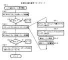
図4は、本発明の動作説明フローチャート(生成)を示す。これは、図2の画面および左下のサブ画面を用いて関係オブジェクトを生成するときの手順を示したものである。
【0028】
図4において、S1は、アイコンをクリックする。
S2は、処理メニューを表示する。これは、S1のアイコンのクリックに対応して、処理メニュー(ここでは、関係付け処理を含む処理メニュー)を表示する。
【0029】
S3は、関係付けが選択されたか判別する。これは、S2で表示した処理メニュー上で関係付けの処理が選択されたか判別する。YESの場合には、S4に進む。NOの場合には、選択された他の処理を実行する。
【0030】
S4は、関係付け先を選択する。これは、図2の画面の上段の例えば▲1▼のハブ12のアイコンと、▲2▼のマシン13のアイコンとをクリックし、関係オブジェクトを作成する管理対象をそれぞれ選択する。
【0031】
S5は、関係情報の追加画面を表示する。これは、図2の左下のサブ画面上にS4で選択した2つの管理対象(ここでは、▲1▼のハブ12のアイコンと、▲2▼のマシン13のアイコン)を表示、および依存関係を指定する下記の情報を表示する。
【0032】
・右で異常発生時の左への影響
・重大
・軽微
・影響無
・左で異常発生時の右への影響
・重大
・軽微
・影響無
S6は、依存関係を選択する。これは、S5で図2の左下のサブ画面上に表示された上記2つの方向(左→右、左←右)について、ここでは右側に記載したように、
・左→右:重大
・左←右:影響無
を選択する。
【0033】
S7は、ハブーマシンクラスのインスタンスを生成する。これにより、後述する図10の(c)のハブーマシンのインスタンス(関係オブジェクト9)が作成されたこととなる。
【0034】
以上のように、図2の画面上で処理メニューから関係付け処理を選択した後、関係付けする管理対象(例えば図2の▲1▼のハブと、▲2▼のマシン)を選択し図2の左下のサブ画面を表示し、サブ画面上で依存関係を選択(ここでは、左→右:重大、左←右:影響無)すると、自動的に関係オブジェクト9として後述する図10の(c)の関係オブジェクト9を生成することが可能となる。
【0035】
図5は、本発明の動作説明フローチャート(追加)を示す。これは、管理対象の追加に伴い関係オブジェクト9を自動生成するときの手順を示したものである。
【0036】
図5において、S11は、ノードの追加のルールを実行開始する。
S12は、同じMacアドレスを持つハブを検索する。これは、ノードとして例えば図2のマシン15を追加しようとした場合に、当該ノードである図2のマシン15のMacアドレスと等しいMacアドレスを持つハブを探すと、ここでは、当該マシン15が直接に接続しているハブ14のポートに同一のMacアドレスが保持されているので、ここでは、有りとなる。
【0037】
S13は、ありか判別する。ここでは、図2のマシン15のMacアドレスと同一のMacアドレスをハブ14が持っていると判明したので、YESとなり、S14でハブーマシンクラスのインスタンス(後述する図10の(c)の関係オブジェクト9)を、S21からS24の手順により自動生成する。
【0038】
S21は、オブジェクトID1にハブのオブジェクトID=02を代入する。これにより、図10の(c)の関係オブジェクト9のオブジェクトID1(親)の欄に、図2の親であるハブ14のオブジェクトID=02が代入されて登録されたこととなる。
【0039】
S22は、オブジェクトID2にマシンのオブジェクトID=03を代入する。これにより、図10の(c)の関係オブジェクト9のオブジェクトID2(子)の欄に、図2の子であるマシン15のオブジェクトID=03が代入されて登録されたこととなる。
【0040】
S23は、依存1→2に重大を代入する。これは、例えば後述する図8のハブーマシンのインスタンス(関係オブジェクト9)を自動作成するルールに従い、依存1→2に重大、即ち図2の親のハブ14から子のマシン15への依存関係が重大であるということを、図10の(c)の「依存1→2」の欄に図示のように代入する。
【0041】
S24は、依存2→1に影響無を代入する。これは、例えば後述する図8のハブーマシンのインスタンス(関係オブジェクト9)を自動作成するルールに従い、依存2→1に影響無、即ち図2の子のマシン15から親のハブ14への依存関係が影響無であるということを、図10の(c)の「依存2→1」の欄に図示のように代入する。
【0042】
以上によって、管理対象(ルータ、ハブ、マシンなど)が追加されたときに、該当するルール(例えばハブにマシンが追加接続された場合には、後述する図8のルール)に従い追加された管理対象と他の管理対象と間の依存関係を登録する関係オブジェクト9を自動生成することが可能となる。
【0043】
図6は、本発明の動作説明フローチャート(生成)を示す。
図6において、S31は、他の処理で検出された管理オブジェクトを作成する。これは、ネットワークに例えば追加されて検出された管理対象の構成情報を登録した管理オブジェクト8(例えば図10の(a)あるいは(b)の管理オブジェクト)を作成する。
【0044】
S32は、追加情報を受信する。これは、関係オブジェクト9を作成するために必要な追加情報(Macアドレスなど)を管理対象中に配置したエージェントから受信する。
【0045】
S33は、クラスを判別する。これは、検出された管理対象と依存関係を作成する管理対象とのクラスを判別する。
S34は、ルールを検索する。これは、S33で判別したクラスに適用するルール(例えばハブとマシンというクラスに適用する図8のルール)を検索する。
【0046】
S35は、ルールを実行する。これは、S34で適用するルールを検索してみ付け、当該見つけたルールに従い関係オブジェクト(例えば図8のルールに従い図10の(c)の関係オブジェクト9)を自動作成する。そして、S34、S35を繰り返し、全ての関係オブジェクト9を作成する。
【0047】
以上によって、管理オブジェクト8が検出されると、当該管理オブジェクト8に対応する管理対象と直接に接続されている他の管理対象(管理オブジェクト8に対応する管理対象)との間の依存関係を関係オブジェクト9として該当ルールを適用して自動生成することが可能となる。
【0048】
図7は、本発明のクラス構造例を示す。ここでは、図示のように左側から
・Hubクラス:
・Object ID
・Port No[ ]
・MAC Address[ ]
・Hub−MachineRelクラス:
・Object ID1
・Object ID2
・Dependency(依存関係)
・Machineクラス:
・Object ID
・MAC Address[ ]
・・・
という内容を少なくともそれぞれ登録するようにしている。ここで、記述した各内容は、図7の下段に示す通りである。
【0049】
以上のように、クラス構造で表現し、HubクラスのインスタンスおよびMachineクラスのインスタンスを既述した管理オブジェクト8として分かり易く記述(例えば図10の(a),(b)参照)し、Hub−MachineRelクラスのインスタンスを関係オブジェクト9として記述(図10の(c)参照)している。
【0050】
図8は、本発明の関係生成ルール例を示す。このルールは、ハブとマシンとの間の関係オブジェクト9を自動生成するためのルールである。先頭の2行の
・対象となる管理オブジェクトのクラス1:Hubクラス
・対象となる管理オブジェクトのクラス2:Machineクラス
によって、Hubクラスと、Machineクラスとの関係オブジェクト9の生成ルールである旨を定義している(他のクラス間の定義も同様である)。
【0051】
次に、条件である
・クラス1のMAC Address属性とクラス2のMAC Address属性が等しい
という条件に合致するときに、Hub−MachineRelクラスを生成する。生成する関係オブジェクトの属性は。
【0052】
・Dependency属性←クラス2のインスタンスはクラス1のインスタンスに依存する
・Dependency属性←クラス1のインスタンスはクラス2のインスタンスに影響無
と登録する。
【0053】
以上の図8のルールに従い、ハブとマシンとが接続されたときの関係オブジェクト9である、例えば図10の(c)の関係オブジェクト9を自動作成することが可能となる。
【0054】
図9は、本発明の動作説明フローチャートを示す。
図9において、S41は、ハブの追加のルール実行開始する。
S42は、同じMacアドレスを持つハブを検索する。これは、例えば図2のハブ14が追加されたときに当該ハブ14のMACアドレスと同一のMacアドレスを持つハブ、ここでは、直ぐ上位の▲1▼のハブを見つける(▲1▼のハブの管理オブジェクト8中のポートのいずれかに追加したハブ14のMACアドレスと同一のものを見つける)。
【0055】
S43は、ありか判別する。YESの場合には、S44に進む。NOの場合には、同一のMACアドレスが見つからなくかったので終了する。
S44は、ハブーハブクラスのインスタンスを生成する。これは、ハブとハブとの依存関係を登録した関係オブジェクト9を、S51からS54の手順により生成する。
【0056】
S51は、オブジェクトID1(親)にハブのオブジェクトIDを代入する。これにより、図10の(c)の関係オブジェクト9と同様の、ハブーハブのインスタンス(関係オブジェクト9)のオブジェクトID1(親)の欄に、親のハブのオブジェクトIDが代入されて登録されたこととなる。
【0057】
S52は、オブジェクトID2(子)にハブのオブジェクトIDを代入する。これにより、図10の(c)の関係オブジェクト9と同様の、ハブーハブのインスタンス(関係オブジェクト9)のオブジェクトID2(子)の欄に、子のハブのオブジェクトIDが代入されて登録されたこととなる。
【0058】
S53は、依存1→2に重大を代入する。これは、例えば後述する図8のハブーマシンのインスタンス(関係オブジェクト9)を自動作成するルールと同様の、ハブーハブのインスタンス(関係オブジェクト9)を生成するルールに従い、依存1→2に重大、即ち親のハブから子のハブへの依存関係が重大であるということを、図10の(c)の「依存1→2」の欄と同様に、図示のように代入する。
【0059】
S54は、依存2→1に影響無を代入する。これは、同様に、子のハブから親のハブへの依存関係が影響無であるということを、図10の(c)の「依存2→1」の欄と同様に、図示のように代入する。これらS51から54によって、管理対象(ハブ)に管理対象(ハブ)が追加されたときに、該当するルールに従い追加された管理対象(ハブ)と他の管理対象(ハブ)と間の依存関係を登録する関係オブジェクト9を自動生成することが可能となる。
【0060】
S45は、同じMacアドレスXを持つマシンを検索する。
S46は、ありか判別する。YESの場合には、S47に進む。NOの場合には終了する。
【0061】
S47は、ハブーマシンのインスタンス(関係オブジェクト9)を既述した図5のS21からS24と同様にして生成する(図10の(c)参照)。
以上によって、図2のハブ14およびマシン15が追加されたときに当該追加されたハブ14とマシン15の構成情報を登録した管理オブジェクト8をもとに、S41からS47によってハブーハブの間の依存関係、およびハブーマシンの間の依存関係をそれぞれの関係オブジェクト9に自動的に登録することが可能となる。
【0062】
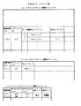
図10は、本発明のインスタンス例を示す。
図10の(a)は、ハブのインスタンス(管理オブジェクト8)の例を示す。
ハブのインスタンス(管理オブジェクト8)は、図示の下記の構成情報を登録したものである。
【0063】
・管理対象ID:ハブ0
・オブジェクトID:02
・ポート毎に接続先Macアドレスあるいは自Macアドレス
以上のように、ハブの管理オブジェクト8にポート毎に接続先の管理対象(ハブ、ルータ、マシンなど)のMacアドレスを当該ハブが持つ機能により自動登録(学習)することにより、既述した図5、図9などのときに接続先の管理対象のMacアドレスと一致するときは相互に接続されていることを自動的に検索し、相互の間の依存関係を登録した関係オブジェクト9を自動生成することが可能となる。
【0064】
図10の(b)は、マシンのインスタンス(管理オブジェクト8)の例を示す。マシンのインスタンス(管理オブジェクト8)は、図示の下記の構成情報を登録したものである。
【0065】
・管理対象ID:マシン0
・オブジェクトID:03
・Macアドレス:Mac1
以上のように、マシンの管理オブジェクト8にオブジェクトIDおよびMacアドレスを登録することにより、既述した図5、図9などのときに当該Macアドレスをもとに、接続先のハブなどの管理対象のMacアドレスと一致するときは相互に接続されていることを自動的に検索などし、相互の間の依存関係を登録した関係オブジェクト9を自動生成することが可能となる。
【0066】
図10の(c)は、ハブーマシンのインスタンス(関係オブジェクト9)の例を示す。これは、図10の(a)と(b)の間の依存関係を登録した関係オブジェクト9であって、図示の下記の情報を登録したものである。
【0067】
・管理対象:ハブーマシン0
・オブジェクトID1(親):02(親となる管理対象のオブジェクトID)
・オブジェクトID1(子):03(子となる管理対象のオブジェクトID)
・依存1→2(親から子への依存関係):重大
・依存2→1(子から親への依存関係):影響無
以上のように、親から子への依存関係、および子から親への依存関係をルールに従い自動登録することにより、後述する図11および図12を用いて説明するように、障害イベントが管理対象中のエージェント21から図1のサーバ1に通知されたときに、依存関係をもとに影響のあるイベントを抑止し、障害の根本原因となった管理対象のみを図2の画面上で点滅などして管理者に知らせることが可能となる。
【0068】
図11は、本発明の監視フローチャートを示す。
図11において、S61は、エージェントからのイベントを受信する。これは、管理対象中に配置してあるエージェント21から自身の管理対象の障害などの情報を設定したイベント(例えばSNMPトラップなどのイベント)を、図1のサーバ1を構成するイベント収集手段5が受信する。
【0069】
S62は、関係オブジェクト8を検索して、関係する管理オブジェクトを調べる。これは、S62で受信した障害イベントに設定されている管理対象(オブジェクトIDなど)が登録されている例えば既述した図10の(c)の関係オブジェクト9があるかを調べる。
【0070】
S63は、関係する管理オブジェクト8のイベントを調べる。
S64は、ありか判別する。YESの場合には、該当するイベントの抑止フラグを後述する図12のイベントテーブル10中の該当するイベントにたてる。NOの場合には、終了する。
【0071】
以上によって、S61で受信した障害イベントに設定されている管理対象(オブジェクトIDなど)が登録されている図10の(c)のような関係オブジェクト9が見つかった場合に、当該関係オブジェクト9に設定されている依存関係をもとに該当する管理オブジェクトの設定されているイベントが既に図12のイベントテーブル10に設定されていたときは抑止フラグをたてて非警告表示にする。ここで、S62で受信したイベントに設定されている管理対象が登録されている関係オブジェクト9中の依存関係が重大となっている接続方向の管理対象のイベントが既に図12のイベントテーブル10に受信して登録されているときには抑止フラグをたてて警告表示しないようにし、障害通知されるイベント中から根本原因となるイベントだけを警告表示することが可能となる。
【0072】
図12は、本発明のイベントテーブル例を示す。このイベントテーブル10は、ネットワークに接続された管理対象中のエージェント21から送信されたイベントを順次登録したものであって、イベントの登録時などに既述した図11のフローチャートに従い受信したイベントに設定されている管理オブジェクトの登録されている関係オブジェクト9をもとに、影響を受けた方の管理オブジェクトのイベントの抑止フラグをたてて非警告表示にするようにしている。そして、抑止フラグのたっていない管理対象(管理オブジェクト)のマークを図2の画面上で点滅などすることにより、原因元となった管理対象のマークのみを点滅などして管理者に障害発生を通知することが可能となる。
【0073】
【発明の効果】
以上説明したように、本発明によれば、ネットワークに接続された管理対象を管理する管理オブジェクト8および管理対象間の依存関係を管理する関係オブジェクト9を設け、管理対象の動的な追加、変更などを行なうと共に障害イベントをもとに障害発生元を特定して表示などする構成を採用しているため、動的に構成が変更、追加などするような分散ネットワークシステムにおいても、管理対象(ルータ、ハブ、マシンなど)から通知されるイベントの中から根本原因となるイベントだけを確実に選別して表示などし、管理者に通知することが可能となる。
【図面の簡単な説明】
【図1】本発明のシステム構成図である。
【図2】本発明の画面例である。
【図3】本発明のオブジェクト説明図である。
【図4】本発明の動作説明フローチャート(生成)である。
【図5】本発明の動作説明フローチャート(追加)である。
【図6】本発明の動作説明フローチャート(生成)である。
【図7】本発明のクラス構造例である。
【図8】本発明の関係生成ルール例である。
【図9】本発明の動作説明フローチャートである。
【図10】本発明のインスタンス例である。
【図11】本発明の監視フローチャートである。
【図12】本発明のイベントテーブル例である。
【符号の説明】
1:サーバ
2:関係情報生成手段
3:構成情報収集手段
4:イベント相関手段
5:イベント収集手段
6:関係情報生成ルール
7:オブジェクトDB
8:管理オブジェクト
9:関係オブジェクト
10:イベントテーブル
11:ルータ
12、14:ハブ
13、15:マシン(コンピュータシステム)
21:エージェント[0001]
[Industrial application fields]
The present invention relates to a network management apparatus and a recording medium for monitoring a management target connected to a network.
[0002]
[Prior art]
Conventionally, when performing failure management of a distributed network system, a program called an agent that monitors a management target such as a computer connected to a network, a network device (router, hub, etc.) and software is arranged from the agent. Configuration information collected by the management server and displayed as a map. When a failure occurs, the management server receives a failure event such as an SNMP trap issued by the agent, and the configuration information corresponding to the management target in which the failure event has occurred The icon was blinked to notify the administrator that a failure occurred.
[0003]
[Problems to be solved by the invention]
For this reason, when a large number of management targets (routers, hubs, computers, software, etc.) are connected to the network, a failure that occurred in one management target has spread to other management targets, resulting in a large number of management targets. It is difficult to determine which is the root cause of the failure by flashing the icon of the configuration information corresponding to, and it is necessary to identify which management target is the failure source by making full use of specialized knowledge. There was a problem that could not be dealt with.
[0004]
Also, because the management target of the network configuration and connected devices (devices such as routers, hubs, and PCs) changes dynamically, it is possible to dynamically cope with this and automatically identify the failure source. It is desired.
[0005]
In order to solve these problems, the present invention provides a management object for managing a management target connected to a network and a relation object for managing a dependency relationship between management targets, and dynamically adding or changing a management target. The purpose is to identify the source of the failure based on the event.
[0006]
[Means for Solving the Problems]
Means for solving the problem will be described with reference to FIG.
In FIG. 1, a
[0007]
The relationship information generation unit 2 generates relationship information between management targets.
The
The event collecting unit 5 collects events from the management target.
[0008]
The relationship information generation rule 6 is a rule for automatically generating relationship information between management targets.
The
[0009]
The
Next, the operation will be described.
The event collecting means 5 receives and collects the events transmitted from the managed
[0010]
At this time, when there is a notification of change or addition of the management target, the
[0011]
In addition, the
[0012]
Therefore, the
[0013]
【Example】
Next, embodiments and operations of the present invention will be described in detail sequentially with reference to FIGS.
[0014]
FIG. 1 shows a system configuration diagram of the present invention.
In FIG. 1, a
[0015]
The relationship information generating means 2 generates relationship information such as dependency relationships between management targets (for example, routers, hubs, machines, etc.), and further stores them in the
[0016]
The configuration information collecting unit 3 collects configuration information of a management target connected to the network, and further registers the collected configuration information in the
[0017]
The
[0018]
The event collecting means 5 collects events transmitted from the
The relationship information generation rule 6 is a rule for automatically generating relationship information between managed objects (see FIG. 8).
[0019]
The object DB 7 registers and manages objects. Here, the
[0020]
The
The
[0021]
The event table 10 receives and stores events transmitted from the managed
[0022]
FIG. 2 shows an example screen of the present invention. Here, the upper screen displays the illustrated
[0023]
The lower left screen shows a sub screen for instructing a dependency relationship between management targets. Here, (1) hub 12 and (2) machine 13 indicated by dotted arrows are sequentially clicked to select a management target and displayed as icons on the left and right on the illustrated sub screen, respectively. Next, in the upper part of the sub-screen, "Right impact on the left when an error occurs"
・ Major
・ Mild
・ No effect
Select one of these (in this case, select no effect). Similarly, in the lower part of the sub-screen, “Left has an effect on the right when an error occurs”
・ Major
・ Mild
・ No effect
Select one of these (in this case, select critical). By selecting as shown on the illustrated sub-screen, registration is performed as shown in the hub-machine instance (related object 8) of FIG. 10C to be described later, and the machine is started from the hub 12 on the upper screen of FIG. It is possible to display a solid line arrow (3) to 13.
[0024]
As described above, the management target connected to the network is displayed as an icon on the screen of FIG. 2 based on the configuration information in the
[0025]
The
FIG. 3 shows an object explanatory diagram of the present invention. This shows a state in which the management object and the dependency relationship in the left half on the screen of FIG. The dotted lines indicate the
[0026]
As described above, for the management target (router, hub, machine, etc.) connected to the network, the configuration information is registered in the
[0027]
FIG. 4 shows an operation explanation flowchart (generation) of the present invention. This shows a procedure for generating a related object using the screen of FIG. 2 and the lower left sub-screen.
[0028]
In FIG. 4, S1 clicks an icon.
S2 displays a processing menu. This displays a process menu (here, a process menu including an association process) in response to the click of the icon of S1.
[0029]
In S3, it is determined whether or not the association is selected. This is to determine whether the association process is selected on the process menu displayed in S2. If YES, the process proceeds to S4. In the case of NO, the other selected process is executed.
[0030]
In S4, an association destination is selected. For example, the hub 12 icon (1) and the machine 13 icon (2) at the top of the screen in FIG. 2 are clicked to select management targets for creating related objects.
[0031]
In step S5, a related information addition screen is displayed. This is because the two management objects selected in S4 (here, the icon of the hub 12 of (1) and the icon of the machine 13 of (2)) are displayed on the sub-screen at the lower left of FIG. Displays the following information to be specified.
[0032]
・ Effect on the left when an abnormality occurs on the right
・ Major
・ Minor
・ No effect
・ Effect on the right when an abnormality occurs on the left
・ Major
・ Minor
・ No effect
S6 selects a dependency relationship. This is because the two directions (left → right, left ← right) displayed on the lower left sub-screen in FIG.
・ Left → Right: Serious
・ Left ← Right: No effect
Select.
[0033]
In step S7, an instance of the hub machine class is generated. As a result, an instance (relation object 9) of the hub machine in FIG. 10C to be described later is created.
[0034]
As described above, after selecting the association process from the process menu on the screen of FIG. 2, the management objects to be related (for example, the hub of (1) in FIG. 2 and the machine of (2)) are selected. When the dependency is selected on the sub-screen (here, left → right: serious, left ← right: unaffected), the
[0035]
FIG. 5 shows a flowchart (addition) for explaining the operation of the present invention. This shows a procedure for automatically generating the
[0036]
In FIG. 5, S11 starts executing the node addition rule.
S12 searches for a hub having the same Mac address. For example, when a machine 15 in FIG. 2 is added as a node and a hub having a Mac address equal to the Mac address of the machine 15 in FIG. Since the same Mac address is held in the port of the
[0037]
In S13, it is determined whether or not there is. Here, since it has been found that the
[0038]
In S21, the hub object ID = 02 is assigned to the object ID1. As a result, the object ID = 02 of the
[0039]
In S22, the machine object ID = 03 is assigned to the object ID2. As a result, the object ID = 03 of the machine 15 that is the child of FIG. 2 is substituted and registered in the object ID2 (child) column of the
[0040]
In S23, seriousness is assigned to the
[0041]
S24 substitutes no influence for dependency 2 → 1. This is, for example, in accordance with a rule for automatically creating an instance (relation object 9) of the hub machine shown in FIG. 8 to be described later. The fact that there is no influence is substituted in the “dependency 2 → 1” column of FIG.
[0042]
As described above, when a management target (router, hub, machine, etc.) is added, the management target added according to the corresponding rule (for example, the rule of FIG. 8 described later when a machine is additionally connected to the hub). It is possible to automatically generate a
[0043]
FIG. 6 shows an operation explanation flowchart (generation) of the present invention.
In FIG. 6, S31 creates a management object detected by other processing. This creates, for example, a management object 8 (for example, the management object (a) or (b) of FIG. 10) in which the configuration information of the management target added and detected in the network is registered.
[0044]
S32 receives additional information. This receives additional information (such as a Mac address) necessary to create the
[0045]
In S33, the class is determined. This discriminates the class of the detected management target and the management target for creating the dependency.
S34 searches for a rule. This searches for a rule applied to the class determined in S33 (for example, the rule of FIG. 8 applied to the class of hub and machine).
[0046]
In S35, the rule is executed. This is done by searching for a rule to be applied in S34 and automatically creating a related object (for example, the
[0047]
As described above, when the
[0048]
FIG. 7 shows an example class structure of the present invention. Here, from the left as shown
・ Hub class:
・ Object ID
・ Port No []
・ MAC Address []
-Hub-MachineRel class:
・ Object ID1
・ Object ID2
・ Dependency
・ Machine class:
・ Object ID
・ MAC Address []
...
At least each content is registered. Here, the described contents are as shown in the lower part of FIG.
[0049]
As described above, it is expressed by a class structure, and an instance of the Hub class and an instance of the Machine class are described in an easy-to-understand manner as the
[0050]
FIG. 8 shows an example of the relationship generation rule of the present invention. This rule is a rule for automatically generating the
-Target managed object class 1: Hub class
-Target managed object class 2: Machine class
Defines that it is a generation rule of the
[0051]
Next is the condition
-
When the above condition is met, a Hub-MachineRel class is generated. What are the attributes of the relationship object to generate
[0052]
Dependency attribute ← Class 2 instance depends on
Dependency attribute ←
And register.
[0053]
In accordance with the rules of FIG. 8, it is possible to automatically create, for example, the
[0054]
FIG. 9 shows a flowchart for explaining the operation of the present invention.
In FIG. 9, S41 starts execution of an additional rule for the hub.
S42 searches for a hub having the same Mac address. For example, when the
[0055]
In S43, it is determined whether or not there is. If YES, the process proceeds to S44. In the case of NO, since the same MAC address was not found, the process ends.
In S44, an instance of the hub-hub class is generated. In this process, the
[0056]
In S51, the object ID of the hub is assigned to the object ID 1 (parent). As a result, similar to the
[0057]
In S52, the object ID of the hub is substituted for object ID2 (child). As a result, similar to the
[0058]
S53 assigns seriousness to the
[0059]
In S54, no influence is substituted for dependency 2 → 1. Similarly, in the same way as in the “dependency 2 → 1” column of FIG. 10C, the fact that the dependency from the child hub to the parent hub is not affected is substituted as shown in the figure. To do. When the management target (hub) is added to the management target (hub) through S51 to S54, the dependency relationship between the management target (hub) added according to the corresponding rule and the other management target (hub) is determined. It becomes possible to automatically generate the
[0060]
S45 searches for machines having the same Mac address X.
In S46, it is determined whether or not there is. If YES, the process proceeds to S47. If NO, the process ends.
[0061]
In S47, an instance of the hub machine (related object 9) is generated in the same manner as S21 to S24 in FIG. 5 described above (see FIG. 10C).
As described above, when the
[0062]
FIG. 10 shows an example instance of the present invention.
FIG. 10A shows an example of a hub instance (management object 8).
The instance of the hub (management object 8) is obtained by registering the following configuration information shown in the figure.
[0063]
-Management target ID:
Object ID: 02
-Connection destination Mac address or own Mac address for each port
As described above, by automatically registering (learning) the Mac address of the management target (hub, router, machine, etc.) of the connection destination for each port in the
[0064]
FIG. 10B shows an example of a machine instance (management object 8). The machine instance (management object 8) is obtained by registering the configuration information shown below.
[0065]
-Management target ID:
Object ID: 03
-Mac address: Mac1
As described above, by registering the object ID and the Mac address in the
[0066]
FIG. 10C shows an example of an instance of the hub machine (related object 9). This is a
[0067]
-Management target:
Object ID 1 (parent): 02 (parent managed object ID)
Object ID1 (child): 03 (object ID of child management target)
Dependency 2 → 1 (dependence from child to parent): No effect
As described above, by automatically registering the dependency relationship from the parent to the child and the dependency relationship from the child to the parent according to the rule, the failure event is managed as described later with reference to FIGS. 1 is notified to the
[0068]
FIG. 11 shows a monitoring flowchart of the present invention.
In FIG. 11, S61 receives an event from an agent. This is because the event collection means 5 constituting the
[0069]
In step S62, the
[0070]
In S63, the event of the
In S64, it is determined whether or not there is. In the case of YES, the suppression flag of the corresponding event is set to the corresponding event in the event table 10 of FIG. If NO, the process ends.
[0071]
As described above, when the
[0072]
FIG. 12 shows an example of an event table of the present invention. This event table 10 sequentially registers events transmitted from the managed
[0073]
【The invention's effect】
As described above, according to the present invention, the
[Brief description of the drawings]
FIG. 1 is a system configuration diagram of the present invention.
FIG. 2 is a screen example of the present invention.
FIG. 3 is an object explanatory diagram of the present invention.
FIG. 4 is a flowchart for explaining the operation of the present invention (generation).
FIG. 5 is an operation explanation flowchart (addition) of the present invention.
FIG. 6 is an operation explanation flowchart (generation) of the present invention.
FIG. 7 is an example of a class structure of the present invention.
FIG. 8 is an example of a relationship generation rule of the present invention.
FIG. 9 is a flowchart illustrating the operation of the present invention.
FIG. 10 is an example instance of the present invention.
FIG. 11 is a monitoring flowchart of the present invention.
FIG. 12 is an example of an event table according to the present invention.
[Explanation of symbols]
1: Server
2: Relationship information generation means
3: Configuration information collection means
4: Event correlation means
5: Event collection means
6: Relation information generation rule
7: Object DB
8: Managed object
9: Relationship object
10: Event table
11: Router
12, 14: Hub
13, 15: Machine (computer system)
21: Agent
Claims (3)
Translated fromJapaneseネットワークに新たに接続された管理対象を一意に識別する識別情報に基づき、該新たな管理対象と直接に接続されている他の管理対象を前記ネットワークを探索して検索する手段と、
管理対象の間の依存関係を登録する関係オブジェクトを自動生成するために、該関係オブジェクトに登録すべき内容を前記ネットワーク管理装置内に予め設定、記憶した関係生成ルールを参照し、前記新たな管理対象と前記他の管理対象とに関する関係オブジェクトに登録すべき情報を該関係生成ルールから抽出し、該新たな管理対象と該他の管理対象との依存関係に関する関係オブジェクトを生成する手段と
を備えたことを特徴とするネットワーク管理装置。In a network management device that monitors management targets connected to the network,
Meansfor searching the network for other management targets directly connected to the new management target based on identification information for uniquely identifying the management target newly connected to thenetwork ;
In order to automatically generate a relation object for registering a dependency relationship between management targets, the contents to be registered in the relation object are setand stored in advancein the network management device, and the new management is performed. Means forextracting information to be registered in a relation object relating to a target and the other management targetfrom the relation generation rule, and generating a relation object relating to a dependency relationship between the new management target and the other management target A network management device characterized by that.
管理対象からのイベントを受信する手段と、
前記イベントが発生した管理対象に関する、管理対象の間の依存関係を登録する関係オブジェクトが存在するか否かを前記ネットワークを探索して検索する手段と、
検索した関係オブジェクトを参照して、前記イベントが発生した管理対象に依存関係のある他の管理対象があるかを調べる調査手段と、
前記調査手段によって調べられた他の管理対象からのイベントを抑止する手段と
を備えたことを特徴とするネットワーク管理装置。In a network management device that monitors management targets connected to the network,
Means for receiving events from managed objects;
Meansfor searching the network to find out whether there is a relationship object for registering a dependency relationship between the management targets regarding the management target in which the event has occurred;
Aninvestigation means for referring to the retrieved relationship object and checkingwhether there is another management target having a dependency relationship with the management target in which the event has occurred;
A network management apparatus comprising: means for suppressing an event from another management objectchecked by the checking means .
ネットワークに新たに接続された管理対象を一意に識別する識別情報に基づき、該新たな管理対象と直接に接続されている他の管理対象を前記ネットワークを探索して検索する手段と、
管理対象の間の依存関係を登録する関係オブジェクトを自動生成するために、該関係オブジェクトに登録すべき内容を前記ネットワーク管理装置内に予め設定、記憶した関係生成ルールを参照し、前記新たな管理対象と前記他の管理対象とに関する関係オブジェクトに登録すべき情報を該関係生成ルールから抽出し、該新たな管理対象と該他の管理対象との依存関係に関する関係オブジェクトを生成する手段と
して機能させるためのプログラムを記録したコンピュータ読取可能な記録媒体。Computer
Meansfor searching the network for other management targets directly connected to the new management target based on identification information for uniquely identifying the management target newly connected to thenetwork ;
In order to automatically generate a relation object for registering a dependency relationship between management targets, the contents to be registered in the relation object are setand stored in advancein the network management device, and the new management is performed. Information to be registered in a relation object related to a target and the other management target isextracted from the relation generation rule, and functions as a means for generating a relation object related to the dependency between the new management target and the other management target A computer-readable recording medium on which a program for recording is recorded.
Priority Applications (2)
| Application Number | Priority Date | Filing Date | Title |
|---|---|---|---|
| JP30636599AJP3875436B2 (en) | 1999-10-28 | 1999-10-28 | Network management apparatus and recording medium |
| US09/671,008US6990601B1 (en) | 1999-10-28 | 2000-09-27 | Apparatus and method for managing network and computer-readable recording medium thereof |
Applications Claiming Priority (1)
| Application Number | Priority Date | Filing Date | Title |
|---|---|---|---|
| JP30636599AJP3875436B2 (en) | 1999-10-28 | 1999-10-28 | Network management apparatus and recording medium |
Publications (2)
| Publication Number | Publication Date |
|---|---|
| JP2001125854A JP2001125854A (en) | 2001-05-11 |
| JP3875436B2true JP3875436B2 (en) | 2007-01-31 |
Family
ID=17956188
Family Applications (1)
| Application Number | Title | Priority Date | Filing Date |
|---|---|---|---|
| JP30636599AExpired - Fee RelatedJP3875436B2 (en) | 1999-10-28 | 1999-10-28 | Network management apparatus and recording medium |
Country Status (2)
| Country | Link |
|---|---|
| US (1) | US6990601B1 (en) |
| JP (1) | JP3875436B2 (en) |
Families Citing this family (76)
| Publication number | Priority date | Publication date | Assignee | Title |
|---|---|---|---|---|
| CA2305808A1 (en)* | 1997-10-02 | 1999-04-15 | Sankyo Company Limited | Amidocarboxylic acid derivatives |
| US7203954B1 (en)* | 2000-10-11 | 2007-04-10 | Sony Corporation | IP address discovery for cable modem in set-top box |
| US7054901B2 (en) | 2001-05-31 | 2006-05-30 | Juniper Networks, Inc. | Network management interface with selective rendering of output |
| US7072946B2 (en) | 2001-05-31 | 2006-07-04 | Juniper Networks, Inc. | Network router management interface with API invoked via login stream |
| US7111206B1 (en) | 2001-09-19 | 2006-09-19 | Juniper Networks, Inc. | Diagnosis of network fault conditions |
| US7441018B1 (en) | 2001-09-19 | 2008-10-21 | Juniper Networks, Inc. | Identification of applied configuration information |
| JP4796251B2 (en)* | 2001-09-21 | 2011-10-19 | 株式会社日立製作所 | Network storage system and control method thereof |
| US7849171B2 (en) | 2002-02-27 | 2010-12-07 | Ricoh Co. Ltd. | Method and apparatus for monitoring remote devices by creating device objects for the monitored devices |
| US7181694B2 (en)* | 2002-05-31 | 2007-02-20 | Sap Aktiengesellschaft | Software customization objects for programming extensions associated with a computer system |
| US20030222903A1 (en)* | 2002-05-31 | 2003-12-04 | Wolfgang Herzog | Distributing customized computer settings to affected systems |
| US7334222B2 (en) | 2002-09-11 | 2008-02-19 | International Business Machines Corporation | Methods and apparatus for dependency-based impact simulation and vulnerability analysis |
| JP3862652B2 (en)* | 2002-12-10 | 2006-12-27 | キヤノン株式会社 | Printing control method and information processing apparatus |
| US20040155899A1 (en)* | 2003-02-11 | 2004-08-12 | Conrad Jeffrey Richard | Method and system for presenting an arrangement of management devices operable in a managed network |
| US7555545B2 (en)* | 2003-07-30 | 2009-06-30 | AT&T Intellectual Property, I,L.P | Method system and storage medium for detecting network elements |
| US7475401B1 (en) | 2003-12-30 | 2009-01-06 | Sap Ag | Filtered unified logging service |
| US8166152B1 (en)* | 2003-12-30 | 2012-04-24 | Sap Ag | Architecture and method for monitoring system resources within an enterprise network |
| US7493624B1 (en) | 2003-12-30 | 2009-02-17 | Sap Ag | Management architecture and method employed within a clustered node configuration |
| US7941521B1 (en) | 2003-12-30 | 2011-05-10 | Sap Ag | Multi-service management architecture employed within a clustered node configuration |
| US7739374B1 (en) | 2003-12-30 | 2010-06-15 | Sap Ag | System and method for configuring tracing and logging functions |
| US7725572B1 (en)* | 2003-12-30 | 2010-05-25 | Sap Ag | Notification architecture and method employed within a clustered node configuration |
| US7822826B1 (en) | 2003-12-30 | 2010-10-26 | Sap Ag | Deployment of a web service |
| US7756968B1 (en) | 2003-12-30 | 2010-07-13 | Sap Ag | Method and system for employing a hierarchical monitor tree for monitoring system resources in a data processing environment |
| US7721266B2 (en)* | 2004-03-26 | 2010-05-18 | Sap Ag | Unified logging service with a logging formatter |
| US7526550B2 (en)* | 2004-03-26 | 2009-04-28 | Sap Ag | Unified logging service with a log viewer |
| US7774369B2 (en)* | 2004-07-07 | 2010-08-10 | Sap Aktiengesellschaft | Configuring computer systems with business configuration information |
| US7735063B2 (en) | 2004-07-07 | 2010-06-08 | Sap Aktiengesellschaft | Providing customizable configuration data in computer systems |
| JP2006031109A (en)* | 2004-07-12 | 2006-02-02 | Ntt Docomo Inc | Management system and management method |
| US7788226B2 (en)* | 2004-12-30 | 2010-08-31 | Sap Ag | Monitoring availability of applications |
| US7810075B2 (en)* | 2005-04-29 | 2010-10-05 | Sap Ag | Common trace files |
| US8635596B2 (en) | 2006-04-21 | 2014-01-21 | Microsoft Corporation | Model-based event processing |
| US7505983B2 (en)* | 2006-06-26 | 2009-03-17 | Sap Ag | Extending data flows |
| US20080229153A1 (en)* | 2007-03-13 | 2008-09-18 | At&T Knowledge Ventures, Lp | System and method of network error analysis |
| US8484327B2 (en)* | 2007-11-07 | 2013-07-09 | Mcafee, Inc. | Method and system for generic real time management of devices on computers connected to a network |
| JP5239072B2 (en)* | 2008-01-18 | 2013-07-17 | インターナショナル・ビジネス・マシーンズ・コーポレーション | Computer system, method and computer program for managing components |
| JP5243804B2 (en) | 2008-01-21 | 2013-07-24 | インターナショナル・ビジネス・マシーンズ・コーポレーション | Computer system, method and computer program for managing components |
| US10073708B2 (en)* | 2008-03-14 | 2018-09-11 | S-Printing Solution Co., Ltd | System and method of providing visual indicators to manage peripheral devices |
| US20100037169A1 (en)* | 2008-08-08 | 2010-02-11 | Eastman Kodak Company | Display of system operating status in a multi-node system |
| JP5132779B2 (en)* | 2008-10-30 | 2013-01-30 | インターナショナル・ビジネス・マシーンズ・コーポレーション | Apparatus for supporting detection of failure event, method for supporting detection of failure event, and computer program |
| JP5220556B2 (en)* | 2008-10-30 | 2013-06-26 | インターナショナル・ビジネス・マシーンズ・コーポレーション | Apparatus for supporting detection of failure event, method for supporting detection of failure event, and computer program |
| JP5258040B2 (en)* | 2008-10-30 | 2013-08-07 | インターナショナル・ビジネス・マシーンズ・コーポレーション | Apparatus for supporting detection of failure event, method for supporting detection of failure event, and computer program |
| JP5220555B2 (en)* | 2008-10-30 | 2013-06-26 | インターナショナル・ビジネス・マシーンズ・コーポレーション | Apparatus for supporting detection of failure event, method for supporting detection of failure event, and computer program |
| GB2463401B (en) | 2008-11-12 | 2014-01-29 | Caris Life Sciences Luxembourg Holdings S A R L | Characterizing prostate disorders by analysis of microvesicles |
| KR101277274B1 (en) | 2009-11-27 | 2013-06-20 | 한국전자통신연구원 | Method and Apparatus for Mapping a Physical Resource Model to a Logical Resource Model |
| JP5423427B2 (en)* | 2010-01-26 | 2014-02-19 | 富士通株式会社 | Information management program, information management apparatus, and information management method |
| US8352592B2 (en)* | 2010-04-12 | 2013-01-08 | Cisco Technology, Inc. | Controlling emission of events from managed systems to external management systems |
| US8386602B2 (en) | 2010-11-02 | 2013-02-26 | International Business Machines Corporation | Relevant alert delivery in a distributed processing system |
| US8495661B2 (en) | 2010-11-02 | 2013-07-23 | International Business Machines Corporation | Relevant alert delivery with event and alert suppression in a distributed processing system |
| US8364813B2 (en) | 2010-11-02 | 2013-01-29 | International Business Machines Corporation | Administering incident pools for event and alert analysis |
| US8621277B2 (en) | 2010-12-06 | 2013-12-31 | International Business Machines Corporation | Dynamic administration of component event reporting in a distributed processing system |
| US8805999B2 (en) | 2010-12-07 | 2014-08-12 | International Business Machines Corporation | Administering event reporting rules in a distributed processing system |
| US8868984B2 (en) | 2010-12-07 | 2014-10-21 | International Business Machines Corporation | Relevant alert delivery in a distributed processing system with event listeners and alert listeners |
| US8737231B2 (en) | 2010-12-07 | 2014-05-27 | International Business Machines Corporation | Dynamic administration of event pools for relevant event and alert analysis during event storms |
| WO2012131868A1 (en)* | 2011-03-28 | 2012-10-04 | 株式会社日立製作所 | Management method and management device for computer system |
| US8756462B2 (en) | 2011-05-24 | 2014-06-17 | International Business Machines Corporation | Configurable alert delivery for reducing the amount of alerts transmitted in a distributed processing system |
| US8645757B2 (en) | 2011-05-26 | 2014-02-04 | International Business Machines Corporation | Administering incident pools for event and alert analysis |
| US9213621B2 (en) | 2011-05-27 | 2015-12-15 | International Business Machines Corporation | Administering event pools for relevant event analysis in a distributed processing system |
| US8676883B2 (en) | 2011-05-27 | 2014-03-18 | International Business Machines Corporation | Event management in a distributed processing system |
| US8392385B2 (en) | 2011-06-22 | 2013-03-05 | International Business Machines Corporation | Flexible event data content management for relevant event and alert analysis within a distributed processing system |
| US8880943B2 (en) | 2011-06-22 | 2014-11-04 | International Business Machines Corporation | Restarting event and alert analysis after a shutdown in a distributed processing system |
| US8713366B2 (en) | 2011-06-22 | 2014-04-29 | International Business Machines Corporation | Restarting event and alert analysis after a shutdown in a distributed processing system |
| US9419650B2 (en) | 2011-06-22 | 2016-08-16 | International Business Machines Corporation | Flexible event data content management for relevant event and alert analysis within a distributed processing system |
| US8713356B1 (en) | 2011-09-02 | 2014-04-29 | Emc Corporation | Error detection and recovery tool for logical volume management in a data storage system |
| US20130097215A1 (en) | 2011-10-18 | 2013-04-18 | International Business Machines Corporation | Selected Alert Delivery In A Distributed Processing System |
| US20130097272A1 (en) | 2011-10-18 | 2013-04-18 | International Business Machines Corporation | Prioritized Alert Delivery In A Distributed Processing System |
| US9178936B2 (en) | 2011-10-18 | 2015-11-03 | International Business Machines Corporation | Selected alert delivery in a distributed processing system |
| US8887175B2 (en) | 2011-10-18 | 2014-11-11 | International Business Machines Corporation | Administering incident pools for event and alert analysis |
| US8713581B2 (en) | 2011-10-27 | 2014-04-29 | International Business Machines Corporation | Selected alert delivery in a distributed processing system |
| US8954811B2 (en) | 2012-08-06 | 2015-02-10 | International Business Machines Corporation | Administering incident pools for incident analysis |
| US8943366B2 (en) | 2012-08-09 | 2015-01-27 | International Business Machines Corporation | Administering checkpoints for incident analysis |
| US9361184B2 (en) | 2013-05-09 | 2016-06-07 | International Business Machines Corporation | Selecting during a system shutdown procedure, a restart incident checkpoint of an incident analyzer in a distributed processing system |
| US9170860B2 (en) | 2013-07-26 | 2015-10-27 | International Business Machines Corporation | Parallel incident processing |
| US9658902B2 (en) | 2013-08-22 | 2017-05-23 | Globalfoundries Inc. | Adaptive clock throttling for event processing |
| US9256482B2 (en) | 2013-08-23 | 2016-02-09 | International Business Machines Corporation | Determining whether to send an alert in a distributed processing system |
| US9602337B2 (en) | 2013-09-11 | 2017-03-21 | International Business Machines Corporation | Event and alert analysis in a distributed processing system |
| US9086968B2 (en) | 2013-09-11 | 2015-07-21 | International Business Machines Corporation | Checkpointing for delayed alert creation |
| US9389943B2 (en) | 2014-01-07 | 2016-07-12 | International Business Machines Corporation | Determining a number of unique incidents in a plurality of incidents for incident processing in a distributed processing system |
Family Cites Families (7)
| Publication number | Priority date | Publication date | Assignee | Title |
|---|---|---|---|---|
| US5559955A (en)* | 1990-09-17 | 1996-09-24 | Cabletron Systems, Inc. | Method and apparatus for monitoring the status of non-pollable device in a computer network |
| JPH06501118A (en)* | 1990-09-17 | 1994-01-27 | ケーブルトロン・システムス・インコーポレーテッド | Network management system with model-based intelligence |
| US5519830A (en)* | 1993-06-10 | 1996-05-21 | Adc Telecommunications, Inc. | Point-to-multipoint performance monitoring and failure isolation system |
| US5768501A (en)* | 1996-05-28 | 1998-06-16 | Cabletron Systems | Method and apparatus for inter-domain alarm correlation |
| JP2000276272A (en)* | 1999-03-26 | 2000-10-06 | Mitsubishi Electric Corp | Icon-based status display apparatus and method |
| GB2350031B (en)* | 1999-05-10 | 2001-07-18 | 3Com Corp | Supervising a network |
| US6507852B1 (en)* | 2000-04-17 | 2003-01-14 | Ncr Corporation | Location-independent service for monitoring and alerting on an event log |
- 1999
- 1999-10-28JPJP30636599Apatent/JP3875436B2/ennot_activeExpired - Fee Related
- 2000
- 2000-09-27USUS09/671,008patent/US6990601B1/ennot_activeExpired - Fee Related
Also Published As
| Publication number | Publication date |
|---|---|
| JP2001125854A (en) | 2001-05-11 |
| US6990601B1 (en) | 2006-01-24 |
Similar Documents
| Publication | Publication Date | Title |
|---|---|---|
| JP3875436B2 (en) | Network management apparatus and recording medium | |
| EP3327637B1 (en) | On-demand fault reduction framework | |
| JP3205158B2 (en) | Network centralized monitoring device | |
| US7882213B2 (en) | Network management system to monitor managed elements | |
| JP5698429B2 (en) | Computer system, method and computer program for managing components | |
| US7010593B2 (en) | Dynamic generation of context-sensitive data and instructions for troubleshooting problem events in a computing environment | |
| US7240325B2 (en) | Methods and apparatus for topology discovery and representation of distributed applications and services | |
| US8285800B2 (en) | Service model creation using monitored data of the performance management tool | |
| US20040039728A1 (en) | Method and system for monitoring distributed systems | |
| US8788958B2 (en) | Modeling, monitoring, and analysis of computer services | |
| CN110830311B (en) | Network quality detection method, device, equipment and storage medium | |
| GB2363488A (en) | Referencing failure information representative of multiple related failures in a distributed computing environment | |
| KR19990076710A (en) | Computer communication network management method and apparatus | |
| KR20090007566A (en) | Method and computer readable medium for model based event processing | |
| US5889530A (en) | Method and apparatus for dynamically presenting graphical representation of instrumentation | |
| CN116566689A (en) | Three-dimensional attack link restoration and alarm handling method, device, equipment and medium | |
| US6966014B2 (en) | Method for system obstacle correspondence support | |
| JP5157775B2 (en) | Network management apparatus, network management method, network management program, and recording medium | |
| JP5239072B2 (en) | Computer system, method and computer program for managing components | |
| EP1800436A1 (en) | Method and apparatus for determining impact of faults on network service | |
| Cisco | Glossary | |
| Cisco | Glossary | |
| Cisco | Glossary | |
| Cisco | Glossary | |
| Cisco | Product Overview |
Legal Events
| Date | Code | Title | Description |
|---|---|---|---|
| A977 | Report on retrieval | Free format text:JAPANESE INTERMEDIATE CODE: A971007 Effective date:20051111 | |
| A131 | Notification of reasons for refusal | Free format text:JAPANESE INTERMEDIATE CODE: A131 Effective date:20051122 | |
| A521 | Written amendment | Free format text:JAPANESE INTERMEDIATE CODE: A523 Effective date:20060123 | |
| A131 | Notification of reasons for refusal | Free format text:JAPANESE INTERMEDIATE CODE: A131 Effective date:20060801 | |
| A521 | Written amendment | Free format text:JAPANESE INTERMEDIATE CODE: A523 Effective date:20060928 | |
| TRDD | Decision of grant or rejection written | ||
| A01 | Written decision to grant a patent or to grant a registration (utility model) | Free format text:JAPANESE INTERMEDIATE CODE: A01 Effective date:20061024 | |
| A61 | First payment of annual fees (during grant procedure) | Free format text:JAPANESE INTERMEDIATE CODE: A61 Effective date:20061026 | |
| R150 | Certificate of patent or registration of utility model | Free format text:JAPANESE INTERMEDIATE CODE: R150 | |
| FPAY | Renewal fee payment (event date is renewal date of database) | Free format text:PAYMENT UNTIL: 20101102 Year of fee payment:4 | |
| LAPS | Cancellation because of no payment of annual fees |