JP3874875B2 - Magnetic disk unit - Google Patents
Magnetic disk unitDownload PDFInfo
- Publication number
- JP3874875B2 JP3874875B2JP03955397AJP3955397AJP3874875B2JP 3874875 B2JP3874875 B2JP 3874875B2JP 03955397 AJP03955397 AJP 03955397AJP 3955397 AJP3955397 AJP 3955397AJP 3874875 B2JP3874875 B2JP 3874875B2
- Authority
- JP
- Japan
- Prior art keywords
- magnetic disk
- short
- suspension
- protrusion
- head slider
- Prior art date
- Legal status (The legal status is an assumption and is not a legal conclusion. Google has not performed a legal analysis and makes no representation as to the accuracy of the status listed.)
- Expired - Fee Related
Links
Images


Classifications
- G—PHYSICS
- G11—INFORMATION STORAGE
- G11B—INFORMATION STORAGE BASED ON RELATIVE MOVEMENT BETWEEN RECORD CARRIER AND TRANSDUCER
- G11B5/00—Recording by magnetisation or demagnetisation of a record carrier; Reproducing by magnetic means; Record carriers therefor
- G11B5/48—Disposition or mounting of heads or head supports relative to record carriers ; arrangements of heads, e.g. for scanning the record carrier to increase the relative speed
- G11B5/4806—Disposition or mounting of heads or head supports relative to record carriers ; arrangements of heads, e.g. for scanning the record carrier to increase the relative speed specially adapted for disk drive assemblies, e.g. assembly prior to operation, hard or flexible disk drives
- G—PHYSICS
- G11—INFORMATION STORAGE
- G11B—INFORMATION STORAGE BASED ON RELATIVE MOVEMENT BETWEEN RECORD CARRIER AND TRANSDUCER
- G11B5/00—Recording by magnetisation or demagnetisation of a record carrier; Reproducing by magnetic means; Record carriers therefor
- G11B5/40—Protective measures on heads, e.g. against excessive temperature
- G—PHYSICS
- G11—INFORMATION STORAGE
- G11B—INFORMATION STORAGE BASED ON RELATIVE MOVEMENT BETWEEN RECORD CARRIER AND TRANSDUCER
- G11B5/00—Recording by magnetisation or demagnetisation of a record carrier; Reproducing by magnetic means; Record carriers therefor
- G11B5/127—Structure or manufacture of heads, e.g. inductive
- G11B5/33—Structure or manufacture of flux-sensitive heads, i.e. for reproduction only; Combination of such heads with means for recording or erasing only
- G11B5/39—Structure or manufacture of flux-sensitive heads, i.e. for reproduction only; Combination of such heads with means for recording or erasing only using magneto-resistive devices or effects
Landscapes
- Adjustment Of The Magnetic Head Position Track Following On Tapes (AREA)
- Supporting Of Heads In Record-Carrier Devices (AREA)
- Magnetic Heads (AREA)
Description
Translated fromJapanese【0001】
【発明の属する技術分野】
本発明はヘッドアセンブリ及び該ヘッドアセンブリを有する磁気ディスク装置に関する。
【0002】
近年、磁気ディスク装置の小型化・高密度化に伴い、ヘッドスライダの浮上量が減少し、ごく低浮上或いはスライダが記録媒体に接触する接触記録/再生の実現が望まれている。
【0003】
また、従来の磁気誘導ヘッドは、磁気ディスクの小径化により周速(ヘッドと媒体との間の相対速度)が減少すると、再生出力が劣化する。そこで、再生出力が周速に依存せず、低周速でも大出力の得られる磁気抵抗効果ヘッド(以下MRヘッドと略称する)の開発が望まれている。
【0004】
【従来の技術】
MRヘッドは磁気抵抗効果素子に一定のセンス電流を供給して、記録媒体の記録トラックから漏洩する信号磁界の大きさの変化を抵抗変化に変換し、媒体に記録された情報を電圧値の変化として再生する。
【0005】
MRヘッドは一般的に、ヘッドスライダに薄膜プロセス等で形成した磁気抵抗効果素子(MR素子)が一体成形されて構成されている。ヘッドスライダは更にデータ書き込み用のコイルを有しており、ステンレス鋼から形成されたサスペンションの先端部に接着等により搭載される。
【0006】
MR素子及びコイルを磁気ディスク装置の記録再生回路へと接続するためのリード線は、サスペンションに印刷された銅パターンから構成されている。サスペンションをアクチュエータアームの先端部に取り付けることにより、MR素子及びコイルがフレキシブルプリント配線板(FPC)等を介して記録再生回路へと接続される。
【0007】
【発明が解決しようとする課題】
従来のMRヘッドスライダを支持するサスペンションでは、MR素子の端子間を接続する一対のリード線或いはこれらのリード線とMR素子の磁気シールドに接続された接地ラインの間は電気的に開放状態となっている。
【0008】
従って、静電気に帯電した作業者がMRヘッドスライダを搭載したサスペンションを取り扱ったり、合成樹脂等の帯電しやすいケース等に入れて持ち運びを行うと、帯電による過大電流がMR素子を流れてMR素子が焼損したり、或いはMR素子と磁気シールド間で帯電した静電気が放電してMR素子を焼損する等の問題があった。
【0009】
よって本発明の目的は、静電気に起因するMR素子の焼損を未然に防止することのできるヘッドアセンブリを提供することである。
【0010】
【課題を解決するための手段】
本発明によると、磁気ディスク装置であって、ハウジングと;該ハウジング内に回転可能に取り付けられた磁気ディスクと;前記磁気ディスクからデータを読み出す磁気抵抗効果素子を有するヘッドスライダと;前記ヘッドスライダを磁気ディスクのトラックを横切って移動させるアクチュエータとを具備し;前記アクチュエータは、前記ハウジングに回転可能に取り付けられたアクチュエータアームと;先端部で前記ヘッドスライダを支持し基端部が前記アクチュエータアームの先端部に固定されたサスペンションとを具備し;前記アクチュエータアームは前記先端部に突起を有しており、前記サスペンションはそれぞれの一端が前記磁気抵抗効果素子に接続された一対のリードラインと、前記突起が挿入される穴と、該穴中に挿入された前記突起により破断されて前記一対のリードラインを電気的に開放する短絡パターンを有していることを特徴とする磁気ディスク装置が提供される。
【0011】
サスペンション上に磁気抵抗効果素子の磁気シールドに接続された接地ラインが形成されている場合には、前記短絡パターンは一対のリードライン間及びリードラインと接地ライン間を接続する。
【0012】
本発明の他の側面によると、磁気ディスク装置であって、ハウジングと;該ハウジング内に回転可能に取り付けられた磁気ディスクと;前記磁気ディスクからデータを読み出す磁気抵抗効果素子を有するヘッドスライダと;前記ヘッドスライダを磁気ディスクのトラックを横切って移動させるアクチュエータとを具備し;前記アクチュエータは、前記ハウジングに回転可能に取り付けられたアクチュエータアームと;先端部で前記ヘッドスライダを支持し基端部が前記アクチュエータアームの先端部に固定されたサスペンションとを具備し;前記アクチュエータアームは前記先端部に突起を有しており、前記サスペンションはそれぞれの一端が前記磁気抵抗効果素子に接続された一対のリードラインと、前記突起が挿入される穴と、該穴中に挿入された前記突起により押し上げられて前記一対のリードラインを電気的に開放する短絡スイッチを有していることを特徴とする磁気ディスク装置が提供される。
【0015】
【発明の実施の形態】
図1を参照すると、本発明のヘッドアセンブリを搭載した磁気ディスク装置の斜視図が示されている。符号12はベース14とカバー16とから構成されるハウジング(ディスクエンクロージャー)である。
【0016】
ベース14上にはインナーハブモータによって回転駆動される図示しないスピンドルハブが設けられている。スピンドルハブには磁気ディスク20と図示しないスペーサーが交互に挿入され、ディスククランプ18をスピンドルハブにネジ締結することにより、複数枚の磁気ディスク20が所定間隔離間してスピンドルハブに取り付けられる。
【0017】
符号22はアクチュエータアームアセンブリ26と磁気回路28とから構成されるロータリーアクチュエータを示している。アクチュエータアームアセンブリ26は、ベース14に固定されたシャフト24回りに回転可能に取り付けられている。
【0018】
アクチュエータアームアセンブリ26は、回転中心から一方向に伸長した複数のアクチュエータアーム30と、アクチュエータアーム30と反対方向に伸長したコイル支持部材36を含んでいる。
【0019】
各アクチュエータアーム30の先端部にはヘッドアセンブリ35が固定されている。ヘッドアセンブリ35はヘッドスライダ32と、先端部にヘッドスライダ32を搭載したサスペンション34とから構成される。
【0020】
コイル支持部材36によりコイル38が支持されている。磁気回路28と、磁気回路28のギャップ中に挿入されるコイル38とでボイスコイルモータ(VCM)40が構成される。
【0021】
符号42はヘッドスライダ32に搭載されたMR素子からの信号を取り出すフレキシブルプリント配線板(FPC)を示しており、固定部材44でその一端が固定され、更に図示しないコネクタに電気的に接続されている。
【0022】
ベース14上に環状パッキンアセンブリ46が搭載されており、パッキンアセンブリ46を間に挟んでカバー16をベース14にネジ締結することにより、ハウジング12内が密封される。
【0023】
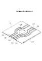
図2を参照すると、本発明第1実施形態に係るヘッドアセンブリ35の斜視図が示されている。例えば、ステンレス鋼から形成されたサスペンション34の先端部には図3に詳細に示されたMRヘッド32aを有するヘッドスライダ32が搭載されており、その基端部にはアクチュエータアーム30に取り付けるための穴65が設けられている。
【0024】
図3に示されるようにMRヘッド32aは、導電性基板66と、該導電性基板66上に積層された例えばアルミナ(Al2O3)からなる非磁性絶縁層68を有している。
【0025】
非磁性絶縁層68内には、例えばニッケル−鉄(Ni−Fe)から形成された第1及び第2磁気シールド70,72が埋め込まれている。第1及び第2磁気シールド70,72はヘッド32aの先端面(媒体対向面)75に再生分解能を向上させるためのギャップ74を画成している。
【0026】
非磁性絶縁層68内にはヘッド32aの先端面75から離間して例えばニッケル−鉄(Ni−Fe)から形成された磁気抵抗効果素子(MR素子)76が埋め込まれている。
【0027】
非磁性絶縁層68内には、更に、一端がヘッド32aの先端面75に露出し、他端が磁気抵抗効果素子76の一端に磁気的に結合した例えばニッケル−鉄(Ni−Fe)からなる前部フラックスガイド78が埋め込まれている。前部フラックスガイド78は記録媒体(磁気ディスク)20からの磁束を磁気抵抗効果素子76に案内する。
【0028】
符号80は後部フラックスガイドを示しており、前部フラックスガイド78と同様に例えばニッケル−鉄(Ni−Fe)から形成されており、その一端が磁気抵抗効果素子76に磁気的に結合している。
【0029】
特に図示しないが、磁気抵抗効果素子76の一対の端子にはセンス電流源が接続されており、磁気抵抗効果素子76にはセンス電流源から一定のセンス電流が供給される。
【0030】
符号84は一端がMRヘッド32aの先端面75に露出し、他端が第2磁気シールド72に結合した磁極であり、磁極84と第2磁気シールド72の結合部を概略中心として導体コイル82が巻回されている。
【0031】
コイル82に記録すべき情報で変調された電流を流すことにより、電流値に応じた磁界が誘導されて磁気ディスク20の記録トラックに情報を磁気的に記録することができる。
【0032】
磁気ディスク20に記録された情報の読み出しには磁気抵抗効果素子76を利用する。即ち、磁気ディスク20の記録トラックからの信号磁束はヘッド32a内に受け入れられ、前部フラックスガイド78に案内されて磁気抵抗効果素子76に流入し、磁気抵抗効果素子76を磁化させる。磁気抵抗効果素子76を通過した磁束は、後部フラックスガイド80を介して第1及び第2磁気シールド70,72に吸収される。
【0033】
磁気抵抗効果素子76は信号磁束の大きさの変化に応じて、その抵抗値が変化する。磁気抵抗効果素子76にはセンス電流源から一定のセンス電流が供給されているので、抵抗値の変化に応じて一対の端子間の電圧が変化し、磁気ディスク20に記録された情報を電圧信号として再生することができる。
【0034】
再び図2を参照すると、サスペンション34上には一対のリードライン50,52からなるMR配線パターン48と、同じく一対のリードライン56,58からなるコイル配線パターン54が印刷により形成されている。各リードライン50,52,56,58は例えば銅から形成されている。
【0035】
リードライン50,52の一端はMR素子76の端子にそれぞれ接続されている。一方、リードライン56,58の一端はコイル82にそれぞれ接続されている。
【0036】
図2において、サスペンション34の両側部にはサスペンションの剛性を確保するための一対のリブ(一方のみ図示)62がサスペンション34と一体的に形成されており、サスペンション34の基端部にはスペーサー64が接着等により固定されている。
【0037】
図4の要部拡大図に最もよく示されるように、リードライン50,52はMR短絡パターン60により接続されている。MR短絡パターン60はヘッドアセンブリ35をアクチュエータアーム30に取り付けた後に、容易に断線可能な材料から形成されている。
【0038】
例えば、MR短絡パターン60は低融点ハンダから形成されている。この場合、組み立て時のハンダ工程でMR短絡パターン60も同時に加熱され、圧縮エアで吹き飛ばすか、或いはバキュームで吸引する等の方法で容易にハンダを除去することができる。これにより、組み立て工程において、一対のリードライン50,52間を容易に電気的に開放状態とすることができる。
【0039】
代替案として、MR短絡パターン60を低融点合金から形成する。この場合、ヘッドアセンブリ35をアクチュエータアーム30に取り付け後、レーザビームをMR短絡パターン60に照射して断線させる。レーザビームは小さなスポットに絞ることができるので、サスペンション34が小型化されても、確実にMR短絡パターン60を断線でき、自動化も容易である。
【0040】
本実施形態によれば、ヘッドアセンブリ35単体で取り扱うときには、MR素子76に接続されたリードライン50,52間がMR短絡パターン60により短絡されているので、静電気等が原因で発生した電流はMR短絡パターン60を流れ、この電流がMR素子76を流れることが防止される。これにより、MR素子76が静電気が原因で発生した電流により焼損されることが防止される。
【0041】
図5を参照すると、本発明第2実施形態に係るヘッドアセンブリの要部拡大図が示されている。本実施形態では、サスペンション34上に一対のリードライン50,52に加えて、第1及び第2磁気シールド70,72を接地するための接地ライン86が形成されている。
【0042】
リードライン50,52間及びリードライン50,52と接地ライン86の間はMR−シールド間短絡パターン88,90により互いに接続されている。第1実施形態と同様に、短絡パターン88,90は容易に断線可能な材料から構成されている。
【0043】
本実施形態によると、リードライン50,52間及びリードライン50,52とシールド接地ライン86の間が短絡されているので、静電気等が原因で発生した電流がこれらの短絡パターン88,90を流れる。
【0044】
その結果、静電気等が原因で発生した電流がMR素子76を流れることが防止されると共に、MR素子76と磁気シールド70,72間で放電することが防止され、MR素子76が焼損することが防止される。
【0045】
図5に示した実施形態においては、2つの短絡パターン88,90により一対のリードライン50,52とシールド接地ライン86の間が短絡されているが、1つの連続した短絡パターンによりこれらの間を短絡するように構成することももちろん可能である。
【0046】
次に図6及び図7を参照して、本発明第3実施形態のヘッドアセンブリ35について説明する。本実施形態においては、図7に示すように短絡パターン60aの背面には穴94が形成されている。
【0047】
一方、アクチュエータアーム30の先端部には穴94中に挿入される突起92と、ヘッドアセンブリ35をアクチュエータアーム30に取り付けるためのピン93が挿入される穴31が形成されている。
【0048】
ピン93をサスペンション34の穴65及びアクチュエータアーム30の穴31中に圧入して、ヘッドアセンブリ35をアクチュエータアーム30に固定する。このとき、突起92がサスペンション34に形成された穴94中に挿入されるため、短絡パターン60aが突起92により破断される。
【0049】
これにより、ヘッドアセンブリ35を磁気ディスク装置のアクチュエータアーム30に取り付けると同時に、短絡パターン60aを容易に断線することができ、組み立て工程を簡単にすることができる。
【0050】
図8を参照すると、本発明第4実施形態に係るヘッドアセンブリの要部拡大図が示されている。本実施形態においては、リードライン50,52間は短絡スイッチ96により選択的に短絡・開放される。
【0052】
通常状態では実線で示すように、短絡スイッチ96はリードライン50,52間を短絡しているが、サスペンション34をアクチュエータアーム30に取り付けた状態では、図6及び図7に示した第3実施形態のように、穴94中に挿入された突起92により短絡スイッチ96が想像線で示すように押し上げられ、リードライン50,52間を電気的に開放する。
【0053】
図9は本発明第5実施形態に係るヘッドアセンブリの要部拡大図を示している。本実施形態においては、2個の短絡スイッチ98,100でリードライン50,52間及びリードライン50,52とシールド接地ライン86の間が選択的に短絡・開放される。
【0054】
本実施形態においては、第3実施形態と同様に、各短絡スイッチ98,100の背面にそれぞれ穴を設け、アクチュエータアーム30の先端部にこれらの穴中に挿入される2個の突起を設ける。
【0055】
これにより、サスペンション34をアクチュエータアーム30に取り付けた状態において、穴中に挿入された突起により短絡スイッチ98,100を押し上げ、リードライン50,52とシールド接地ライン86の間が開放される。
【0056】
図10は本発明第6実施形態の説明図であり、図11はその要部拡大図である。検査用アーム102の先端部には突起104と、ピン93が挿入される穴103が形成されている。一方、短絡スイッチ96の背面には突起104が挿入される穴94が形成されている。
【0057】
本実施形態においては、ピン93によりヘッドアセンブリ35を検査用アーム102に取り付けると、突起104が穴94中に挿入されて、短絡スイッチ96を押し上げリードライン50,52の間が電気的に開放される。
【0058】
これにより、ヘッドアセンブリ35を磁気ディスク装置の検査用アーム102に取り付けると同時に短絡スイッチ96を容易に開放することができ、又検査用アーム102からヘッドアセンブリ35を外すと同時に短絡スイッチ96でリードライン50,52間を再び短絡することができる。
【0059】
よって、MRヘッドの検査から最終組み立てまでヘッドアセンブリ35の取り付け及び取り外しが繰り返しある場合にも、MR素子76を焼損から保護することができる。
【0060】
上述した各実施形態は、本発明をヘッドスライダがMR素子を有する実施形態について説明したが、本発明はこれに限定されるものではなく、ヘッドスライダが一般的な電磁トランスデューサを有する場合にも適用可能であり、静電気が電磁トランスデューサに及ぼす悪影響を抑制することができる。
【0061】
【発明の効果】
本発明のヘッドアセンブリは以上詳述したように構成したので、ヘッドアセンブリ単体で取り扱うときにはMR素子の端子間及び/又はMR素子と磁気シールド間が電気的に短絡状態となっているため、MR素子の端子間に静電気による過大電流が加わってもこの電流は短絡パターン又は短絡スイッチを流れる。これにより、静電気の帯電に起因する過大電流がMR素子を流れることが防止される。
【0062】
更に、MR素子と磁気シールド間は短絡により同電位に近い状態となっているため、MR素子と磁気シールド間で帯電した静電気が放電を起こすのが防止される。その結果、静電気に起因するMR素子の焼損を防止することができる。
【図面の簡単な説明】
【図1】本発明のヘッドアセンブリを具備した磁気ディスク装置の斜視図である。
【図2】本発明第1実施形態に係るヘッドアセンブリ斜視図である。
【図3】MRヘッド部分断面図である。
【図4】本発明第1実施形態の要部拡大図である。
【図5】本発明第2実施形態の要部拡大図である。
【図6】本発明第3実施形態に係るヘッドアセンブリ斜視図である。
【図7】第3実施形態の要部拡大図である。
【図8】第4実施形態の要部拡大図である。
【図9】第5実施形態の要部拡大図である。
【図10】本発明第6実施形態に係るヘッドアセンブリ斜視図である。
【図11】第6実施形態の要部拡大図である。
【符号の説明】
32 ヘッドスライダ
32a MRヘッド
34 サスペンション
35 ヘッドアセンブリ
48 MR配線パターン
50,52,56,58 リードライン
54 コイル配線パターン
60,60a,88,90 MR短絡パターン
96,98,100 MR短絡スイッチ[0001]
BACKGROUND OF THE INVENTION
The present invention relates to a head assembly and a magnetic disk apparatus having the head assembly.
[0002]
In recent years, with the miniaturization and increase in density of magnetic disk devices, the flying height of the head slider has decreased, and it is desired to realize extremely low flying or contact recording / reproduction in which the slider contacts the recording medium.
[0003]
Further, in the conventional magnetic induction head, when the peripheral speed (relative speed between the head and the medium) decreases due to the reduction in the diameter of the magnetic disk, the reproduction output deteriorates. Therefore, it is desired to develop a magnetoresistive head (hereinafter abbreviated as an MR head) that can provide a large output even at a low peripheral speed, with the reproduction output not depending on the peripheral speed.
[0004]
[Prior art]
The MR head supplies a constant sense current to the magnetoresistive effect element, converts the change in the magnitude of the signal magnetic field leaking from the recording track of the recording medium into a resistance change, and changes the voltage value of the information recorded on the medium. Play as.
[0005]
An MR head is generally formed by integrally forming a magnetoresistive effect element (MR element) formed by a thin film process or the like on a head slider. The head slider further has a coil for writing data, and is mounted on the tip of a suspension made of stainless steel by bonding or the like.
[0006]
The lead wire for connecting the MR element and the coil to the recording / reproducing circuit of the magnetic disk device is composed of a copper pattern printed on the suspension. By attaching the suspension to the tip of the actuator arm, the MR element and the coil are connected to the recording / reproducing circuit via a flexible printed wiring board (FPC) or the like.
[0007]
[Problems to be solved by the invention]
In a conventional suspension for supporting an MR head slider, a pair of lead wires connecting the terminals of the MR element or a ground line connected to the magnetic shield of the MR element is electrically opened. ing.
[0008]
Therefore, when an electrostatically charged operator handles a suspension equipped with an MR head slider or carries it in a case that is easily charged, such as a synthetic resin, an excessive current due to charging flows through the MR element and the MR element There was a problem that the MR element was burnt out or the static electricity charged between the MR element and the magnetic shield was discharged to burn out the MR element.
[0009]
Accordingly, an object of the present invention is to provide a head assembly that can prevent the MR element from being burned out due to static electricity.
[0010]
[Means for Solving the Problems]
According to the present invention, there is provided amagnetic disk device comprising: a housing; a magnetic disk rotatably mounted in the housing; a head slider having a magnetoresistive effect element for reading data from the magnetic disk; and the head slider. An actuator that moves across the track of the magnetic disk; the actuator being rotatably mounted on the housing; and a distal end that supports the head slider and a proximal end that is the distal end of the actuator arm. A suspension fixed to a portion; the actuator arm has a protrusion at the tip; the suspension has a pair of lead lines each having one end connected to the magnetoresistive element; and the protrusion Is inserted into the hole, and into the hole Magnetic disk apparatus characterized by being broken by serial protrusion has a short-circuit pattern electrically opening the pair of lead lines are provided.
[0011]
When a ground line connected to the magnetic shield of the magnetoresistive element is formed on the suspension, the short-circuit pattern connects a pair of lead lines and between the lead line and the ground line.
[0012]
According to another aspect of the present invention, there is provided amagnetic disk device including a housing; a magnetic disk rotatably mounted in the housing; a head slider having a magnetoresistive effect element for reading data from the magnetic disk; An actuator that moves the head slider across a track of the magnetic disk; the actuator is an actuator arm that is rotatably attached to the housing; and a base end portion that supports the head slider at a distal end portion; A suspension fixed to a distal end portion of the actuator arm; the actuator arm has a protrusion at the distal end portion, and the suspension has a pair of lead lines each having one end connected to the magnetoresistive effect element. And a hole into which the protrusion is inserted, and in the hole Magnetic disk apparatus characterized by being pushed up by the entrance to said projection has a short-circuit switch to electrically open the pair of lead lines are provided.
[0015]
DETAILED DESCRIPTION OF THE INVENTION
Referring to FIG. 1, there is shown a perspective view of a magnetic disk apparatus on which the head assembly of the present invention is mounted.
[0016]
On the
[0017]
[0018]
The
[0019]
A
[0020]
A
[0021]
[0022]
An
[0023]
Referring to FIG. 2, a perspective view of the
[0024]
As shown in FIG. 3, the MR head 32 a includes a
[0025]
Embedded in the nonmagnetic insulating
[0026]
A magnetoresistive effect element (MR element) 76 made of, for example, nickel-iron (Ni-Fe) is embedded in the nonmagnetic insulating
[0027]
In the nonmagnetic insulating
[0028]
[0029]
Although not particularly shown, a sense current source is connected to a pair of terminals of the
[0030]
[0031]
By passing a current modulated with information to be recorded in the
[0032]
A
[0033]
The resistance value of the
[0034]
Referring to FIG. 2 again, an
[0035]
One ends of the lead lines 50 and 52 are connected to terminals of the
[0036]
In FIG. 2, a pair of ribs 62 (only one is shown) 62 is formed integrally with the
[0037]
As best shown in the enlarged view of the main part of FIG. 4, the lead lines 50 and 52 are connected by the MR short-
[0038]
For example, the MR short-
[0039]
As an alternative, the MR short-
[0040]
According to the present embodiment, when the
[0041]
Referring to FIG. 5, an enlarged view of a main part of a head assembly according to a second embodiment of the present invention is shown. In this embodiment, in addition to the pair of
[0042]
The lead lines 50 and 52 and the lead lines 50 and 52 and the
[0043]
According to the present embodiment, since the lead lines 50 and 52 and between the
[0044]
As a result, current generated due to static electricity or the like is prevented from flowing through the
[0045]
In the embodiment shown in FIG. 5, the pair of
[0046]
Next, a
[0047]
On the other hand, a
[0048]
The
[0049]
As a result, the
[0050]
Referring to FIG. 8, an enlarged view of the main part of the head assembly according to the fourth embodiment of the present invention is shown. In the present embodiment, the lead lines 50 and 52 are selectively short-circuited / opened by the short-
[0052]
In the normal state, as indicated by the solid line, the short-
[0053]
FIG. 9 shows an enlarged view of the main part of the head assembly according to the fifth embodiment of the present invention. In the present embodiment, the two short-
[0054]
In the present embodiment, as in the third embodiment, holes are provided on the back surfaces of the respective short-
[0055]
Thereby, in a state where the
[0056]
FIG. 10 is an explanatory view of a sixth embodiment of the present invention, and FIG. 11 is an enlarged view of a main part thereof. A
[0057]
In this embodiment, when the
[0058]
As a result, the
[0059]
Therefore, even when the attachment and removal of the
[0060]
In each of the embodiments described above, the present invention has been described with respect to an embodiment in which the head slider has an MR element. However, the present invention is not limited to this, and the present invention is also applicable to a case in which the head slider has a general electromagnetic transducer. It is possible to suppress adverse effects of static electricity on the electromagnetic transducer.
[0061]
【The invention's effect】
Since the head assembly of the present invention is configured as described in detail above, the MR element is electrically short-circuited between the terminals of the MR element and / or between the MR element and the magnetic shield when handled as a single head assembly. Even if an excessive current due to static electricity is applied between these terminals, this current flows through the short-circuit pattern or the short-circuit switch. This prevents an excessive current due to static electricity from flowing through the MR element.
[0062]
Furthermore, since the MR element and the magnetic shield are close to the same potential due to a short circuit, the static electricity charged between the MR element and the magnetic shield is prevented from being discharged. As a result, burnout of the MR element due to static electricity can be prevented.
[Brief description of the drawings]
FIG. 1 is a perspective view of a magnetic disk drive equipped with a head assembly of the present invention.
FIG. 2 is a perspective view of a head assembly according to the first embodiment of the present invention.
FIG. 3 is a partial sectional view of an MR head.
FIG. 4 is an enlarged view of a main part of the first embodiment of the present invention.
FIG. 5 is an enlarged view of a main part of a second embodiment of the present invention.
FIG. 6 is a perspective view of a head assembly according to a third embodiment of the present invention.
FIG. 7 is an enlarged view of a main part of a third embodiment.
FIG. 8 is an enlarged view of a main part of a fourth embodiment.
FIG. 9 is an enlarged view of a main part of a fifth embodiment.
FIG. 10 is a perspective view of a head assembly according to a sixth embodiment of the present invention.
FIG. 11 is an enlarged view of a main part of a sixth embodiment.
[Explanation of symbols]
32 Head slider
Claims (4)
Translated fromJapaneseハウジングと;
該ハウジング内に回転可能に取り付けられた磁気ディスクと;
前記磁気ディスクからデータを読み出す磁気抵抗効果素子を有するヘッドスライダと;
前記ヘッドスライダを磁気ディスクのトラックを横切って移動させるアクチュエータとを具備し;
前記アクチュエータは、前記ハウジングに回転可能に取り付けられたアクチュエータアームと;
先端部で前記ヘッドスライダを支持し基端部が前記アクチュエータアームの先端部に固定されたサスペンションとを具備し;
前記アクチュエータアームは前記先端部に突起を有しており、前記サスペンションはそれぞれの一端が前記磁気抵抗効果素子に接続された一対のリードラインと、前記突起が挿入される穴と、該穴中に挿入された前記突起により破断されて前記一対のリードラインを電気的に開放する短絡パターンを有していることを特徴とする磁気ディスク装置。A magnetic disk drive,
A housing;
A magnetic disk rotatably mounted in the housing;
A head slider having a magnetoresistive effect element for reading data from the magnetic disk;
An actuator for moving the head slider across the track of the magnetic disk;
The actuator includes an actuator arm rotatably attached to the housing;
A suspension supporting the head slider at a distal end and having a proximal end fixed to the distal end of the actuator arm;
The actuator arm has a protrusion at the tip, and the suspension has a pair of lead lines each having one end connected to the magnetoresistive element, a hole into which the protrusion is inserted, and a hole in the hole. A magnetic disk drive having a short-circuit pattern that is broken by the inserted protrusion to electrically open the pair of lead lines.
ハウジングと;
該ハウジング内に回転可能に取り付けられた磁気ディスクと;
前記磁気ディスクからデータを読み出す磁気抵抗効果素子を有するヘッドスライダと;
前記ヘッドスライダを磁気ディスクのトラックを横切って移動させるアクチュエータとを具備し;
前記アクチュエータは、前記ハウジングに回転可能に取り付けられたアクチュエータアームと;
先端部で前記ヘッドスライダを支持し基端部が前記アクチュエータアームの先端部に固定されたサスペンションとを具備し;
前記アクチュエータアームは前記先端部に突起を有しており、前記サスペンションはそれぞれの一端が前記磁気抵抗効果素子に接続された一対のリードラインと、前記突起が挿入される穴と、該穴中に挿入された前記突起により押し上げられて前記一対のリードラインを電気的に開放する短絡スイッチを有していることを特徴とする磁気ディスク装置。A magnetic disk drive,
A housing;
A magnetic disk rotatably mounted in the housing;
A head slider having a magnetoresistive effect element for reading data from the magnetic disk;
An actuator for moving the head slider across the track of the magnetic disk;
The actuator includes an actuator arm rotatably attached to the housing;
A suspension supporting the head slider at a distal end and having a proximal end fixed to the distal end of the actuator arm;
The actuator arm has a protrusion at the tip, and the suspension has a pair of lead lines each having one end connected to the magnetoresistive element, a hole into which the protrusion is inserted, and a hole in the hole. A magnetic disk drive comprising a short-circuit switch that is pushed up by the inserted protrusion to electrically open the pair of lead lines.
Priority Applications (2)
| Application Number | Priority Date | Filing Date | Title |
|---|---|---|---|
| JP03955397AJP3874875B2 (en) | 1997-02-24 | 1997-02-24 | Magnetic disk unit |
| US08/905,327US5991121A (en) | 1997-02-24 | 1997-08-01 | Head assembly having short circuit pattern short-circuiting a pair of lead lines |
Applications Claiming Priority (1)
| Application Number | Priority Date | Filing Date | Title |
|---|---|---|---|
| JP03955397AJP3874875B2 (en) | 1997-02-24 | 1997-02-24 | Magnetic disk unit |
Publications (2)
| Publication Number | Publication Date |
|---|---|
| JPH10241132A JPH10241132A (en) | 1998-09-11 |
| JP3874875B2true JP3874875B2 (en) | 2007-01-31 |
Family
ID=12556267
Family Applications (1)
| Application Number | Title | Priority Date | Filing Date |
|---|---|---|---|
| JP03955397AExpired - Fee RelatedJP3874875B2 (en) | 1997-02-24 | 1997-02-24 | Magnetic disk unit |
Country Status (2)
| Country | Link |
|---|---|
| US (1) | US5991121A (en) |
| JP (1) | JP3874875B2 (en) |
Families Citing this family (13)
| Publication number | Priority date | Publication date | Assignee | Title |
|---|---|---|---|---|
| JPH11175931A (en)* | 1997-12-16 | 1999-07-02 | Nec Corp | Magneto-resistive effect combined head and magnetic disk device |
| US5924187A (en)* | 1998-01-06 | 1999-07-20 | Hutchinson Technology Incorporated | Integrated lead head suspension assembly having an etched laminated load beam and flexure with deposited conductors |
| JP3576368B2 (en)* | 1998-02-19 | 2004-10-13 | 富士通株式会社 | Actuator assembly and method of assembling the same |
| JP3923174B2 (en)* | 1998-04-28 | 2007-05-30 | 富士通株式会社 | Head assembly and suspension |
| US6326553B1 (en)* | 1998-10-16 | 2001-12-04 | Samsung Electronics, Co., Ltd | Scheme to avoid electrostatic discharge damage to MR/GMR head gimbal/stack assembly in hard disk applications |
| JP3501758B2 (en)* | 1998-11-13 | 2004-03-02 | Tdk株式会社 | Recording / reproducing head support mechanism and recording / reproducing apparatus |
| US6275361B1 (en)* | 1999-05-13 | 2001-08-14 | Maxtor Corporation | Protecting a magnetoresistive head against electrostatic discharge |
| US6518521B1 (en)* | 1999-09-02 | 2003-02-11 | Hutchinson Technology Incorporated | Switchable shunts for integrated lead suspensions |
| US6700748B1 (en) | 2000-04-28 | 2004-03-02 | International Business Machines Corporation | Methods for creating ground paths for ILS |
| US6872896B1 (en) | 2001-09-12 | 2005-03-29 | Hutchinson Technology Incorporated | Elongated bridge shunt |
| CN100351902C (en)* | 2001-12-29 | 2007-11-28 | 易拓控股公司 | Hard disk drive read and write magnetic sensor to eliminate overcurrent impact device |
| US7355818B2 (en)* | 2004-05-12 | 2008-04-08 | Seagate Technology Llc | Disc drive integral actuator pins |
| US7282376B2 (en)* | 2004-10-28 | 2007-10-16 | Hitachi Global Storage Technologies Netherlands Bv | System, method, and apparatus for electrically testing lead-to-lead shorting during magnetoresistive sensor fabrication |
Family Cites Families (15)
| Publication number | Priority date | Publication date | Assignee | Title |
|---|---|---|---|---|
| US4317149A (en)* | 1980-06-02 | 1982-02-23 | International Business Machines Corporation | Magnetic head having static discharge means |
| JP2607184B2 (en)* | 1991-06-13 | 1997-05-07 | 富士通株式会社 | Thin film magnetic head and method for preventing dielectric breakdown thereof |
| JP2937720B2 (en)* | 1993-11-16 | 1999-08-23 | アルプス電気株式会社 | Composite magnetic head and FPC |
| US5465186A (en)* | 1994-01-26 | 1995-11-07 | International Business Machines Corporation | Shorted magnetoresistive head leads for electrical overstress and electrostatic discharge protection during manufacture of a magnetic storage system |
| US5467881A (en)* | 1994-06-28 | 1995-11-21 | International Business Machines Corporation | Method of manufacturing an MR read head which eliminates lead-to-shield shorts at the ABS of the MR read head |
| DE4428226C1 (en)* | 1994-08-10 | 1995-10-12 | Thermik Geraetebau Gmbh | Temp. monitoring switch e.g. for electric motor or transformer |
| US5539598A (en)* | 1994-12-08 | 1996-07-23 | International Business Machines Corporation | Electrostatic protection for a shielded MR sensor |
| JPH08167123A (en)* | 1994-12-13 | 1996-06-25 | Hitachi Ltd | Magnetic head manufacturing method, substrate having magnetic head element group, and method of manufacturing substrate having magnetic head element group |
| US5491605A (en)* | 1994-12-23 | 1996-02-13 | International Business Machines Corporation | Shorted magnetoresistive head elements for electrical overstress and electrostatic discharge protection |
| JPH08315321A (en)* | 1995-05-16 | 1996-11-29 | Yamaha Corp | Connector structure of lead wire end of mr head |
| US5638237A (en)* | 1995-08-25 | 1997-06-10 | International Business Machines Corporation | Fusible-link removable shorting of magnetoresistive heads for electrostatic discharge protection |
| US5754355A (en)* | 1995-09-21 | 1998-05-19 | International Business Machines Corporation | Disk drive apparatus and read error recovery method in a disk drive apparatus |
| US5644454A (en)* | 1996-03-11 | 1997-07-01 | International Business Machines Corporation | Electrostatic discharge protection system for MR heads |
| US5759428A (en)* | 1996-03-15 | 1998-06-02 | International Business Machines Corporation | Method of laser cutting a metal line on an MR head |
| US5699212A (en)* | 1996-05-01 | 1997-12-16 | International Business Machines Corporation | Method of electrostatic discharge protection of magnetic heads in a magnetic storage system |
- 1997
- 1997-02-24JPJP03955397Apatent/JP3874875B2/ennot_activeExpired - Fee Related
- 1997-08-01USUS08/905,327patent/US5991121A/ennot_activeExpired - Fee Related
Also Published As
| Publication number | Publication date |
|---|---|
| JPH10241132A (en) | 1998-09-11 |
| US5991121A (en) | 1999-11-23 |
Similar Documents
| Publication | Publication Date | Title |
|---|---|---|
| JP3923174B2 (en) | Head assembly and suspension | |
| JP3576368B2 (en) | Actuator assembly and method of assembling the same | |
| US6583968B1 (en) | Spindle motor hub having equivalent MR read element bias voltage to mitigate potential between disk and MR read element | |
| US7006330B1 (en) | Head stack assembly including a ground conductive pad for grounding a slider to a gimbal | |
| JP3874875B2 (en) | Magnetic disk unit | |
| US6034851A (en) | Shorting bar and test clip for protecting magnetic heads from damage caused by electrostatic discharge during manufacture | |
| US6160688A (en) | Magneto-resistive composite head and a magnetic disk device, having grounded magnetic shielding layers | |
| EP0470349B1 (en) | A disk drive in which magnetic head-to-disk capacitive coupling is eliminated | |
| US6377411B1 (en) | Head IC, head amplifier circuit, head suspension assembly, and magnetic disk drive for avoiding electrostatic breakdown of magnetic head | |
| US6256175B1 (en) | Magnetic shielding for electromagnetic microactuator | |
| US6836391B2 (en) | Magnetic head slider and magnetic head assembly with short-circuiting switching element | |
| US6507467B1 (en) | Comb shunt for ESD protection | |
| JPH1145423A (en) | Magnetic head slider and magnetic head assembly | |
| JP4054801B2 (en) | Interconnect circuit that dissipates static charge on head slider, electrostatic voltage dissipation method | |
| JP2937720B2 (en) | Composite magnetic head and FPC | |
| US7271968B2 (en) | Head protection circuit of hard disk drive | |
| JP4081937B2 (en) | Manufacturing method of rotary magnetic head device | |
| KR0155046B1 (en) | Devices for Improving Conductivity from Thin Film Heads in Hard Disk Drives | |
| JP3226883B2 (en) | Method of manufacturing MR element, magnetic head, FPC, and magnetic disk drive | |
| KR100505582B1 (en) | Head actuator of hard disk drive | |
| JPS5968804A (en) | Magnetic recorder and reproducer | |
| JPH0963019A (en) | Magnetoresistive head and magnetic disk device using the head | |
| JP2000331301A (en) | Magnetic head device | |
| JP2004127338A (en) | Magnetic disk drive | |
| JPH05307726A (en) | Magnetic head device for flexible disk |
Legal Events
| Date | Code | Title | Description |
|---|---|---|---|
| A977 | Report on retrieval | Free format text:JAPANESE INTERMEDIATE CODE: A971007 Effective date:20060118 | |
| A131 | Notification of reasons for refusal | Free format text:JAPANESE INTERMEDIATE CODE: A131 Effective date:20060131 | |
| A521 | Written amendment | Free format text:JAPANESE INTERMEDIATE CODE: A523 Effective date:20060331 | |
| TRDD | Decision of grant or rejection written | ||
| A01 | Written decision to grant a patent or to grant a registration (utility model) | Free format text:JAPANESE INTERMEDIATE CODE: A01 Effective date:20061024 | |
| A61 | First payment of annual fees (during grant procedure) | Free format text:JAPANESE INTERMEDIATE CODE: A61 Effective date:20061025 | |
| R150 | Certificate of patent or registration of utility model | Free format text:JAPANESE INTERMEDIATE CODE: R150 | |
| FPAY | Renewal fee payment (event date is renewal date of database) | Free format text:PAYMENT UNTIL: 20101102 Year of fee payment:4 | |
| FPAY | Renewal fee payment (event date is renewal date of database) | Free format text:PAYMENT UNTIL: 20101102 Year of fee payment:4 | |
| S111 | Request for change of ownership or part of ownership | Free format text:JAPANESE INTERMEDIATE CODE: R313111 | |
| FPAY | Renewal fee payment (event date is renewal date of database) | Free format text:PAYMENT UNTIL: 20101102 Year of fee payment:4 | |
| R350 | Written notification of registration of transfer | Free format text:JAPANESE INTERMEDIATE CODE: R350 | |
| FPAY | Renewal fee payment (event date is renewal date of database) | Free format text:PAYMENT UNTIL: 20101102 Year of fee payment:4 | |
| FPAY | Renewal fee payment (event date is renewal date of database) | Free format text:PAYMENT UNTIL: 20111102 Year of fee payment:5 | |
| LAPS | Cancellation because of no payment of annual fees |