JP3874826B2 - Method for simulating an endoscope and virtual examination system for obtaining a view of the lumen of a subject - Google Patents
Method for simulating an endoscope and virtual examination system for obtaining a view of the lumen of a subjectDownload PDFInfo
- Publication number
- JP3874826B2 JP3874826B2JP30405995AJP30405995AJP3874826B2JP 3874826 B2JP3874826 B2JP 3874826B2JP 30405995 AJP30405995 AJP 30405995AJP 30405995 AJP30405995 AJP 30405995AJP 3874826 B2JP3874826 B2JP 3874826B2
- Authority
- JP
- Japan
- Prior art keywords
- observation position
- path
- image
- voxel
- subject
- Prior art date
- Legal status (The legal status is an assumption and is not a legal conclusion. Google has not performed a legal analysis and makes no representation as to the accuracy of the status listed.)
- Expired - Fee Related
Links
- 238000000034methodMethods0.000titleclaimsdescription33
- 238000004364calculation methodMethods0.000claimsdescription11
- 238000009499grossingMethods0.000claimsdescription9
- 238000002372labellingMethods0.000claims1
- 238000003384imaging methodMethods0.000abstractdescription18
- 238000007689inspectionMethods0.000abstractdescription4
- 230000004807localizationEffects0.000abstract1
- 238000007794visualization techniqueMethods0.000abstract1
- 210000001519tissueAnatomy0.000description13
- 239000007787solidSubstances0.000description12
- 238000002591computed tomographyMethods0.000description9
- 210000000056organAnatomy0.000description6
- 210000001072colonAnatomy0.000description4
- 238000002595magnetic resonance imagingMethods0.000description4
- 238000013507mappingMethods0.000description4
- 238000010586diagramMethods0.000description3
- 230000000750progressive effectEffects0.000description3
- 239000013598vectorSubstances0.000description3
- 238000012800visualizationMethods0.000description3
- 238000013459approachMethods0.000description2
- 210000004204blood vesselAnatomy0.000description2
- 238000004422calculation algorithmMethods0.000description2
- 238000007796conventional methodMethods0.000description2
- 238000009432framingMethods0.000description2
- 230000002452interceptive effectEffects0.000description2
- 238000012986modificationMethods0.000description2
- 230000004048modificationEffects0.000description2
- 238000002604ultrasonographyMethods0.000description2
- CVOFKRWYWCSDMA-UHFFFAOYSA-N2-chloro-n-(2,6-diethylphenyl)-n-(methoxymethyl)acetamide;2,6-dinitro-n,n-dipropyl-4-(trifluoromethyl)anilineChemical compoundCCC1=CC=CC(CC)=C1N(COC)C(=O)CCl.CCCN(CCC)C1=C([N+]([O-])=O)C=C(C(F)(F)F)C=C1[N+]([O-])=OCVOFKRWYWCSDMA-UHFFFAOYSA-N0.000description1
- 206010002091AnaesthesiaDiseases0.000description1
- 206010039897SedationDiseases0.000description1
- 230000037005anaesthesiaEffects0.000description1
- 210000003484anatomyAnatomy0.000description1
- 210000000709aortaAnatomy0.000description1
- 210000001367arteryAnatomy0.000description1
- 210000000621bronchiAnatomy0.000description1
- 230000002490cerebral effectEffects0.000description1
- 238000000354decomposition reactionMethods0.000description1
- 238000013461designMethods0.000description1
- 230000001066destructive effectEffects0.000description1
- 238000001514detection methodMethods0.000description1
- 201000010099diseaseDiseases0.000description1
- 208000037265diseases, disorders, signs and symptomsDiseases0.000description1
- 230000009189divingEffects0.000description1
- 238000001839endoscopyMethods0.000description1
- 210000001035gastrointestinal tractAnatomy0.000description1
- 210000000936intestineAnatomy0.000description1
- 230000003340mental effectEffects0.000description1
- 238000012545processingMethods0.000description1
- 230000036280sedationEffects0.000description1
- 238000004088simulationMethods0.000description1
- 210000003625skullAnatomy0.000description1
- 238000002945steepest descent methodMethods0.000description1
- 239000013589supplementSubstances0.000description1
- 238000012360testing methodMethods0.000description1
Images


Classifications
- G—PHYSICS
- G09—EDUCATION; CRYPTOGRAPHY; DISPLAY; ADVERTISING; SEALS
- G09B—EDUCATIONAL OR DEMONSTRATION APPLIANCES; APPLIANCES FOR TEACHING, OR COMMUNICATING WITH, THE BLIND, DEAF OR MUTE; MODELS; PLANETARIA; GLOBES; MAPS; DIAGRAMS
- G09B23/00—Models for scientific, medical, or mathematical purposes, e.g. full-sized devices for demonstration purposes
- G09B23/28—Models for scientific, medical, or mathematical purposes, e.g. full-sized devices for demonstration purposes for medicine
- G09B23/285—Models for scientific, medical, or mathematical purposes, e.g. full-sized devices for demonstration purposes for medicine for injections, endoscopy, bronchoscopy, sigmoidscopy, insertion of contraceptive devices or enemas
Landscapes
- Engineering & Computer Science (AREA)
- Health & Medical Sciences (AREA)
- General Physics & Mathematics (AREA)
- Physics & Mathematics (AREA)
- Mathematical Physics (AREA)
- Pure & Applied Mathematics (AREA)
- Medical Informatics (AREA)
- Medicinal Chemistry (AREA)
- Chemical & Material Sciences (AREA)
- Algebra (AREA)
- Computational Mathematics (AREA)
- Radiology & Medical Imaging (AREA)
- Mathematical Analysis (AREA)
- Mathematical Optimization (AREA)
- Pulmonology (AREA)
- General Health & Medical Sciences (AREA)
- Business, Economics & Management (AREA)
- Educational Administration (AREA)
- Educational Technology (AREA)
- Theoretical Computer Science (AREA)
- Processing Or Creating Images (AREA)
- Image Processing (AREA)
- Magnetic Resonance Imaging Apparatus (AREA)
- Apparatus For Radiation Diagnosis (AREA)
- Instruments For Viewing The Inside Of Hollow Bodies (AREA)
- Endoscopes (AREA)
- Image Generation (AREA)
- Image Analysis (AREA)
Abstract
Description
Translated fromJapanese【0001】
【関連出願】
本出願は、1992年1月2日に出願されたジョナサン・エー・ザーゲ及びウィリアム・ジェー・シュレーダ(Jonathan A,Zarge and William J.Schroeder)による米国特許出願第07/815,772号、「多角形メッシュの複雑さを低減するための方法」(A Method for Reducing the Complexity of a Polygonal Mesh)、並びに1993年10月28日に出願されたウィリアム・イー・ローレンセン(William E.Lorensen)による米国特許出願第08/144,270号、「ブール組織を用いた幾何学的クリッピング」(Geometric Clipping Using Boolean Textures)(「組織写像」(Texture Mapping))に関連する。この2つの特許共に、本発明の譲り受け人に譲渡されている。
【0002】
【産業上の利用分野】
本発明は、固体内の導管の可視化に関し、更に詳しくは、イメージングデータから、導管内からのビュー(view)を非侵襲的に模擬することに関する。
【0003】
【従来の技術】
導管内の観察位置からの、固体被検体を通る導管のビューを得ることが必要になることがある。被検体が患者である場合には、結腸、腸、気管支、動脈等で閉塞又は組織のビューを得る必要がある。内視鏡は、人体の内部に存在している中空臓器及び腔の内部の実時間、高分解能のビューを提供するような装置である。内視鏡検査の多くは非侵襲的であるが、患者の不快感を低減するためには手順に尚、鎮静又は麻酔が必要になる。
【0004】
内視鏡に類似した内部観察装置を非医用環境で用いて、固体構造内の導管を観察することができる。これらのうちのある装置では、導管若しくは腔が外部への開口を有していないか、又は外部への連続的な開口があっても内部観察装置を受け入れるのに十分大きくないために、内部を見ることができない。
内部観察装置のもう1つの問題は、視野が導管の内側の小さな区域に限られるということである。被検体内の正確な位置を決定することにより、内部イメージング装置からの画像を被検体の大きな組織と相関させることは非常に難しい。
【0005】
被検体内の位置を決定するために、X線コンピュータ断層撮影(CT(Computed Tomography))及び磁気共鳴イメージング(MRI(Magnetic Resonance Imaging))を用いて被検体の内部解剖学的構造を表示してきた。これらの方法は、非破壊的/非侵襲的イメージング手法である。典型的にはこれらを用いて、内部イメージング装置によって得られる画像を補足することにより、観察している画像を被検体内の位置と相関させようとしてきた。
【0006】
医用環境では、放射線医が通常、二次元(2D(two−dimensional))の断面を見て、三次元構造の心的画像を作成し、導管内からの画像を被検体内のそれの三次元位置に相関させる。しかしながら、被検体が複雑な内部構造を有していると、例えば身体内の管状組織は、断面を繰り返し前後に横切る。
固体の内部導管の画像を非侵襲的に表示すると共に、そのビューが被検体内のどこで取得されているかを表すことのできる装置が現在必要とされている。
【0007】
【発明の目的】
本発明の1つの目的は、被検体内の腔の画像と共に、被検体全体に対する内部画像の観察位置を表す画像を非侵襲的に求める表示システムを提供することにある。
本発明のもう1つの目的は、被検体の外側への開口を有していない被検体の腔内の構造及び表面を操作者が見えるようにするシステムを提供することにある。
【0008】
【発明の概要】
本発明は、内部の「仮想内視鏡」ビュー及び内視鏡の瞬時位置を示す大きな全体ビューの両方の形式のビューを提供する。
新規であると考えられる本発明の特徴は、特許請求の範囲に明確に記述されている。しかしながら、本発明自体の構成及び動作方法、並びに本発明の上述以外の目的及び利点は、図面と共に以下の説明を参照することにより最も良く理解することができる。
【0009】
【実施例】
本発明により、被検体内部の導管の可視化、並びにこれらの導管内の表面及び構造の探査が可能となる。
図1に示すように、本発明による仮想腔検査システムは、次のようないくつかの下位(サブ)システムを含んでいる。
【0010】
1.被検体の内部構造のイメージング情報を非侵襲的に発生することが可能な画像取得ユニット21。これはX線コンピュータ断層撮影(CT(Computed Tomography))及び磁気共鳴イメージング(MRI(Magnetic Resonance Imaging))、又は超音波システムとすることができる。
【0011】
2.イメージング情報により記述された体積内の関心のある組織を識別する分解ユニット23。
3.選択された各組織の多角形モデルを作成する表面抽出器25。
4.多角形データの組を変換すると共に操作することが可能なモデル表現器29。
【0012】
5.イメージング情報を記憶するための機能的に分割されたメモリ。
6.選択的に、ユーザによって選択された臓器を通る「安全」な軌道を計算する経路探索下位(サブ)システム35。
[画像取得]
X線コンピュータ断層撮影(CT)、磁気共鳴イメージング(MRI)、又は超音波システムを取得ユニット21として用いることにより、被検体3の内部構造に関連する多次元イメージング情報を取得することができる。この情報は、事前に取得してメモリ10に記憶しておいてもよいし、又は必要に応じて対話的に取得してもよい。メモリ10は、メモリ10に記憶された他の情報を乱すことなく種々の形式の情報を独立に記憶すると共に検索することができるように、機能的に分割されている。
[分割]
メモリ10に記憶されたイメージング情報は、分割ユニット23に供給される。分割ユニット23は、イメージング情報を分析し、同じ型の組織を有している隣接位置を確定して、これらのすべての位置を臓器として識別する。これにより、情報は位置に応じて識別可能な固体構造に分割される。ここで、従来の分割方法を用いてもよい。本発明と両立し得る分割手法が、1988年6月14日に付与されたダブリュー・ローレンセン、エッチ・クライン(W.Lorensen,H.Cline)による米国特許第4,751,643号、「身体内の連結された構造を決定するための方法及び装置」(Method and Apparatus for Determining Connected Substructures Within a Body)に記述されている。使用可能な第2の方法が、1993年2月16日に付与されたエッチ・クライン、ダブリュー・ローレンセン(H.Cline,W.Lorensen)による米国特許第5,187,658号、「固体対象物の内部領域内に含まれている内部構造を分割するためのシステム及び方法」(System and Method for Segmenting Internal Structures Contained Within The Interior Region of a Solid Object)に記述されている。両方の特許共に、本発明の譲り受け人に譲渡され、ここに引用されている。
[表面抽出器]
画像情報のボクセルが、分割され、組織/臓器識別子でラベル付けされると、進行立方体(マーチング・キューブ)アルゴリズムのような従来の手法を用いている表面抽出器25によってイメージング・ユニット21からの体積データから表面モデルを作成することができる。進行立方体アルゴリズムについては、1987年12月1日に付与され、本発明の譲り受け人に譲渡されたハーベイ・イー・クライン及びウィリアム・イー・ローレンセン(Harvey E.Cline and William E.Lorensen)による米国特許第4,710,876号、「固体の内部領域内に含まれている表面構造の表示のためのシステム及び方法」(System and Method for the Display of Surface Structures Contained Within the Interior Region of a Solid Body)(「進行立方体法」Marching Cubes method)に記述されている。この特許は、ここに参照されるべきものである。
【0013】
進行立方体法では、線形補間を用いて、確認された組織の表面点を突き止めることにより、8つの隣接したボクセルによって画定されている「立方体」内の組織境界を突き止める。ボクセル・データの勾配から三角形の頂点ごとに、表面に垂直な単位ベクトルも得られる。内視鏡の用途の場合には、点及び直接体積表現よりも、三角形で画定された表面の方が好ましい。所望の対話表現速度に対して、体積データの再補間は計算の観点で費用がかかり過ぎるからである。
【0014】
表面のモデルを作成するために多数の三角形が必要とされることが多いので、間引き器(デシメータ)27によって表面の比較的平らな部分で三角形の数を少なくする。間引き器27は、上述の「関連出願」の欄で挙げたザルゲ、シュレーダ(Zarge,Schroeder)による「間引きの応用」のような多数の異なる公知の間引き方法を用いることができる。間引きされた表面は、細部のわずかな損失だけで表現速度を改善する。
【0015】
モデルを表示するもう1つの方法が、1988年1月12日に付与され、本発明の譲り受け人に譲渡されたハーベイ・イー・クライン、ジーグバルト・ルトケ及びウィリアム・イー・ローレンセン(Harvey E.Cline,Siegwalt Ludke and William E.Lorensen)による米国特許第4,719,585号、「固体の内部領域内に含まれている表面構造の表示のための立方体分割システム及び方法」(Dividing Cubes System and Method for the Displayof Surface Structures Contained Within the Interior Region of a Solid Body)(「立方体分割」(Dividing Cubes))に記述されている。この特許は、ここに参照されるべきものである。この方法では、ボリウム(体積)データで始まり、多角形よりむしろ、各点に関連する多数の点ベクトル及び法線ベクトルによって記述された表面が形成される。「立方体分割」法は、体積測定データ内に含まれている表面を表示するために用いられてきた。
【0016】
間引きは、点表示及び法線表示のような、規則正しい間隔の情報を必要とする表示に対しては用いることができない。
間引き器27からの間引きされた画像情報は、三次元(3D)表面モデルを記述しており、メモリ10に記憶されている。モデル表現器29は、選択された観察位置から見た三次元表面モデルの画像を形成する。表現器29は、従来のコンピュータ・グラフィック表現設計に従って構成することができる。
[仮想カメラ観察位置]
本発明は、3つの手法のどれかを用いることにより、三次元表面モデルの画像観察位置、又は一連の画像観察位置を選択することができる。これらの観察位置をまとめて観察位置経路と呼ぶことにする。
【0017】
第1の手法では、操作者がコンピュータ・マウスのようなグラフィック・インタフェース31で画像観察位置を制御する。グラフィック・インタフェース31によって、画像観察位置を動かすことができる。操作者5はグラフィック・インタフェース31で視野及び表現器29の他のイメージング・パラメータを制御することができる。この手動手法は、手術の計画及び手術のシミュレーションのような用途に最も適している。
【0018】
第2の手法は、キー・フレーミングと呼ばれるコンピュータ・アニメーション手法を用いている。表現器29は、内部導管も示している被検体3の内部構造の画像を提供する。操作者5は、「キー」フレームとして知られている、画像を見る異なる観察位置を選択するために、グラフィック・インタフェース31を用いる。一旦キー・フレームが設定されれば、経路円滑化ユニット37がキー・フレームを結合する滑らかな経路を発生する。立方体スプラインのような公知の円滑化手法を用いることができる。円滑化された経路に沿った観察位置からの画像を連続的に発生することにより、仮想映画を表現器29によって再生することができる。これにより、操作者は経路に沿って仮想カメラを動かしている感じがする。キー・フレーミングは、開放した内部及び外部環境を通るカメラの大きな動きに適している。
[経路計画作成]
操作者5が探査したい中空臓器の横断は、上述の第1及び第2の手法に対する課題となる。限られた空間内で手動で観察位置を動かすことは難しい。窮屈な空間内で画像に対する観察位置を選択する際に、ロボット経路計画作成に類似した手法が用いられる。
【0019】
この手法は、導管を通る経路を自動的に見出す。操作者5はグラフィック・インタフェース31を用いて、画像観察位置に対する最終目標である三次元位置を指定する。
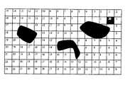
航行体積計算ユニット33が、すべてのボクセルに目標までの距離をラベルによって表示する。図2は単一のスライスに対する距離ラベルの二次元表現を示す。目標は点Gである。図2の具体例では、ボクセルを横切る波頭伝搬手法が用いられる。効率のため、マンハッタン(街区)距離のような距離が格子上に定められている。「障害物」の一部でない航行体積内の各々のボクセルには、目標までの整数距離がラベル表示されている。障害物を含んでいるボクセルは、ラベル表示されていない。これは、処理されていないすべての隣接したボクセルに対して繰り返され、その結果、「波頭」の処理が行われる。波頭の新しい隣がラベル表示できないときに、距離のラベル表示が終了する。
【0020】
一旦、航行体積が作成されれば、分割されたモデルのスライスを解剖学的なスライスであるかのように表示することができる。
操作者5は始点も選択する。体積内の選択された始点から目標までの提案された観察位置経路は経路計算ユニット35によって、従来の方法により、好ましくはメモリ10に記憶された航行体積の値に対して最急降下法を用いて計算される。経路計算ユニット35は、各々の始点から目標点までの距離を計算して、その距離を操作者5に表示することもできる。図3は2つの始点からの計算された経路を示す。
【0021】
経路円滑化ユニット37は従来の円滑化手法を用いて、始点と目標との間の選択された経路点を結合する滑らかな飛行経路を計算する。経路計算ユニット35は目標に向かって動くときに小さなステップを発生するので、観察位置経路上の点の数は典型的には、円滑化の前の1/2又は1/3に減少する。
一旦、観察位置経路が作成されると、操作者5は表現器29に送られた適当な信号によって、計算された観察位置経路に沿って始動、停止及び歩進を行うことができる。
[表示−表現]
表現器29はいくつかの異なる代替表示を用いてもよい。
【0022】
1.単一三次元画像
被検体3の内部構造の表面表現は、市販されているハードウェアを用いて表現することができる。大きな取り囲んでいる組織(例えば、皮膚)の透明な表現により、上述の「関連出願」の欄に挙げた「組織写像」に記述されているように、ユーザに三次元の背景を示すと共に、より深い構造の障害のないビューが得られる。
【0023】
2.立体
立体的なビューを用いることにより、立体−三次元の関係の認識を強化することができる。このためには、2つの別個の画像が操作者5に与えられなければならない。1つは左目のビューに対応し、1つは右目のビューに対応する。
3.分割画面
表現器29によって、表示装置39に2つのビューが同時に表示される。1つの画像は、操作者5が選択した観察位置からのものであり、これは写像として作用する被検体3の全体参照ビューとしての役目を果たす。第2の画像は腔内の観察位置からのものである。
【0024】
4.現在位置
作成された観察位置経路に沿って動く観察位置からの画像が表示されている間に、操作者5はグラフィック表示装置31上の「現在位置」ボタンを押すことができる。これにより、現在の内部画像は概観画像に切り替わり、記号は前の内部画像の内部観察位置の位置を示す。
【0025】
5.断面スライス上のカメラ追跡
表現器29によって作成された表示装置39上のもう1つの窓には、取得ユニット21によって取得されたもとのCT又はMRIスライス上の記号で現在の観察位置が示される。これにより、慣れた横断面画像を見て位置を突き止めることができる。
[実験結果]
被検者の部位について仮想腔検査システムの試験を行った。
【0026】
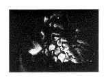
図4では、X線コンピュータ断層撮影(CT)装置を取得ユニット21として用いることにより、被検体3の内部構造の画像情報を取得した。表面抽出器25は、60000個の三角形で記述される表面を抽出した。図4のビューは、結腸を通る観察位置経路に沿った観察位置からのものである。このように観察位置を選択することにより、従来の内視鏡が模擬される。
【0027】
図5は、結腸の拡大全体図を示す「写像」画像であり、図4の画像を作成する際に使用された観察位置を示す記号として円筒が用いられている。この「写像」画像は、表現器29によって同時に作成されて、表示装置39に表示される。これにより、図4の模擬された内視鏡のビューの位置を突き止めることができる。
本発明は、被検者の頭蓋、脳血管及び大動脈にも用いられ、すべてについて良好な画像が得られた。本発明により、医学的に重要な構造、例えば血管内の斑、消化管内のポリープの増強された可視化が非侵襲的に得られるので、重症となるおそれのある病気の早期の検出及び治療が可能となる。
【0028】
本発明は、死体又は無生物にも用いることができる。必要とされるのは、その内部構造のイメージング情報のみである。これらは、上述のように取得してもよいし、又はCAD/CAM法により合成してもよい。
イメージング情報は、種々の形式で与えることができ、上述のような処理のすべてを必要とするわけではない。例えば、イメージング情報は分割された情報として既に与えられていてもよく、この場合には、分割ユニット23は不要となる。同様に、イメージング情報が表面として与えられているならば、表面抽出器25は不要となる。又、表面も既に間引かれていてもよく、これにより、間引き器27を削除することができる。
【0029】
本発明によって作成される内部ビューは、内視鏡のような腔検査装置で得ることができるビューの形式を模擬する。本当の内視鏡のビューと比べて、本発明には、次のような利点がある。
1.視野を含むすべての仮想カメラ・パラメータの対話形制御。
2.臓器の壁を通過することにより、隣接した組織を見ることができる。
【0030】
3.内部画像腔の観察位置の三次元位置を突き止めることができる。
4.コンピュータで生成された経路に沿ったユーザ制御の移動。
5.無限の被写界深度。
本発明のいくつかの現在好ましい実施例を詳細に説明してきたが、当業者には多くの改変及び変更が明らかとなる。従って、特許請求の範囲は、本発明の要旨に入るこのような改変及び変更をすべて包含するように記述してあることが理解されるはずである。
【図面の簡単な説明】
【図1】本発明のシステムの概略ブロック図である。
【図2】本発明の経路計画で用いるための二次元(2D)距離のラベル表示図である。
【図3】本発明の一実施例による経路計画図である。
【図4】コンピュータによって作成された被検体の結腸の内側のビューを表示装置上に表した画像の写真を示す図である。
【図5】図4の画像の観察位置を円筒形の記号で示すように作成された全体の「写像画像」である。
【符号の説明】
5 操作者
10 メモリ
31 グラフィック・インタフェース
33 航行体積計算ユニット
35 経路計算ユニット
37 経路円滑化ユニット
39 表示装置[0001]
[Related Applications]
No. 07 / 815,772, filed Jan. 2, 1992 by Jonathan A. Zage and William J. Schroeder. A Method for Reducing the Complexity of a Polygonal Mesh "and US by William E. Lorensen, filed Oct. 28, 1993. Patent Application No. 08 / 144,270, “Geometric Clipping Using Boolean Textures” (“Tissue Mapping” (T Related to the xture Mapping)). Both of these patents are assigned to the assignee of the present invention.
[0002]
[Industrial application fields]
The present invention relates to visualization of conduits in solids, and more particularly, to non-invasively simulating views from within a conduit from imaging data.
[0003]
[Prior art]
It may be necessary to obtain a view of the conduit through the solid object from an observation location within the conduit. If the subject is a patient, it is necessary to obtain an occlusion or tissue view in the colon, intestine, bronchi, artery, etc. An endoscope is a device that provides a real-time, high-resolution view of the hollow organs and cavities present inside the human body. Most endoscopy is non-invasive, but the procedure still requires sedation or anesthesia to reduce patient discomfort.
[0004]
An internal observation device similar to an endoscope can be used in a non-medical environment to observe a conduit in a solid structure. In some of these devices, the conduit or cavity does not have an opening to the outside, or a continuous opening to the outside is not large enough to accept the internal observation device. I can't see it.
Another problem with internal observation devices is that the field of view is limited to a small area inside the conduit. By determining the exact location within the subject, it is very difficult to correlate the image from the internal imaging device with the large tissue of the subject.
[0005]
To determine the location within the subject, the internal anatomical structure of the subject has been displayed using X-ray computed tomography (CT) and magnetic resonance imaging (MRI) . These methods are non-destructive / non-invasive imaging techniques. Typically, these have been used to supplement the image obtained by the internal imaging device to correlate the image being observed with the position within the subject.
[0006]
In a medical environment, a radiologist typically looks at a two-dimensional (2D (two-dimensional)) cross-section to create a mental image of a three-dimensional structure, and the image from within the conduit is then three-dimensional Correlate with position. However, if the subject has a complicated internal structure, for example, the tubular tissue in the body crosses the cross section back and forth repeatedly.
There is a current need for a device that can non-invasively display an image of a solid internal conduit and indicate where in the subject the view has been acquired.
[0007]
OBJECT OF THE INVENTION
One object of the present invention is to provide a display system that non-invasively obtains an image representing an observation position of an internal image with respect to the entire subject together with an image of a cavity in the subject.
Another object of the present invention is to provide a system that allows an operator to see the structure and surface in the cavity of a subject that does not have an opening to the outside of the subject.
[0008]
SUMMARY OF THE INVENTION
The present invention provides both types of views, an internal “virtual endoscope” view and a large overall view showing the instantaneous position of the endoscope.
The features of the invention believed to be novel are set forth with particularity in the appended claims. However, the structure and method of operation of the present invention, as well as other objects and advantages of the present invention, can best be understood by referring to the following description in conjunction with the drawings.
[0009]
【Example】
The present invention allows visualization of the conduits within the subject and the exploration of surfaces and structures within these conduits.
As shown in FIG. 1, the virtual cavity inspection system according to the present invention includes several sub-systems as follows.
[0010]
1. An
[0011]
2. A
3. A surface extractor 25 that creates a polygonal model of each selected tissue.
4). A
[0012]
5). A functionally divided memory for storing imaging information.
6). A
[Acquire Image]
By using X-ray computed tomography (CT), magnetic resonance imaging (MRI), or an ultrasound system as the
[Split]
The imaging information stored in the
[Surface extractor]
Once the voxels of image information have been segmented and labeled with tissue / organ identifiers, the volume from the
[0013]
In the progressive cube method, linear interpolation is used to locate the tissue boundary within a “cube” defined by eight adjacent voxels by locating the identified tissue surface points. A unit vector perpendicular to the surface is also obtained for each vertex of the triangle from the gradient of the voxel data. For endoscopic applications, surfaces defined by triangles are preferred over point and direct volume representations. This is because re-interpolation of the volume data is too expensive from a computational point of view for the desired interactive representation speed.
[0014]
Since many triangles are often required to create a surface model, a
[0015]
Another way of displaying the model was granted on 12 January 1988 and assigned to the assignee of the present invention Harvey E. Klein, Ziegwald Rutke and William E. Lorensen (Harvey E. Cline). U.S. Pat. No. 4,719,585, Siegwald Ludke and William E. Lorensen, “Cube Splitting System and Method for Displaying Surface Structures Included in Solid Internal Regions” (Dividing Cubes System and Method). for the Display of Surface Structures Contained With the the Interior Region of a Solid Body ("Diving Cubes") It is described in). This patent is to be referred to here. This method produces a surface that begins with volume data and is described by a number of point vectors and normal vectors associated with each point, rather than a polygon. The “cubic division” method has been used to display surfaces contained within volumetric data.
[0016]
Decimation cannot be used for displays that require regular spacing information, such as point displays and normal displays.
The thinned image information from the thinning
[Virtual camera observation position]
The present invention can select an image observation position of a three-dimensional surface model or a series of image observation positions by using any of three methods. These observation positions are collectively referred to as an observation position path.
[0017]
In the first method, an operator controls the image observation position with a
[0018]
The second method uses a computer animation method called key framing. The
[Create route plan]
Crossing the hollow organ that the
[0019]
This approach automatically finds a path through the conduit. The
The navigation
[0020]
Once the navigation volume is created, the segmented model slices can be displayed as if they were anatomical slices.
The
[0021]
The
Once the observation position path is created, the
[Display-Representation]
The
[0022]
1. The surface representation of the internal structure of the single three-dimensional image subject 3 can be represented using commercially available hardware. A transparent representation of the large surrounding tissue (eg skin) presents the user with a three-dimensional background as described in the “Tissue Mapping” listed in the “Related Applications” section above, and more A deep structure free view is obtained.
[0023]
2. By using a stereoscopic view, recognition of a stereoscopic-three-dimensional relationship can be enhanced. For this, two separate images must be given to the
3. Two views are simultaneously displayed on the
[0024]
4). The
[0025]
5). Another window on the
[Experimental result]
The test of the virtual cavity inspection system was performed on the subject's site.
[0026]
In FIG. 4, image information of the internal structure of the subject 3 is acquired by using an X-ray computed tomography (CT) apparatus as the
[0027]
FIG. 5 is a “mapped” image showing an enlarged overall view of the colon, and a cylinder is used as a symbol indicating the observation position used when the image of FIG. 4 is created. This “mapped” image is created simultaneously by the
The present invention was also applied to the subject's skull, cerebral blood vessels and aorta, and good images were obtained for all of them. The present invention provides non-invasive visualization of medically important structures such as plaques in blood vessels and polyps in the gastrointestinal tract, enabling early detection and treatment of potentially serious diseases It becomes.
[0028]
The present invention can also be used for corpses or inanimate objects. All that is required is imaging information of its internal structure. These may be obtained as described above or may be synthesized by CAD / CAM methods.
Imaging information can be provided in a variety of forms and does not require all of the processing described above. For example, the imaging information may already be given as divided information, and in this case, the dividing
[0029]
The internal view created by the present invention mimics the type of view that can be obtained with a cavity inspection device such as an endoscope. Compared to a true endoscopic view, the present invention has the following advantages.
1. Interactive control of all virtual camera parameters including field of view.
2. By passing through the organ wall, adjacent tissue can be seen.
[0030]
3. The three-dimensional position of the observation position of the internal image cavity can be determined.
4). User-controlled movement along computer-generated paths.
5). Infinite depth of field.
While several presently preferred embodiments of the present invention have been described in detail, many modifications and changes will become apparent to those skilled in the art. Accordingly, it is to be understood that the claims are intended to cover all such modifications and changes as fall within the spirit of the invention.
[Brief description of the drawings]
FIG. 1 is a schematic block diagram of a system of the present invention.
FIG. 2 is a two-dimensional (2D) distance label display diagram for use in the route planning of the present invention.
FIG. 3 is a route plan diagram according to one embodiment of the present invention.
FIG. 4 is a view showing a photograph of an image showing a view inside a colon of a subject created by a computer on a display device;
5 is an entire “mapped image” created so that the observation position of the image of FIG. 4 is indicated by a cylindrical symbol.
[Explanation of symbols]
5
Claims (6)
Translated fromJapanese(b) 前記画像情報の三次元の表面モデルを作成する工程と、
(c) 内腔内で始点観察位置を選択する工程と、
(d) 前記内腔内で目標観察位置を選択する工程と、
(e) 前記始点と前記目標位置とを結合している観察位置経路であって、障害物の周りの観察位置経路を計算する工程と、
(f) 前記観察位置経路に沿った観察位置を有している複数の内部画像を作成する工程と、
(g) 内視鏡を模擬するように、前記観察位置経路に沿った位置に従って順次画像を表示する工程とを備え、
前記観察位置経路を計算する工程は、
(e1) 前記表面モデルの各々のボクセルから前記目標位置までの距離であって、障害物の周りを通る距離を計算する工程と、
(e2) 各々のボクセルに該ボクセルの計算された距離をラベル表示する工程と、
(e3) 前記始点を含んでいるボクセルを現在のボクセルとして設定する工程と、
(e4) 前記現在のボクセルを前記観察位置経路に付け加える工程と、
(e5) 前記現在のボクセルに隣接したボクセルであって、最低のラベル表示された距離値を有しているボクセルを確定する工程と、
(e6) 前記最低のラベル表示された距離値を有しているボクセルを前記現在のボクセルに設定する工程と、
(e7) 前記目標を含んでいるボクセルに達するまで、工程(e4)から工程(e6)を繰り返す工程とを含んでいる内視鏡を模擬する方法。(A) obtaining image information of the internal structure of the subject stored in the memory in advance;
(B) creating a three-dimensional surface model of the image information;
(C) selecting a starting point observation position within the lumen;
(D) selecting a target observation position within the lumen;
(E) calculating an observation position path around the obstacle, the observation position path connecting the start point and the target position;
(F) creating a plurality of internal images having observation positions along the observation position path;
(G) sequentially displaying images according to positions along the observation position path so as to simulate an endoscope,
The step of calculating the observation position path includes:
(E1) calculating a distance from each voxel of the surface model to the target position and passing around an obstacle;
(E2) labeling each voxel with the calculated distance of the voxel;
(E3) setting a voxel including the start point as a current voxel;
(E4) adding the current voxel to the observation position path;
(E5) determining a voxel that is adjacent to the current voxel and has the lowest labeled distance value;
(E6) setting the voxel having the lowest labeled distance value as the current voxel;
(E7) A method of simulating an endoscope including steps (e4) to (e6) until a voxel including the target is reached.
(a) 画像情報を記憶するメモリと、
(b) 該メモリに接続されており、観察位置経路に沿った選択された観察位置から見た前記メモリに記憶された画像情報を表示する三次元のモデル表示手段と、
(c) 始点観察位置及び目標観察位置を画定するために操作者と対話するグラフィック・インタフェースと、
(d) 前記メモリに接続されている航行体積計算ユニットであって、各々のボクセルから前記腔を通って前記目標観察位置までの距離を決定すると共に、そのボクセルに対応する距離がそれぞれにラベル表示されたボクセルを有している航行体積を形成する航行体積計算ユニットと、
(e) 前記メモリに接続されている経路計算ユニットであって、前記観察位置経路である前記始点観察位置と前記目標観察位置との間の最短距離を決定すると共に、前記経路を前記メモリに記憶して、前記三次元のモデル表示手段が計算された前記観察位置経路に沿った点から見た一連の画像を作成できるようにする経路計算ユニットとを備えた被検体の内腔のビューを得るための仮想検査システム。A virtual examination system for obtaining a view of a lumen of a subject,
(A) a memory for storing image information;
(B) a three-dimensional model display means connected to the memory for displaying image information stored in the memory viewed from a selected observation position along the observation position path;
(C) a graphic interface for interacting with an operator to define a starting point observation position and a target observation position;
(D) A navigation volume calculation unit connected to the memory, wherein the distance from each voxel through the cavity to the target observation position is determined, and the distance corresponding to the voxel is displayed on each label A navigation volume calculation unit for forming a navigation volume having the voxels arranged;
(E) a path calculation unit connected to the memory, and determines the shortest distance between the starting observation position and the target observation position, which is the observation position path, and stores the path in the memory And obtaining a view of the lumen of the subject provided with a path calculation unit that enables the three-dimensional model display means to create a series of images viewed from the points along the calculated observation position path. Virtual inspection system for.
前記経路計算ユニットは、前記始点観察位置、前記目標観察位置及び中間のキー・フレームを円滑化された観察位置経路に当てはめる、請求項2に記載の仮想検査システム。The graphic interface is capable of interacting with an operator to select a position through which the observation position path is to pass and is a key frame;
The virtual inspection system according to claim 2, wherein the path calculation unit applies the start point observation position, the target observation position, and an intermediate key frame to a smoothed observation position path .
前記三次元のモデル表示手段は、写像画像として作用するように、前記観察位置経路に沿った観察位置で作成された内部画像よりも実質的に大きな視野を有しているもう1つの画像を作成するとともに、現在表示される前記内部画像を作成するために用いられている観察位置を示す写像画像上の任意の記号を表示する、請求項2に記載の仮想検査システム。The graphic interface allows selection of an observation position outside the observation position path;
Model display means of the three-dimensional, so as to act as a map image,theother Tsunoeimagehaving a substantially larger field of view than the internal image created by the viewing position along the observation position pathThe virtual inspection system according to claim 2, wherein an arbitrary symbol on the mapped image indicating the observation position used to create the internal image that is currently displayed is displayed .
Applications Claiming Priority (2)
| Application Number | Priority Date | Filing Date | Title |
|---|---|---|---|
| US08/344,445US5611025A (en) | 1994-11-23 | 1994-11-23 | Virtual internal cavity inspection system |
| US08/344445 | 1994-11-23 |
Publications (2)
| Publication Number | Publication Date |
|---|---|
| JPH08252217A JPH08252217A (en) | 1996-10-01 |
| JP3874826B2true JP3874826B2 (en) | 2007-01-31 |
Family
ID=23350583
Family Applications (1)
| Application Number | Title | Priority Date | Filing Date |
|---|---|---|---|
| JP30405995AExpired - Fee RelatedJP3874826B2 (en) | 1994-11-23 | 1995-11-22 | Method for simulating an endoscope and virtual examination system for obtaining a view of the lumen of a subject |
Country Status (5)
| Country | Link |
|---|---|
| US (1) | US5611025A (en) |
| JP (1) | JP3874826B2 (en) |
| CN (1) | CN1054921C (en) |
| DE (1) | DE19543410B4 (en) |
| IL (1) | IL116011A (en) |
Families Citing this family (179)
| Publication number | Priority date | Publication date | Assignee | Title |
|---|---|---|---|---|
| FR2652928B1 (en) | 1989-10-05 | 1994-07-29 | Diadix Sa | INTERACTIVE LOCAL INTERVENTION SYSTEM WITHIN A AREA OF A NON-HOMOGENEOUS STRUCTURE. |
| AU675077B2 (en) | 1992-08-14 | 1997-01-23 | British Telecommunications Public Limited Company | Position location system |
| US5694530A (en)* | 1994-01-18 | 1997-12-02 | Hitachi Medical Corporation | Method of constructing three-dimensional image according to central projection method and apparatus for same |
| DE69531994T2 (en) | 1994-09-15 | 2004-07-22 | OEC Medical Systems, Inc., Boston | SYSTEM FOR POSITION DETECTION BY MEANS OF A REFERENCE UNIT ATTACHED TO A PATIENT'S HEAD FOR USE IN THE MEDICAL AREA |
| US5920319A (en)* | 1994-10-27 | 1999-07-06 | Wake Forest University | Automatic analysis in virtual endoscopy |
| US6694163B1 (en) | 1994-10-27 | 2004-02-17 | Wake Forest University Health Sciences | Method and system for producing interactive, three-dimensional renderings of selected body organs having hollow lumens to enable simulated movement through the lumen |
| US5782762A (en)* | 1994-10-27 | 1998-07-21 | Wake Forest University | Method and system for producing interactive, three-dimensional renderings of selected body organs having hollow lumens to enable simulated movement through the lumen |
| US7154506B2 (en)* | 1996-02-08 | 2006-12-26 | Palm Charles S | 3D stereo browser for the internet |
| US7190371B2 (en) | 1996-02-08 | 2007-03-13 | Palm Charles S | 3D stereo browser for the internet |
| EP0880756A4 (en) | 1996-02-08 | 1999-04-28 | Synthonics Inc | 3d stereo browser for the internet |
| JP3770280B2 (en)* | 1996-03-29 | 2006-04-26 | 株式会社日立メディコ | 3D image display method and apparatus |
| US6167296A (en)* | 1996-06-28 | 2000-12-26 | The Board Of Trustees Of The Leland Stanford Junior University | Method for volumetric image navigation |
| US6040841A (en)* | 1996-08-02 | 2000-03-21 | Microsoft Corporation | Method and system for virtual cinematography |
| US6343936B1 (en) | 1996-09-16 | 2002-02-05 | The Research Foundation Of State University Of New York | System and method for performing a three-dimensional virtual examination, navigation and visualization |
| US7486811B2 (en)* | 1996-09-16 | 2009-02-03 | The Research Foundation Of State University Of New York | System and method for performing a three-dimensional virtual examination of objects, such as internal organs |
| US6331116B1 (en) | 1996-09-16 | 2001-12-18 | The Research Foundation Of State University Of New York | System and method for performing a three-dimensional virtual segmentation and examination |
| US7194117B2 (en)* | 1999-06-29 | 2007-03-20 | The Research Foundation Of State University Of New York | System and method for performing a three-dimensional virtual examination of objects, such as internal organs |
| US5971767A (en)* | 1996-09-16 | 1999-10-26 | The Research Foundation Of State University Of New York | System and method for performing a three-dimensional virtual examination |
| US8682045B2 (en)* | 1997-02-25 | 2014-03-25 | Wake Forest University Health Sciences | Virtual endoscopy with improved image segmentation and lesion detection |
| US6346940B1 (en) | 1997-02-27 | 2002-02-12 | Kabushiki Kaisha Toshiba | Virtualized endoscope system |
| US6272370B1 (en) | 1998-08-07 | 2001-08-07 | The Regents Of University Of Minnesota | MR-visible medical device for neurological interventions using nonlinear magnetic stereotaxis and a method imaging |
| US6246784B1 (en) | 1997-08-19 | 2001-06-12 | The United States Of America As Represented By The Department Of Health And Human Services | Method for segmenting medical images and detecting surface anomalies in anatomical structures |
| US6226548B1 (en) | 1997-09-24 | 2001-05-01 | Surgical Navigation Technologies, Inc. | Percutaneous registration apparatus and method for use in computer-assisted surgical navigation |
| US6021343A (en) | 1997-11-20 | 2000-02-01 | Surgical Navigation Technologies | Image guided awl/tap/screwdriver |
| US6369812B1 (en) | 1997-11-26 | 2002-04-09 | Philips Medical Systems, (Cleveland), Inc. | Inter-active viewing system for generating virtual endoscopy studies of medical diagnostic data with a continuous sequence of spherical panoramic views and viewing the studies over networks |
| US6348058B1 (en) | 1997-12-12 | 2002-02-19 | Surgical Navigation Technologies, Inc. | Image guided spinal surgery guide, system, and method for use thereof |
| DE69937651T2 (en) | 1998-02-23 | 2008-06-19 | Algotec Systems Ltd. | System and method for ray tracing |
| JP2002504385A (en) | 1998-02-23 | 2002-02-12 | アルゴテック システムズ リミテッド | Automatic route planning method |
| US6463317B1 (en) | 1998-05-19 | 2002-10-08 | Regents Of The University Of Minnesota | Device and method for the endovascular treatment of aneurysms |
| US6118845A (en) | 1998-06-29 | 2000-09-12 | Surgical Navigation Technologies, Inc. | System and methods for the reduction and elimination of image artifacts in the calibration of X-ray imagers |
| US6477400B1 (en) | 1998-08-20 | 2002-11-05 | Sofamor Danek Holdings, Inc. | Fluoroscopic image guided orthopaedic surgery system with intraoperative registration |
| CA2352671A1 (en) | 1998-11-25 | 2000-06-08 | Wake Forest University | Virtual endoscopy with improved image segmentation and lesion detection |
| US6470207B1 (en) | 1999-03-23 | 2002-10-22 | Surgical Navigation Technologies, Inc. | Navigational guidance via computer-assisted fluoroscopic imaging |
| US6491699B1 (en)* | 1999-04-20 | 2002-12-10 | Surgical Navigation Technologies, Inc. | Instrument guidance method and system for image guided surgery |
| JP2001008232A (en)* | 1999-06-25 | 2001-01-12 | Matsushita Electric Ind Co Ltd | Omnidirectional video output method and device |
| US7366562B2 (en) | 2003-10-17 | 2008-04-29 | Medtronic Navigation, Inc. | Method and apparatus for surgical navigation |
| US6474341B1 (en) | 1999-10-28 | 2002-11-05 | Surgical Navigation Technologies, Inc. | Surgical communication and power system |
| US11331150B2 (en) | 1999-10-28 | 2022-05-17 | Medtronic Navigation, Inc. | Method and apparatus for surgical navigation |
| US8644907B2 (en) | 1999-10-28 | 2014-02-04 | Medtronic Navigaton, Inc. | Method and apparatus for surgical navigation |
| US6499488B1 (en) | 1999-10-28 | 2002-12-31 | Winchester Development Associates | Surgical sensor |
| US6493573B1 (en) | 1999-10-28 | 2002-12-10 | Winchester Development Associates | Method and system for navigating a catheter probe in the presence of field-influencing objects |
| US8239001B2 (en) | 2003-10-17 | 2012-08-07 | Medtronic Navigation, Inc. | Method and apparatus for surgical navigation |
| US6381485B1 (en) | 1999-10-28 | 2002-04-30 | Surgical Navigation Technologies, Inc. | Registration of human anatomy integrated for electromagnetic localization |
| US6235038B1 (en) | 1999-10-28 | 2001-05-22 | Medtronic Surgical Navigation Technologies | System for translation of electromagnetic and optical localization systems |
| US6725080B2 (en) | 2000-03-01 | 2004-04-20 | Surgical Navigation Technologies, Inc. | Multiple cannula image guided tool for image guided procedures |
| US6535756B1 (en) | 2000-04-07 | 2003-03-18 | Surgical Navigation Technologies, Inc. | Trajectory storage apparatus and method for surgical navigation system |
| WO2001093745A2 (en)* | 2000-06-06 | 2001-12-13 | The Research Foundation Of State University Of New York | Computer aided visualization, fusion and treatment planning |
| US7085400B1 (en) | 2000-06-14 | 2006-08-01 | Surgical Navigation Technologies, Inc. | System and method for image based sensor calibration |
| AU2002211391A1 (en) | 2000-10-02 | 2002-04-15 | The Research Foundation Of State University Of New York | Enhanced virtual navigation and examination |
| DE10102477A1 (en) | 2001-01-19 | 2002-07-25 | Storz Endoskop Gmbh Schaffhaus | Anastomosis of two ends of a blood vessel using laser surgery, has light guiding instrument that directs light from a source along an optical fiber to the joint where the light is deflected outwards to weld the tissue together |
| US7630750B2 (en)* | 2001-02-05 | 2009-12-08 | The Research Foundation For The State University Of New York | Computer aided treatment planning |
| EP1393259B1 (en)* | 2001-05-11 | 2018-06-13 | Koninklijke Philips N.V. | Method, system and computer program for producing a medical report |
| EP1393260A1 (en)* | 2001-05-15 | 2004-03-03 | Koninklijke Philips Electronics N.V. | Analysis of a multi-dimensional data set |
| US6636757B1 (en) | 2001-06-04 | 2003-10-21 | Surgical Navigation Technologies, Inc. | Method and apparatus for electromagnetic navigation of a surgical probe near a metal object |
| JP4584575B2 (en)* | 2001-07-06 | 2010-11-24 | クゥアルコム・インコーポレイテッド | Image processing method for interacting with 3D surface displayed in 3D image |
| US7596256B1 (en) | 2001-09-14 | 2009-09-29 | The Research Foundation For The State University Of New York | Computer assisted detection of lesions in volumetric medical images |
| US7324104B1 (en) | 2001-09-14 | 2008-01-29 | The Research Foundation Of State University Of New York | Method of centerline generation in virtual objects |
| US6711231B2 (en)* | 2001-12-10 | 2004-03-23 | Ge Medical Systems Global Technology Company, Llc | Methods and apparatus to assist and facilitate vessel analysis |
| WO2003051200A2 (en)* | 2001-12-14 | 2003-06-26 | Koninklijke Philips Electronics N.V. | Method, system and computer program of visualizing the surface texture of the wall of an internal hollow organ of a subject based on a volumetric scan thereof |
| KR100439756B1 (en)* | 2002-01-09 | 2004-07-12 | 주식회사 인피니트테크놀로지 | Apparatus and method for displaying virtual endoscopy diaplay |
| US6947786B2 (en) | 2002-02-28 | 2005-09-20 | Surgical Navigation Technologies, Inc. | Method and apparatus for perspective inversion |
| WO2003083781A1 (en) | 2002-03-29 | 2003-10-09 | Koninklijke Philips Electronics N.V. | Method, system and computer program for stereoscopic viewing of 3d medical images |
| US6990368B2 (en) | 2002-04-04 | 2006-01-24 | Surgical Navigation Technologies, Inc. | Method and apparatus for virtual digital subtraction angiography |
| EP1500054A1 (en)* | 2002-04-12 | 2005-01-26 | Koninklijke Philips Electronics N.V. | Graphical apparatus and method for tracking image volume review |
| US7998062B2 (en) | 2004-03-29 | 2011-08-16 | Superdimension, Ltd. | Endoscope structures and techniques for navigating to a target in branched structure |
| US7260250B2 (en)* | 2002-09-30 | 2007-08-21 | The United States Of America As Represented By The Secretary Of The Department Of Health And Human Services | Computer-aided classification of anomalies in anatomical structures |
| US7599730B2 (en) | 2002-11-19 | 2009-10-06 | Medtronic Navigation, Inc. | Navigation system for cardiac therapies |
| US7697972B2 (en) | 2002-11-19 | 2010-04-13 | Medtronic Navigation, Inc. | Navigation system for cardiac therapies |
| US7202869B2 (en)* | 2003-01-07 | 2007-04-10 | Lucasfilm Entertainment Company Ltd. | System and method of creating and animating a computer-generated image of a creature |
| US7081088B2 (en)* | 2003-01-30 | 2006-07-25 | Siemens Corporate Research, Inc. | Method and apparatus for automatic local path planning for virtual colonoscopy |
| US7660623B2 (en) | 2003-01-30 | 2010-02-09 | Medtronic Navigation, Inc. | Six degree of freedom alignment display for medical procedures |
| US7542791B2 (en) | 2003-01-30 | 2009-06-02 | Medtronic Navigation, Inc. | Method and apparatus for preplanning a surgical procedure |
| US7304644B2 (en)* | 2003-03-12 | 2007-12-04 | Siemens Medical Solutions Usa, Inc. | System and method for performing a virtual endoscopy |
| AU2003901625A0 (en)* | 2003-03-28 | 2003-05-01 | Commonwealth Scientific And Industrial Research Organisation | Combining front propagation with shape knowledge for accurate curvilinear modelling |
| US7570791B2 (en) | 2003-04-25 | 2009-08-04 | Medtronic Navigation, Inc. | Method and apparatus for performing 2D to 3D registration |
| US7457444B2 (en)* | 2003-05-14 | 2008-11-25 | Siemens Medical Solutions Usa, Inc. | Method and apparatus for fast automatic centerline extraction for virtual endoscopy |
| US7822461B2 (en)* | 2003-07-11 | 2010-10-26 | Siemens Medical Solutions Usa, Inc. | System and method for endoscopic path planning |
| US7313430B2 (en) | 2003-08-28 | 2007-12-25 | Medtronic Navigation, Inc. | Method and apparatus for performing stereotactic surgery |
| EP2316328B1 (en) | 2003-09-15 | 2012-05-09 | Super Dimension Ltd. | Wrap-around holding device for use with bronchoscopes |
| EP2113189B1 (en) | 2003-09-15 | 2013-09-04 | Covidien LP | System of accessories for use with bronchoscopes |
| US7835778B2 (en)* | 2003-10-16 | 2010-11-16 | Medtronic Navigation, Inc. | Method and apparatus for surgical navigation of a multiple piece construct for implantation |
| US7840253B2 (en) | 2003-10-17 | 2010-11-23 | Medtronic Navigation, Inc. | Method and apparatus for surgical navigation |
| CA2543635A1 (en)* | 2003-11-03 | 2005-08-11 | Bracco Imaging S.P.A. | System and methods for screening a luminal organ "lumen viewer" |
| JP3847744B2 (en)* | 2003-11-04 | 2006-11-22 | オリンパス株式会社 | Insertion support system |
| US20060036162A1 (en)* | 2004-02-02 | 2006-02-16 | Ramin Shahidi | Method and apparatus for guiding a medical instrument to a subsurface target site in a patient |
| US8764725B2 (en) | 2004-02-09 | 2014-07-01 | Covidien Lp | Directional anchoring mechanism, method and applications thereof |
| US20070198178A1 (en)* | 2004-03-31 | 2007-08-23 | Trimby Martin W | Pathfinding system |
| CN1333360C (en)* | 2004-04-28 | 2007-08-22 | 复旦大学 | Center line automatic locating method of virtual endoscope system |
| US7567834B2 (en) | 2004-05-03 | 2009-07-28 | Medtronic Navigation, Inc. | Method and apparatus for implantation between two vertebral bodies |
| ATE484811T1 (en)* | 2004-06-23 | 2010-10-15 | Koninkl Philips Electronics Nv | VIRTUAL ENDOSCOPY |
| US7636595B2 (en) | 2004-10-28 | 2009-12-22 | Medtronic Navigation, Inc. | Method and apparatus for calibrating non-linear instruments |
| CN1779718B (en)* | 2004-11-18 | 2010-11-24 | 中国科学院自动化研究所 | Visibility block rendering device and method for virtual endoscope |
| US7586501B2 (en) | 2005-05-24 | 2009-09-08 | Siemens Medical Solutions Usa, Inc. | Simultaneous projection of multi-branched vessels and their context on a single image |
| US7379062B2 (en)* | 2005-08-01 | 2008-05-27 | Barco Nv | Method for determining a path along a biological object with a lumen |
| JP2007066291A (en)* | 2005-08-02 | 2007-03-15 | Seiko Epson Corp | Image display method, image display apparatus, image display system, server, program, and recording medium |
| US20070046661A1 (en)* | 2005-08-31 | 2007-03-01 | Siemens Medical Solutions Usa, Inc. | Three or four-dimensional medical imaging navigation methods and systems |
| US7623900B2 (en)* | 2005-09-02 | 2009-11-24 | Toshiba Medical Visualization Systems Europe, Ltd. | Method for navigating a virtual camera along a biological object with a lumen |
| US7835784B2 (en) | 2005-09-21 | 2010-11-16 | Medtronic Navigation, Inc. | Method and apparatus for positioning a reference frame |
| DE102005046203B3 (en)* | 2005-09-27 | 2007-01-04 | Siemens Ag | Diagnostic picture data selectively representing method, involves determining three-dimensional picture information, and subdividing determined information into representative and non-representative unit data values |
| US8079957B2 (en)* | 2005-11-18 | 2011-12-20 | Siemens Medical Solutions Usa, Inc. | Synchronized three or four-dimensional medical ultrasound imaging and measurements |
| WO2007064981A2 (en)* | 2005-11-30 | 2007-06-07 | The Research Foundation Of State University Of New York | Reducing false positives of polyp in cad |
| WO2007064980A2 (en)* | 2005-11-30 | 2007-06-07 | The Research Foundation Of State University Of New York | Electronic colon cleansing method for virtual colonoscopy |
| US9168102B2 (en) | 2006-01-18 | 2015-10-27 | Medtronic Navigation, Inc. | Method and apparatus for providing a container to a sterile environment |
| JP4832927B2 (en)* | 2006-03-14 | 2011-12-07 | オリンパスメディカルシステムズ株式会社 | Medical image processing apparatus and medical image processing method |
| US8112292B2 (en) | 2006-04-21 | 2012-02-07 | Medtronic Navigation, Inc. | Method and apparatus for optimizing a therapy |
| US8560047B2 (en) | 2006-06-16 | 2013-10-15 | Board Of Regents Of The University Of Nebraska | Method and apparatus for computer aided surgery |
| JP4738270B2 (en)* | 2006-07-14 | 2011-08-03 | 株式会社日立メディコ | Surgery support device |
| CN100464709C (en)* | 2006-08-03 | 2009-03-04 | 上海交通大学 | A Method for Improving the Visualization of Cavity Viscera Using Virtual Inflation |
| CN100434044C (en)* | 2006-08-03 | 2008-11-19 | 上海交通大学 | A Method of Realizing Virtual Pneumatic Expansion of Pipeline Viscera Using Non-rigid Registration of Feature Points |
| US8660635B2 (en) | 2006-09-29 | 2014-02-25 | Medtronic, Inc. | Method and apparatus for optimizing a computer assisted surgical procedure |
| US20080144901A1 (en)* | 2006-10-25 | 2008-06-19 | General Electric Company | Cartoon-like exaggeration of medical images to emphasize abnormalities |
| US20080117210A1 (en)* | 2006-11-22 | 2008-05-22 | Barco N.V. | Virtual endoscopy |
| US7853058B2 (en)* | 2006-11-22 | 2010-12-14 | Toshiba Medical Visualization Systems Europe, Limited | Determining a viewpoint for navigating a virtual camera through a biological object with a lumen |
| JP2008236195A (en)* | 2007-03-19 | 2008-10-02 | Sony Corp | Imaging block and imaging device |
| US9883818B2 (en) | 2007-06-19 | 2018-02-06 | Accuray Incorporated | Fiducial localization |
| US20090003528A1 (en) | 2007-06-19 | 2009-01-01 | Sankaralingam Ramraj | Target location by tracking of imaging device |
| US8905920B2 (en) | 2007-09-27 | 2014-12-09 | Covidien Lp | Bronchoscope adapter and method |
| WO2009122273A2 (en) | 2008-04-03 | 2009-10-08 | Superdimension, Ltd. | Magnetic interference detection system and method |
| EP2297673B1 (en) | 2008-06-03 | 2020-04-22 | Covidien LP | Feature-based registration method |
| US8218847B2 (en) | 2008-06-06 | 2012-07-10 | Superdimension, Ltd. | Hybrid registration method |
| US8932207B2 (en) | 2008-07-10 | 2015-01-13 | Covidien Lp | Integrated multi-functional endoscopic tool |
| US8165658B2 (en) | 2008-09-26 | 2012-04-24 | Medtronic, Inc. | Method and apparatus for positioning a guide relative to a base |
| US8175681B2 (en) | 2008-12-16 | 2012-05-08 | Medtronic Navigation Inc. | Combination of electromagnetic and electropotential localization |
| EP2381866B1 (en)* | 2008-12-29 | 2017-03-22 | Koninklijke Philips N.V. | Path planning for reducing tissue damage in minimally invasive surgery |
| CN101849843B (en)* | 2009-03-31 | 2013-03-13 | 上海交通大学医学院附属新华医院 | Navigation method of three-dimensional cardiac ultrasonic virtual endoscope |
| US8611984B2 (en) | 2009-04-08 | 2013-12-17 | Covidien Lp | Locatable catheter |
| US8494614B2 (en) | 2009-08-31 | 2013-07-23 | Regents Of The University Of Minnesota | Combination localization system |
| US8494613B2 (en) | 2009-08-31 | 2013-07-23 | Medtronic, Inc. | Combination localization system |
| US8348831B2 (en)* | 2009-12-15 | 2013-01-08 | Zhejiang University | Device and method for computer simulated marking targeting biopsy |
| JP5551955B2 (en)* | 2010-03-31 | 2014-07-16 | 富士フイルム株式会社 | Projection image generation apparatus, method, and program |
| US10582834B2 (en) | 2010-06-15 | 2020-03-10 | Covidien Lp | Locatable expandable working channel and method |
| JP5520804B2 (en)* | 2010-12-20 | 2014-06-11 | 本田技研工業株式会社 | Surface mesh model generating apparatus, surface mesh model generating method and computer program for generating surface mesh model used in calculation of boundary element method |
| US11911117B2 (en) | 2011-06-27 | 2024-02-27 | Board Of Regents Of The University Of Nebraska | On-board tool tracking system and methods of computer assisted surgery |
| US9498231B2 (en) | 2011-06-27 | 2016-11-22 | Board Of Regents Of The University Of Nebraska | On-board tool tracking system and methods of computer assisted surgery |
| CN103764061B (en) | 2011-06-27 | 2017-03-08 | 内布拉斯加大学评议会 | On Tool Tracking System and Computer Assisted Surgery Method |
| EP3689250B1 (en) | 2011-10-17 | 2022-12-07 | BFLY Operations, Inc. | Transmissive imaging and related apparatus and methods |
| RU2606453C2 (en) | 2011-12-03 | 2017-01-10 | Конинклейке Филипс Н.В. | Automatic depth scrolling and orientation adjustment for semi-automated path planning |
| US10127722B2 (en) | 2015-06-30 | 2018-11-13 | Matterport, Inc. | Mobile capture visualization incorporating three-dimensional and two-dimensional imagery |
| US10163261B2 (en)* | 2014-03-19 | 2018-12-25 | Matterport, Inc. | Selecting two-dimensional imagery data for display within a three-dimensional model |
| US10139985B2 (en) | 2012-06-22 | 2018-11-27 | Matterport, Inc. | Defining, displaying and interacting with tags in a three-dimensional model |
| US9786097B2 (en) | 2012-06-22 | 2017-10-10 | Matterport, Inc. | Multi-modal method for interacting with 3D models |
| JP5930539B2 (en)* | 2012-09-12 | 2016-06-08 | 富士フイルム株式会社 | MEDICAL IMAGE DISPLAY DEVICE, METHOD, AND PROGRAM |
| US10105149B2 (en) | 2013-03-15 | 2018-10-23 | Board Of Regents Of The University Of Nebraska | On-board tool tracking system and methods of computer assisted surgery |
| US9459770B2 (en) | 2013-03-15 | 2016-10-04 | Covidien Lp | Pathway planning system and method |
| US9925009B2 (en) | 2013-03-15 | 2018-03-27 | Covidien Lp | Pathway planning system and method |
| US9639666B2 (en) | 2013-03-15 | 2017-05-02 | Covidien Lp | Pathway planning system and method |
| US9667889B2 (en) | 2013-04-03 | 2017-05-30 | Butterfly Network, Inc. | Portable electronic devices with integrated imaging capabilities |
| US10952593B2 (en) | 2014-06-10 | 2021-03-23 | Covidien Lp | Bronchoscope adapter |
| AU2015283946B2 (en) | 2014-07-02 | 2019-09-12 | Covidien Lp | Real-time automatic registration feedback |
| US20160000414A1 (en) | 2014-07-02 | 2016-01-07 | Covidien Lp | Methods for marking biopsy location |
| CN106232010B (en) | 2014-07-02 | 2020-03-31 | 柯惠有限合伙公司 | System and method for detecting trachea |
| US9603668B2 (en) | 2014-07-02 | 2017-03-28 | Covidien Lp | Dynamic 3D lung map view for tool navigation inside the lung |
| US9754367B2 (en) | 2014-07-02 | 2017-09-05 | Covidien Lp | Trachea marking |
| US9770216B2 (en) | 2014-07-02 | 2017-09-26 | Covidien Lp | System and method for navigating within the lung |
| CN106659453B (en) | 2014-07-02 | 2020-05-26 | 柯惠有限合伙公司 | System and method for segmenting lungs |
| US11227427B2 (en) | 2014-08-11 | 2022-01-18 | Covidien Lp | Treatment procedure planning system and method |
| US10426555B2 (en) | 2015-06-03 | 2019-10-01 | Covidien Lp | Medical instrument with sensor for use in a system and method for electromagnetic navigation |
| CN104887175A (en)* | 2015-06-03 | 2015-09-09 | 皖南医学院 | Virtual gastroscopy and diagnosis system |
| US10986990B2 (en) | 2015-09-24 | 2021-04-27 | Covidien Lp | Marker placement |
| US10709352B2 (en) | 2015-10-27 | 2020-07-14 | Covidien Lp | Method of using lung airway carina locations to improve ENB registration |
| US9962134B2 (en) | 2015-10-28 | 2018-05-08 | Medtronic Navigation, Inc. | Apparatus and method for maintaining image quality while minimizing X-ray dosage of a patient |
| US10478254B2 (en) | 2016-05-16 | 2019-11-19 | Covidien Lp | System and method to access lung tissue |
| US10418705B2 (en) | 2016-10-28 | 2019-09-17 | Covidien Lp | Electromagnetic navigation antenna assembly and electromagnetic navigation system including the same |
| US10446931B2 (en) | 2016-10-28 | 2019-10-15 | Covidien Lp | Electromagnetic navigation antenna assembly and electromagnetic navigation system including the same |
| US10615500B2 (en) | 2016-10-28 | 2020-04-07 | Covidien Lp | System and method for designing electromagnetic navigation antenna assemblies |
| US10751126B2 (en) | 2016-10-28 | 2020-08-25 | Covidien Lp | System and method for generating a map for electromagnetic navigation |
| US10638952B2 (en) | 2016-10-28 | 2020-05-05 | Covidien Lp | Methods, systems, and computer-readable media for calibrating an electromagnetic navigation system |
| US10722311B2 (en) | 2016-10-28 | 2020-07-28 | Covidien Lp | System and method for identifying a location and/or an orientation of an electromagnetic sensor based on a map |
| US10792106B2 (en) | 2016-10-28 | 2020-10-06 | Covidien Lp | System for calibrating an electromagnetic navigation system |
| US10517505B2 (en) | 2016-10-28 | 2019-12-31 | Covidien Lp | Systems, methods, and computer-readable media for optimizing an electromagnetic navigation system |
| CN109922753B (en)* | 2016-12-08 | 2023-04-14 | 直观外科手术操作公司 | Systems and methods for navigation in image-guided medical procedures |
| US11219489B2 (en) | 2017-10-31 | 2022-01-11 | Covidien Lp | Devices and systems for providing sensors in parallel with medical tools |
| US11224392B2 (en) | 2018-02-01 | 2022-01-18 | Covidien Lp | Mapping disease spread |
| US11132830B2 (en)* | 2018-03-29 | 2021-09-28 | Biosense Webster (Israel) Ltd. | Static virtual camera positioning |
| US12089902B2 (en) | 2019-07-30 | 2024-09-17 | Coviden Lp | Cone beam and 3D fluoroscope lung navigation |
| CN111000631B (en)* | 2019-12-17 | 2021-04-06 | 上海嘉奥信息科技发展有限公司 | Endoscope simulation method and system based on Unity3D volume rendering |
| US11413097B2 (en) | 2019-12-31 | 2022-08-16 | Biosense Webster (Israel) Ltd. | Three dimensional mapping system for cranial surgical pathways with semi-targets and method |
| US11771505B2 (en) | 2019-12-31 | 2023-10-03 | Biosense Webster (Israel) Ltd. | Three dimensional mapping system for cranial surgical pathways and method |
| CN116153147B (en)* | 2023-02-28 | 2025-02-18 | 中国人民解放军陆军特色医学中心 | 3D-VR binocular stereoscopic vision image construction method and endoscope operation teaching device |
Family Cites Families (11)
| Publication number | Priority date | Publication date | Assignee | Title |
|---|---|---|---|---|
| US4710876A (en)* | 1985-06-05 | 1987-12-01 | General Electric Company | System and method for the display of surface structures contained within the interior region of a solid body |
| US4719585A (en)* | 1985-08-28 | 1988-01-12 | General Electric Company | Dividing cubes system and method for the display of surface structures contained within the interior region of a solid body |
| US4751643A (en)* | 1986-08-04 | 1988-06-14 | General Electric Company | Method and apparatus for determining connected substructures within a body |
| US5233687A (en)* | 1987-03-25 | 1993-08-03 | Xerox Corporation | User interface with multiple workspaces for sharing display system objects |
| FR2636451A1 (en)* | 1988-09-13 | 1990-03-16 | Gen Electric Cgr | METHOD FOR RECONSTRUCTION OF THREE-DIMENSIONAL TREE BY LABELING |
| US4907973A (en)* | 1988-11-14 | 1990-03-13 | Hon David C | Expert system simulator for modeling realistic internal environments and performance |
| US5187658A (en)* | 1990-01-17 | 1993-02-16 | General Electric Company | System and method for segmenting internal structures contained within the interior region of a solid object |
| FR2662525B1 (en)* | 1990-05-25 | 1992-08-28 | Gen Electric Cgr | METHOD FOR VISUALIZATION OF A PART OF THE IMAGE OF A PHYSICAL STRUCTURE. |
| US5287446A (en)* | 1990-10-15 | 1994-02-15 | Sierra On-Line, Inc. | System and methods for intelligent movement on computer displays |
| US5313567A (en)* | 1991-06-13 | 1994-05-17 | At&T Bell Laboratories | Arrangement for determining and displaying volumetric data in an imaging system |
| US5347459A (en)* | 1993-03-17 | 1994-09-13 | National Research Council Of Canada | Real time collision detection |
- 1994
- 1994-11-23USUS08/344,445patent/US5611025A/ennot_activeExpired - Lifetime
- 1995
- 1995-11-15ILIL11601195Apatent/IL116011A/ennot_activeIP Right Cessation
- 1995-11-21DEDE19543410Apatent/DE19543410B4/ennot_activeExpired - Fee Related
- 1995-11-22CNCN95118185.8Apatent/CN1054921C/ennot_activeExpired - Fee Related
- 1995-11-22JPJP30405995Apatent/JP3874826B2/ennot_activeExpired - Fee Related
Also Published As
| Publication number | Publication date |
|---|---|
| CN1054921C (en) | 2000-07-26 |
| IL116011A (en) | 1999-05-09 |
| JPH08252217A (en) | 1996-10-01 |
| CN1135047A (en) | 1996-11-06 |
| IL116011A0 (en) | 1996-01-31 |
| DE19543410A1 (en) | 1996-06-27 |
| US5611025A (en) | 1997-03-11 |
| DE19543410B4 (en) | 2009-06-04 |
Similar Documents
| Publication | Publication Date | Title |
|---|---|---|
| JP3874826B2 (en) | Method for simulating an endoscope and virtual examination system for obtaining a view of the lumen of a subject | |
| Lorensen et al. | The exploration of cross-sectional data with a virtual endoscope | |
| JP4421016B2 (en) | Medical image processing device | |
| KR100701235B1 (en) | 3D Virtual Segmentation and Inspection System and Method | |
| JP5130529B2 (en) | Information processing apparatus and program | |
| US6049622A (en) | Graphic navigational guides for accurate image orientation and navigation | |
| KR100790536B1 (en) | How to create a path through the virtual colon lumen | |
| US5526812A (en) | Display system for enhancing visualization of body structures during medical procedures | |
| JP3117665B2 (en) | Image display method and image display device | |
| WO2015154069A1 (en) | Dynamic and interactive navigation in a surgical environment | |
| JPH11161813A (en) | Operation simulation device | |
| JP2020512089A (en) | Virtual shadows that enhance depth perception | |
| Kutter et al. | Real-time volume rendering for high quality visualization in augmented reality | |
| JP2001276066A (en) | 3D image processing device | |
| Williams et al. | Volumetric curved planar reformation for virtual endoscopy | |
| EP0629963A2 (en) | A display system for visualization of body structures during medical procedures | |
| Bartz et al. | Interactive exploration of extra-and interacranial blood vessels | |
| Shahidi et al. | Surface rendering versus volume rendering in medical imaging: techniques and applications | |
| Robb | Virtual endoscopy: evaluation using the visible human datasets and comparison with real endoscopy in patients | |
| Robb et al. | Patient-specific anatomic models from three dimensional medical image data for clinical applications in surgery and endoscopy | |
| Ramaswamy et al. | Endoscopic exploration and measurement in 3D radiological images | |
| JPH08280710A (en) | Real time medical device,and method to support operator to perform medical procedure on patient | |
| Bartz et al. | Interactive and multi-modal visualization for neuroendoscopic interventions | |
| JP2005349199A (en) | Medical 3D image display and 3D image processing method, computer tomography apparatus, workstation, and computer program product | |
| Toriwaki et al. | Recent progress in medical image processing-Virtualized human body and computer-aided surgery |
Legal Events
| Date | Code | Title | Description |
|---|---|---|---|
| A131 | Notification of reasons for refusal | Free format text:JAPANESE INTERMEDIATE CODE: A131 Effective date:20051220 | |
| A521 | Request for written amendment filed | Free format text:JAPANESE INTERMEDIATE CODE: A523 Effective date:20060310 | |
| A131 | Notification of reasons for refusal | Free format text:JAPANESE INTERMEDIATE CODE: A131 Effective date:20060418 | |
| A521 | Request for written amendment filed | Free format text:JAPANESE INTERMEDIATE CODE: A523 Effective date:20060711 | |
| TRDD | Decision of grant or rejection written | ||
| A01 | Written decision to grant a patent or to grant a registration (utility model) | Free format text:JAPANESE INTERMEDIATE CODE: A01 Effective date:20061003 | |
| A61 | First payment of annual fees (during grant procedure) | Free format text:JAPANESE INTERMEDIATE CODE: A61 Effective date:20061025 | |
| R150 | Certificate of patent or registration of utility model | Free format text:JAPANESE INTERMEDIATE CODE: R150 | |
| FPAY | Renewal fee payment (event date is renewal date of database) | Free format text:PAYMENT UNTIL: 20091102 Year of fee payment:3 | |
| FPAY | Renewal fee payment (event date is renewal date of database) | Free format text:PAYMENT UNTIL: 20101102 Year of fee payment:4 | |
| FPAY | Renewal fee payment (event date is renewal date of database) | Free format text:PAYMENT UNTIL: 20111102 Year of fee payment:5 | |
| FPAY | Renewal fee payment (event date is renewal date of database) | Free format text:PAYMENT UNTIL: 20121102 Year of fee payment:6 | |
| FPAY | Renewal fee payment (event date is renewal date of database) | Free format text:PAYMENT UNTIL: 20121102 Year of fee payment:6 | |
| FPAY | Renewal fee payment (event date is renewal date of database) | Free format text:PAYMENT UNTIL: 20131102 Year of fee payment:7 | |
| LAPS | Cancellation because of no payment of annual fees |