JP3873864B2 - Backup charging circuit - Google Patents
Backup charging circuitDownload PDFInfo
- Publication number
- JP3873864B2 JP3873864B2JP2002304775AJP2002304775AJP3873864B2JP 3873864 B2JP3873864 B2JP 3873864B2JP 2002304775 AJP2002304775 AJP 2002304775AJP 2002304775 AJP2002304775 AJP 2002304775AJP 3873864 B2JP3873864 B2JP 3873864B2
- Authority
- JP
- Japan
- Prior art keywords
- battery
- backup
- voltage
- charging
- circuit
- Prior art date
- Legal status (The legal status is an assumption and is not a legal conclusion. Google has not performed a legal analysis and makes no representation as to the accuracy of the status listed.)
- Expired - Fee Related
Links
Images


Classifications
- H—ELECTRICITY
- H02—GENERATION; CONVERSION OR DISTRIBUTION OF ELECTRIC POWER
- H02J—CIRCUIT ARRANGEMENTS OR SYSTEMS FOR SUPPLYING OR DISTRIBUTING ELECTRIC POWER; SYSTEMS FOR STORING ELECTRIC ENERGY
- H02J7/00—Circuit arrangements for charging or depolarising batteries or for supplying loads from batteries
- H02J7/34—Parallel operation in networks using both storage and other DC sources, e.g. providing buffering
- H02J7/342—The other DC source being a battery actively interacting with the first one, i.e. battery to battery charging
Landscapes
- Engineering & Computer Science (AREA)
- Power Engineering (AREA)
- Charge And Discharge Circuits For Batteries Or The Like (AREA)
- Secondary Cells (AREA)
Description
Translated fromJapanese【0001】
【発明の属する技術分野】
本発明は、バックアップ電池を用いてメモリやマイコン、及び時計機能にバックアップ充電を行うバックアップ充電回路に関するものである。
【0002】
【従来の技術】
近年、携帯機器の普及に伴い、時計機能等を有する様々な装置において電池電源脱着時、及び電池電圧低下時においても、必要な機能を動作させるためバックアップ電池が必要である。電池電源脱着時、及び電池電圧低下時にはバックアップ電池への充電供給源が無くなり、バックアップ電池を電源としているデバイスの消費電流によって、バックアップ電池がある一定電圧以下になるとバックアップ電池を電源としているメモリやマイコン、及び時計機能のデータが消去されてしまう。データの消去の可能性を低下させるために通常動作時に出来る限りのバックアップ充電が行われている(特許文献1参照)。
【0003】
従来のバックアップ充電回路は図2に示したように構成されている。図2において、1は電池、2は逆流防止ダイオード、3はレギュレータ回路、4は制限抵抗体、5はバックアップ電池である。
【0004】
以下、バックアップ充電回路について動作を説明する。電池1から逆流防止ダイオード2を通した電位を電源としたレギュレータ回路3によって充電電流がバックアップ電池5へ充電する。電池電圧低下時にバックアップ電池5から電池1へ電流が漏れ込まないように逆流防止ダイオード2が存在している。また、充電電流の過電流を防止するために制限抵抗4を備えている。
【0005】
【特許文献1】
特開平11−67807号公報
【0006】
【発明が解決しようとする課題】
バックアップ電池の耐圧が電池電源電圧より低いためにレギュレータ回路の出力電圧はバックアップ電池の耐圧を超えない電圧に設定されている。しかしながら、電池電圧低下時にレギュレータ回路の出力電圧は図4のように低下する。レギュータ回路の出力電圧がバックアップ電池電圧より低くなった時点で充電不可能となり、バックアップ電池の電荷はメモリやマイコン、及び時計機能で消費されていくために再びバックアップ電池に充電されない限り、データの消去の可能性があるという課題を有していた。
【0007】
本発明は、前記従来技術の問題を解決することを指向するものであり、電池電圧低下の極限までバックアップ電池への充電を実現し、データ消去の可能性を出来る限り小さくするバックアップ充電回路を提供することを目的とする。
【0008】
【課題を解決するための手段】
この目的を達成するために、本発明によるバックアップ充電回路は、電源電池およびバックアップ電池を用いたバックアップ充電回路であって、電源電池を電源としてバックアップ電池を充電するレギュレータ回路と、電源電池から直接バックアップ電池を充電するスイッチと、レギュレータ回路の出力電圧とバックアップ電池の電圧とを比較して、レギュレータ回路の出力電圧がバックアップ電池の電圧を下まわったときにスイッチを導通動作させる比較器を有することを特徴とする。
【0009】
また、電源電池、バックアップ電池および電源電池を電源としてバックアップ電池を充電するレギュレータ回路とを用いたバックアップ充電回路であって、レギュータ回路の出力電圧とバックアップ電池電圧を比較することにより、バックアップ電池の電圧がレギュレータ回路出力電圧以下の時、レギュレータ回路出力から充電し、バックアップ電池の電圧がレギュレータ回路出力電圧以上の時、電池電源から直接充電することを特徴とする。
【0010】
上述した構成の採用により、本発明によるバックアップ充電回路は、電池電源電圧が高くレギュレータ回路の出力電圧で充電するモードに加え、電池電源から逆流防止ダイオードを通した電圧で可能な限り充電をするモードを備えることにより、効率的な充電を実現できる。
【0011】
【発明の実施の形態】
以下、図面を参照して本発明における実施の形態を詳細に説明する。
【0012】
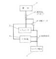
図1は本発明の実施の形態におけるバックアップ充電回路の構成を示すブロック図である。ここで、前記従来例を示す図2において説明した構成部材に対応し実質的に同等の機能を有するものには同一の符号を付してこれを示す。図1において、1は電池、2は逆流防止ダイオード、3はレギュレータ回路、4は制限抵抗体、5はバックアップ電池、6は充電スイッチ、および7は比較器である。
【0013】
以下、図1を参照しながら実施の形態のバックアップ充電回路について動作を説明する。
【0014】
電池1が逆流防止ダイオード2を介した電圧がバックアップ電池5の耐圧を考慮された設定出力電圧(例えば3.0V)をもつレギュレータ回路3を動作出来る範囲であれば、バックアップ電池5は3.0Vに充電される。その時の充電スイッチ6は非動作である。
【0015】
電池1の電圧が低下した場合、逆流防止ダイオード2を介したレギュレータ回路3の電源も低下するので、設定した電圧を出力出来なくなるまでダイナミックレンジが狭まったポイントで、レギュレータ出力電圧が低下する。レギュレータ出力電圧がバックアップ電池5の電圧以上であれば、レギュレータ回路3からのバックアップ充電は行われるが、レギュレータ出力電圧がバックアップ電池5の電圧を下まわった時にレギュレータ回路3からのバックアップ充電は不可能となる。
【0016】
そこで、レギュレータ回路3の出力電圧とバックアップ電池5の電圧を比較器7で比較することにより、レギュレータ出力電圧がバックアップ電池5の電圧を下まわった時には充電スイッチ6を動作させることによって、電池1から逆流防止ダイオード2を介した電圧で充電を継続することにより、電池1の電圧低下に対し極限までバックアップ電池5への充電を可能とする(特性図は図3を参照)。例えば、バックアップ電池5の電圧が2.0Vだった場合、逆流防止ダイオード2のVTが0.3Vだったとすれば、電池1の電圧は1.7V(2.0V−0.3V)までへの充電が可能となる。
【0017】
尚、充電スイッチ6からの充電モードは電池1の電圧が低い区間であり、バックアップ電池5の耐圧を超過することはない。
【0018】
【発明の効果】
以上説明したように、本発明のバックアップ回路は、電池電源電圧が高くレギュレータ回路の出力電圧で充電するモードに加え、電池電圧低下時のために電池電源から逆流防止ダイオードを通した電圧で可能な限り充電をするモードを備えることにより、効率的な充電を実現できる。
【図面の簡単な説明】
【図1】本発明の実施の形態におけるバックアップ充電回路の構成を示すブロック図
【図2】従来のバックアップ充電回路の構成を示すブロック図
【図3】本発明の実施の形態におけるバックアップ充電特性を示す図
【図4】従来のバックアップ充電特性を示す図
【符号の説明】
1 電池
2 逆流防止ダイオード
3 レギュレータ回路
4 制限抵抗体
5 バックアップ電池
6 充電スイッチ
7 比較器[0001]
BACKGROUND OF THE INVENTION
The present invention relates to a backup charging circuit that performs backup charging for a memory, a microcomputer, and a clock function using a backup battery.
[0002]
[Prior art]
In recent years, with the widespread use of portable devices, a backup battery is required to operate necessary functions in various devices having a clock function and the like even when the battery power supply is removed or when the battery voltage drops. When the battery power supply is removed or the battery voltage drops, the charging supply source to the backup battery is lost, and when the backup battery falls below a certain voltage due to the current consumption of the device powered by the backup battery, the memory or microcomputer that uses the backup battery as the power source And the clock function data are deleted. In order to reduce the possibility of erasing data, backup charging is performed as much as possible during normal operation (see Patent Document 1).
[0003]
A conventional backup charging circuit is configured as shown in FIG. In FIG. 2, 1 is a battery, 2 is a backflow prevention diode, 3 is a regulator circuit, 4 is a limiting resistor, and 5 is a backup battery.
[0004]
Hereinafter, the operation of the backup charging circuit will be described. The charging current is charged to the
[0005]
[Patent Document 1]
JP-A-11-67807 [0006]
[Problems to be solved by the invention]
Since the withstand voltage of the backup battery is lower than the battery power supply voltage, the output voltage of the regulator circuit is set to a voltage that does not exceed the withstand voltage of the backup battery. However, when the battery voltage decreases, the output voltage of the regulator circuit decreases as shown in FIG. When the output voltage of the regulator circuit becomes lower than the backup battery voltage, it cannot be charged, and the backup battery charge is consumed by the memory, microcomputer, and clock function, so the data is erased unless the backup battery is charged again. It had the problem that there is a possibility of.
[0007]
The present invention is directed to solving the problems of the prior art, and provides a backup charging circuit that realizes charging of the backup battery to the limit of battery voltage drop and minimizes the possibility of data erasure. The purpose is to do.
[0008]
[Means for Solving the Problems]
In order to achieve this object, a backup charging circuit according to the present invention is a backup charging circuitusing a power supply battery and a backup battery, and a regulator circuit for charging the backup battery using the power supply battery as a power source and a direct backup from the power supply battery. It has a switch for charging the battery and a comparator that compares the output voltage of the regulator circuit with the voltage of the backup battery, and conducts the switch when the output voltage of the regulator circuit falls below the voltage of the backup battery. Features.
[0009]
The power supply battery, a backup charging circuit using the regulator circuit to charge the backup battery as a power supply backup battery and power cell, by comparing the output voltage and the backup battery voltageLes Gyuta circuit, the backup battery when the voltage is below the regulator circuit output voltage, and charging from the regulator circuit output voltage of the backup battery is when the above regulator circuit output voltage,characterized by charging directly from the battery power source.
[0010]
By adopting the above-described configuration, the backup charging circuit according to the present invention has a mode in which the battery power supply voltage is high and the battery is charged with the output voltage of the regulator circuit, and in addition, a mode in which the battery power is charged as much as possible with the voltage passing through the backflow prevention diode. By providing, efficient charging can be realized.
[0011]
DETAILED DESCRIPTION OF THE INVENTION
Hereinafter, embodiments of the present invention will be described in detail with reference to the drawings.
[0012]
FIG. 1 is a block diagram showing a configuration of a backup charging circuit according to an embodiment of the present invention. Here, components corresponding to the components described in FIG. 2 showing the conventional example and having substantially the same functions are denoted by the same reference numerals. In FIG. 1, 1 is a battery, 2 is a backflow prevention diode, 3 is a regulator circuit, 4 is a limiting resistor, 5 is a backup battery, 6 is a charge switch, and 7 is a comparator.
[0013]
The operation of the backup charging circuit according to the embodiment will be described below with reference to FIG.
[0014]
If the voltage of the
[0015]
When the voltage of the
[0016]
Therefore, by comparing the output voltage of the
[0017]
Note that the charging mode from the charging switch 6 is a section where the voltage of the
[0018]
【The invention's effect】
As described above, the backup circuit according to the present invention can be operated by a voltage passing through a backflow prevention diode from the battery power supply when the battery voltage drops in addition to the mode in which the battery power supply voltage is high and charging is performed by the output voltage of the regulator circuit. Efficient charging can be realized by providing a mode for charging as much as possible.
[Brief description of the drawings]
FIG. 1 is a block diagram showing a configuration of a backup charging circuit in an embodiment of the present invention. FIG. 2 is a block diagram showing a configuration of a conventional backup charging circuit. FIG. 3 shows backup charging characteristics in an embodiment of the present invention. Figure [Figure 4] Diagram showing conventional backup charge characteristics [Explanation of symbols]
DESCRIPTION OF
Claims (4)
Translated fromJapanese前記電源電池を電源として前記バックアップ電池を充電するレギュレータ回路と、前記電源電池から直接前記バックアップ電池を充電するスイッチと、前記レギュレータ回路の出力電圧と前記バックアップ電池の電圧とを比較して、前記レギュレータ回路の出力電圧が前記バックアップ電池の電圧を下まわったときに前記スイッチを導通動作させる比較器とを備えたバックアップ充電回路。A backup charging circuit using a power battery and a backup battery,
A regulator circuit for charging the backup battery using the power battery as a power source, a switch for charging the backup battery directly from the power battery, an output voltage of the regulator circuit and a voltage of the backup battery, and comparing the regulator A backup charging circuitcomprising: a comparator that conducts the switch when the output voltage of the circuit falls below the voltage of the backup battery.
前記レギュレータ回路の出力電圧と前記バックアップ電池の電圧とを比較して、前記バックアップ電池の電圧が前記レギュレータ回路出力電圧以下のとき、前記レギュレータ回路出力から前記バックアップ電池を充電し、前記バックアップ電池の電圧が前記レギュレータ回路出力電圧以上のとき、前記電源電池から直接充電するバックアップ充電回路。A backup charging circuit using a power supply battery, a backup battery, and a regulator circuit that charges the backup battery using the power supply battery as a power source,
Comparing the output voltage of the regulator circuit and the voltage of the backup battery, and when the voltage of the backup battery is less than or equal to the regulator circuit output voltage, the backup battery is charged from the regulator circuit output, and the voltage of the backup battery A backup charging circuit thatdirectly charges from the power supply battery when is equal to or higher than the regulator circuit output voltage .
Priority Applications (3)
| Application Number | Priority Date | Filing Date | Title |
|---|---|---|---|
| JP2002304775AJP3873864B2 (en) | 2002-10-18 | 2002-10-18 | Backup charging circuit |
| US10/685,700US6979915B2 (en) | 2002-10-18 | 2003-10-16 | Portable equipment with backup battery charging function |
| US11/232,869US7105951B2 (en) | 2002-10-18 | 2005-09-23 | Backup battery charging circuit |
Applications Claiming Priority (1)
| Application Number | Priority Date | Filing Date | Title |
|---|---|---|---|
| JP2002304775AJP3873864B2 (en) | 2002-10-18 | 2002-10-18 | Backup charging circuit |
Publications (2)
| Publication Number | Publication Date |
|---|---|
| JP2004140953A JP2004140953A (en) | 2004-05-13 |
| JP3873864B2true JP3873864B2 (en) | 2007-01-31 |
Family
ID=32452099
Family Applications (1)
| Application Number | Title | Priority Date | Filing Date |
|---|---|---|---|
| JP2002304775AExpired - Fee RelatedJP3873864B2 (en) | 2002-10-18 | 2002-10-18 | Backup charging circuit |
Country Status (2)
| Country | Link |
|---|---|
| US (2) | US6979915B2 (en) |
| JP (1) | JP3873864B2 (en) |
Families Citing this family (7)
| Publication number | Priority date | Publication date | Assignee | Title |
|---|---|---|---|---|
| JP3873864B2 (en)* | 2002-10-18 | 2007-01-31 | 松下電器産業株式会社 | Backup charging circuit |
| JP4805223B2 (en)* | 2007-07-27 | 2011-11-02 | レノボ・シンガポール・プライベート・リミテッド | Charging system and charging method |
| KR101843983B1 (en)* | 2011-06-14 | 2018-03-30 | 삼성전자주식회사 | Apparatus and method for changing a battery in a portable terminal |
| TWI448886B (en)* | 2011-07-28 | 2014-08-11 | Quanta Comp Inc | Rack server system and control method thereof |
| US9236752B2 (en) | 2012-09-07 | 2016-01-12 | Qualcomm Incorporated | Method and system for voltage collapse protection |
| KR101692314B1 (en)* | 2015-03-27 | 2017-01-03 | 주식회사 주빅 | Dissolution system of lipophilic drugs into biodegradable polymer: Smart Polymer System |
| CN114362326B (en)* | 2022-01-28 | 2024-07-16 | 北京小米移动软件有限公司 | Charging and discharging system, method and device, terminal equipment and storage medium |
Family Cites Families (8)
| Publication number | Priority date | Publication date | Assignee | Title |
|---|---|---|---|---|
| BR7600097A (en)* | 1975-01-21 | 1976-08-31 | Lucas Industries Ltd | ELECTRIC SYSTEM FOR BATTERY-POWERED VEHICLE |
| JP2699865B2 (en) | 1994-03-31 | 1998-01-19 | 日本電気株式会社 | Power supply system for in-vehicle portable wireless telephone |
| US5666041A (en)* | 1996-08-27 | 1997-09-09 | The University Of Toledo | Battery equalization circuit with ramp converter |
| JP3210278B2 (en)* | 1996-10-02 | 2001-09-17 | キヤノン株式会社 | Charging device and charging method |
| JPH10215737A (en)* | 1997-02-03 | 1998-08-18 | Ryobi Ltd | Power reel for fishing |
| JP2001025161A (en)* | 1999-07-06 | 2001-01-26 | Sanyo Electric Co Ltd | Power supply circuit |
| JP3560512B2 (en) | 1999-08-06 | 2004-09-02 | 株式会社リコー | Power supply circuit and constant voltage circuit used therefor |
| JP3873864B2 (en)* | 2002-10-18 | 2007-01-31 | 松下電器産業株式会社 | Backup charging circuit |
- 2002
- 2002-10-18JPJP2002304775Apatent/JP3873864B2/ennot_activeExpired - Fee Related
- 2003
- 2003-10-16USUS10/685,700patent/US6979915B2/ennot_activeExpired - Lifetime
- 2005
- 2005-09-23USUS11/232,869patent/US7105951B2/ennot_activeExpired - Lifetime
Also Published As
| Publication number | Publication date |
|---|---|
| JP2004140953A (en) | 2004-05-13 |
| US20050068006A1 (en) | 2005-03-31 |
| US7105951B2 (en) | 2006-09-12 |
| US6979915B2 (en) | 2005-12-27 |
| US20060028079A1 (en) | 2006-02-09 |
Similar Documents
| Publication | Publication Date | Title |
|---|---|---|
| US6384570B2 (en) | Battery pack and charge circuit therefor | |
| US7550948B2 (en) | Modulation charging circuitry for battery charging using a power source providing different levels of current | |
| US5177371A (en) | Auxiliary battery operation detection circuit | |
| JP6203983B1 (en) | Dynamic sleep mode based on battery charge | |
| CN101667739B (en) | Power supply device and discharging method thereof | |
| JP3873864B2 (en) | Backup charging circuit | |
| US6199168B1 (en) | Personal computer card power management system | |
| DE60209373D1 (en) | FLASH DEVICE WITH IM-POWER SUPPLY OR ON-CHIP POWER SUPPLY | |
| JPS59204429A (en) | Power source control circuit | |
| JP4499932B2 (en) | Portable electronic devices | |
| JP2012173063A (en) | Composite device system | |
| US6427210B2 (en) | Apparatus and method for power management of embedded subsystems | |
| EP1057652A3 (en) | Printer and charging device | |
| JP2019103305A (en) | Power supply device and communication device | |
| JP3492150B2 (en) | Battery-powered equipment | |
| JP2003339125A (en) | Backup power supply control circuit | |
| CN100362450C (en) | Protection circuit | |
| KR200238177Y1 (en) | Apparatus for enhancing efficiency and prolonging life-cycle of camcorder battery | |
| JPH10312228A (en) | Backup circuit | |
| JP4449860B2 (en) | Power supply switch device and electronic device using the same | |
| JPH01128111A (en) | Power supply system | |
| KR100609763B1 (en) | Laser pointer | |
| KR950002106Y1 (en) | Battery trickle / quick charge control circuit | |
| JP3026696B2 (en) | Charge control circuit | |
| KR19990018618A (en) | Extended Battery Pack for Notebook Computers |
Legal Events
| Date | Code | Title | Description |
|---|---|---|---|
| A621 | Written request for application examination | Free format text:JAPANESE INTERMEDIATE CODE: A621 Effective date:20050309 | |
| RD01 | Notification of change of attorney | Free format text:JAPANESE INTERMEDIATE CODE: A7421 Effective date:20050707 | |
| A131 | Notification of reasons for refusal | Free format text:JAPANESE INTERMEDIATE CODE: A131 Effective date:20060711 | |
| A521 | Request for written amendment filed | Free format text:JAPANESE INTERMEDIATE CODE: A523 Effective date:20060907 | |
| TRDD | Decision of grant or rejection written | ||
| A01 | Written decision to grant a patent or to grant a registration (utility model) | Free format text:JAPANESE INTERMEDIATE CODE: A01 Effective date:20061003 | |
| A61 | First payment of annual fees (during grant procedure) | Free format text:JAPANESE INTERMEDIATE CODE: A61 Effective date:20061016 | |
| R151 | Written notification of patent or utility model registration | Ref document number:3873864 Country of ref document:JP Free format text:JAPANESE INTERMEDIATE CODE: R151 | |
| FPAY | Renewal fee payment (event date is renewal date of database) | Free format text:PAYMENT UNTIL: 20091102 Year of fee payment:3 | |
| FPAY | Renewal fee payment (event date is renewal date of database) | Free format text:PAYMENT UNTIL: 20101102 Year of fee payment:4 | |
| FPAY | Renewal fee payment (event date is renewal date of database) | Free format text:PAYMENT UNTIL: 20111102 Year of fee payment:5 | |
| FPAY | Renewal fee payment (event date is renewal date of database) | Free format text:PAYMENT UNTIL: 20121102 Year of fee payment:6 | |
| FPAY | Renewal fee payment (event date is renewal date of database) | Free format text:PAYMENT UNTIL: 20121102 Year of fee payment:6 | |
| FPAY | Renewal fee payment (event date is renewal date of database) | Free format text:PAYMENT UNTIL: 20131102 Year of fee payment:7 | |
| S533 | Written request for registration of change of name | Free format text:JAPANESE INTERMEDIATE CODE: R313533 | |
| R350 | Written notification of registration of transfer | Free format text:JAPANESE INTERMEDIATE CODE: R350 | |
| S111 | Request for change of ownership or part of ownership | Free format text:JAPANESE INTERMEDIATE CODE: R313113 | |
| R350 | Written notification of registration of transfer | Free format text:JAPANESE INTERMEDIATE CODE: R350 | |
| R250 | Receipt of annual fees | Free format text:JAPANESE INTERMEDIATE CODE: R250 | |
| LAPS | Cancellation because of no payment of annual fees |