JP3872776B2 - Semiconductor manufacturing apparatus and semiconductor manufacturing method - Google Patents
Semiconductor manufacturing apparatus and semiconductor manufacturing methodDownload PDFInfo
- Publication number
- JP3872776B2 JP3872776B2JP2003197936AJP2003197936AJP3872776B2JP 3872776 B2JP3872776 B2JP 3872776B2JP 2003197936 AJP2003197936 AJP 2003197936AJP 2003197936 AJP2003197936 AJP 2003197936AJP 3872776 B2JP3872776 B2JP 3872776B2
- Authority
- JP
- Japan
- Prior art keywords
- flow rate
- mass flow
- flow controller
- unit
- output
- Prior art date
- Legal status (The legal status is an assumption and is not a legal conclusion. Google has not performed a legal analysis and makes no representation as to the accuracy of the status listed.)
- Expired - Fee Related
Links
- 238000004519manufacturing processMethods0.000titleclaimsdescription28
- 239000004065semiconductorSubstances0.000titleclaimsdescription27
- 238000001514detection methodMethods0.000claimsdescription27
- 239000012530fluidSubstances0.000claimsdescription24
- 238000012545processingMethods0.000claimsdescription22
- 238000000034methodMethods0.000claimsdescription21
- 238000012937correctionMethods0.000claimsdescription14
- 238000003860storageMethods0.000claimsdescription14
- 238000011144upstream manufacturingMethods0.000claimsdescription13
- 239000000758substrateSubstances0.000claimsdescription12
- 239000007789gasSubstances0.000description51
- 238000010438heat treatmentMethods0.000description19
- 239000007788liquidSubstances0.000description15
- 238000006243chemical reactionMethods0.000description14
- 238000010586diagramMethods0.000description9
- 235000012431wafersNutrition0.000description8
- 238000010926purgeMethods0.000description7
- 239000011248coating agentSubstances0.000description3
- 238000000576coating methodMethods0.000description3
- 238000005259measurementMethods0.000description3
- 230000007613environmental effectEffects0.000description2
- 238000005530etchingMethods0.000description2
- 238000012423maintenanceMethods0.000description2
- 230000001590oxidative effectEffects0.000description2
- IJGRMHOSHXDMSA-UHFFFAOYSA-NAtomic nitrogenChemical compoundN#NIJGRMHOSHXDMSA-UHFFFAOYSA-N0.000description1
- 230000002159abnormal effectEffects0.000description1
- 230000003321amplificationEffects0.000description1
- 230000007797corrosionEffects0.000description1
- 238000005260corrosionMethods0.000description1
- 230000007423decreaseEffects0.000description1
- 230000006866deteriorationEffects0.000description1
- 229910001873dinitrogenInorganic materials0.000description1
- 230000000694effectsEffects0.000description1
- 239000011261inert gasSubstances0.000description1
- 238000007689inspectionMethods0.000description1
- 230000010354integrationEffects0.000description1
- 239000004973liquid crystal related substanceSubstances0.000description1
- 230000007257malfunctionEffects0.000description1
- 239000000463materialSubstances0.000description1
- 238000012544monitoring processMethods0.000description1
- 238000003199nucleic acid amplification methodMethods0.000description1
- 230000000737periodic effectEffects0.000description1
- 239000002243precursorSubstances0.000description1
- 239000000126substanceSubstances0.000description1
- 239000002341toxic gasSubstances0.000description1
- 239000006200vaporizerSubstances0.000description1
Images


Classifications
- H—ELECTRICITY
- H01—ELECTRIC ELEMENTS
- H01L—SEMICONDUCTOR DEVICES NOT COVERED BY CLASS H10
- H01L21/00—Processes or apparatus adapted for the manufacture or treatment of semiconductor or solid state devices or of parts thereof
- H01L21/67—Apparatus specially adapted for handling semiconductor or electric solid state devices during manufacture or treatment thereof; Apparatus specially adapted for handling wafers during manufacture or treatment of semiconductor or electric solid state devices or components ; Apparatus not specifically provided for elsewhere
- H01L21/67005—Apparatus not specifically provided for elsewhere
- H01L21/67011—Apparatus for manufacture or treatment
- H01L21/67017—Apparatus for fluid treatment
- G—PHYSICS
- G05—CONTROLLING; REGULATING
- G05D—SYSTEMS FOR CONTROLLING OR REGULATING NON-ELECTRIC VARIABLES
- G05D7/00—Control of flow
- G05D7/06—Control of flow characterised by the use of electric means
- G05D7/0617—Control of flow characterised by the use of electric means specially adapted for fluid materials
- G05D7/0629—Control of flow characterised by the use of electric means specially adapted for fluid materials characterised by the type of regulator means
- G05D7/0635—Control of flow characterised by the use of electric means specially adapted for fluid materials characterised by the type of regulator means by action on throttling means
- G—PHYSICS
- G01—MEASURING; TESTING
- G01F—MEASURING VOLUME, VOLUME FLOW, MASS FLOW OR LIQUID LEVEL; METERING BY VOLUME
- G01F1/00—Measuring the volume flow or mass flow of fluid or fluent solid material wherein the fluid passes through a meter in a continuous flow
- G01F1/68—Measuring the volume flow or mass flow of fluid or fluent solid material wherein the fluid passes through a meter in a continuous flow by using thermal effects
- G—PHYSICS
- G01—MEASURING; TESTING
- G01F—MEASURING VOLUME, VOLUME FLOW, MASS FLOW OR LIQUID LEVEL; METERING BY VOLUME
- G01F15/00—Details of, or accessories for, apparatus of groups G01F1/00 - G01F13/00 insofar as such details or appliances are not adapted to particular types of such apparatus
- G01F15/02—Compensating or correcting for variations in pressure, density or temperature
- G01F15/022—Compensating or correcting for variations in pressure, density or temperature using electrical means
- G01F15/024—Compensating or correcting for variations in pressure, density or temperature using electrical means involving digital counting
- G—PHYSICS
- G01—MEASURING; TESTING
- G01F—MEASURING VOLUME, VOLUME FLOW, MASS FLOW OR LIQUID LEVEL; METERING BY VOLUME
- G01F25/00—Testing or calibration of apparatus for measuring volume, volume flow or liquid level or for metering by volume
- G01F25/10—Testing or calibration of apparatus for measuring volume, volume flow or liquid level or for metering by volume of flowmeters
- H—ELECTRICITY
- H01—ELECTRIC ELEMENTS
- H01L—SEMICONDUCTOR DEVICES NOT COVERED BY CLASS H10
- H01L21/00—Processes or apparatus adapted for the manufacture or treatment of semiconductor or solid state devices or of parts thereof
- H01L21/67—Apparatus specially adapted for handling semiconductor or electric solid state devices during manufacture or treatment thereof; Apparatus specially adapted for handling wafers during manufacture or treatment of semiconductor or electric solid state devices or components ; Apparatus not specifically provided for elsewhere
- H01L21/67005—Apparatus not specifically provided for elsewhere
- H01L21/67242—Apparatus for monitoring, sorting or marking
- H01L21/67253—Process monitoring, e.g. flow or thickness monitoring
Landscapes
- Physics & Mathematics (AREA)
- General Physics & Mathematics (AREA)
- Fluid Mechanics (AREA)
- Engineering & Computer Science (AREA)
- Automation & Control Theory (AREA)
- Manufacturing & Machinery (AREA)
- Condensed Matter Physics & Semiconductors (AREA)
- Computer Hardware Design (AREA)
- Microelectronics & Electronic Packaging (AREA)
- Power Engineering (AREA)
- Flow Control (AREA)
- Measuring Volume Flow (AREA)
- Chemical Vapour Deposition (AREA)
- Semiconductor Integrated Circuits (AREA)
Description
Translated fromJapanese【0001】
【発明の属する技術分野】
マスフローコントローラにより流量が調整された流体により基板例えば半導体ウエハに対して処理を行う半導体製造装置に関する。
【0002】
【従来の技術】
従来、半導体製造工程においては、所定のガスや液体により基板に対して処理を行う工程がある。ガスを用いた工程としては、成膜ガスを用いた成膜工程、酸化ガスを用いた酸化工程、エッチングガスを用いたエッチング工程などがあり、また液体を用いた工程としては、基板上にレジスト液を供給する工程、絶縁膜の前駆物質を含む薬液を塗布する工程などが挙げられる。
【0003】
一方、最近において、半導体デバイスのパターンが微細化され、各膜の膜厚も薄くなってきていることから、ガスや液体などの供給流量を高い精度でコントロールする必要があり、そのための機器として、マスフローコントローラが用いられている。
【0004】
マスフローコントローラは、細管内に流れる液体が発熱抵抗線から熱を奪い、発熱抵抗線の抵抗値が変わることを検出原理とし、流量検出部と、流量検出部から出力される出力電圧(流量に対応する検出電圧)と、設定流量に応じた設定電圧とを比較する比較部と、この比較部からの比較出力により操作される流量調整バルブとを備えている。
【0005】
しかしながら、マスフローコントローラにおいて、使用しているうちに実流量が設定流量から外れてくることがある。例えば実流量が0の場合であっても、検出部から出力される電圧値は0ではなく、わずかにずれて誤差が生じることが多い。この要因としては、メーカー出荷時の環境温度とユーザ側の環境温度により誤差が生じること、ブリッジ回路の要素であるコイル状の発熱抵抗線(センサ)のコーティング材の経時劣化や剥離、発熱抵抗線のコイルの緩み、回路部分の不具合、電源電圧の変動、センサが巻かれている管路の汚れ(腐食や生成物付着など)、といったことが挙げられる。マスフローコントローラにおいて設定可能な流量のうち、流体の流量が多い場合の流量誤差割合と、流量が少ない場合の流量誤差割合では、同じドリフト量である場合、流量が少ない場合の方が誤差の影響は大きくなり、例えば半導体ウエハ表面に生成される膜厚に与える影響も大きくなる。
【0006】
近年、半導体デバイスの高集積化、薄膜化に伴い、製造時の半導体ウエハ表面における膜厚の許容範囲は厳しくなる状況にある。そこで膜厚を許容範囲内に保って製造を行うために、マスフローコントローラにおいて設定可能な流量のうち、最大流量付近で使用することにより、流量誤差の程度を小さく抑えられるようにすることも行われている。例えば、複数の工程を行う場合において、各工程の間で流体の設定流量に大きな差がある場合、流量容量の大きいマスフローコントローラと、流量容量の小さいマスフローコントローラを2基以上並列接続して、流体の設定流量に応じてマスフローコントローラを切り替えることも行われているが、複数のマスフローコントローラを用意しなければならないことや、また出力がドリフトしたとき、即ち流体流量が0のときの出力電圧が0でない場合には、そのドリフト分が処理に影響を与えるおそれもあり、例えば次世代あるいは次次世代のデバイスにおいてはその影響が懸念されている。
【0007】
更にまた実流量が設定流量から外れてくる現象として、ゼロ点シフトの他に流量に対する出力電圧の変化割合(傾き)即ちスパンが変動することが挙げられる。このスパンシフトは、ブリッジ回路に含まれるセンサである上流側の発熱抵抗線と下流側の発熱抵抗線について、流量変化に対する温度変化量つまり出力電圧の変化量が初期校正時から変わってくることが要因の一つである。
【0008】
一方、特許文献1には、マスフローコントローラとは別個に測定器をガス流路に介設し、この測定器の測定結果に基づいて校正器によりマスフローコントローラを調整することが記載されている。また特許文献2には、予めメーカー側で初期校正時にガスを流さない状態でマスフローコントローラのセンサコイルに通じる電流値を段階的に変化させ、両コイルに通じる電流差から生じる温度差をブリッジ回路の不平衡電圧として取り出し、この不平衡電圧と使用中の不平衡電圧とを比較してゼロ点補正量及びスパン補正量とを求めることが記載されている。
【0009】
【特許文献1】
特開平7−263350号公報 段落0014及び図1
【特許文献2】
特開平5−289751号公報 第9欄第3行〜第9行
【0010】
【発明が解決しようとする課題】
特許文献1のように、測定器を用いる手法は、別途測定器を用意しなければならないし、測定器自体に不具合が生じた場合には対応できない。また校正器を用いて行う校正は、現実には手動で可変抵抗値をオペレータが調整することになると思われるが、頻繁に調整しようとすると、作業が煩わしいという問題がある。また、特許文献2のように、不平衡電圧を介して調整する手法については、マスフローコントローラは、種々のメーカーから発売されており、ある特定のメーカーのマスフローコントローラを適用して生産ラインを構成した場合、マスフローコントローラを他社のものに交換した場合には、その調整を行うことができない欠点がある。また電流値を段階的に変えてブリッジ回路に供給する機構が必要となり、装置構成が繁雑であるという不利益もある。
【0011】
本発明は上記した問題点に鑑みなされるもので、マスフローコントローラを配管から取り外すことなく高精度に流量を設定できる半導体製造装置及び半導体製造方法を提供することを目的とする。
【0012】
【課題を解決するための手段】
本発明に係る半導体製造装置は、流体が供給されて基板に対して半導体集積回路装置を製造するための処理が行われる処理部と、
この処理部に流体を供給する流体供給路と、
この流体供給路に設けられ、流体の流量を検出する検出部と、設定流量に対応する設定電圧と前記検出部の出力電圧とを比較して操作信号を出力する比較部と、この比較部からの操作信号に基づいて流体の流量を調整する流量調整部と、を備えるマスフローコントローラと、
このマスフローコントローラの上流側及び下流側に夫々設けられた第1及び第2の遮断弁と、
設定流量に対応する設定電圧を出力する設定電圧出力部と、
これら第1及び第2の遮断弁を閉じたときにマスフローコントローラの検出部から出力される出力電圧を記憶する記憶部と、
前記設定電圧出力部から出力される設定電圧に前記記憶部に記憶された出力電圧を加算して、流量ゼロ時にマスフローコントローラの検出部から出力される出力電圧の大きさだけ設定電圧を補正し、補正された値を設定電圧としてマスフローコントローラに出力する設定電圧補正部と、を備えることを特徴とする。
【0013】
この発明によれば、流量ゼロ時の出力電圧の変化を補償するにあたって、マスフローコントローラを調整するのではなく設定流量に対応する設定電圧を補正しているため、簡単にマスフローコントローラの微調整を行うことができる。この発明においては、第1及び第2の遮断弁を閉じて出力電圧の値を記憶部に取り込むタイミングを設定するためのタイミング設定手段を備える構成としてもよいし、また前記出力電圧の変化分が、予め定めた閾値から外れた場合に警報を発する警報発生手段を備える構成としてもよい。
【0018】
なお本発明は、マスフローコントローラには液体が流れるが、その後液体がガス化されてそのガスにより基板に対して処理が行われる場合も含まれる。
【0019】
本発明は方法としても成立するものであり、本発明に係る半導体製造方法は、流体の流量を検出する検出部と、設定流量に対応する設定電圧と前記検出部の出力電圧とを比較して操作信号を出力する比較部と、この比較部からの操作信号に基づいて流体の流量を調整する流量調整部と、を備えるマスフローコントローラを用いて処理部に流体を供給し、この処理部にて半導体集積回路装置を製造するための処理を行う半導体製造方法において、
このマスフローコントローラの上流側及び下流側に夫々設けられた第1及び第2の遮断弁を閉じる工程と、
これら第1及び第2の遮断弁を閉じたときにマスフローコントローラの検出部から出力される出力電圧を記憶する工程と、
設定電圧出力部から設定流量に対応する設定電圧を出力する工程と、
前記設定電圧出力部から出力される設定電圧に前記記憶部に記憶された出力電圧を加算して、流量ゼロ時にマスフローコントローラの検出部から出力される出力電圧の大きさだけ設定電圧を補正し、補正された値を設定電圧としてマスフローコントローラに出力する工程と、を備えることを特徴とする。
【0022】
【発明の実施の形態】
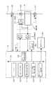
以下、本発明における実施の形態を図面に基づき説明する。まず、図1には、本発明の実施の形態における半導体製造装置(以下製造装置と称する)の主な構成を示すブロック図が示されている。1は、基板に対して半導体集積回路を製造するための処理が行われる処理部例えば熱処理部である。この熱処理部1は、この例では反応容器(処理容器)である縦型の反応チューブ11内に、基板であるウエハWを多数枚搭載した保持具12を搬入して、反応チューブ11の外側に設けられた図示しない加熱手段により加熱するとともに、例えばガス供給管からなるガス供給路2から反応チューブ11内に所定のガスを導入して、基板に対して所定の熱処理が行われる。13は排気管、14は真空排気手段である真空ポンプ、15はガス供給路2と排気管13との間を反応チューブ11を迂回して接続するバイパス路、21、22、23は各々バルブ例えば遮断弁である。
【0023】
前記ガス供給路2には、ガス供給源40よりのガス流量を調整するためのマスフローコントローラ3が設けられており、このマスフローコントローラ3の上流側及び下流側には夫々遮断弁41、42が設けられている。遮断弁41、42の双方を閉じることで、マスフローコントローラ3における流体、この例ではガスの流れを遮断することができる、即ちガス流量を0とすることができるようになっている。
【0024】
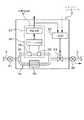
マスフローコントローラ3は、図2に示すように流量検出部31、比較部(調節部)32及び流量調整部であるコントロールバルブ(流量調整バルブ)33を備えている。マスフローコントローラ3の詳しい構成について図3に基づき説明すると、マスフローコントローラ3の内部に導入される前記ガス供給管2は一度本流部3aと側流部3bとに分流する。側流部3bには、ガス供給管2内における流量を計測する2つの発熱抵抗線34、35からなる流量センサが設けられ、本流部3aには、側流路3bと本流路3aとの流量等の各種条件を同等なものにするバイパス部30が設けられている。前記バイパス部30は、本流路3aにおける流量、温度、圧力などを側流路3bと同様の特性となるように設けられているものであり、これによりセンサ34、35における測定誤差を防止することができる。流量の検出原理については、上流側センサ34では流体が流れると熱が奪われて温度が下降し、逆に下流側センサ35では熱が与えられ温度が上昇する。この結果上流側センサ34と下流側センサ35とでは温度差が生じ、この温度差を検出するようになっている。
【0025】
マスフローコントローラ3には、他に前記発熱抵抗線34、35の抵抗値の差を電圧信号として検出するブリッジ回路36と、その電圧信号を増幅する増幅回路37とを備え、発熱抵抗線34、35、ブリッジ回路36及び増幅回路37は、前記流量検出部31を構成するものである。前記比較部32は、後述の設定流量に対応する設定信号(設定電圧)と増幅回路37からの電圧とを比較し、その比較結果(偏差)に応じてコントロールバルブ33の開度を調整するための操作信号を出力するものである。
【0026】
またマスフローコントローラ3には、信号変換部5を介して制御部6が接続されている。信号変換部5は、マスフローコントローラ3からのアナログ信号をディジタル信号に、また制御部6からのディジタル信号をアナログ信号に夫々変換するためのものである。
【0027】
また制御部6には、例えば液晶パネルなどからなる表示部51が接続されており、この表示部51は、タッチパネル式の入力装置も兼ねている。次いで、制御部6の詳しい構成について図2に基づいて説明すると、6aはデータバス、60は装置の制御を実施するCPUである。61はマスフローコントローラ3の設定流量に対応する設定電圧を出力する設定電圧出力部であり、例えば0〜5Vの設定電圧によりマスフローコントローラ3の流量を0%〜100%に設定できるようになっている。62は第1の記憶部であり、遮断弁41、42を閉じたときにおいてマスフローコントローラ3から出力される出力電圧(流量検出部31からの電圧検出値)がドリフト電圧として記憶される。63は第1の設定電圧補正部であり、遮断弁41、42を閉じたときにおいてマスフローコントローラ3から出力される出力電圧が基準電圧(この例では0V)と異なる場合、つまりドリフト電圧である±E0(V)が発生しているときに設定電圧を補正するものである。64は第1のタイミング設定部であり、遮断弁41、42を閉じてマスフローコントローラ3に対する設定電圧を見直す(補正する)タイミングを設定するものである。65は、アラーム用比較回路部であり、前記ドリフト電圧が予め設定された閾値を越えているか否か判断し、閾値を越えていればアラーム発生部66に警告(例えば警告音や警告表示)を発生させる。なお、本実施の形態では、基準値となる電圧値よりも、0.3V(300mV)を閾値とし、この閾値以上離れた値がマスフローコントローラ3から計測された場合にはマスフローコントローラ3の不具合が考えられるため、例えばアラーム発生部66からの警報出力と、操作パネル51への警報表示により作業者に対して通報するようになっている。
【0028】
次に上述の実施の形態の作用について図4のフローチャートと、図5のグラフに基づき説明する。本実施の形態において使用されるマスフローコントローラ3は、流量と出力電圧がリニアであって、最大流量が500cc/分であり、その際の出力電圧が5Vとなるように設計されているものとして説明する。
【0029】
先ずマスフローコントローラ3が装置に組み込まれたときには、流量ゼロの状態で出力電圧がゼロに設定されており、この状態で熱処理部1において基板例えばウエハWに対して所定の熱処理が行われる。即ち実行すべきプロセスの設定流量に対応する設定電圧が制御部6から信号処理部5を介してマスフローコントローラ3に与えられ、マスフローコントローラ3では反応チューブ11に供給される処理ガスが設定流量となるようにコントロールバルブ33(図2参照)が調整される。例えば設定流量が400cc/分であったとすると、マスフローコントローラ3には4Vの電圧が与えられる。マスフローコントローラ3に対して初期校正が行われた直後であれば、流量ゼロ時の出力電圧はゼロであるから、400cc/分の設定値通りの流量で処理ガスが反応チューブ11に供給される。
【0030】
次いでタイミング設定部64にて設定されたタイミング、熱処理が行われる前後の待機時間においてマスフローコントローラ3の状態を以下のようにして調べる。まず、前記遮断弁41、42を両方とも閉じて、マスフローコントローラ3内にガスが流入しない状況とすると共に、例えば制御部6側からの指示によりマスフローコントローラ3のコントロールバルブ33(図3参照)を「開」状態例えば全開状態としてセンサ34、35前後のガスの流れを平衡にしておく。(ステップS1)。このときのマスフローコントローラ3から出力された出力電圧(E0)すなわち流量ゼロ時のマスフローコントローラ3からの出力電圧を第1の記憶部62内に記憶する(ステップS2)。なおこの例ではE0が+0.1Vであるとして説明する。
【0031】
次いで、マスフローコントローラ3から出力された出力電圧(E0)が、予め設定されている前述した閾値以内であるかどうかを判定する(ステップS3)。例えば閾値が300mVであれば、E0がこの例では+0.1V(100mV)であるから閾値内に収まっており、ステップS4に進む。前記操作パネル51から、マスフローコントローラ3の流量が400cc/分となるように設定されているとすると、第1の設定電圧補正部63によりこの設定流量に対応する設定電圧が補正される。即ち設定電圧出力部61から出力される設定電圧4Vに、前記記憶部62に記憶されているマスフローコントローラ3から出力された出力電圧(E0)0.1Vを、加算して補正し《4V+(+0.1v)=4.1V》、補正された値(4.1V)を正しい設定電圧(電圧指示値)としてマスフローコントローラ3に与える(ステップS5)。
【0032】
ここで図5はマスフローコントローラ3の出力電圧と流量との関係を示すグラフであり、初期校正時における電圧−流量特性は実線で表され、設定ポイントはA点にある。そしてマスフローコントローラ3のゼロ点がドリフト(変化)して0.1Vのドリフト電圧(出力電圧の変化分)が発生したとすると、電圧−流量特性は点線で表され、設定ポイントはB点に移行する。従ってこの状態では流量は390cc/分になっている。そこで設定電圧を既述のように補正すると、電圧−流量特性は変わらないが、設定ポイントはB点からC点に移行するので、マスフローコントローラ3により設定される流量は設定流量通り400ccとなる。
【0033】
こうしてマスフローコントローラ3の設定電圧の調整が終了したところで遮断弁41、42を開き(ステップS6)、そして反応チューブ11内にウエハWが搬入された後、バルブ21を開いて反応チューブ11内に設定流量通りのガスを供給して前記ウエハWに対して所定の熱処理を実施する(ステップS7)。この例ではゼロ点が+側にずれた場合について説明しているが、ゼロ点が−側にずれた場合例えばE0が−0.1Vである場合には、設定電圧出力部61から出力される設定電圧4Vに、−0.1Vを加算して補正し《4V+(−0.1v)=3.9V》、補正された値(3.9V)を正しい設定電圧(電圧指示値)としてマスフローコントローラ3に与えることになる。
【0034】
なおステップS3にてマスフローコントローラ3から出力された出力電圧(E0)が閾値よりも大きいと判定された場合には、アラーム発生部66によりアラームが出力されまた、表示パネル6においてマスフローコントローラ3が異常である旨を作業者に対して通報される(ステップS8)。この場合には、作業者がマスフローコントローラ3を点検するかあるいはメーカ側に修理を依頼することになる。
【0035】
上述の実施の形態によれば、マスフローコントローラ3の上流側及び下流側に設けた遮断弁41、42を閉じてマスフローコントローラ3にガスが流れないようにし、このときのマスフローコントローラ3から出力される出力電圧に基づいて、流量ゼロ時の出力電圧の変化分(ドリフト電圧)を補償するように制御部6から出力される設定電圧を補正しているため、つまりマスフローコントローラ3を調整するのではなく制御部6側で設定信号を補正しているため、マスフローコントローラ3が設置されているメンテナンスルームに作業者が入って調整するという作業が不要になるし、製造ラインを止めることなく簡便にマスフローコントローラ3の微調整を行うことができる。
【0036】
ここでオペレータがマスフローコントローラ3のゼロ点の調整を行う場合には、装置の電源をオフにしてからマスフローコントローラ3にテスタ測定用の治具を取り付け、装置の電源を再投入した後、操作画面により設定流量ゼロの入力を行い、数分そのままの状態にしてからテスターでゼロ電圧を測定し、その電圧を所定電圧の範囲内の値に調整する。しかる後装置電源をオフにして前記治具を外した後、装置電源を再投入して操作画面でアクチャルを確認する。従って上述の実施の形態によれば、装置を止めて面倒な調整作業を省くことができ、装置の運用の効率化を図ることができる。また半導体製造装置に用いるガスの中には毒性のあるガスが含まれている場合が多いので、ガス供給機器を収納しているガスボックスを開くことによる人的な危険性を回避することができる。更にまた装置のダウンタイムに影響するマスフローコントローラ3の定期点検なども省力化できる。
【0037】
上述の例では、校正されたマスフローコントローラ3にガスが流れていないときには、マスフローコントローラ3から出力される電圧がゼロであり、その電圧がゼロでないときにドリフト電圧として取り扱っている。しかしながら校正されたマスフローコントローラ3において流量ゼロ時の出力電圧がゼロでない基準電圧例えば0、1Vを発生し、かつコンピュータ側で流量500cc/分に相当する設定電圧が5.1Vとして取り扱っているシステムであっても本発明の範囲に含まれる。この場合設定電圧補正部は、マスフローコントローラ3からの出力電圧から基準電圧(例えば0.1V)を差し引き、その電圧差だけマスフローコントローラ3がドリフトしているものと取り扱って設定電圧をその電圧差で補正することとなる。
【0038】
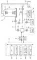
次いで、本発明の他の実施の形態を図6に基づき説明する。この例では、バイパス路15に圧力検出部71が設けられ、更にこの圧力検出部71からの圧力検出値における所定時間帯の上昇率に基づいてガス供給路2を流れる流量を求める流量基準計72が設けられている。また処理ガスを節約するために例えばマスフローコントローラ3とその上流側の遮断弁41との間にパージガス例えば窒素ガスなどの不活性ガスを供給できるように分岐路43及びバルブ例えば遮断弁44を介してパージガス供給源45が接続されている。ここで圧力上昇率とは、遮断弁44、21を閉じて遮断弁44の下流側のガス供給路2及びバイパス路15を真空排気し、その後バイパス路15の遮断弁23を閉じた後、遮断弁44を開いてマスフローコントローラ3を通じて所定の流量でガスを流し、このときの圧力上昇率を指している。なおこの実施の形態では、遮断弁41は閉じているものとする。
【0039】
流量基準計72内には圧力上昇率演算手段72aが設けられており、検知した圧力値の時系列データを図示しないワークメモリに書き込み、そのデータから圧力上昇率を演算してその値を制御部6に送るように構成されている。
【0040】
また制御部6は、圧力上昇率を記憶する第2の記憶部67、マスフローコントローラ3の校正時における圧力上昇率(初期値)とマスフローコントローラ3を使用した後に測定した圧力上昇率とに基づいてマスフローコントローラ3の設定電圧を補正する第2の設定電圧補正部68と、マスフローコントローラ3の状態をチェックするタイミングつまり校正時以外において圧力上昇率の計測を行うタイミングを設定する第2のタイミング設定部69とを備えている。制御部6は、図1に示した構成を備えており、既述のようにしてゼロ点のドリフトの調整を行うことができるが、図6では便宜上スパンのずれを補償するための部位についてのみ図示してある。
【0041】
なお図示していないが、ガス供給路2及びバイパス路15の温度を検出する温度検出部が設けられており、圧力上昇率を求めるときにその温度を考慮して、温度変化による影響をなくすようにしている。
【0042】
次に上記の圧力上昇率を求めてマスフローコントローラ3のスパンのずれを補償する動作について説明する。この例ではマスフローコントローラ3の最大設定流量は、500cc/分として説明する。またこの際の出力電圧は5Vとし、マスフローコントローラ3の検出流量と出力電圧とは比例の関係にあり、説明を簡単にするためにゼロ点のドリフトはないものとする。校正した直後のマスフローコントローラ3例えば新品のマスフローコントローラ3を取り付けた後、その上流側の遮断弁44、21を閉じて遮断弁44の下流側のガス供給路2及びバイパス路15を真空ポンプ14により真空排気し、その後バイパス路15の遮断弁23を閉じる。続いてマスフローコントローラ3に対して所定の流量(例えば最大流量の80%の流量である400cc)になるように設定電圧出力部61から設定電圧を出力して流量を設定し、遮断弁44を開いてマスフローコントローラ3を通じてパージガスを流す。
【0043】
流量基準計72は、そのときの圧力検出部71による圧力検出値の所定時間帯の時系列データを記憶し、そのデータに基づいて圧力上昇率を求めて制御部6に送信する。制御部6はこの圧力上昇率を初期値(基準値)として第2の記憶部67に記憶する。図7はこのときの圧力変化を示す図であり、T0は遮断弁41を開いた時点、T3はバイパス路15の遮断弁23を開いた時点である。圧力検出値を測定する時間帯は圧力上昇が安定している時間帯を選択することが好ましく、例えばT1〜T2の時間帯とされる。
【0044】
そして制御部6内の第2のタイミング設定部69で設定された所定のタイミング例えば既述の実施の形態と同様に熱処理が終了する度毎に、既述の圧力上昇率の初期値を求めたときと同様にして、また同一の設定流量により圧力検出部71において圧力を検知し、流量基準計72により圧力上昇率を求め、制御部6の第2の記憶部67に送信する。制御部6ではこの圧力上昇率と既に求めた初期値とを比較し、その比較結果に基づいて設定電圧を補正する。
【0045】
この手法は、バイパス路15の上流側の管路の容積を利用し、当該管路内にガスを流入させたときに流入流量と圧力上昇とが対応していることに基づいており、実流量を圧力変化として直接測定しようとするものである。従って圧力上昇率が初期値に比べて例えば2.5%早くなった(大きくなった)ときには、それだけ流量が早くなったということであるから、言い換えれば400cc/分の設定流量に対応する設定電圧4Vでは流量が予定の流量よりも2.5%早くなっているということである。従って制御部6内の第2の設定電圧補正部68では、前記マスフローコントローラ3の設定流量である400cc/分に、圧力上昇率の増加分(早くなった分)である2.5%を乗じてズレ量を算出する《400cc×2.5%(0.025)=10cc》。この演算の結果、ズレ量は10ccと算出された。このズレ量(10cc)を設定流量(400cc)で除し、これにその設定流量に対応する設定電圧(4V)を乗すれば、ズレ量分ΔEの出力電圧値が求められる《10cc/400cc×4V=0.1V》。
【0046】
図8はスパンが変化した様子を示すものであり、実線(1)は校正時のスパン(流量変化に対する出力変化分)によるグラフ、点線(2)は校正時のスパンからずれたスパンに対応するグラフである。以上の演算の結果算出された出力電圧値0.1V分を、マスフローコントローラ3の設定流量400ccに対応する設定電圧4.0Vから差し引き(4V−0.1V=3.9V)、次回の設定流量が400ccとなった場合には、出力電圧値を3.9Vとすれば、最大流量に対する80%ポイントの流量ずれを補正することができる。従って流量がズレることなく設定流量通りの流量で処理ガスを反応チューブ11内に供給して基板に対して処理を行うことができる。
【0047】
なお、この例では流量ゼロ時に出力電圧値が0Vとなっているものとして説明しているが、流量ゼロ時に出力電圧値が0Vでない場合つまりゼロ点のドリフトが生じている場合には、設定流量400ccに対応する設定電圧は、先の実施の形態において説明した方法により4.0Vを補正した電圧となる。例えばゼロ点の出力電圧の変化分が+0.1Vであって、このドリフト分を補償するために先の実施の形態にて設定流量400ccに対応する設定電圧が3.9Vに補正されているとしたならば、図8の実線(1)の400ccに対応する設定電圧は3.9Vとなり、スパン変化によるズレ量分ΔEの出力電圧値は、10cc/400cc×3.9V=0.0975Vとなる。
【0048】
この実施の形態によれば、マスフローコントローラ3を調整するのではなく制御部6側で設定信号を補正しているため、マスフローコントローラ3が設置されているメンテナンスルームに作業者が入って調整するという作業が不要になるし、製造ラインを止めることなく簡便にマスフローコントローラ3の微調整を行うことができ、装置の効率化が図れるなど、先の実施の形態と同様の効果がある。
【0049】
またマスフローコントローラ3は、設定流量と出力電圧値とは比例の関係とされているが、ある一定の設定流量のみでなく、いくつかの設定流量において、例えば設定流量が150ccの時と、300ccの時と、最大流量の500ccの時、の3つのポイントにおいて前述した方法により圧力上昇率を把握して、設定流量と出力電圧との関係を確認し、各設定流量における圧力上昇率が夫々の基準値と異なる場合には、制御部6内のプログラムにより流量と出力電圧との関係を例えば点線で示す曲線となるように補正し、この曲線に基づいて設定電圧出力部61から設定流量に対応する設定電圧が出力されるようにしてもよい。
【0050】
なおこのように流量基準計72を用いる場合においても、初期時と監視時とにおける圧力上昇率の差異が一定以上になったとき、例えば圧力上昇率の差異から換算した出力電圧のずれ分が閾値以上になったときには警報を発して作業者にしらせるようにしてもよい。
【0051】
また圧力上昇率を用いて設定電圧を補正する場合、既述のようにして補正した後例えば4Vを3.9Vに補正した後、再度その設定電圧によりマスフローコントローラ3の流量を設定して同様にして圧力上昇率の基準値に対する変化分を求め、その変化分が所定値(例えば1.0%)以内に収まるまで、同様のループ(圧力上昇率を求めて設定電圧を補正する工程)を繰り返すようにしてもよい。
【0052】
以上の説明では、圧力上昇率に基づいてスパンの変化による設定電圧の補償について述べているが、圧力上昇率に代えて圧力降下率を用い、同様にしてスパンの変化による設定電圧の補償を行ってもよい。この場合には、マスフローコントローラ3の上流側の遮断弁44を開いておき、また遮断弁21を閉じかつ遮断弁42、22、23を開いておく。つまりパージガスをマスフローコントローラ3を介してバイパス路15から排気されるようにしておく。そしてマスフローコントローラ3では所定の流量に設定しておき、この状態で遮断弁44を閉じてパージガスの供給を止め、その後の圧力検出部71による圧力値の時系列データから所定時間帯の圧力降下率を求め、この値を既述の圧力上昇率と同様に活用する。
【0053】
なおパージガスを流す代わりに遮断弁41を開いて処理ガスを流すようにしてもよい。また本発明は、マスフローコントローラ3内にガスが通流する場合に限らず例えば有機液体ソースなどの液体がマスフローコントローラ3内を流れ、その下流側にて気化器により液体ソースが気化されてガスが反応容器内に供給される場合も含む。この場合には、特許請求の範囲の記載において、マスフローコントローラが設けられるガス供給路は液体供給路を含む意味となる。更にまたレジスト液などの塗布液を基板に塗布する場合などにおいてマスフローコントローラにより塗布液などの液体の流量を調整する場合にも適用できる。
【0054】
【発明の効果】
本発明によれば、マスフローコントローラに流体が流れない状態のときにゼロ点のドリフト分を検出し、そのドリフト分に応じて制御部側で設定電圧を補正しているため、マスフローコントローラを取り外すことなく、またオペレータによる調整作業を必要とせずに、マスフローコントローラに対して高精度な流量制御を行わせることができる。
【図面の簡単な説明】
【図1】本発明の実施の形態における半導体製造装置の構成を示すブロック図である。
【図2】本発明の実施の形態における処理部1の構成と、マスフローコントローラ3の関係を示すブロック図である。
【図3】本発明の実施の形態におけるマスフローコントローラ3の構成を示すブロック図である。
【図4】本発明の実施の形態におけるマスフローコントローラの補正方法を示すフローチャートである。
【図5】本発明の実施の形態における補正方法を示すグラフである。
【図6】本発明の他の実施の形態における半導体製造装置の構成を示すブロック図である。
【図7】バイパス路に設けられた圧力検出部の圧力値の上昇の様子を示す特性図である。
【図8】 マスフローコントローラの実流量と出力電圧との関係を表すグラフの傾きが変わった様子を示す特性図である。
【図9】 マスフローコントローラの実流量と出力電圧との関係傾きが変わった様子を示す特性図である。
【符号の説明】
1 処理部
2 ガス供給管
3 マスフローコントローラ
5 信号変換部
6 制御部
11 反応チューブ
13 排気管
14 真空ポンプ
15 バイパス路
21〜23 遮断弁
30 バイパス部
31 流量検出部
32 比較部
33 コントロールバルブ
34、35 発熱抵抗線
40 ガス供給源
41、42 遮断弁
45 パージガス供給源
51 表示パネル(入力装置)
61 設定電圧出力部
62 第1の記憶部
63 第1の設定電圧補正部
64 第1のタイミング設定部
65 アラーム用比較回路部
67 第2の記憶部
68 第2の設定電圧補正部
69 第2のタイミング設定部
71 圧力検出部
72 流量基準計
W ウエハ[0001]
BACKGROUND OF THE INVENTION
The present invention relates to a semiconductor manufacturing apparatus for processing a substrate, for example, a semiconductor wafer, with a fluid whose flow rate is adjusted by a mass flow controller.
[0002]
[Prior art]
Conventionally, in a semiconductor manufacturing process, there is a process of processing a substrate with a predetermined gas or liquid. Examples of the process using a gas include a film forming process using a film forming gas, an oxidizing process using an oxidizing gas, an etching process using an etching gas, and the process using a liquid includes a resist on a substrate. Examples include a step of supplying a liquid and a step of applying a chemical solution containing a precursor of an insulating film.
[0003]
On the other hand, recently, since the pattern of semiconductor devices has been miniaturized and the thickness of each film has become thinner, it is necessary to control the supply flow rate of gas or liquid with high accuracy, and as an apparatus for that purpose, A mass flow controller is used.
[0004]
The mass flow controller is based on the detection principle that the liquid flowing in the thin tube takes heat from the heating resistance wire and the resistance value of the heating resistance wire changes, and the output voltage (corresponding to the flow rate) output from the flow detection portion. Detection section) and a set voltage corresponding to the set flow rate, and a flow rate adjusting valve operated by a comparison output from the comparison section.
[0005]
However, in the mass flow controller, the actual flow rate may deviate from the set flow rate during use. For example, even when the actual flow rate is 0, the voltage value output from the detection unit is not 0, and a slight deviation often occurs. This is due to an error caused by the environmental temperature at the time of shipment from the manufacturer and the environmental temperature on the user side, deterioration of the coating material of the coiled heating resistance wire (sensor) that is an element of the bridge circuit, peeling, and heating resistance wire. Coil loosening, malfunction of circuit part, fluctuation of power supply voltage, dirt on the pipe around which the sensor is wound (corrosion, product adhesion, etc.). Among the flow rates that can be set in the mass flow controller, the flow rate error rate when the fluid flow rate is high and the flow rate error rate when the flow rate is low are the same drift amount. For example, the influence on the film thickness generated on the surface of the semiconductor wafer increases.
[0006]
In recent years, with the high integration and thinning of semiconductor devices, the allowable range of film thickness on the surface of a semiconductor wafer at the time of manufacture is becoming strict. Therefore, in order to carry out manufacturing while keeping the film thickness within an allowable range, the flow rate error can be suppressed to a small extent by using it near the maximum flow rate among the flow rates that can be set in the mass flow controller. ing. For example, when a plurality of processes are performed and there is a large difference in the set flow rate of the fluid between the processes, two or more mass flow controllers having a large flow capacity and a mass flow controller having a small flow capacity are connected in parallel. The mass flow controller is also switched in accordance with the set flow rate, but it is necessary to prepare a plurality of mass flow controllers, and when the output drifts, that is, when the fluid flow rate is 0, the output voltage is 0. If it is not, there is a possibility that the drift may affect the processing. For example, in the next-generation or next-generation device, there is a concern about the influence.
[0007]
Furthermore, as a phenomenon in which the actual flow rate deviates from the set flow rate, in addition to the zero point shift, the change rate (slope) of the output voltage with respect to the flow rate, that is, the span varies. In this span shift, the temperature change amount with respect to the flow rate change, that is, the output voltage change amount for the upstream heating resistance line and the downstream heating resistance line, which are sensors included in the bridge circuit, may vary from the initial calibration. One of the factors.
[0008]
On the other hand,
[0009]
[Patent Document 1]
JP-A-7-263350, paragraph 0014 and FIG.
[Patent Document 2]
Japanese Patent Laid-Open No. 5-289951,
[0010]
[Problems to be solved by the invention]
As in
[0011]
The present invention has been made in view of the above-described problems, and an object thereof is to provide a semiconductor manufacturing apparatus and a semiconductor manufacturing method capable of setting a flow rate with high accuracy without removing a mass flow controller from a pipe.
[0012]
[Means for Solving the Problems]
A semiconductor manufacturing apparatus according to the present invention includes a processing unit that performs processing for supplying a fluid to manufacture a semiconductor integrated circuit device on a substrate;
A fluid supply path for supplying fluid to the processing unit;
A detection unit that is provided in the fluid supply path and detects the flow rate of the fluid, a comparison unit that compares the set voltage corresponding to the set flow rate and the output voltage of the detection unit, and outputs an operation signal; A mass flow controller comprising: a flow rate adjusting unit that adjusts the flow rate of the fluid based on the operation signal;
First and second shut-off valves respectively provided on the upstream side and downstream side of the mass flow controller;
A set voltage output unit that outputs a set voltage corresponding to the set flow rate;
When the first and second shut-off valves are closed, the mass flow controllerDetectorA storage unit for storing the output voltage output from
The set voltage output from the set voltage output unitOutput voltage stored in memoryAdd, Flow rate zeroOnly the magnitude of the output voltage output from the mass flow controller detectorCorrect the set voltage, The corrected value as the set voltageAnd a set voltage correction unit that outputs to the mass flow controller.
[0013]
According to the present invention, when compensating for the change in the output voltage at the time of zero flow rate, the mass flow controller is not adjusted, but the set voltage corresponding to the set flow rate is corrected. be able to. In this invention, it is good also as a structure provided with the timing setting means for setting the timing which closes the 1st and 2nd shut-off valve, and takes in the value of output voltage to a memory | storage part, and the change part of the said output voltage is good. Further, it may be configured to include an alarm generation means for issuing an alarm when it deviates from a predetermined threshold value.
[0018]
Note that the present invention includes a case where a liquid flows through the mass flow controller, but the liquid is then gasified and the substrate is processed by the gas.
[0019]
The present invention is also established as a method, and a semiconductor manufacturing method according to the present invention compares a detection unit that detects a flow rate of a fluid with a set voltage corresponding to a set flow rate and an output voltage of the detection unit. A fluid is supplied to the processing unit using a mass flow controller including a comparison unit that outputs an operation signal and a flow rate adjustment unit that adjusts the flow rate of the fluid based on the operation signal from the comparison unit. In a semiconductor manufacturing method for performing a process for manufacturing a semiconductor integrated circuit device,
Closing the first and second shut-off valves respectively provided upstream and downstream of the mass flow controller;
When the first and second shut-off valves are closed, the mass flow controllerDetectorStoring the output voltage output from
A step of outputting a set voltage corresponding to the set flow rate from the set voltage output unit;
The set voltage output from the set voltage output unitOutput voltage stored in memoryAdd, Flow rate zeroOnly the magnitude of the output voltage output from the mass flow controller detectorCorrect the set voltage, The corrected value as the set voltageAnd a step of outputting to the mass flow controller.
[0022]
DETAILED DESCRIPTION OF THE INVENTION
Hereinafter, embodiments of the present invention will be described with reference to the drawings. First, FIG. 1 is a block diagram showing a main configuration of a semiconductor manufacturing apparatus (hereinafter referred to as a manufacturing apparatus) in an embodiment of the present invention.
[0023]
The
[0024]
As shown in FIG. 2, the
[0025]
In addition, the
[0026]
A
[0027]
Further, a
[0028]
Next, the operation of the above-described embodiment will be described based on the flowchart of FIG. 4 and the graph of FIG. The
[0029]
First, when the
[0030]
Next, the state of the
[0031]
Next, it is determined whether or not the output voltage (E0) output from the
[0032]
FIG. 5 is a graph showing the relationship between the output voltage of the
[0033]
When the adjustment of the set voltage of the
[0034]
If it is determined in step S3 that the output voltage (E0) output from the
[0035]
According to the above-described embodiment, the
[0036]
Here, when the operator adjusts the zero point of the
[0037]
In the above-described example, when no gas flows through the calibrated
[0038]
Next, another embodiment of the present invention will be described with reference to FIG. In this example, a pressure detector 71 is provided in the
[0039]
A pressure increase rate calculating means 72a is provided in the flow
[0040]
Further, the
[0041]
Although not shown, a temperature detection unit for detecting the temperatures of the
[0042]
Next, an operation for obtaining the above-described pressure increase rate and compensating for the span deviation of the
[0043]
The flow
[0044]
Then, at the predetermined timing set by the second
[0045]
This method is based on the fact that the flow rate and the pressure rise correspond to each other when the gas flows into the pipeline by using the volume of the pipeline on the upstream side of the
[0046]
FIG. 8 shows how the span has changed. The solid line (1) corresponds to a graph based on the span at the time of calibration (the amount of change in the output with respect to the flow rate change), and the dotted line (2) corresponds to the span shifted from the span at the time of calibration. It is a graph. The output voltage value 0.1V calculated as a result of the above calculation is subtracted from the set voltage 4.0V corresponding to the set flow rate 400cc of the mass flow controller 3 (4V−0.1V = 3.9V), and the next set flow rate is set. When the output voltage is 400 cc, an output voltage value of 3.9 V can correct the 80% point flow rate deviation with respect to the maximum flow rate. Therefore, the substrate can be processed by supplying the processing gas into the
[0047]
In this example, the output voltage value is assumed to be 0 V when the flow rate is zero. However, when the output voltage value is not 0 V when the flow rate is zero, that is, when the zero point drift occurs, the set flow rate is set. The set voltage corresponding to 400 cc is a voltage obtained by correcting 4.0 V by the method described in the previous embodiment. For example, if the change in the output voltage at the zero point is +0.1 V, and the set voltage corresponding to the set flow rate of 400 cc is corrected to 3.9 V in the previous embodiment in order to compensate for this drift, Then, the set voltage corresponding to 400 cc of the solid line (1) in FIG. 8 is 3.9 V, and the output voltage value of the deviation amount ΔE due to the span change is 10 cc / 400 cc × 3.9 V = 0.0975 V. .
[0048]
According to this embodiment, since the setting signal is corrected on the
[0049]
The
[0050]
Even in the case where the flow
[0051]
Further, when the set voltage is corrected using the pressure increase rate, after correcting as described above, for example, after correcting 4V to 3.9V, the flow rate of the
[0052]
In the above description, the compensation of the set voltage due to the change in the span based on the pressure rise rate is described. However, the pressure drop rate is used instead of the pressure rise rate, and the set voltage is compensated in the same manner due to the change in the span. May be. In this case, the
[0053]
Instead of flowing the purge gas, the
[0054]
【The invention's effect】
According to the present invention, when the fluid does not flow to the mass flow controller, the zero point drift amount is detected, and the set voltage is corrected on the control side according to the drift amount, so the mass flow controller is removed. In addition, the mass flow controller can be controlled with high accuracy without requiring any adjustment work by the operator.it can.
[Brief description of the drawings]
FIG. 1 is a block diagram showing a configuration of a semiconductor manufacturing apparatus in an embodiment of the present invention.
FIG. 2 is a block diagram showing the configuration of a
FIG. 3 is a block diagram showing a configuration of a
FIG. 4 is a flowchart showing a correction method of the mass flow controller in the embodiment of the present invention.
FIG. 5 is a graph showing a correction method according to the embodiment of the present invention.
FIG. 6 is a block diagram showing a configuration of a semiconductor manufacturing apparatus according to another embodiment of the present invention.
FIG. 7 is a characteristic diagram showing how the pressure value of the pressure detector provided in the bypass path increases.
FIG. 8 is a characteristic diagram showing a change in the slope of a graph representing the relationship between the actual flow rate of the mass flow controller and the output voltage.
FIG. 9 is a characteristic diagram showing a change in the relationship between the actual flow rate of the mass flow controller and the output voltage.
[Explanation of symbols]
1 processing section
2 Gas supply pipe
3 Mass flow controller
5 Signal converter
6 Control unit
11 reaction tubes
13 Exhaust pipe
14 Vacuum pump
15 Bypass
21-23 Shut-off valve
30 Bypass section
31 Flow rate detector
32 comparison part
33 Control valve
34, 35 Heat resistance wire
40 Gas supply source
41, 42 Shut-off valve
45 Purge gas supply source
51 Display panel (input device)
61 Setting voltage output section
62 1st memory | storage part
63 1st setting voltage correction part
64 1st timing setting part
65 Alarm comparison circuit
67 Second storage unit
68 Second set voltage correction unit
69 Second timing setting section
71 Pressure detector
72 Flow rate reference meter
W wafer
Claims (5)
Translated fromJapaneseこの処理部に流体を供給する流体供給路と、
この流体供給路に設けられ、流体の流量を検出する検出部と、設定流量に対応する設定電圧と前記検出部の出力電圧とを比較して操作信号を出力する比較部と、この比較部からの操作信号に基づいて流体の流量を調整する流量調整部と、を備えるマスフローコントローラと、
このマスフローコントローラの上流側及び下流側に夫々設けられた第1及び第2の遮断弁と、
設定流量に対応する設定電圧を出力する設定電圧出力部と、
これら第1及び第2の遮断弁を閉じたときにマスフローコントローラの検出部から出力される出力電圧を記憶する記憶部と、
前記設定電圧出力部から出力される設定電圧に前記記憶部に記憶された出力電圧を加算して、流量ゼロ時にマスフローコントローラの検出部から出力される出力電圧の大きさだけ設定電圧を補正し、補正された値を設定電圧としてマスフローコントローラに出力する設定電圧補正部と、を備えることを特徴とする半導体製造装置。A processing unit for supplying a fluid and performing a process for manufacturing a semiconductor integrated circuit device on the substrate;
A fluid supply path for supplying fluid to the processing unit;
A detection unit that is provided in the fluid supply path and detects the flow rate of the fluid, a comparison unit that compares the set voltage corresponding to the set flow rate and the output voltage of the detection unit, and outputs an operation signal; A mass flow controller comprising: a flow rate adjusting unit that adjusts the flow rate of the fluid based on the operation signal;
First and second shut-off valves respectively provided on the upstream side and downstream side of the mass flow controller;
A set voltage output unit that outputs a set voltage corresponding to the set flow rate;
A storage unit for storing an output voltage output fromthe detection unit of the mass flow controller when the first and second shut-off valves are closed;
The output voltage stored in the storage unitis added to theset voltage output from the set voltage output unit, and the set voltage is corrected bythe magnitude of the output voltage output from the detection unit of the mass flow controller whenthe flow rate is zero.And a set voltage correction unit that outputs the correctedvalue as a set voltage to the mass flow controller.
このマスフローコントローラの上流側及び下流側に夫々設けられた第1及び第2の遮断弁を閉じる工程と、
これら第1及び第2の遮断弁を閉じたときにマスフローコントローラの検出部から出力される出力電圧を記憶する工程と、
設定電圧出力部から設定流量に対応する設定電圧を出力する工程と、
前記設定電圧出力部から出力される設定電圧に前記記憶部に記憶された出力電圧を加算して、流量ゼロ時にマスフローコントローラの検出部から出力される出力電圧の大きさだけ設定電圧を補正し、補正された値を設定電圧としてマスフローコントローラに出力する工程と、を備えることを特徴とする半導体製造方法。A detection unit that detects the flow rate of the fluid, a comparison unit that compares the set voltage corresponding to the set flow rate with the output voltage of the detection unit and outputs an operation signal, and based on the operation signal from the comparison unit, In a semiconductor manufacturing method of supplying a fluid to a processing unit using a mass flow controller including a flow rate adjusting unit for adjusting a flow rate, and performing processing for manufacturing a semiconductor integrated circuit device in the processing unit,
Closing the first and second shut-off valves respectively provided upstream and downstream of the mass flow controller;
Storing the output voltage output fromthe detection unit of the mass flow controller when the first and second shut-off valves are closed;
A step of outputting a set voltage corresponding to the set flow rate from the set voltage output unit;
The output voltage stored in the storage unitis added to theset voltage output from the set voltage output unit, and the set voltage is corrected bythe magnitude of the output voltage output from the detection unit of the mass flow controller whenthe flow rate is zero.And a step of outputting thecorrected value as a set voltage to a mass flow controller.
Priority Applications (7)
| Application Number | Priority Date | Filing Date | Title |
|---|---|---|---|
| JP2003197936AJP3872776B2 (en) | 2003-07-16 | 2003-07-16 | Semiconductor manufacturing apparatus and semiconductor manufacturing method |
| PCT/JP2004/010033WO2005008350A1 (en) | 2003-07-16 | 2004-07-14 | Semiconductor production system and semiconductor production process |
| US10/564,558US7510884B2 (en) | 2003-07-16 | 2004-07-14 | Semiconductor production system and semiconductor production process |
| CNB2004800043393ACN100462887C (en) | 2003-07-16 | 2004-07-14 | Semiconductor manufacturing apparatus and semiconductor manufacturing method |
| EP04747499AEP1653312A4 (en) | 2003-07-16 | 2004-07-14 | Semiconductor production system and semiconductor production process |
| KR1020057007816AKR101116979B1 (en) | 2003-07-16 | 2004-07-14 | Semiconductor production system and semiconductor production process |
| TW093121383ATW200504822A (en) | 2003-07-16 | 2004-07-16 | Semiconductor manufacturing device and semiconductor manufacturing method |
Applications Claiming Priority (1)
| Application Number | Priority Date | Filing Date | Title |
|---|---|---|---|
| JP2003197936AJP3872776B2 (en) | 2003-07-16 | 2003-07-16 | Semiconductor manufacturing apparatus and semiconductor manufacturing method |
Publications (2)
| Publication Number | Publication Date |
|---|---|
| JP2005038058A JP2005038058A (en) | 2005-02-10 |
| JP3872776B2true JP3872776B2 (en) | 2007-01-24 |
Family
ID=34074361
Family Applications (1)
| Application Number | Title | Priority Date | Filing Date |
|---|---|---|---|
| JP2003197936AExpired - Fee RelatedJP3872776B2 (en) | 2003-07-16 | 2003-07-16 | Semiconductor manufacturing apparatus and semiconductor manufacturing method |
Country Status (7)
| Country | Link |
|---|---|
| US (1) | US7510884B2 (en) |
| EP (1) | EP1653312A4 (en) |
| JP (1) | JP3872776B2 (en) |
| KR (1) | KR101116979B1 (en) |
| CN (1) | CN100462887C (en) |
| TW (1) | TW200504822A (en) |
| WO (1) | WO2005008350A1 (en) |
Families Citing this family (23)
| Publication number | Priority date | Publication date | Assignee | Title |
|---|---|---|---|---|
| JP4718274B2 (en)* | 2005-08-25 | 2011-07-06 | 東京エレクトロン株式会社 | Semiconductor manufacturing apparatus, flow correction method for semiconductor manufacturing apparatus, program |
| JP2007214406A (en)* | 2006-02-10 | 2007-08-23 | Hitachi Metals Ltd | Semiconductor manufacturing apparatus mounted with mass-flow-rate controller having flow-rate testing function |
| US7869888B2 (en)* | 2006-05-31 | 2011-01-11 | Tokyo Electron Limited | Information processing apparatus, semiconductor manufacturing system, information processing method, and storage medium |
| JP5134841B2 (en)* | 2007-03-16 | 2013-01-30 | Ckd株式会社 | Gas supply unit |
| JP2009004479A (en)* | 2007-06-20 | 2009-01-08 | Panasonic Corp | Apparatus state monitoring method and apparatus state monitoring apparatus |
| JP5459895B2 (en)* | 2007-10-15 | 2014-04-02 | Ckd株式会社 | Gas shunt supply unit |
| DE102007062977B4 (en)* | 2007-12-21 | 2018-07-19 | Schott Ag | Process for the production of process gases for the vapor phase separation |
| JP2010169657A (en)* | 2008-12-25 | 2010-08-05 | Horiba Stec Co Ltd | Mass flow meter and mass flow controller |
| JP5558871B2 (en)* | 2010-03-15 | 2014-07-23 | 株式会社ダイヘン | Arc welding equipment |
| JP2012033150A (en)* | 2010-06-30 | 2012-02-16 | Toshiba Corp | Mass flow controller, mass flow controller system, substrate processing apparatus and gas flow rate adjustment method |
| JP6047308B2 (en)* | 2012-05-28 | 2016-12-21 | 日精エー・エス・ビー機械株式会社 | Resin container coating equipment |
| CA2916242C (en)* | 2013-06-19 | 2022-02-22 | Fontem Holdings 4 B.V. | Device and method for sensing mass airflow |
| JP6216601B2 (en)* | 2013-10-09 | 2017-10-18 | 旭有機材株式会社 | Flow control device |
| JP6246606B2 (en) | 2014-01-31 | 2017-12-13 | 株式会社Screenホールディングス | Substrate processing equipment |
| KR20160012302A (en)* | 2014-07-23 | 2016-02-03 | 삼성전자주식회사 | method for manufacturing substrate and manufacturing apparatus used the same |
| KR102628015B1 (en)* | 2017-12-01 | 2024-01-23 | 삼성전자주식회사 | mass flow controller, manufacturing apparatus of semiconductor device and maintenance method of the same |
| KR102101068B1 (en)* | 2017-12-11 | 2020-04-14 | 조북룡 | Mass Flow Controller and A System for Controlling a Mass Flow Rate |
| KR102066776B1 (en)* | 2017-12-11 | 2020-01-15 | 임용일 | An Integrated Mass Flow Controller Optimizing System for the Enhancement of Controlling Mass Flow Rate |
| JP7130524B2 (en)* | 2018-10-26 | 2022-09-05 | 東京エレクトロン株式会社 | CONTROLLER FOR SUBSTRATE PROCESSING APPARATUS AND CONTROL METHOD FOR SUBSTRATE PROCESSING APPARATUS |
| WO2020194434A1 (en)* | 2019-03-25 | 2020-10-01 | 株式会社Kokusai Electric | Substrate processing device, method for manufacturing semiconductor device, and program |
| JP7270489B2 (en)* | 2019-07-10 | 2023-05-10 | 東京エレクトロン株式会社 | Performance calculation method and processing device |
| CN113552909A (en)* | 2020-04-26 | 2021-10-26 | 长鑫存储技术有限公司 | Valve control system and valve control method |
| CN115454153A (en)* | 2022-10-26 | 2022-12-09 | 北京七星华创流量计有限公司 | Mass flow controller and flow control method thereof |
Family Cites Families (22)
| Publication number | Priority date | Publication date | Assignee | Title |
|---|---|---|---|---|
| US4335605A (en)* | 1980-05-14 | 1982-06-22 | Thermal Instrument Company | Mass flow meter |
| GB2077434B (en)* | 1980-05-30 | 1984-04-26 | Millar John | Ascertaining flow rate through valves or pumps |
| US4655089A (en)* | 1985-06-07 | 1987-04-07 | Smith Meter Inc. | Mass flow meter and signal processing system |
| US5062446A (en) | 1991-01-07 | 1991-11-05 | Sematech, Inc. | Intelligent mass flow controller |
| EP0547617B1 (en)* | 1991-12-18 | 1996-07-10 | Pierre Delajoud | Mass flow meter and method |
| JPH05289751A (en)* | 1992-04-15 | 1993-11-05 | Hitachi Metals Ltd | Automatic correction method for zero-point/span shift of mass flow controller and mass flow controller containing automatic correction function |
| EP0711430A1 (en)* | 1992-06-12 | 1996-05-15 | Unit Instruments, Inc. | Mass flow controller |
| JP2982003B2 (en)* | 1992-07-28 | 1999-11-22 | コマツ電子金属株式会社 | Vapor phase growth apparatus and mass flow controller calibration method in vapor phase growth apparatus |
| JP2692770B2 (en)* | 1992-09-30 | 1997-12-17 | シーケーディ株式会社 | Mass flow controller flow rate verification system |
| JPH07263350A (en) | 1994-03-18 | 1995-10-13 | Fujitsu Ltd | Semiconductor manufacturing method |
| JP2635929B2 (en)* | 1994-04-12 | 1997-07-30 | シーケーディ株式会社 | Mass flow controller absolute flow rate verification system |
| US5594180A (en)* | 1994-08-12 | 1997-01-14 | Micro Motion, Inc. | Method and apparatus for fault detection and correction in Coriolis effect mass flowmeters |
| JP2802246B2 (en)* | 1995-06-29 | 1998-09-24 | 久 高橋 | Flow control valve with delay compensation function |
| JP3367811B2 (en) | 1996-01-05 | 2003-01-20 | シーケーディ株式会社 | Gas piping system certification system |
| US6185469B1 (en) | 1997-05-28 | 2001-02-06 | Board Of Regents, The University Of Texas System | Method and apparatus for testing and controlling a flexible manufacturing system |
| JP3932389B2 (en)* | 1998-01-19 | 2007-06-20 | Smc株式会社 | Mass flow controller self-diagnosis method |
| JP3684307B2 (en) | 1998-10-19 | 2005-08-17 | シーケーディ株式会社 | Gas supply control device |
| US6339727B1 (en) | 1998-12-21 | 2002-01-15 | Recot, Inc. | Apparatus and method for controlling distribution of product in manufacturing process |
| US6119710A (en)* | 1999-05-26 | 2000-09-19 | Cyber Instrument Technologies Llc | Method for wide range gas flow system with real time flow measurement and correction |
| JP3513437B2 (en) | 1999-09-01 | 2004-03-31 | キヤノン株式会社 | Substrate management method and semiconductor exposure apparatus |
| JP2001077267A (en) | 1999-09-08 | 2001-03-23 | Mitsubishi Electric Corp | Semiconductor manufacturing apparatus and semiconductor device manufacturing method |
| JP2001197936A (en) | 2000-01-19 | 2001-07-24 | Fuairudo Kk | Improved method for hair styling |
- 2003
- 2003-07-16JPJP2003197936Apatent/JP3872776B2/ennot_activeExpired - Fee Related
- 2004
- 2004-07-14USUS10/564,558patent/US7510884B2/enactiveActive
- 2004-07-14EPEP04747499Apatent/EP1653312A4/ennot_activeWithdrawn
- 2004-07-14WOPCT/JP2004/010033patent/WO2005008350A1/enactiveApplication Filing
- 2004-07-14KRKR1020057007816Apatent/KR101116979B1/ennot_activeExpired - Fee Related
- 2004-07-14CNCNB2004800043393Apatent/CN100462887C/ennot_activeExpired - Fee Related
- 2004-07-16TWTW093121383Apatent/TW200504822A/ennot_activeIP Right Cessation
Also Published As
| Publication number | Publication date |
|---|---|
| US7510884B2 (en) | 2009-03-31 |
| KR20060035575A (en) | 2006-04-26 |
| KR101116979B1 (en) | 2012-03-15 |
| EP1653312A4 (en) | 2009-05-27 |
| US20060172442A1 (en) | 2006-08-03 |
| JP2005038058A (en) | 2005-02-10 |
| TWI305372B (en) | 2009-01-11 |
| TW200504822A (en) | 2005-02-01 |
| EP1653312A1 (en) | 2006-05-03 |
| CN1751280A (en) | 2006-03-22 |
| CN100462887C (en) | 2009-02-18 |
| WO2005008350A1 (en) | 2005-01-27 |
Similar Documents
| Publication | Publication Date | Title |
|---|---|---|
| JP3872776B2 (en) | Semiconductor manufacturing apparatus and semiconductor manufacturing method | |
| US7682843B2 (en) | Semiconductor fabrication system, and flow rate correction method and program for semiconductor fabrication system | |
| US8240324B2 (en) | Method and apparatus for in situ testing of gas flow controllers | |
| JP2005106821A (en) | System and method for calibration of gas flow in bypass loop | |
| WO2012014375A1 (en) | Calibration method and flow-rate measurement method for flow-rate controller of gas supplying apparatus | |
| KR101926228B1 (en) | Raw material gas supply apparatus, raw material gas supply method and storage medium | |
| US8893743B2 (en) | Flow rate controller and processing apparatus | |
| KR102203557B1 (en) | Exhaust system, and substrate processing apparatus using the same | |
| US20230144886A1 (en) | Method of manufacturing semiconductor device, method of managing parts, and recording medium | |
| JPH07281760A (en) | Mass flow controller Absolute flow rate verification system | |
| JP2659334B2 (en) | Mass flow controller flow rate verification system | |
| KR20070052449A (en) | Flow regulator malfunction detection device and method for semiconductor manufacturing equipment | |
| US20210405667A1 (en) | Mass flow control system, and semiconductor manufacturing equipment and vaporizer including the system | |
| KR102268452B1 (en) | Flow control apparatus | |
| US20190390333A1 (en) | Method of manufacturing semiconductor device, method of managing parts, and recording medium | |
| JP2003257878A (en) | Semiconductor manufacturing apparatus and method for manufacturing semiconductor device using the same | |
| JP7113507B2 (en) | Active gas supply system and semiconductor manufacturing equipment using it | |
| US10793432B2 (en) | Output inspection method for ozone mass flow controller | |
| JP2023018246A (en) | pressure flow controller | |
| JP3311762B2 (en) | Mass flow controller and semiconductor device manufacturing equipment | |
| CN119340237A (en) | Substrate processing system and process gas supply control verification method |
Legal Events
| Date | Code | Title | Description |
|---|---|---|---|
| A131 | Notification of reasons for refusal | Free format text:JAPANESE INTERMEDIATE CODE: A131 Effective date:20060711 | |
| A521 | Request for written amendment filed | Free format text:JAPANESE INTERMEDIATE CODE: A523 Effective date:20060911 | |
| TRDD | Decision of grant or rejection written | ||
| A01 | Written decision to grant a patent or to grant a registration (utility model) | Free format text:JAPANESE INTERMEDIATE CODE: A01 Effective date:20061010 | |
| A61 | First payment of annual fees (during grant procedure) | Free format text:JAPANESE INTERMEDIATE CODE: A61 Effective date:20061020 | |
| R150 | Certificate of patent or registration of utility model | Ref document number:3872776 Country of ref document:JP Free format text:JAPANESE INTERMEDIATE CODE: R150 Free format text:JAPANESE INTERMEDIATE CODE: R150 | |
| FPAY | Renewal fee payment (event date is renewal date of database) | Free format text:PAYMENT UNTIL: 20091027 Year of fee payment:3 | |
| FPAY | Renewal fee payment (event date is renewal date of database) | Free format text:PAYMENT UNTIL: 20121027 Year of fee payment:6 | |
| R250 | Receipt of annual fees | Free format text:JAPANESE INTERMEDIATE CODE: R250 | |
| FPAY | Renewal fee payment (event date is renewal date of database) | Free format text:PAYMENT UNTIL: 20151027 Year of fee payment:9 | |
| R250 | Receipt of annual fees | Free format text:JAPANESE INTERMEDIATE CODE: R250 | |
| R250 | Receipt of annual fees | Free format text:JAPANESE INTERMEDIATE CODE: R250 | |
| R250 | Receipt of annual fees | Free format text:JAPANESE INTERMEDIATE CODE: R250 | |
| R250 | Receipt of annual fees | Free format text:JAPANESE INTERMEDIATE CODE: R250 | |
| R250 | Receipt of annual fees | Free format text:JAPANESE INTERMEDIATE CODE: R250 | |
| R250 | Receipt of annual fees | Free format text:JAPANESE INTERMEDIATE CODE: R250 | |
| LAPS | Cancellation because of no payment of annual fees |