JP3872041B2 - Mobile phone with camera, method for stopping shooting thereof, and program - Google Patents
Mobile phone with camera, method for stopping shooting thereof, and programDownload PDFInfo
- Publication number
- JP3872041B2 JP3872041B2JP2003179087AJP2003179087AJP3872041B2JP 3872041 B2JP3872041 B2JP 3872041B2JP 2003179087 AJP2003179087 AJP 2003179087AJP 2003179087 AJP2003179087 AJP 2003179087AJP 3872041 B2JP3872041 B2JP 3872041B2
- Authority
- JP
- Japan
- Prior art keywords
- control unit
- camera
- unit
- register
- light reception
- Prior art date
- Legal status (The legal status is an assumption and is not a legal conclusion. Google has not performed a legal analysis and makes no representation as to the accuracy of the status listed.)
- Expired - Fee Related
Links
Images


Landscapes
- Indication In Cameras, And Counting Of Exposures (AREA)
- Studio Devices (AREA)
- Telephone Function (AREA)
Description
Translated fromJapanese【0001】
【発明の属する技術分野】
本発明はカメラ付き携帯電話機に関し、特にカメラ付き携帯電話機における撮影停止機能に関する。
【0002】
【従来の技術】
従来、カメラ付き携帯電話機は、撮影時そのシャッター音を鳴動することでシャッターが押されたことを周囲に知らせており、このシャッター音は至近距離での盗撮防止の役割を担っている。またこの盗撮防止に関連する技術として、撮像されたくない被写体に装着した盗撮防止情報発生装置から発生する盗撮防止情報を検出することにより、撮像機能を停止させる撮像装置が開示されている(例えば、特許文献1参照)。あるいは、光センサを設け、タッチパネルがタップされた場合に周囲が明るいときには起動し、周囲が暗いときには起動しないようにした携帯端末が開示されている。これにより鞄などに入れられた場合にタッチパネルにタップしても、この携帯端末の自動起動を防止し、省電力化を図ることが可能な携帯端末が開示されている(例えば、特許文献2参照)。
【0003】
【特許文献1】
特開2001−169175号公報(段落番号0151)
【特許文献2】
特開2001−069235号公報(段落番号0037)
【0004】
【発明が解決しようとする課題】
しかしながら、人が集中する場所において、シャッター音に気づかない場合もあり、必ずしも万全な対策とは言い切ることはできない。また、人が集中する場所における盗撮を考慮した場合、カメラ付き携帯電話機を隠した状態でカメラ撮影する傾向にあり、カメラ付き携帯電話機は暗い環境下に置かれることになる。
【0005】
本発明の目的は、カメラフラッシュ設定無しの状態で暗い状態を検出した場合にカメラ機能を停止させ、盗撮を防止することが可能なカメラ付き携帯電話機およびその撮影停止方法ならびにプログラムを提供することにある。
【0006】
【課題を解決するための手段】
請求項1に記載の本発明は、周辺の照度を検出する受光検出手段を有するカメラ付き携帯電話機であって、カメラモード起動時にカメラフラッシュが非設定状態で且つ一定の光量に落ちた暗い状態に変化したことを検出すると、カメラ機能を中断し撮影を非許容とする制御手段を備える。
【0019】
本発明によれば、カメラ付き携帯電話機において、正面LCD付近に光センサを取り付け、カメラフラッシュ設定をしておらず且つ一定の光量落ちを検出することにより、カメラ機能を中断しカメラ撮影を行えないようにすることができる。
【0020】
【発明の実施の形態】
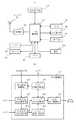
次に、本発明の実施の形態について図面を参照して詳細に説明する。図1(a)は本発明の第1の実施の形態における携帯電話機の構成を示すブロック図であり、(b)は(a)の中央制御部における本発明に係わる部分を示すブロック図である。
【0021】
図1を参照すると、携帯電話機は、受光検出部10、カメラ20、LCD(Liquid Crystal Display:液晶表示)表示部30、中央制御部40、無線部50、アンテナ51、操作部60、マイク70、電池80、スピーカ90を備える。中央制御部40は、マイクロプロセッサ等により構成されるコンピュータ相当の機能を有し、操作部60より入力されるユーザー操作を検出し、ユーザー操作に基づいた表示処理を行うと共にメモリ41に格納したプログラムにより携帯電話機各部の制御を行う。無線部50は、中央制御部40の制御により、アンテナ51を介して受信した電波を復調し、および変調した電波をアンテナ51を介して送信する。通話時、マイク70から入力したアナログ音声を中央制御部40にてデジタル変換し、無線部50およびアンテナ51を介して送信する。アンテナ51、無線部50を介して受信した音声データは、中央制御部40にてアナログ変換し、スピーカ90より出力する。カメラ20は、中央制御部40の制御により、撮影した画像データを中央制御部40に出力する。LCD表示部30は、中央制御部40の制御により、各種の表示を行う。カメラファインダ時は、中央制御部40にてカメラ20からの画像データを表示データ形式に変換し、LCD表示部30に撮影画像を表示する。受光検出部10は、中央制御部40の制御により、照射された光量を測定し、予め定める一定値との比較結果を中央制御部40に出力する。
【0022】
中央制御部40は、カメラ起動制御部401と、受光検出制御部402と、受光状態設定制御部403と、受光状態変化判定部404と、フラッシュ設定判定部405と、ファインダ表示制御部406と、LCD表示制御部407とを備える。カメラ起動制御部401はカメラ20の起動・停止制御を行う。受光検出制御部402は、カメラ起動制御部401により起動され受光検出部10の起動およびデータ格納指示を行うと共に受光検出部10が検出した明暗状態を認識する。受光状態設定制御部403は、受光検出制御部402によって確認された明るさと暗さの状態変化をメモリ41に設定格納する。受光状態変化判定部404は、メモリ41に格納された変化後の明暗状態を判定する。フラッシュ設定判定部405は、受光状態変化判定部404の判定が明るい場合にファインダ表示を継続させ受光状態変化判定部404の判定が暗い場合にはカメラフラッシュの設定有無を判断する。ファインダ表示制御部406は、受光状態変化判定部404の判定が明るい場合およびカメラフラッシュが設定されている場合にはファインダ表示を継続させ暗い場合且つフラッシュ設定がなされていない場合にはファインダ表示を停止させカメラ起動制御部401および受光検出制御部402に起動停止を指示する。LCD表示制御部407は、ファインダ表示制御部406の指示に基づきLCD表示部30の表示制御を行う。
【0023】
図2(a)は図1(a)における受光検出部の構成を示すブロック図であり、図2(b)は図2(a)における比較器の構成を示すブロック図である。受光検出部10は、受光部1と、変換器2と、比較器3とで構成する。比較器3は、測定結果格納用レジスタ31(以降、レジスタ31と略称)、電圧しきい値格納用レジスタ32(以降、レジスタ32と略称)、A/D変換要求間隔時間格納用レジスタ33(以降、レジスタ33と略称)、比較結果格納用レジスタ34(以降、レジスタ33と略称)、カウンタ35を備える。
【0024】
受光部1は受光した光量を電圧変換して出力し、変換器2は比較器3からのA/D要求により、受光部1からのアナログ電圧をデジタル値に変換し、レジスタ31に格納する。レジスタ32には、中央制御部40により、予め定めた電圧しきい値を格納する。レジスタ33には、中央制御部40により、変換器2へのA/D変換要求出力間隔値を格納する。レジスタ34にはレジスタ31に格納された測定結果とレジスタ32に格納されたしきい値との比較結果を保存する。カウンタ35は中央制御部40の制御により起動し、比較器3は、レジスタ33とカウンタ値の一致を検出した場合、変換器2へA/D変換要求を出力し、カウンタ35をリセットスタートする。比較器3は、レジスタ31のデータ更新時にレジスタ32の値と比較し、レジスタ34に格納する。レジスタ34値が前の値と異なる時は、中央制御部40に通知する。
【0025】
次に、本発明の第1の実施の形態の動作について図1〜図3を参照して説明する。ユーザー操作による操作部60の入力により、中央制御部40のカメラ起動制御部401がカメラ20を起動する(ステップ301:S301と呼称、以降同様)。中央制御部40の受光検出制御部402は受光検出部10を起動する(S302)。中央制御部40のLCD表示制御部407は、LCD表示部30にファインダ表示を開始する(S303)。
【0026】
カメラ起動制御部401はカメラ起動を継続、終了の判断において(S304)、カメラ起動を継続する場合、受光検出部10は明るさと暗さの状態変化を確認する(S305)。状態変化がある場合、受光検出制御部402は受光検出部10のレジスタ34に格納された値を確認し、中央制御部40の受光状態設定制御部403がメモリ41に変化後状態として、明るいか暗いかを設定する(S306)。
【0027】
中央制御部40の受光状態変化判定部404は、メモリ41に格納した変化後状態を確認して、暗さの変化後を判断し(S307)、明るい場合はファインダ表示を継続し(S303)、暗い場合はカメラフラッシュ設定の有無を判断する(S308)。変化後状態が暗い場合、カメラフラッシュ設定されていなければ、中央制御部40のファインダ表示制御部406は、カメラ起動終了を認識してLCD表示制御部407にファインダ表示の停止を指示する(S309)。一方、カメラフラッシュが設定されているならば、ファインダ表示を継続する(S303)。ファインダ表示制御部406は、カメラファインダ表示の停止指示を行うと、カメラ起動制御部401を介し受光検出部10、カメラ20の起動停止を行い(S310、311)、LCD表示部30を待ち受け画面へ遷移させる(S312)。
【0028】
次に、 受光検出部10の起動時の動作について図4を用いて説明する。本処理はカメラ起動中に実施する。レジスタ32は受光検出制御部402により、明るいか暗いかの基準値である電圧しきい値を保存する(S401)。レジスタ33は受光検出制御部402により変換器2へA/D変換要求を行う間隔(時間)を保存する(S402)。カウンタ35は、受光検出制御部402によりカウント開始し(S403)、レジスタ33とカウンタ値が一致するまで行い(S403)、一致した場合、比較器3は変換器2へA/D変換要求を出力し(S405)、カウンタ35をリセットスタートする(S406)。
【0029】
変換器2は比較器3のA/D変換要求により、アナログ電圧値をデジタル電圧値に変換しこの電圧値をレジスタ31へ格納する(S407)。比較器3は変換器2がレジスタ31にデータを格納したことをトリガとし、レジスタ32に格納した値との比較を行い(S408)、大か小の結果をレジスタ34へ格納する(S409)。大の場合は明るいとなり、小の場合は暗いとなる。前の値と同じならば、比較器3はレジスタ34へ同値を格納する。比較器3は、レジスタ34値に前回比較結果と異なる値を格納すると(S410)、格納したタイミングをトリガとし、明るいか暗いかの状態変化が発生したことを受光検出制御部402通知する(S411)。受光検出制御部402への通知完了後、比較器3はレジスタ33に格納した値とカウンタ値の比較処理を行う(S404)。
【0030】
次に、第2の実施の形態について図面を参照して説明する。
【0031】
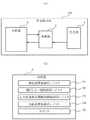
上述した第1の実施の形態では、中央制御部40で認識している状態が暗い、且つカメラフラッシュ設定有りのときにカメラ20を停止し待ち受け画面へ遷移する場合を説明したが、ファインダ表示時にシャッター押下を受け付けないことで、ファインダ表示中の撮影を停止することも可能である。 図5は第2の実施の形態における中央制御部40aを示すブロック図である。図5を参照すると、上述した図1(b)に示された構成に対し、シャッター不動作制御部408がさらに追加されている。シャッター不動作制御部408は、受光状態変化判定部404により変化後の状態が暗いと判定され且つフラッシュ設定判定部405がフラッシュ設定無しと判定した場合、ファインダ表示時にシャッター押下を無効とする。なお、図1(a)を含めその他の各部は第1の実施の形態と同じなので説明を省略する。
【0032】
次に、第2の実施の形態の動作を説明する。第2の実施の形態の処理動作を示す図6を参照すると、図6のS601からS604、S610からS613までの処理動作は第1の実施の形態における図3のS301からS304、S309からS312までと同様であり、また図6のS605からS607は、図3のS305からS307までと同一処理なため、ここでは説明を省略し、S608以降の処理について説明する。
【0033】
受光状態変化判定部404により変化後状態が暗く(S607)、且つフラッシュ設定判定部405によりカメラフラッシュ設定の有無を判断し(S608)、カメラフラッシュ設定有りの場合、LCD表示部30にファインダ表示を継続する(S603)。一方、カメラフラッシュ設定無しの場合、中央制御部40のシャッター不動作制御部408は、図1の操作部60入力によるシャッター押下を受け付けない(S609)。このS609処理完了後、中央制御部40はLCD表示部30にファインダ表示を継続する(S603)。 シャッター不動作制御部408がシャッター押下を受け付けない状態は、フラッシュ設定有りへの変更、もしくは変化後状態が明るいことを検出するまで継続する。
【0034】
次に、本発明の第3の実施の形態について図面を参照して説明する。
【0035】
図7を参照すると、上述した図5に示された構成に対し、中央制御部40bでは、報知出力制御部409がさらに追加されている。報知出力制御部409は、シャッター不動作制御部408が動作したとき特定の報知音あるいはバイブレータを動作させる。なお、図1(a)を含めその他の各部は第2の実施の形態と同じなので説明を省略する。この第3の実施の形態の場合、カメラフラッシュが設定されていない状態で、シャッター押下を受け付けない場合、特定の報知音(または特定メッセージでもよい)あるいはバイブレータを動作させることにより、周囲に対し知らせ、あるいは振動による撮影を不能にすることができるので、盗撮をより有効に防止することが可能となる。
【0036】
【発明の効果】
以上説明したとおり本発明によれば、カメラ付き携帯電話機でカメラフラッシュ設定無しの状態で暗い状態を検出した場合に、カメラ機能を停止する機能を付加することにより盗撮を防止することができる。
【図面の簡単な説明】
【図1】(a)は本発明の第1の実施の形態における携帯電話機の構成を示すブロック図である。(b)は(a)の中央制御部における本発明に係わる部分を示すブロック図である。
【図2】(a)は図1(a)における受光検出部の構成を示すブロック図である。(b)は(a)における比較器の構成を示すブロック図である。
【図3】本発明の第1の実施の形態の動作を説明するためのフローチャートである。
【図4】本発明における比較器に係わる動作を説明するためのフローチャートである。
【図5】本発明の第2の実施の形態における中央制御部の構成を示すブロック図である。
【図6】本発明の第2の実施の形態の動作を説明するためのフローチャートである。
【図7】本発明の第3の実施の形態における中央制御部の構成を示すブロック図である。
【符号の説明】
1 受光部
2 変換器
3 比較器
10 受光検出部
20 カメラ
30 LCD表示部
31 測定結果格納用レジスタ
32 電圧しきい値格納用レジスタ
33 A/D変換要求間隔時間格納用レジスタ
34 比較結果格納用レジスタ
35 カウンタ
40,40a,40b 中央制御部
41 メモリ
50 無線部
51 アンテナ
60 操作部
70 マイク
80 電池
90 スピーカ
401 カメラ起動制御部
402 受光検出制御部
403 受光状態設定制御部
404 受光状態変化判定部
405 フラッシュ設定判定部
406 ファインダ表示制御部
407 LCD表示制御部
408 シャッター不動作制御部
409 報知出力制御部[0001]
BACKGROUND OF THE INVENTION
The present invention relates to a camera-equipped mobile phone, and more particularly to a shooting stop function in a camera-equipped mobile phone.
[0002]
[Prior art]
2. Description of the Related Art Conventionally, camera-equipped mobile phones notify the surroundings that a shutter has been pressed by sounding the shutter sound during shooting, and this shutter sound plays a role in preventing voyeurism at close range. In addition, as a technique related to the prevention of voyeurism, an imaging apparatus is disclosed that stops an imaging function by detecting voyeurism prevention information generated from a voyeurism prevention information generation apparatus attached to a subject that is not desired to be imaged (for example, Patent Document 1). Alternatively, a mobile terminal is disclosed in which an optical sensor is provided and activated when the touch panel is tapped when the surrounding is bright and is not activated when the surrounding is dark. Thus, a portable terminal that can prevent the automatic activation of the portable terminal and save power even if tapped on the touch panel when put in a bag or the like is disclosed (for example, see Patent Document 2). ).
[0003]
[Patent Document 1]
JP 2001-169175 A (paragraph number 0151)
[Patent Document 2]
JP 2001-069235 A (paragraph number 0037)
[0004]
[Problems to be solved by the invention]
However, there are cases where the shutter sound is not noticed in a place where people are concentrated, and it cannot always be said that it is a perfect countermeasure. In addition, when considering voyeurism in a place where people are concentrated, the camera-equipped mobile phone tends to shoot with the camera-mounted mobile phone hidden, and the camera-equipped mobile phone is placed in a dark environment.
[0005]
An object of the present invention is to provide a camera-equipped mobile phone capable of stopping a camera function when a dark state is detected without a camera flash setting and preventing voyeurism, a method for stopping the shooting, and a program therefor. is there.
[0006]
[Means for Solving the Problems]
The present invention according to claim 1 is a camera-equipped mobile phone having a light receiving detection means for detecting ambient illuminance, and the camera flash is in a non-set state and a dark state with a constant light amount when the camera mode is activated. When it is detected that there has been a change, a control unit is provided that interrupts the camera function and disallows shooting.
[0019]
According to the present invention, in a camera-equipped mobile phone, an optical sensor is attached in the vicinity of the front LCD, the camera flash is not set, and the camera function is interrupted by detecting a certain amount of light loss, so that the camera cannot be photographed. Can be.
[0020]
DETAILED DESCRIPTION OF THE INVENTION
Next, embodiments of the present invention will be described in detail with reference to the drawings. FIG. 1A is a block diagram showing a configuration of a mobile phone according to a first embodiment of the present invention, and FIG. 1B is a block diagram showing a portion related to the present invention in a central control unit of FIG. .
[0021]
Referring to FIG. 1, the mobile phone includes a light
[0022]
The
[0023]
FIG. 2A is a block diagram showing the configuration of the light receiving detector in FIG. 1A, and FIG. 2B is a block diagram showing the configuration of the comparator in FIG. 2A. The light
[0024]
The light receiving unit 1 converts the received light amount into a voltage and outputs it, and the converter 2 converts the analog voltage from the light receiving unit 1 into a digital value in response to an A / D request from the comparator 3 and stores it in the
[0025]
Next, the operation of the first embodiment of the present invention will be described with reference to FIGS. The camera
[0026]
When the camera
[0027]
The light reception state
[0028]
Next, the operation at the time of activation of the light
[0029]
In response to the A / D conversion request from the comparator 3, the converter 2 converts the analog voltage value into a digital voltage value, and stores this voltage value in the register 31 (S407). The comparator 3 uses the data stored in the
[0030]
Next, a second embodiment will be described with reference to the drawings.
[0031]
In the first embodiment described above, a case has been described in which the state recognized by the
[0032]
Next, the operation of the second embodiment will be described. Referring to FIG. 6 showing the processing operation of the second embodiment, the processing operations from S601 to S604 and S610 to S613 in FIG. 6 are from S301 to S304 and S309 to S312 in FIG. 3 in the first embodiment. 6 and S605 to S607 in FIG. 6 are the same as S305 to S307 in FIG. 3, and thus the description is omitted here, and the processing after S608 will be described.
[0033]
When the light receiving state
[0034]
Next, a third embodiment of the present invention will be described with reference to the drawings.
[0035]
Referring to FIG. 7, a notification
[0036]
【The invention's effect】
As described above, according to the present invention, it is possible to prevent voyeurism by adding a function of stopping the camera function when a dark state is detected with a camera-equipped mobile phone without camera flash setting.
[Brief description of the drawings]
FIG. 1A is a block diagram showing a configuration of a mobile phone according to a first embodiment of the present invention. (B) is a block diagram which shows the part concerning this invention in the central control part of (a).
FIG. 2A is a block diagram illustrating a configuration of a light reception detection unit in FIG. (B) is a block diagram showing a configuration of a comparator in (a).
FIG. 3 is a flowchart for explaining the operation of the first exemplary embodiment of the present invention;
FIG. 4 is a flowchart for explaining an operation related to a comparator in the present invention;
FIG. 5 is a block diagram illustrating a configuration of a central control unit according to a second embodiment of the present invention.
FIG. 6 is a flowchart for explaining the operation of the second exemplary embodiment of the present invention;
FIG. 7 is a block diagram illustrating a configuration of a central control unit according to a third embodiment of the present invention.
[Explanation of symbols]
DESCRIPTION OF SYMBOLS 1 Light-receiving part 2 Converter 3
Claims (1)
Translated fromJapanesePriority Applications (1)
| Application Number | Priority Date | Filing Date | Title |
|---|---|---|---|
| JP2003179087AJP3872041B2 (en) | 2003-06-24 | 2003-06-24 | Mobile phone with camera, method for stopping shooting thereof, and program |
Applications Claiming Priority (1)
| Application Number | Priority Date | Filing Date | Title |
|---|---|---|---|
| JP2003179087AJP3872041B2 (en) | 2003-06-24 | 2003-06-24 | Mobile phone with camera, method for stopping shooting thereof, and program |
Publications (2)
| Publication Number | Publication Date |
|---|---|
| JP2005020130A JP2005020130A (en) | 2005-01-20 |
| JP3872041B2true JP3872041B2 (en) | 2007-01-24 |
Family
ID=34180491
Family Applications (1)
| Application Number | Title | Priority Date | Filing Date |
|---|---|---|---|
| JP2003179087AExpired - Fee RelatedJP3872041B2 (en) | 2003-06-24 | 2003-06-24 | Mobile phone with camera, method for stopping shooting thereof, and program |
Country Status (1)
| Country | Link |
|---|---|
| JP (1) | JP3872041B2 (en) |
Cited By (19)
| Publication number | Priority date | Publication date | Assignee | Title |
|---|---|---|---|---|
| CN111901480A (en)* | 2019-05-06 | 2020-11-06 | 苹果公司 | User interface for capturing and managing visual media |
| US11039074B1 (en) | 2020-06-01 | 2021-06-15 | Apple Inc. | User interfaces for managing media |
| US11102414B2 (en) | 2015-04-23 | 2021-08-24 | Apple Inc. | Digital viewfinder user interface for multiple cameras |
| US11112964B2 (en) | 2018-02-09 | 2021-09-07 | Apple Inc. | Media capture lock affordance for graphical user interface |
| US11128792B2 (en) | 2018-09-28 | 2021-09-21 | Apple Inc. | Capturing and displaying images with multiple focal planes |
| US11165949B2 (en) | 2016-06-12 | 2021-11-02 | Apple Inc. | User interface for capturing photos with different camera magnifications |
| US11178335B2 (en) | 2018-05-07 | 2021-11-16 | Apple Inc. | Creative camera |
| US11204692B2 (en) | 2017-06-04 | 2021-12-21 | Apple Inc. | User interface camera effects |
| US11212449B1 (en) | 2020-09-25 | 2021-12-28 | Apple Inc. | User interfaces for media capture and management |
| US11223771B2 (en) | 2019-05-06 | 2022-01-11 | Apple Inc. | User interfaces for capturing and managing visual media |
| US11321857B2 (en) | 2018-09-28 | 2022-05-03 | Apple Inc. | Displaying and editing images with depth information |
| US11350026B1 (en) | 2021-04-30 | 2022-05-31 | Apple Inc. | User interfaces for altering visual media |
| US11706521B2 (en) | 2019-05-06 | 2023-07-18 | Apple Inc. | User interfaces for capturing and managing visual media |
| US11722764B2 (en) | 2018-05-07 | 2023-08-08 | Apple Inc. | Creative camera |
| US11770601B2 (en) | 2019-05-06 | 2023-09-26 | Apple Inc. | User interfaces for capturing and managing visual media |
| US11778339B2 (en) | 2021-04-30 | 2023-10-03 | Apple Inc. | User interfaces for altering visual media |
| US12112024B2 (en) | 2021-06-01 | 2024-10-08 | Apple Inc. | User interfaces for managing media styles |
| US12154218B2 (en) | 2018-09-11 | 2024-11-26 | Apple Inc. | User interfaces simulated depth effects |
| US12401889B2 (en) | 2023-05-05 | 2025-08-26 | Apple Inc. | User interfaces for controlling media capture settings |
Families Citing this family (3)
| Publication number | Priority date | Publication date | Assignee | Title |
|---|---|---|---|---|
| JP2009141501A (en)* | 2007-12-04 | 2009-06-25 | Fujitsu Ltd | Portable imaging device and computer program |
| JP5119136B2 (en)* | 2008-12-03 | 2013-01-16 | 富士フイルム株式会社 | Electronic device and control method thereof |
| WO2020161861A1 (en)* | 2019-02-07 | 2020-08-13 | オリンパス株式会社 | Imaging device and program |
- 2003
- 2003-06-24JPJP2003179087Apatent/JP3872041B2/ennot_activeExpired - Fee Related
Cited By (44)
| Publication number | Priority date | Publication date | Assignee | Title |
|---|---|---|---|---|
| US11711614B2 (en) | 2015-04-23 | 2023-07-25 | Apple Inc. | Digital viewfinder user interface for multiple cameras |
| US11102414B2 (en) | 2015-04-23 | 2021-08-24 | Apple Inc. | Digital viewfinder user interface for multiple cameras |
| US11490017B2 (en) | 2015-04-23 | 2022-11-01 | Apple Inc. | Digital viewfinder user interface for multiple cameras |
| US12149831B2 (en) | 2015-04-23 | 2024-11-19 | Apple Inc. | Digital viewfinder user interface for multiple cameras |
| US11245837B2 (en) | 2016-06-12 | 2022-02-08 | Apple Inc. | User interface for camera effects |
| US11641517B2 (en) | 2016-06-12 | 2023-05-02 | Apple Inc. | User interface for camera effects |
| US11962889B2 (en) | 2016-06-12 | 2024-04-16 | Apple Inc. | User interface for camera effects |
| US11165949B2 (en) | 2016-06-12 | 2021-11-02 | Apple Inc. | User interface for capturing photos with different camera magnifications |
| US12132981B2 (en) | 2016-06-12 | 2024-10-29 | Apple Inc. | User interface for camera effects |
| US12314553B2 (en) | 2017-06-04 | 2025-05-27 | Apple Inc. | User interface camera effects |
| US11687224B2 (en) | 2017-06-04 | 2023-06-27 | Apple Inc. | User interface camera effects |
| US11204692B2 (en) | 2017-06-04 | 2021-12-21 | Apple Inc. | User interface camera effects |
| US11977731B2 (en) | 2018-02-09 | 2024-05-07 | Apple Inc. | Media capture lock affordance for graphical user interface |
| US11112964B2 (en) | 2018-02-09 | 2021-09-07 | Apple Inc. | Media capture lock affordance for graphical user interface |
| US11178335B2 (en) | 2018-05-07 | 2021-11-16 | Apple Inc. | Creative camera |
| US11722764B2 (en) | 2018-05-07 | 2023-08-08 | Apple Inc. | Creative camera |
| US12170834B2 (en) | 2018-05-07 | 2024-12-17 | Apple Inc. | Creative camera |
| US12154218B2 (en) | 2018-09-11 | 2024-11-26 | Apple Inc. | User interfaces simulated depth effects |
| US11321857B2 (en) | 2018-09-28 | 2022-05-03 | Apple Inc. | Displaying and editing images with depth information |
| US11128792B2 (en) | 2018-09-28 | 2021-09-21 | Apple Inc. | Capturing and displaying images with multiple focal planes |
| US11895391B2 (en) | 2018-09-28 | 2024-02-06 | Apple Inc. | Capturing and displaying images with multiple focal planes |
| US12394077B2 (en) | 2018-09-28 | 2025-08-19 | Apple Inc. | Displaying and editing images with depth information |
| US11669985B2 (en) | 2018-09-28 | 2023-06-06 | Apple Inc. | Displaying and editing images with depth information |
| US11223771B2 (en) | 2019-05-06 | 2022-01-11 | Apple Inc. | User interfaces for capturing and managing visual media |
| CN111901480A (en)* | 2019-05-06 | 2020-11-06 | 苹果公司 | User interface for capturing and managing visual media |
| CN111901480B (en)* | 2019-05-06 | 2021-05-28 | 苹果公司 | User interface for capturing and managing visual media |
| US11770601B2 (en) | 2019-05-06 | 2023-09-26 | Apple Inc. | User interfaces for capturing and managing visual media |
| US11706521B2 (en) | 2019-05-06 | 2023-07-18 | Apple Inc. | User interfaces for capturing and managing visual media |
| US12192617B2 (en) | 2019-05-06 | 2025-01-07 | Apple Inc. | User interfaces for capturing and managing visual media |
| US11617022B2 (en) | 2020-06-01 | 2023-03-28 | Apple Inc. | User interfaces for managing media |
| US11039074B1 (en) | 2020-06-01 | 2021-06-15 | Apple Inc. | User interfaces for managing media |
| US11054973B1 (en) | 2020-06-01 | 2021-07-06 | Apple Inc. | User interfaces for managing media |
| US12081862B2 (en) | 2020-06-01 | 2024-09-03 | Apple Inc. | User interfaces for managing media |
| US11330184B2 (en) | 2020-06-01 | 2022-05-10 | Apple Inc. | User interfaces for managing media |
| US11212449B1 (en) | 2020-09-25 | 2021-12-28 | Apple Inc. | User interfaces for media capture and management |
| US12155925B2 (en) | 2020-09-25 | 2024-11-26 | Apple Inc. | User interfaces for media capture and management |
| US11418699B1 (en) | 2021-04-30 | 2022-08-16 | Apple Inc. | User interfaces for altering visual media |
| US12101567B2 (en) | 2021-04-30 | 2024-09-24 | Apple Inc. | User interfaces for altering visual media |
| US11350026B1 (en) | 2021-04-30 | 2022-05-31 | Apple Inc. | User interfaces for altering visual media |
| US11416134B1 (en) | 2021-04-30 | 2022-08-16 | Apple Inc. | User interfaces for altering visual media |
| US11778339B2 (en) | 2021-04-30 | 2023-10-03 | Apple Inc. | User interfaces for altering visual media |
| US11539876B2 (en) | 2021-04-30 | 2022-12-27 | Apple Inc. | User interfaces for altering visual media |
| US12112024B2 (en) | 2021-06-01 | 2024-10-08 | Apple Inc. | User interfaces for managing media styles |
| US12401889B2 (en) | 2023-05-05 | 2025-08-26 | Apple Inc. | User interfaces for controlling media capture settings |
Also Published As
| Publication number | Publication date |
|---|---|
| JP2005020130A (en) | 2005-01-20 |
Similar Documents
| Publication | Publication Date | Title |
|---|---|---|
| JP3872041B2 (en) | Mobile phone with camera, method for stopping shooting thereof, and program | |
| EP2057837B1 (en) | Electronic device with auxiliary camera function | |
| JP2001086393A (en) | Mobile communication device | |
| WO2015092689A1 (en) | Alternative input device for press/release simulations | |
| KR100636452B1 (en) | Portable terminal and announcement method thereof | |
| US7576785B2 (en) | Apparatus and method for compensating for backlight in a mobile terminal with a camera | |
| US20050128315A1 (en) | Data processing apparatus, data processing method, and computer program | |
| US7499642B2 (en) | Portable electronic device and method of preventing close-up photography by using the portable electronic device | |
| KR20060024349A (en) | Electronic device, operation control method and operation control program with image capture and wireless communication function | |
| JP2002290818A (en) | Portable terminal | |
| US20080273871A1 (en) | Image Pickup Terminal | |
| KR20040101543A (en) | Portable telephone apparatus | |
| JP5280185B2 (en) | Portable terminal and electronic camera | |
| KR100733102B1 (en) | Electronic apparatus, method for switching focusing mode and recording medium on which software program for switching focusing mode is recorded | |
| KR100793295B1 (en) | Camera mode control method using pressure sensor and mobile communication terminal for performing the same | |
| KR100513053B1 (en) | Auto controlling method for previewing image data | |
| CN106170038B (en) | Recording method and device | |
| JP2003348211A (en) | Portable terminal and its notification method | |
| US20090284636A1 (en) | Device for displaying taken image and method of displaying taken image | |
| JP2006038991A (en) | Portable device, photographing control method, and photographing control program | |
| JP2010258753A (en) | Mobile terminal and projection program | |
| JP3842652B2 (en) | Mobile communication terminal | |
| JP2004138890A (en) | Mobile electronic equipment | |
| JP2003219243A (en) | Image photographing device and program | |
| KR100835377B1 (en) | Continuous shooting method and apparatus of a mobile terminal having a camera function |
Legal Events
| Date | Code | Title | Description |
|---|---|---|---|
| RD01 | Notification of change of attorney | Free format text:JAPANESE INTERMEDIATE CODE: A7421 Effective date:20050328 | |
| A977 | Report on retrieval | Free format text:JAPANESE INTERMEDIATE CODE: A971007 Effective date:20060707 | |
| A131 | Notification of reasons for refusal | Free format text:JAPANESE INTERMEDIATE CODE: A131 Effective date:20060718 | |
| A521 | Request for written amendment filed | Free format text:JAPANESE INTERMEDIATE CODE: A523 Effective date:20060907 | |
| TRDD | Decision of grant or rejection written | ||
| A01 | Written decision to grant a patent or to grant a registration (utility model) | Free format text:JAPANESE INTERMEDIATE CODE: A01 Effective date:20061003 | |
| A61 | First payment of annual fees (during grant procedure) | Free format text:JAPANESE INTERMEDIATE CODE: A61 Effective date:20061018 | |
| R150 | Certificate of patent or registration of utility model | Free format text:JAPANESE INTERMEDIATE CODE: R150 | |
| FPAY | Renewal fee payment (event date is renewal date of database) | Free format text:PAYMENT UNTIL: 20091027 Year of fee payment:3 | |
| FPAY | Renewal fee payment (event date is renewal date of database) | Free format text:PAYMENT UNTIL: 20101027 Year of fee payment:4 | |
| LAPS | Cancellation because of no payment of annual fees |