JP3872039B2 - Wireless base station system - Google Patents
Wireless base station systemDownload PDFInfo
- Publication number
- JP3872039B2 JP3872039B2JP2003162277AJP2003162277AJP3872039B2JP 3872039 B2JP3872039 B2JP 3872039B2JP 2003162277 AJP2003162277 AJP 2003162277AJP 2003162277 AJP2003162277 AJP 2003162277AJP 3872039 B2JP3872039 B2JP 3872039B2
- Authority
- JP
- Japan
- Prior art keywords
- transmission
- signal
- reception
- unit
- spreading code
- Prior art date
- Legal status (The legal status is an assumption and is not a legal conclusion. Google has not performed a legal analysis and makes no representation as to the accuracy of the status listed.)
- Expired - Fee Related
Links
- 230000005540biological transmissionEffects0.000claimsdescription447
- 239000002131composite materialSubstances0.000claimsdescription72
- 238000012545processingMethods0.000claimsdescription67
- 238000000034methodMethods0.000claimsdescription34
- 238000005259measurementMethods0.000claimsdescription29
- 230000008054signal transmissionEffects0.000claimsdescription14
- 238000004891communicationMethods0.000claimsdescription8
- 239000000284extractSubstances0.000claimsdescription2
- 230000003287optical effectEffects0.000description38
- 238000006243chemical reactionMethods0.000description26
- 238000010586diagramMethods0.000description19
- 239000013307optical fiberSubstances0.000description11
- 238000000926separation methodMethods0.000description8
- 238000009792diffusion processMethods0.000description4
- 238000012544monitoring processMethods0.000description4
- 230000005611electricityEffects0.000description3
- 108010003272Hyaluronate lyaseProteins0.000description2
- 230000000694effectsEffects0.000description2
- 230000000737periodic effectEffects0.000description2
- 238000012937correctionMethods0.000description1
- 238000009432framingMethods0.000description1
- 238000003780insertionMethods0.000description1
- 230000037431insertionEffects0.000description1
- 238000010295mobile communicationMethods0.000description1
- 230000001360synchronised effectEffects0.000description1
- 230000002194synthesizing effectEffects0.000description1
Images


Landscapes
- Mobile Radio Communication Systems (AREA)
Description
Translated fromJapanese【0001】
【発明の属する技術分野】
本発明は無線基地局システムに関し、特に無線基地局装置と遠方の無線送受信部間との伝送信号をCDMA方式により多重化し、既存のサービスを停止することなく無線基地局装置と遠方の無線送受信部との遅延時間を高精度に測定できる無線基地局システムに関する。
【0002】
【従来の技術】
一般に、送受信アンテナが複数個遠方にある無線基地局システムにおいては、時分割多重化方式で各送受信アンテナの信号を多重している。
【0003】
図9は従来の時分割方式での伝送フォーマットを示す図である。
【0004】
このような時分割方式で遅延時間を測定しようとした場合、例えば8本のアンテナ1用〜アンテナ8用の送受信アンテナをサポートするシステムでは、図9に示すように各送受信アンテナに割り当てられる時間は全体の時間の1/8であるため、1/8の単位でしか遅延量の測定精度はない。
【0005】
また、この例の場合は送受信アンテナ1用〜アンテナ8用のすべてのデータを遅延量測定のための制御信号に割り当てた場合で、運用中に遅延量を再度測定したい場合はベースバンド信号を停止する必要があるため、一旦運用中のサービスを停止する必要がある。
【0006】
遅延時間の調整では、遅延時間測定器を用いて遅延時間を測定し、この測定結果をもとに遅延時間可変要求が調整されている。
【0007】
本発明の目的は、送受信アンテナが複数個遠方にある無線基地局システムにおいて、無線基地局装置と遠方の無線送受信部送受信アンテナ間との伝送信号をデジタル信号とし、送信側で複数の送受信アンテナのデジタル信号をCDMA(Code Division Multiple Access)方式により多重し、受信側で複数の送受信アンテナのデジタル信号を分離することにより既存のサービスを停止することなく、無線基地局装置と遠方の無線送受信部送受信アンテナ間との遅延時間を高精度に測定できる無線基地局システムを供給できることにある。
【0008】
従来の無線基地局システムは、基地局の可変指向性アンテナ各素子の信号を時分割多重装置で時分割多重し、この時分割多重された信号を同一の光ファイバ内を伝送させることでアンテナ各素子間の相対位置変化をなくし、アンテナ各素子間の相対位相差を維持している(例えば、特許文献1参照。)。
【0009】
また、集中基地局に送受信装置を設置し、無線基地局に送受信アンテナを設置して無線基地局と集中基地局との間を伝送路で接続し、送受信装置と送受信アンテナ間の信号を伝送するための全二重基地局間伝送路を含む基地局装置及び伝送路の状態を監視しているものもある(例えば、特許文献2参照。)。
【0010】
【特許文献1】
特開2001−94332号公報(第3−5頁、図1、図2)
【特許文献2】
特開平5−327632号公報(第2−3頁、図1)
【0011】
【発明が解決しようとする課題】
上述した従来の無線基地局システムは、このような時分割方式で遅延時間を測定しようとした場合、各送受信アンテナに割り当てられる時間は全体の時間の1/8であるため、1/8の単位でしか遅延量の測定精度がないという欠点を有している。
【0012】
また、送受信アンテナ1用〜アンテナ8用のすべてのデータを遅延量測定のための制御信号に割り当てた場合、運用中に遅延量を再度測定したい場合はベースバンド信号を停止する必要があるため、一旦運用中のサービスを停止する必要があるという欠点を有している。
【0013】
本発明の目的は、送受信アンテナを有す無線送受信部が複数個遠方にある無線基地局システムにおいて、無線基地局装置と無線送受信部の送受信アンテナ間の伝送信号をデジタル信号とし、送信側で複数の送受信アンテナのデジタル信号をCDMA方式により多重し、受信側で複数の送受信アンテナのデジタル信号を分離することにより既存のサービスを停止することなく、無線基地局装置と遠方の無線送受信部送受信アンテナ間との遅延時間を高精度に測定できる無線基地局システムを提供することにある。
【0014】
【課題を解決するための手段】
本発明の第1の無線基地局システムは、無線基地局装置と、前記無線基地局装置と信号送受信路がカスケードに接続された複数の無線送受信部とを有する無線基地局システムであって、前記無線基地局装置は、前記無線送受信部に送信する各送信信号を、前記無線送受信部を識別する第一の拡散コードと遅延時間測定に用いる第二の拡散コードとで拡散し、この拡散された信号をCDMA方式により多重して送信多重化信号として出力する送信処理手段と、前記無線送受信部から受信した受信多重化信号を、前記第一の拡散コードと前記第二の拡散コードとで逆拡散し、前記無線送受信部から受信した受信信号として出力する受信処理手段と、前記送信処理手段による前記第二の拡散コードを用いた拡散処理により求めた拡散タイミング信号と、前記受信処理手段による前記第二の拡散コードを用いた逆拡散処理により求めた逆拡散タイミング信号とを入力し送受信信号の遅延時間を求める遅延測定手段と、を備え、前記無線送受信部は、前記無線基地局装置が出力する送信多重化信号を、カスケードに接続された他の無線送受信部に出力する第1の送信多重化信号と自無線送受信部で処理する第2の送信多重化信号とに分離する分離手段と、前記第2の送信多重化信号を、自無線送受信部を識別する第一の拡散コードと遅延時間測定に用いる第二の拡散コードとで逆拡散し、自無線送受信部に対応する送信信号をアンテナ部を介して出力する第2の送信処理手段と、アンテナ部を介して受信した受信信号を、第一の拡散コードと第二の拡散コードとを用いて、前記第2の送信処理手段で前記第二の拡散コードを用いた逆拡散処理により求めた先頭タイミングで拡散して出力する受信手段と、前記受信手段から入力する拡散された信号と、カスケードに接続された他の無線送受信部から入力する第1の受信多重化信号とを多重して第2の受信多重化信号として出力する多重手段とを備えることを特徴とする。
【0015】
本発明の第2の無線基地局システムは、信号送受信路がカスケードに接続された複数の無線送受信部に送信する各送信信号を、前記無線送受信部を識別する第一の拡散コードと遅延時間測定に用いる第二の拡散コードとで拡散し、当該拡散された各送信信号をCDMA方式により多重して送信多重化信号として前記無線送受信部に出力し、前記無線送受信部から入力した受信多重化信号を前記第一の拡散コードと前記第二の拡散コードとで逆拡散し、前記複数の無線送受信部から受信した各受信信号を生成する無線基地局装置と、前記送信多重化信号を入力し、前記第一の拡散コードと前記第二の拡散コードで逆拡散して抽出した送信信号を、アンテナ部を介して出力し、アンテナ部を介して受信した信号を前記第一の拡散コードと前記第二の拡散コードとを用いて、前記送信多重化信号の逆拡散で用いた前記第二の拡散コードの逆拡散タイミングで拡散した拡散受信信号を生成し受信多重化信号として出力する無線送受信部とを備え、前記無線送受信部は、カスケード接続された無線送受信部が出力する受信多重化信号と無線送受信部で生成した前記拡散受信信号とを多重して、前記受信多重化信号を出力する無線送受信部とは異なる無線送受信部または前記無線基地局装置のいずれかに出力し、前記無線基地局装置は、前記第二の拡散コードの送信信号の拡散タイミングと受信多重信号の逆拡散タイミングとに基づいて送受信信号の遅延時間を求める遅延測定手段を有することを特徴とする。
【0016】
本発明の第3の無線基地局システムは、信号送受信路がカスケードに接続された複数の無線送受信部に送信する各送信信号を、前記無線送受信部を識別する第一の拡散コードと遅延時間測定に用いる第二の拡散コードとで拡散し、当該拡散された各送信信号をCDMA方式により多重して送信多重化信号として出力する送信処理手段と、前記無線送受信部から入力した受信多重化信号を、前記無線送受信部を識別する前記第一の拡散コードと遅延時間測定に用いる前記第二の拡散コードで逆拡散して、前記複数の無線送受信部から受信した各受信信号として出力する受信処理手段とを備えた無線基地局装置と、前記無線基地局装置が出力する送信多重化信号を入力し、前記第一の拡散コードと前記第二の拡散コードで逆拡散した送信信号をアンテナ部を介して出力する第2の送信処理手段と、アンテナ部を介して受信した受信信号を、前記第一の拡散コードと前記第二の拡散コードを用いて、前記第2の送信処理手段による前記第二の拡散コードの逆拡散タイミングで拡散した拡散受信信号を生成し、多重して受信多重化信号として出力する第2の受信処理手段を備えた無線送受信部とを有し、前記無線送受信部は、カスケードに接続された他の無線送受信部が出力する受信多重化信号と自無線送受信部で生成した前記拡散受信信号とを多重して、前記受信多重化信号を出力する無線送受信部とは異なる無線送受信部または前記無線基地局装置のいずれかに出力し、前記無線基地局装置は、前記送信処理手段による前記第二の拡散コードの拡散タイミングと前記受信処理手段による前記第二の拡散コードの逆拡散タイミングとに基づいて送受信信号の遅延時間を求める遅延測定手段を有することを特徴とする。
【0017】
本発明の第4の無線基地局システムは、無線基地局装置と、この無線基地局装置と信号送受信路がカスケードに接続された複数の無線送受信部とを有する無線基地局システムであって、前記無線基地局装置は、前記複数の無線送受信部へ送信する第1の送信合成信号を無線送受信部ごとに異なる第一の拡散コードで拡散しこの第一の拡散コードで拡散された信号を第二の拡散コードで拡散し複数の第2の送信合成信号を出力し、第二の拡散コードの先頭タイミングを拡散タイミング信号として出力する拡散部と、この拡散部から出力される前記複数の第2の送信合成信号を入力し、これらをCDMA方式により多重して送信多重信号を出力する多重部と、この多重部から出力された前記送信多重信号を前記無線送受信部に送信多重化信号として出力する手段と、無線送受信部から受信する受信多重化信号を第二の拡散コードで逆拡散しこの第二の拡散コードで逆拡散された信号を第一の拡散コードで逆拡散し複数の受信合成信号に分離し、第二の拡散コードの先頭タイミングを逆拡散タイミング信号として出力する逆拡散部と、前記拡散部から出力された拡散タイミング信号及び前記逆拡散部から出力された逆拡散タイミング信号に基づいて送受信信号の遅延時間を求める遅延測定手段と、を備え、前記無線送受信部は、前記無線基地局装置から受信した前記送信多重化信号を入力し、この送信多重化信号を2分配して、第1の送信多重信号及び第2の送信多重信号を出力する分離部と、この分離部が出力した前記第1の送信多重信号をカスケード接続された他の無線送受信部に出力する手段と、前記分離部が出力した前記第2の送信多重信号を入力し、第二の拡散コードにより逆拡散し、この逆拡散された信号を自無線送受信部に対応した第一の拡散コードで逆拡散し、自無線送受信部宛ての送信合成信号を抽出し、第二の拡散コードの先頭タイミングを第2の逆拡散タイミング信号として出力する第2の逆拡散部と、この第2の逆拡散部が出力した前記送信合成信号を入力して、送信ベ−スバンド信号と制御信号とに分離し、送信ベースバンド信号を外部へ送信し、外部からの無線信号を受信するアンテナ部と、このアンテナ部からの受信無線信号から受信ベースバンド信号を生成し、この受信ベースバンド信号と制御信号を合成することで、第1の受信合成信号を出力する受信無線処理部と、この受信無線処理部が出力した第1の受信合成信号を前記自無線送受信部に対応した第一の拡散コードで拡散し、この拡散された信号を前記第2の逆拡散部から出力された第2の逆拡散タイミング信号の位置を拡散コードの先頭として前記第二の拡散コードで拡散処理を行い、第2の受信合成信号を出力する第2の拡散部と、カスケード接続された他の無線送受信部から受信した第1の受信多重化信号と 前記拡散部が出力した前記第2の受信合成信号を多重し、受信多重化信号として出力する第2の多重部と、を備えたことを特徴とする。
【0018】
本発明の第5の無線基地局システムは、前記第1〜4のいずれかの無線基地局システムにおいて、前記第二の拡散コードは、自己相関性の高い符号系列の周期コードであって、前記信号送受信路における送受信を含めた遅延時間よりも長い周期を有することを特徴とする
【0019】
本発明の第6の無線基地局システムは、前記第1〜5のいずれかの無線基地局システムにおいて、複数の無線送受信部に対応した第二の拡散コードに同じコードを用いる場合、前記無線基地局装置での拡散時に、それぞれオフセットさせた時間差の拡散タイミングで拡散することを特徴とする。
【0020】
本発明の第7の無線基地局システムは、前記第1〜6のいずれかの無線基地局システムにおいて、前記無線基地局装置が有する遅延測定部は、前記拡散タイミング信号及び前記逆拡散タイミング信号を入力し、前記複数の無線送受信部の各々に送信した拡散コードの先頭と、前記複数の無線送受信部の各々から受信した前記拡散コードの先頭との差から信号送受信路における遅延を算出し、前記無線基地局装置と前記複数の無線送受信部の各々の遅延時間を算出することを特徴とする。
【0021】
本発明の無線基地局装置は、信号送受信路がカスケードに接続された複数の無線送受信部に送信する各送信信号を、前記無線送信部を識別する第一の拡散コードと遅延時間の測定に用いる第二の拡散コードで拡散し、この拡散された各送信信号をCDMA方式により多重し送信多重化信号として出力する送信処理手段と、前記無線送受信部から入力した受信多重化信号を、前記第一の拡散コードと前記第二の拡散コードとで逆拡散して、前記複数の無線送受信部から受信した各受信信号として出力する受信処理手段と、前記送信処理手段による前記第二の拡散コードの拡散タイミングと前記受信処理手段による前記第二の拡散コードの逆拡散タイミングとから送受信信号の遅延時間を求める遅延測定手段とを備え、前記受信多重化信号は、前記無線送受信部において、前記送信多重化信号の逆拡散に用いた前記第二の拡散コードの逆拡散タイミングで、前記第一の拡散コードと前記第二の拡散コードで受信信号を拡散した拡散信号を含むことを特徴とする。
【0022】
また、本発明の無線基地局装置は、カスケード接続された複数の無線送受信部へ送信する第1の送信合成信号を無線送受信部ごとに異なる第一の拡散コードで拡散し第一の拡散コードで拡散された信号を第二のコードで拡散し複数の第2の送信合成信号を出力し、第二の拡散コードの先頭タイミングを拡散タイミング信号として出力する拡散部と、この拡散部から出力される前記複数の第2の送信合成信号を入力し、これらをCDMA方式により多重して送信多重信号を出力する多重部と、この多重部から出力された前記送信多重信号を前記無線送受信部に送信多重化信号として出力する手段と、前記送信多重化信号を受信した前記無線送受信部において、前記送信多重化信号から分離された送信多重信号から前記第二の拡散コードの先頭タイミングが第2の逆拡散タイミング信号として出力され、アンテナ部で受信された信号が自無線送受信部に対応した第一の拡散コードで拡散され、この拡散された信号が前記第2の逆拡散タイミング信号の位置を先頭として前記第二の逆拡散コードで拡散処理が行われ出力され、前記無線送受信部から出力された信号を第二の拡散コードで逆拡散しこの第二の拡散コードで逆拡散された信号を前記第一の拡散コードで逆拡散し複数の受信合成信号に分離し、第二の拡散コードの先頭タイミングを逆拡散タイミング信号として出力する逆拡散部と、前記拡散部から出力された拡散タイミング信号と前記逆拡散部から出力された逆拡散タイミング信号とから送受信信号の遅延時間を求める遅延部とを有することを特徴とする。
【0023】
本発明の通信方法は、無線基地局装置と、この無線基地局とカスケードに接続された無線送受信部との間の通信方法であって、前記無線送受信部へ送信する第1の送信合成信号を無線送受信部ごとに異なる第一の拡散コードで拡散し第一の拡散コードで拡散された信号を第二の拡散コードで拡散し複数の第2の送信合成信号を出力し、第二の拡散コードの先頭タイミングを拡散タイミング信号として出力する拡散ステップと、前記第2の送信合成信号を入力し、これらをCDMA方式により多重して送信多重信号を出力する多重ステップと、前記送信多重信号を無線送受信部に送信多重化信号として出力するステップと、前記送信多重化信号から分離した送信多重信号を第二の拡散コードにより逆拡散しこの逆拡散された信号を無線送受信部に対応した第一の拡散コードで逆拡散し無線送受信部宛ての送信合成信号を抽出し、第二の拡散コードの先頭タイミングを第2の逆拡散タイミング信号として出力する第2の逆拡散ステップと、前記送信合成信号を外部へ送出し、外部からの信号を受信するステップと、前記受信した信号を無線送受信部に対応した第一の拡散コードで拡散しこの拡散された信号を前記第2の逆拡散タイミング信号の位置を拡散コードの先頭として前記第二の拡散コードで拡散処理を行い、受信合成信号を出力する第2の拡散ステップと、前記受信合成信号を第二の拡散コードで逆拡散しこの第二の拡散コードで逆拡散された信号を前記第一の拡散コードで逆拡散し複数の第2の受信合成信号に分離し、第二の拡散コードの先頭タイミングを逆拡散タイミング信号として出力する逆拡散ステップと、前記拡散タイミング信号と前記逆拡散タイミング信号とから送受信信号の遅延時間を求める遅延測定ステップとを有することを特徴とする。
【0024】
【発明の実施の形態】
次に、本発明の実施の形態について図面を参照して説明する。
【0025】
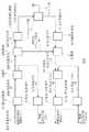
図1は本発明の無線基地局システムの一つの実施の形態を示すブロック図である。
【0026】
図1に示す本実施の形態は、遠方の無線送受信部101と通信接続される無線基地局装置1と、無線送受信部101に通信接続される無線送受信部102と、無線送受信部102に通信接続され以降の無線送受信部は同様にカスケード接続される無線送受信部10Nとから構成されている。
【0027】
図2は図1の無線基地局装置の一例を示す詳細ブロック図である。
【0028】
図2を参照すると無線基地局装置1は、遠方の無線送受信部への送信合成信号21を出力し、かつ遠方の無線送受信部からの受信合成信号71を入力しデータ処理を行うデータ処理部201と、無線送受信部への送信合成信号22を出力し、かつ無線送受信部からの受信合成信号72を入力しデータの処理を行うデータ処理部202と、同様に各無線送受信部への送信合成信号2Nを出力し、かつ受信合成信号7Nを入力しデータの処理を行うデータ処理部20Nと、データ処理部201,202,20Nからの送信合成信号21,22,2Nを入力してそれぞれ拡散処理を行う拡散部2と、拡散部2から出力される送信合成信号31,32,3Nを入力し、これらを多重して送信多重信号41を出力する多重部3と、多重部3から出力された送信多重信号41の電気信号を光信号に変換して、無線送受信部101に送信多重化信号42として出力する電気/光変換部4と、無線送受信部101からの受信多重化信号43を入力して、この光信号を電気信号に変換し受信多重信号44として出力する光/電気変換部5と、光/電気変換部5から出力された受信多重信号44を入力して逆拡散し、受信合成信号71,72,7Nに分離出力する逆拡散部6と、拡散部2から送信合成信号31,32,3Nの拡散タイミング信号81及び逆拡散部6から受信合成信号71,72,7Nの逆拡散タイミング信号82を入力し、送受信信号の遅延時間を測定する遅延測定部7とから構成されている。
【0029】
図3は図1の無線送受信部の一例を示す詳細なブロック図である。
【0030】
図3を参照すると、無線基地局装置1から出力された送信多重化信号42を入力し、光信号を電気信号に変換する光/電気変換部8と、光/電気変換部8が出力した送信多重信号45を入力し、この送信多重信号45を2分配して送信多重信号46および送信多重信号47を出力する分離部9と、分離部9が出力した一方の送信多重信号46の電気信号を光信号に変換し無線送受信部102に出力する電気/光変換部10と、分離部9が出力した他方の送信多重信号47を入力し、逆拡散により必要な送信合成信号48のみ抽出して出力し、かつ逆拡散タイミング信号49を出力する逆拡散部11と、逆拡散部11が出力した送信合成信号48を入力して、送信ベ−スバンド信号と制御信号を分離し、送信ベースバンド信号をデジタル・アナログ変換及び周波数変換し、送信無線信号51として出力する送信無線処理部12と、送信無線処理部12から出力された送信無線信号51を入力し出力するサーキュレータ部13と、サーキュレータ部13から出力された送信無線信号を外部へ送信し、かつ外部からの受信無線信号を受信するアンテナ部14と、アンテナ部14およびサーキュレータ部13からの受信無線信号52を周波数変換およびアナログ・デジタル変換した受信ベースバンド信号を生成し、この受信ベースバンド信号と制御信号を合成することで、受信合成信号53を出力する受信無線処理部15と、この受信無線処理部15が出力した受信合成信号53と逆拡散部11から出力された逆拡散タイミング信号49を入力し、拡散処理を行い受信合成信号54を出力する拡散部16と、無線送受信部102からの光信号を電気信号に変換し受信多重化信号55として出力する光/電気変換部17と、拡散部16が出力した受信合成信号54および光/電気変換部17が出力した受信多重化信号55を多重化し受信多重化信号56として出力する多重部18と、多重部18が出力した受信多重化信号56の電気信号を光信号に変換し無線基地局装置1に出力する電気/光変換部19とから構成されている。
【0031】
なお、無線送受信部102及び他の各無線送受信部の構成も無線送受信部101と同様の構成である。
【0032】
次に本発明の実施の形態について図1を参照して詳細に説明する。
【0033】
ここでは特に、移動通信で使用されているW−CDMA(Wideband−Code Division Multiple Access)方式の無線基地局装置(チップレート3.84Mbps)に対して説明する。
【0034】
また、無線基地局装置1と各無線送受信部間及び無線送受信部と他の無線送受信部との間は、長距離伝送に適した光ファイバを使用して光シリアル伝送させるものとする。さらに無線基地局装置1は、送受信各一本の光ファイバで8つの無線送受信部が接続されており、無線基地局装置1から最も遠距離にある無線送受信部10Nまでの送受信を含めた光ファイバの最大遅延時間を0.8msである場合を例として説明する。
【0035】
従って、無線基地局装置1は図2の構成に加えて図示はしないが、上位装置とのインタフェースを行なう上位インタフェース部と、誤り訂正符号/復号部と、フレーム化部と、データ変調/復調部と、W−CDMA方式としての拡散/逆拡散を行なうベースバンド信号処理部と、上位インタフェース部とベースバンド信号処理部を制御する制御部と、無線送受信部101とのインタフェースを行なう光インタフェース部とが含まれる。
【0036】
一方無線送受信部101〜10Nは図3の構成に加えて図示はしないが、無線基地局装置1及び他の無線送受信部101〜10Nとのインタフェースを行なう光インタフェース部と、ベースバンド信号/無線周波数信号の変換を行ない端末装置とのインタフェースを行なう無線部と、無線部を制御する制御部とが含まれている。
【0037】
次に、図2および図3を参照して送信信号の流れについて説明する。
【0038】
無線基地局装置1のデータ処理部201は、無線送受信部101に出力される送信ベースバンド信号と送信制御信号を時分割多重した送信合成信号21を拡散部2に出力する。データ処理部202〜20Nも同様に、無線送受信部102〜10Nに出力される送信ベースバンド信号と送信制御信号をそれぞれ時分割多重した送信合成信号22および送信合成信号2Nを拡散部2に出力する。
【0039】
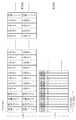
図4はベースバンド信号及び送信制御信号の多重方法の一例を示す図である。
【0040】
ここで送信ベースバンド信号と送信制御信号の多重方法の一例を図4を用いて説明する。
【0041】
まず1単位をフレームとし、フレームの先頭に同期コードを付加する。同期コードは、送信するベースバンド信号と送信する制御信号のデータ位置を検出するために使用される。同期コードの次の時間には制御信号を付加する。制御信号は、無線送受信部の各種の設定や状態監視を行なうために使用される。
【0042】
また、制御信号の次の時間にはベースバンド信号を付加する。ベースバンド信号は、送信ダイバーシチ有の場合、0系/1系からなり、それぞれI/Qの振幅データ情報で構成されている。W−CDMAシステムで要求されるダイナミックレンジや電力制御精度の確保のため、通常それぞれ1byte(8bit)以上のbyte数が必要になる。ここでは、それぞれ0系/1系、I/Qの振幅それぞれに2byteを割り当てる。すなわち1グループとしては8byteの情報が必要である。なお、実際のデータの挿入は光インタフェース間の多重によるダイナミックレンジを考慮する。8多重を考えた場合は、2Byte(16bit)あたり13bit程度とすることにより、
13bit×8<16bit
となるので、多重データをオーバーフローさせることなく伝送できる。
【0043】
以上のことから、送信ベースバンド信号を伝送するのに必要とされる伝送レートは、
3.84Mbps×(8×8)bit=245.76Mbps
となる。なお、送信するベースバンド信号は振幅データのため、連続送信が必要であり、送信合成信号の伝送速度は送信するベースバンド信号の伝送速度と公約数が存在する必要がある。
【0044】
また、送信するベースバンド信号は制御信号と比較してデータ量が大きいため、1フレームあたり同期コード2byte、送信制御信号6byte、送信ベースバンド信号512byteというように割り当てる(合計520byte)。
この場合、送信合成信号を伝送するのに必要とされる伝送レートは、
245.76Mbps×(520/512)=249.6Mbps
となる。次に拡散部2に入力されたデータ処理部201〜20Nを出力した8つの送信合成信号は、それぞれに2種類の拡散コードを割り当てて拡散させる。拡散率は8つの送信合成信号31,32,3Nを合成するため「8」とする。
【0045】
図5は拡散部及び逆拡散部で使用する拡散コードの一例を示す図である。
【0046】
第一の拡散コードは、図5に示されている8つのコードを別々に割り当てる。
理由は、受信側で8つの送信合成信号31,32,3Nを分離するためである。第二の拡散コードは自己相関性の高い最長符号系列(M系列)等により周期的なコードとし、送受信含めた光ファイバの遅延時間よりも長い周期のコードを使用する。ここでは1msと仮定する。
【0047】
第二の拡散コードは8つの送信合成信号31,32,3Nに同じ符号を割り当ててもよいが、同時刻に同パターンの符号系列を割り当てると多重した場合に相互相関性が悪化するため、それぞれの時間をオフセットさせるとよい。この第二のコードは遅延時間を測定するために利用される。
【0048】
なお、拡散後の送信合成信号を伝送するのに必要とされる伝送レートは、拡散率が8のために8倍に拡散されて、
249.6Mbps×8倍=1.9968Gbps
となる。その後、拡散された送信合成信号31,32,3Nは、多重部3に出力される。
【0049】
図6は伝送フォーマットを拡散した場合の一例を示す図である。
【0050】
なお、図6は拡散した後のデータを示した図であり、本例の場合は2byte単位に拡散した場合の例である。8つの送信合成信号31,32,3Nを拡散するため、拡散前は1/15.6MHzであった伝送速度が、拡散後は1/124.8MHz(8倍)となる。
【0051】
次に、多重部3に入力された8つの送信合成信号31,32,3Nは多重され、送信多重信号41として電気/光変換部4に出力される。多重方法はCDMA方式を用いコード多重させることにより、伝送レートは変わらずに多重される。
【0052】
電気/光変換部4に入力される送信多重信号41は、パラレルデータをシリアルデータに変換した後、電気から光信号に変換される。光信号に変換された送信多重化信号42は、光ファイバを経由して無線送受信部101に出力される。
【0053】
また、光ファイバの伝送は通常8B/10Bエンコード/デコードにより、8/10bitに変換して、10bitのシリアル伝送を行なう。
従って、光ファイバを伝送するのに必要とされる伝送レートは、
1.9968Gbps×10/8=2.496Gbps
となる。
【0054】
次に、無線基地局装置1が出力した送信多重化信号42は、図3の無線送受信部101の光/電気変換部8に入力される。ここで送信多重化信号42は光信号から電気信号に変換された後、シリアルデータからパラレルデータに変換され、分離部9に出力される。通常のデシリアライザ(パラレルデータからシリアルデータに変換)は送信側のシリアルデータに同期したクロックを抽出できるため、このクロックを無線送受信部101の基準クロックとすることにより、無線基地局装置1と無線送受信部101とは周波数同期をとることができる。
【0055】
分離部9に入力されたパラレルデータに変換された送信多重信号45は、無線基地局装置1の基準クロックから無線送受信部101の基準クロックに変換するためにリタイミングされた後、一方は電気/光変換部10に出力され、他方は逆拡散部11に出力される。電気/光変換部10に入力された一方の送信多重信号46は、パラレルデータからシリアルデータに変換された後光信号に変換され、無線送受信部102へ出力される。逆拡散部11に入力された他方の送信多重信号47は逆拡散され、必要な送信合成信号のみが抽出され送信合成信号48として送信無線処理部12に出力される。
【0056】
なお、具体的にはまず第二の拡散コードにより逆拡散させ、その後予め各無線送受信部とコード番号の関係を決めておく。このことにより、データ処理部201で生成された送信合成信号21が図5のコード1(第一の拡散コード)で拡散されていた場合は、コード1を用いて逆拡散することによりデータ処理部201で生成された送信合成信号21のみを抽出することが可能である。また、第二の拡散コードの先頭(1ms周期の先頭)を逆拡散により算出し、タイミング信号として拡散部16に出力される。送信無線処理部12に入力された送信合成信号48は、同期コードを使用し送信制御信号と送信ベースバンド信号を分離する。
【0057】
次に、送信ベースバンド信号は、デジタル/アナログ変換および周波数変換がされ、送信無線信号51としてサーキュレータ部13に出力される。また、送信制御信号により、各種設定や状態監視を行なう。
【0058】
サーキュレータ部13に入力された送信無線信号51は、アンテナ部14に出力されるが、受信無線処理部15には出力されない。アンテナ部14に入力された送信無線信号は、外部端末装置へ送信される。
【0059】
なお、図1の無線送受信部102〜10Nの動作も、それぞれ無線送受信部101〜10Nから出力された送信多重信号を入力として、無線送受信部101と同様の動作をする。
【0060】
次に、受信信号の流れについて説明する。
【0061】
外部の端末装置から送信された無線信号は、図3のアンテナ部14に入力される。アンテナ部14に入力された無線信号は、サーキュレータ部13に出力される。サーキュレータ部13に入力された無線信号は、受信無線処理部15に受信無線信号52として出力されるが、送信無線処理部12には出力されない。受信無線処理部15に入力された受信無線信号52は、周波数変換され、アナログ/デジタル変換され、受信ベースバンド信号となる。
【0062】
また、無線基地局装置1への各種の設定応答や状態監視応答を行なう受信制御信号を生成する。その後、受信制御信号と、受信ベースバンド信号の合成を行なう。合成方法は送信側と同様に、同期コードを付加し、受信合成信号53を生成し、拡散部16に出力される。拡散部16に入力された受信合成信号53は、無線送受信部101と同様に2種類の拡散コードを割り当て拡散させる。
【0063】
第一の拡散コードは、図5のコード1を割り当てる。次に、第二の拡散コードは、逆拡散部11から出力された逆拡散タイミング信号82の位置を拡散コードの先頭(1ms周期の先頭)として拡散させる。
【0064】
拡散後のデータは送信側と同様に図6に示すように、拡散前は1/15.6MHzであった伝送速度が拡散後は1/124.8MHz(8倍)となる。その後拡散部16で、拡散された受信合成信号54は、多重部18に出力される。
一方、無線送受信部102からの受信信号は、光/電気変換部17に入力され光から電気信号に変換された後、シリアルデータからパラレルデータに変換され、受信多重化信号55として多重部18に出力される。拡散部16が出力した受信合成信号54と光/電気変換部17が出力した受信多重化信号55は、多重部18で多重化され、受信多重信号56として電気/光変換部19に出力される。
【0065】
なお、多重方法はCDMA方式を用いコード多重させることにより、伝送レートは変わらずに多重化される。電気/光変換部19に入力された受信多重化信号56は、パラレルデータをシリアルデータに変換した後、電気から光信号に変換される。光信号に変換された受信多重化信号56は、光ファイバを経由して無線基地局装置1に出力される。なお、無線送受信部102〜10Nの動作も、それぞれ無線送受信部102〜10Nから出力された受信多重信号を入力として、無線送受信部101と同様の動作をする。
【0066】
次に、無線送受信部102からの受信多重化信号43は、図2の光/電気変換部5に入力される。ここで受信多重化信号43は光から電気信号に変換された後、シリアルデータからパラレルデータに変換され逆拡散部6に出力される。逆拡散部6に入力された受信多重信号44は逆拡散され、8つの受信合成信号71,72,7Nが抽出され、それぞれのデータ処理部201〜20Nに出力される。
【0067】
なお、具体的にはまず第二の拡散コードにより逆拡散させる。その後それぞれの無線送受信部101〜10Nで生成された受信合成信号71,72,7Nは、図5のコード1〜8(第一の拡散コード)で拡散されているため、コード1〜8を用いて逆拡散することにより、それぞれの無線送受信部101〜10Nで生成された受信合成信号71,72,7Nを抽出することが可能である。また、第二の拡散コードの先頭(1ms周期の先頭)を逆拡散により算出し、逆拡散タイミング信号82として遅延測定部7に出力される。それぞれのデータ処理部201〜20Nに入力された受信合成信号71,72,7Nは、受信ベースバンド信号と受信制御信号に分離される。受信ベースバンド信号は、ベースバンド信号処理部(図示せず)に出力される。また、受信制御信号は、無線送受信部101〜10Nの各種設定応答や監視応答を処理する。
【0068】
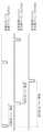
図7は遅延測定部の遅延時間測定のタイムチャートを示す図である。
【0069】
また、拡散部2から拡散タイミング信号81と、逆拡散部6から逆拡散タイミング信号82を入力した遅延測定部7は、図7に示すように、それぞれの無線送受信部101〜10Nに送信した第二の拡散コードの先頭(1ms周期の先頭)と、それぞれの無線送受信部101〜10Nから受信した第二の拡散コードの先頭(1ms周期の先頭)との差から送受信光ファイバ遅延を算出でき、この送受信光ファイバ遅延を1/2とすることにより、無線基地局装置1とそれぞれの無線送受信部101〜10Nの遅延時間を算出することができる。このときの遅延時間の精度は図6に示す拡散単位により、この例の場合は、1/124.8MHz(約3/100chip)の精度を得ることができる。
【0070】
また、運用中に遅延時間を測定したい場合にも、制御信号及びベースバンド信号内に遅延時間測定のためのデータを挿入する必要がないため、システムを通常運用させながら測定が可能となる。
【0071】
図8は伝送フォーマットを拡散した場合の他の一例を示す図である。
【0072】
本発明の他の実施例として、図8に示すように、8つの無線送受信部が接続された状態で、8bit毎に拡散させた場合は、1/249.6MHz(約4/1000chip)の精度を得ることができる。
【0073】
上述の通り、送受信アンテナが複数個遠方にある無線基地局システムにおいて、無線基地局装置と送受信アンテナ間の伝送信号をデジタル信号とし、送信側で複数の送受信アンテナのデジタル信号をCDMA方式により多重し、受信側で複数の送受信アンテナのデジタル信号を分離することにより、既存のサービスを停止することなく無線基地局装置と送受信アンテナ間の遅延時間を高精度に測定できることになる。
【0074】
【発明の効果】
以上説明したように、本発明の無線基地局システムは、無線基地局装置と送受信アンテナ間の遅延時間を高精度で測定でき、かつ運用中に遅延時間の測定ができるので、経年変化等で遅延量が変化した場合にもサービスを停止させることなく遅延時間が測定できる無線基地局システムを供給できるという効果を有している。
【図面の簡単な説明】
【図1】本発明の無線基地局システムの一つの実施の形態を示すブロック図である。
【図2】図1の無線基地局装置の一例を示す詳細ブロック図である。
【図3】図1の無線送受信部の一例を示す詳細ブロック図である。
【図4】ベースバンド信号及び送信制御信号の多重方法の一例を示す図である。
【図5】拡散部及び逆拡散部で使用する拡散コードの一例を示す図である。
【図6】伝送フォーマットを拡散した場合の一例を示す図である。
【図7】遅延測定部の遅延時間測定のタイムチャートを示す図である。
【図8】伝送フォーマットを拡散した場合の他の一例を示す図である。
【図9】従来の時分割方式での伝送フォーマットを示す図である。
【符号の説明】
1 無線基地局装置
2 拡散部
3 多重部
4 電気/光変換部
5 光/電気変換部
6 逆拡散部
7 遅延測定部
8 光/電気変換部
9 分離部
10 電気/光変換部
11 逆拡散部
12 送信無線処理部
13 サーキュレータ部
14 アンテナ部
15 受信無線処理部
16 拡散部
17 光/電気変換部
18 多重部
19 電気/光変換部
21,22,2N 送信合成信号
31,32,3N 送信合成信号
41 送信多重信号
42 送信多重化信号
43 受信多重化信号
44 受信多重信号
45,46,47 送信多重信号
48 送信合成信号
49 逆拡散タイミング信号
51 送信無線信号
52 受信無線信号
53,54 受信合成信号
55,56 受信多重化信号
71,72,7N 受信合成信号
81 拡散タイミング信号
82 逆拡散タイミング信号
101,102,10N 無線送受信部
201,202,20N データ処理部[0001]
BACKGROUND OF THE INVENTION
The present invention relates to a radio base station system, and in particular, a transmission signal between a radio base station apparatus and a remote radio transmission / reception unit is multiplexed by a CDMA system, and the radio base station apparatus and a remote radio transmission / reception unit without stopping an existing service. It is related with the radio base station system which can measure delay time with high precision.
[0002]
[Prior art]
In general, in a radio base station system in which a plurality of transmission / reception antennas are located far away, signals from each transmission / reception antenna are multiplexed by a time division multiplexing method.
[0003]
FIG. 9 is a diagram showing a transmission format in the conventional time division method.
[0004]
When trying to measure the delay time by such a time division method, for example, in a system that supports transmission / reception antennas for eight
[0005]
In this example, when all the data for the transmitting and receiving
[0006]
In the adjustment of the delay time, the delay time is measured using a delay time measuring device, and the variable delay time request is adjusted based on the measurement result.
[0007]
An object of the present invention is to provide a transmission signal between a radio base station apparatus and a remote radio transmission / reception unit transmission / reception antenna as a digital signal in a radio base station system having a plurality of transmission / reception antennas at a distance, and a plurality of transmission / reception antennas on a transmission side. Multiplexing digital signals by CDMA (Code Division Multiple Access) method and separating digital signals from multiple transmission / reception antennas on the receiving side to transmit / receive radio transmission / reception units far away from the radio base station apparatus without stopping existing services A radio base station system that can measure the delay time between antennas with high accuracy can be provided.
[0008]
The conventional radio base station system time-division-multiplexes the signals of each element of the variable directivity antenna of the base station with a time-division multiplexing device, and transmits the time-division-multiplexed signals through the same optical fiber. The relative position difference between the elements is eliminated and the relative phase difference between the elements of the antenna is maintained (for example, see Patent Document 1).
[0009]
In addition, a transmission / reception device is installed in the central base station, a transmission / reception antenna is installed in the radio base station, the radio base station and the central base station are connected by a transmission line, and a signal is transmitted between the transmission / reception device and the transmission / reception antenna. For example, there is a base station apparatus including a full-duplex inter-base station transmission line and a state that monitors the state of the transmission line (see, for example, Patent Document 2).
[0010]
[Patent Document 1]
JP 2001-94332 A (page 3-5, FIG. 1 and FIG. 2)
[Patent Document 2]
Japanese Patent Laid-Open No. 5-327632 (page 2-3, FIG. 1)
[0011]
[Problems to be solved by the invention]
In the conventional radio base station system described above, when the delay time is to be measured by such a time division method, the time allocated to each transmission / reception antenna is 1/8 of the total time, and thus the unit of 1/8 However, there is a drawback that there is only a measurement accuracy of the delay amount.
[0012]
In addition, when all the data for the transmitting and receiving
[0013]
An object of the present invention is a wireless base station system in which a plurality of wireless transmission / reception units having transmission / reception antennas are located far away, wherein a transmission signal between the transmission / reception antennas of the wireless base station device and the wireless transmission / reception unit is a digital signal, and a plurality of transmission signals are transmitted on the transmission side. Multiplexing the digital signals of the transmitting and receiving antennas by the CDMA method, and separating the digital signals of the plurality of transmitting and receiving antennas on the receiving side, without stopping the existing service, between the radio base station apparatus and the remote radio transmitting and receiving unit transmitting and receiving antennas And providing a radio base station system capable of measuring the delay time with high accuracy.
[0014]
[Means for Solving the Problems]
The first radio base station system of the present invention is:A radio base station system comprising: a radio base station apparatus; and a plurality of radio transmission / reception units in which signal transmission / reception paths are connected in cascade with the radio base station apparatus, wherein the radio base station apparatus transmits to the radio transmission / reception unit Each transmission signal to be transmitted is spread with a first spreading code for identifying the radio transmission / reception unit and a second spreading code used for delay time measurement, and the spread signal is multiplexed by a CDMA system to be a transmission multiplexed signal. As a reception signal received from the wireless transmission / reception unit, a transmission processing unit that outputs the received multiplexed signal received from the wireless transmission / reception unit is despread with the first spreading code and the second spreading code. A reception processing means for outputting, a spreading timing signal obtained by spreading processing using the second spreading code by the transmission processing means, and the second by the receiving processing means. Delay measurement means for inputting a despread timing signal obtained by a despreading process using a spread code and obtaining a delay time of the transmission / reception signal, wherein the radio transmission / reception unit is a transmission multiplex that the radio base station apparatus outputs Separating means for separating the multiplex signal into a first transmission multiplex signal to be output to another radio transmission / reception unit connected in cascade and a second transmission multiplex signal to be processed by the own radio transmission / reception unit; The transmission multiplexed signal is despread with a first spreading code for identifying the own radio transmitting / receiving unit and a second spreading code used for delay time measurement, and the transmission signal corresponding to the own radio transmitting / receiving unit is passed through the antenna unit. And the second transmission processing means for outputting the received signal received via the antenna unit by the second transmission processing means using the first spreading code and the second spreading code. Inverse with spreading code Receiving means for spreading and outputting at the start timing obtained by the spreading process; a spread signal inputted from the receiving means; and a first received multiplexed signal inputted from another radio transmission / reception unit connected to the cascade; Multiplexing means for multiplexing the signal and outputting it as a second received multiplexed signal.
[0015]
The second radio base station system of the present invention isEach transmission signal to be transmitted to a plurality of wireless transmission / reception units connected in cascade to the signal transmission / reception path is spread with a first spreading code for identifying the wireless transmission / reception unit and a second spreading code used for delay time measurement, The spread transmission signals are multiplexed by a CDMA system and output to the wireless transmission / reception unit as a transmission multiplexed signal, and the reception multiplexed signal input from the wireless transmission / reception unit is converted to the first spreading code and the second A radio base station apparatus that despreads with a spreading code and generates each received signal received from the plurality of radio transmission / reception units, the transmission multiplexed signal is input, the first spreading code and the second spreading A transmission signal extracted by despreading with a code is output via an antenna unit, and the signal received via the antenna unit is transmitted using the first spreading code and the second spreading code. A radio transmission / reception unit that generates a spread reception signal spread at the despreading timing of the second spreading code used in signal despreading and outputs it as a reception multiplexed signal, and the radio transmission / reception unit is cascade-connected. A radio transmission / reception unit different from the radio transmission / reception unit that outputs the reception multiplexed signal by multiplexing the reception multiplexed signal output by the radio transmission / reception unit and the spread reception signal generated by the radio transmission / reception unit. And the radio base station apparatus has a delay measurement unit that obtains a delay time of the transmission / reception signal based on a spreading timing of the transmission signal of the second spreading code and a despreading timing of the received multiplexed signal It is characterized by that.
[0016]
The third radio base station system of the present invention isEach transmission signal to be transmitted to a plurality of wireless transmission / reception units connected in cascade to the signal transmission / reception path is spread with a first spreading code for identifying the wireless transmission / reception unit and a second spreading code used for delay time measurement, Transmission processing means for multiplexing each spread transmission signal by a CDMA method and outputting it as a transmission multiplexed signal, and the received multiplexed signal input from the radio transmission / reception unit, the first transmission / reception unit identifying the radio transmission / reception unit A radio base station apparatus comprising: a reception processing means that performs despreading with a spreading code and the second spreading code used for delay time measurement and outputs each received signal received from the plurality of radio transmitting and receiving units; and A second transmission process for inputting a transmission multiplexed signal output from the base station apparatus and outputting a transmission signal despread by the first spreading code and the second spreading code via an antenna unit And the received signal received via the antenna unit at the despreading timing of the second spreading code by the second transmission processing means using the first spreading code and the second spreading code. A wireless transmission / reception unit including a second reception processing unit that generates a spread spread reception signal, multiplexes and outputs it as a reception multiplexed signal, and the wireless transmission / reception unit includes other wireless units connected in cascade. A radio transmission / reception unit or a radio base station apparatus different from the radio transmission / reception unit that multiplexes the reception multiplexed signal output by the transmission / reception unit and the spread reception signal generated by the own radio transmission / reception unit and outputs the reception multiplexed signal The radio base station apparatus outputs the spreading timing of the second spreading code by the transmission processing means and the despreading timing of the second spreading code by the reception processing means. Characterized in that it has a delay measurement means for obtaining a delay time of the reception signal based on and.
[0017]
The fourth radio base station system of the present invention isA radio base station system having a radio base station apparatus and a plurality of radio transmission / reception units having signal transmission / reception paths connected in cascade with the radio base station apparatus, wherein the radio base station apparatus includes the plurality of radio transmission / reception units The first transmission composite signal to be transmitted to is spread with a different first spreading code for each wireless transmission / reception unit, and the signal spread with the first spreading code is spread with the second spreading code to obtain a plurality of second transmissions. A spread signal that outputs a combined signal and outputs the start timing of the second spread code as a spread timing signal, and the plurality of second transmission combined signals that are output from the spread unit are input, and these are transmitted by CDMA A multiplexing section for multiplexing and outputting a transmission multiplexed signal; means for outputting the transmission multiplexed signal output from the multiplexing section to the wireless transmission / reception section as a transmission multiplexed signal; The received multiplexed signal is despread with the second spreading code, the signal despread with the second spreading code is despread with the first spreading code and separated into a plurality of received composite signals, and the second spreading is performed. A despreading unit that outputs the start timing of the code as a despreading timing signal, a spreading timing signal output from the spreading unit, and a delay time of the transmission / reception signal based on the despreading timing signal output from the despreading unit Delay measurement means, wherein the radio transmission / reception unit inputs the transmission multiplexed signal received from the radio base station apparatus, distributes the transmission multiplexed signal into two, and transmits the first transmission multiplexed signal and the first transmission multiplexed signal. A separation unit that outputs two transmission multiplexed signals, means for outputting the first transmission multiplexed signal output from the separation unit to another cascaded wireless transmission / reception unit, and before the output from the separation unit The second transmission multiplexed signal is input, despread by the second spreading code, the despread signal is despread by the first spreading code corresponding to the own radio transmitting / receiving unit, and addressed to the own radio transmitting / receiving unit. A transmission composite signal is extracted, and a second despreading unit that outputs the start timing of the second spreading code as a second despreading timing signal, and the transmission composite signal output by the second despreading unit are input. Then, the transmission baseband signal and the control signal are separated, the transmission baseband signal is transmitted to the outside, the antenna unit that receives the external radio signal, and the reception baseband from the reception radio signal from the antenna unit By generating a signal and combining the reception baseband signal and the control signal, a reception radio processing unit that outputs a first reception combination signal, and a first reception combination signal output by the reception radio processing unit Own radio Spread by the first spreading code corresponding to the transmission / reception unit, and the spread signal is output from the second despreading unit to the second despreading timing signal as the head of the spreading code. A second spreading section that performs spreading processing using a spreading code and outputs a second received composite signal; a first received multiplexed signal received from another cascaded wireless transceiver section; and the spreading section outputs And a second multiplexing unit that multiplexes the second received combined signal and outputs it as a received multiplexed signal.
[0018]
The fifth radio base station system of the present invention isIn any one of the first to fourth radio base station systems, the second spreading code is a periodic code of a code sequence having high autocorrelation, and is longer than a delay time including transmission / reception in the signal transmission / reception path. Characterized by having a long period
[0019]
The sixth radio base station system of the present invention isIn the radio base station system according to any one of the first to fifth aspects, when the same code is used as the second spreading code corresponding to a plurality of radio transmitting / receiving units, the time difference offset at the time of spreading in the radio base station device It is characterized in that the diffusion is performed at the diffusion timing.
[0020]
The seventh radio base station system of the present invention isIn any one of the first to sixth radio base station systems, the delay measurement unit included in the radio base station device inputs the spread timing signal and the despread timing signal, and inputs each of the plurality of radio transmission / reception units. A delay in a signal transmission / reception path is calculated from a difference between the head of the transmitted spreading code and the head of the spreading code received from each of the plurality of radio transmission / reception units, and the radio base station apparatus and the plurality of radio transmission / reception units Each delay time is calculated.
[0021]
Of the present inventionThe radio base station apparatus uses each transmission signal to be transmitted to a plurality of radio transmission / reception units whose signal transmission / reception paths are connected in cascade, for the first spreading code for identifying the radio transmission unit and the second time used for measuring the delay time. A transmission processing means for spreading with a spreading code, multiplexing each spread transmission signal by a CDMA system and outputting it as a transmission multiplexed signal, and a received multiplexed signal input from the wireless transmission / reception unit, the first spreading code And the second spreading code are despread and output as each received signal received from the plurality of radio transmitting and receiving units, the spreading timing of the second spreading code by the transmission processing means, Delay measuring means for obtaining a delay time of the transmission / reception signal from the despreading timing of the second spreading code by the reception processing means, and the received multiplexed signal is the wireless transmission signal. The transmission unit includes a spread signal obtained by spreading the received signal with the first spread code and the second spread code at the despread timing of the second spread code used for despreading the transmission multiplexed signal. It is characterized by that.
[0022]
In addition, the present inventionThe radio base station apparatus spreads a first transmission composite signal to be transmitted to a plurality of cascaded radio transmission / reception units using a first spreading code that is different for each radio transmission / reception unit, and spreads the signal spread by the first spreading code. A spreading unit that spreads with the second code and outputs a plurality of second transmission composite signals, and outputs the leading timing of the second spreading code as a spreading timing signal, and the plurality of second signals output from the spreading unit The transmission composite signal is input and multiplexed by the CDMA method to output a transmission multiplexed signal, and the transmission multiplexed signal output from the multiplexing unit is output to the wireless transmission / reception unit as a transmission multiplexed signal Means for receiving the transmission multiplexed signal, wherein the start timing of the second spreading code is second from the transmission multiplexed signal separated from the transmission multiplexed signal. A signal output as a despread timing signal and received by the antenna unit is spread by a first spreading code corresponding to the own radio transmitting / receiving unit, and the spread signal starts from the position of the second despread timing signal. As the second despreading code is subjected to spreading processing and output, and the signal output from the wireless transmission / reception unit is despread with the second spreading code and the signal despread with this second spreading code is A despreading unit that despreads with the first spreading code and separates into a plurality of received composite signals, and outputs the start timing of the second spreading code as a despreading timing signal; and a spreading timing signal output from the spreading unit; And a delay unit for obtaining a delay time of the transmission / reception signal from the despread timing signal output from the despread unit.
[0023]
Of the present inventionA communication method is a communication method between a radio base station apparatus and a radio transceiver unit connected in cascade with the radio base station, and a radio transmission / reception unit transmits a first transmission composite signal to be transmitted to the radio transceiver unit The first spread code is spread with a different first spread code, the signal spread with the first spread code is spread with the second spread code, a plurality of second transmission composite signals are output, and the start timing of the second spread code Is transmitted as a spreading timing signal, the second transmission composite signal is input, a multiplexing step is performed in which these are multiplexed by a CDMA method, and a transmission multiplexed signal is output, and the transmission multiplexed signal is transmitted to the radio transmission / reception unit A step of outputting as a multiplexed signal, and the transmission multiplexed signal separated from the transmission multiplexed signal is despread by a second spreading code, and the despread signal is corresponded to the radio transmission / reception unit. A second despreading step for despreading with the first spreading code, extracting a transmission composite signal addressed to the radio transmission / reception unit, and outputting the start timing of the second spreading code as a second despreading timing signal; A step of transmitting a composite signal to the outside and receiving a signal from the outside; and spreading the received signal with a first spreading code corresponding to a wireless transmission / reception unit; and spreading the spread signal to the second despreading timing A second spreading step for performing a spreading process with the second spreading code with the signal position as the head of the spreading code and outputting a received synthesized signal; and despreading the received synthesized signal with the second spreading code. The signal despread with the second spreading code is despread with the first spreading code and separated into a plurality of second received composite signals, and the leading timing of the second spreading code is used as the despreading timing signal. Despreading step of outputting, and having a delay measuring step of determining the spreading timing signal and the despreading timing signal and the delay time of the transmission and reception signals from.
[0024]
DETAILED DESCRIPTION OF THE INVENTION
Next, embodiments of the present invention will be described with reference to the drawings.
[0025]
FIG. 1 is a block diagram showing an embodiment of a radio base station system of the present invention.
[0026]
In the present embodiment shown in FIG. 1, a radio
[0027]
FIG. 2 is a detailed block diagram showing an example of the radio base station apparatus of FIG.
[0028]
Referring to FIG. 2, the radio
[0029]
FIG. 3 is a detailed block diagram illustrating an example of the wireless transmission / reception unit of FIG.
[0030]
Referring to FIG. 3, the transmission multiplexed signal 42 output from the radio
[0031]
The configuration of the wireless transmission /
[0032]
Next, an embodiment of the present invention will be described in detail with reference to FIG.
[0033]
Here, a W-CDMA (Wideband-Code Division Multiple Access) type radio base station apparatus (chip rate of 3.84 Mbps) used in mobile communication will be particularly described.
[0034]
Further, optical serial transmission is performed between the wireless
[0035]
Accordingly, the radio
[0036]
On the other hand, the wireless transmission /
[0037]
Next, the flow of the transmission signal will be described with reference to FIG. 2 and FIG.
[0038]
The data processing unit 201 of the radio
[0039]
FIG. 4 is a diagram illustrating an example of a method for multiplexing the baseband signal and the transmission control signal.
[0040]
Here, an example of a method of multiplexing the transmission baseband signal and the transmission control signal will be described with reference to FIG.
[0041]
First, one unit is a frame, and a synchronization code is added to the head of the frame. The synchronization code is used to detect the data position of the baseband signal to be transmitted and the control signal to be transmitted. A control signal is added at the next time of the synchronization code. The control signal is used to perform various settings and state monitoring of the wireless transmission / reception unit.
[0042]
In addition, a baseband signal is added at the next time of the control signal. The baseband signal has 0 system / 1 system in the case of transmission diversity, and is configured by I / Q amplitude data information. In order to ensure the dynamic range and power control accuracy required in the W-CDMA system, it is usually necessary to have 1 byte (8 bits) or more. Here, 2 bytes are assigned to each of the 0-system / 1-system and I / Q amplitudes. That is, 8 bytes of information are required for one group. The actual data insertion takes into account the dynamic range due to multiplexing between optical interfaces. When 8 multiplexing is considered, by setting it to about 13 bits per 2 bytes (16 bits),
13 bits x 8 <16 bits
Therefore, the multiplexed data can be transmitted without overflowing.
[0043]
From the above, the transmission rate required to transmit the transmission baseband signal is
3.84 Mbps × (8 × 8) bit = 245.76 Mbps
It becomes. Since the baseband signal to be transmitted is amplitude data, continuous transmission is necessary, and the transmission rate of the transmission composite signal needs to be the same as the transmission rate of the baseband signal to be transmitted and the common divisor.
[0044]
In addition, since the baseband signal to be transmitted has a larger data amount than the control signal, it is assigned as a
In this case, the transmission rate required to transmit the transmission composite signal is
245.76 Mbps × (520/512) = 249.6 Mbps
It becomes. Next, the eight transmission composite signals output from the data processing units 201 to 20N input to the spreading
[0045]
FIG. 5 is a diagram illustrating an example of a spreading code used in the spreading unit and the despreading unit.
[0046]
The first spreading code assigns the eight codes shown in FIG. 5 separately.
The reason is to separate the eight transmission composite signals 31, 32, 3N on the receiving side. The second spreading code is a periodic code such as a longest code sequence (M sequence) having a high autocorrelation, and a code having a period longer than the delay time of the optical fiber including transmission and reception is used. Here, 1 ms is assumed.
[0047]
The second spreading code may assign the same code to the eight transmission composite signals 31, 32, 3N, but if the code sequence of the same pattern is assigned at the same time, the cross-correlation deteriorates when multiplexed. It is better to offset the time. This second code is used to measure the delay time.
[0048]
Note that the transmission rate required to transmit the spread transmission composite signal is spread by 8 times because the spreading factor is 8,
249.6 Mbps x 8 times = 1.9968 Gbps
It becomes. Thereafter, the spread transmission composite signals 31, 32, 3 N are output to the multiplexing unit 3.
[0049]
FIG. 6 is a diagram showing an example when the transmission format is spread.
[0050]
FIG. 6 is a diagram showing the data after spreading. In this example, the data is spread in units of 2 bytes. Since the eight transmission composite signals 31, 32, and 3N are spread, the transmission rate that was 1 / 15.6 MHz before spreading becomes 1 / 14.8 MHz (8 times) after spreading.
[0051]
Next, the eight transmission composite signals 31, 32, 3N input to the multiplexing unit 3 are multiplexed and output to the electrical / optical conversion unit 4 as a transmission multiplexed signal 41. Multiplexing is performed without changing the transmission rate by code multiplexing using the CDMA method.
[0052]
The transmission multiplexed signal 41 input to the electrical / optical converter 4 converts parallel data into serial data, and then converts from electrical to optical signals. The multiplexed transmission signal 42 converted into an optical signal is output to the wireless transmission /
[0053]
Also, optical fiber transmission is usually converted to 8/10 bits by 8B / 10B encoding / decoding, and 10-bit serial transmission is performed.
Therefore, the transmission rate required to transmit the optical fiber is
1.9968 Gbps x 10/8 = 2.496 Gbps
It becomes.
[0054]
Next, the transmission multiplexed signal 42 output from the radio
[0055]
The transmission multiplexed signal 45 converted into parallel data input to the separation unit 9 is retimed to convert from the reference clock of the radio
[0056]
Specifically, first, despreading is performed using the second spreading code, and then the relationship between each wireless transmission / reception unit and the code number is determined in advance. As a result, when the transmission composite signal 21 generated by the data processing unit 201 is spread by the code 1 (first spreading code) in FIG. 5, the data processing unit is despread using the
[0057]
Next, the transmission baseband signal is subjected to digital / analog conversion and frequency conversion, and is output to the
[0058]
The transmission radio signal 51 input to the
[0059]
Note that the operations of the wireless transmission /
[0060]
Next, the flow of the received signal will be described.
[0061]
A radio signal transmitted from an external terminal device is input to the
[0062]
In addition, a reception control signal for generating various setting responses and state monitoring responses to the radio
[0063]
The first spreading code is assigned
[0064]
As shown in FIG. 6, the data after spreading is 1 / 15.6 MHz before spreading, and becomes 1 / 14.8 MHz (8 times) after spreading, as shown in FIG. Thereafter, the reception
On the other hand, the reception signal from the wireless transmission /
[0065]
The multiplexing method is multiplexed without changing the transmission rate by code multiplexing using the CDMA method. The reception multiplexed signal 56 input to the electrical / optical conversion unit 19 is converted from electrical to optical signals after converting parallel data into serial data. The reception multiplexed signal 56 converted into an optical signal is output to the radio
[0066]
Next, the reception multiplexed signal 43 from the wireless transmission /
[0067]
Specifically, first, despreading is performed using the second spreading code. Thereafter, the received
[0068]
FIG. 7 is a diagram showing a time chart of delay time measurement of the delay measurement unit.
[0069]
Further, the delay measuring unit 7 that has received the spreading timing signal 81 from the spreading
[0070]
Further, when it is desired to measure the delay time during operation, it is not necessary to insert data for delay time measurement into the control signal and the baseband signal, so that the measurement can be performed while the system is normally operated.
[0071]
FIG. 8 is a diagram showing another example when the transmission format is spread.
[0072]
As another embodiment of the present invention, as shown in FIG. 8, accuracy is 1 / 249.6 MHz (about 4/1000 chips) when spread every 8 bits in a state where 8 wireless transmission / reception units are connected. Can be obtained.
[0073]
As described above, in a radio base station system in which a plurality of transmission / reception antennas are far away, a transmission signal between the radio base station apparatus and the transmission / reception antenna is a digital signal, and a digital signal of the plurality of transmission / reception antennas is multiplexed by a CDMA method on the transmission side. By separating digital signals from a plurality of transmission / reception antennas on the receiving side, the delay time between the radio base station apparatus and the transmission / reception antenna can be measured with high accuracy without stopping existing services.
[0074]
【The invention's effect】
As described above, the radio base station system of the present invention can measure the delay time between the radio base station apparatus and the transmission / reception antenna with high accuracy and can measure the delay time during operation. Even when the amount changes, there is an effect that it is possible to supply a radio base station system capable of measuring the delay time without stopping the service.
[Brief description of the drawings]
FIG. 1 is a block diagram showing an embodiment of a radio base station system of the present invention.
2 is a detailed block diagram illustrating an example of a radio base station apparatus in FIG. 1;
3 is a detailed block diagram illustrating an example of a wireless transmission / reception unit in FIG. 1. FIG.
FIG. 4 is a diagram illustrating an example of a method for multiplexing a baseband signal and a transmission control signal.
FIG. 5 is a diagram illustrating an example of a spreading code used in a spreading unit and a despreading unit.
FIG. 6 is a diagram illustrating an example when a transmission format is spread.
FIG. 7 is a diagram illustrating a time chart of delay time measurement of a delay measurement unit.
FIG. 8 is a diagram illustrating another example when the transmission format is spread.
FIG. 9 is a diagram illustrating a transmission format in a conventional time division method.
[Explanation of symbols]
1 Radio base station equipment
2 Diffusion part
3 Multiplexer
4 Electricity / light conversion part
5 Optical / electrical converter
6 Despreading part
7 Delay measurement unit
8 Optical / electrical converter
9 Separation part
10 Electricity / Optical conversion part
11 Despreading part
12 Transmission radio processing part
13 Circulator
14 Antenna section
15 Received radio processor
16 Diffusion part
17 Optical / electrical converter
18 Multiplexer
19 Electricity / light conversion part
21, 22, 2N Transmission composite signal
31, 32, 3N transmission composite signal
41 Transmission multiplexed signal
42 Transmitted multiplexed signal
43 Received multiplexed signal
44 Received multiplexed signal
45, 46, 47 Transmission multiplexed signal
48 Transmission composite signal
49 Despread timing signal
51 Transmitting radio signal
52 Received radio signal
53,54 Received composite signal
55, 56 Receive multiplexed signal
71, 72, 7N Received composite signal
81 Spreading timing signal
82 Despread timing signal
101, 102, 10N Wireless transceiver
201, 202, 20N Data processing unit
Claims (10)
Translated fromJapanese前記無線基地局装置は、 The wireless base station device
前記無線送受信部に送信する各送信信号を、前記無線送受信部を識別する第一の拡散コードと遅延時間測定に用いる第二の拡散コードとで拡散し、この拡散された信号をCDMA方式により多重して送信多重化信号として出力する送信処理手段と、 Each transmission signal transmitted to the wireless transmission / reception unit is spread with a first spreading code for identifying the wireless transmission / reception unit and a second spreading code used for delay time measurement, and the spread signal is multiplexed by a CDMA method. Transmission processing means for outputting as a transmission multiplexed signal,
前記無線送受信部から受信した受信多重化信号を、前記第一の拡散コードと前記第二の拡散コードとで逆拡散し、前記無線送受信部から受信した受信信号として出力する受信処理手段と、 A reception processing means for despreading the reception multiplexed signal received from the wireless transmission / reception unit with the first spreading code and the second spreading code, and outputting the received signal as the reception signal received from the wireless transmission / reception unit;
前記送信処理手段による前記第二の拡散コードを用いた拡散処理により求めた拡散タイミング信号と、前記受信処理手段による前記第二の拡散コードを用いた逆拡散処理により求めた逆拡散タイミング信号とを入力し送受信信号の遅延時間を求める遅延測定手段と、 A spreading timing signal obtained by spreading processing using the second spreading code by the transmission processing means and a despreading timing signal obtained by despreading processing using the second spreading code by the receiving processing means. A delay measuring means for obtaining a delay time of an input and received signal,
を備え、 With
前記無線送受信部は、 The wireless transceiver unit is
前記無線基地局装置が出力する送信多重化信号を、カスケードに接続された他の無線送受信部に出力する第1の送信多重化信号と自無線送受信部で処理する第2の送信多重化信号とに分離する分離手段と、 A transmission multiplexed signal output from the radio base station apparatus, a first transmission multiplexed signal output to another radio transmission / reception unit connected in cascade, and a second transmission multiplexed signal processed by the own radio transmission / reception unit; Separating means for separating into
前記第2の送信多重化信号を、自無線送受信部を識別する第一の拡散コードと遅延時間測定に用いる第二の拡散コードとで逆拡散し、自無線送受信部に対応する送信信号をアンテナ部を介して出力する第2の送信処理手段と、 The second transmission multiplexed signal is despread with a first spreading code for identifying the own radio transmission / reception unit and a second spreading code used for delay time measurement, and the transmission signal corresponding to the own radio transmission / reception unit is transmitted to the antenna. Second transmission processing means for outputting via the unit;
アンテナ部を介して受信した受信信号を、第一の拡散コードと第二の拡散コードとを用いて、前記第2の送信処理手段で前記第二の拡散コードを用いた逆拡散処理により求めた先頭タイミングで拡散して出力する受信手段と、 The received signal received via the antenna unit is obtained by despreading processing using the second spreading code by the second transmission processing means using the first spreading code and the second spreading code. Receiving means for spreading and outputting at the start timing;
前記受信手段から入力する拡散された信号と、カスケードに接続された他の無線送受信部から入力する第1の受信多重化信号とを多重して第2の受信多重化信号として出力する多重手段と A multiplexing unit that multiplexes the spread signal input from the reception unit and the first reception multiplexed signal input from another radio transmission / reception unit connected in cascade and outputs the multiplexed signal as a second reception multiplexed signal;
を備えることを特徴とする無線基地局システム。 A radio base station system comprising:
前記送信多重化信号を入力し、前記第一の拡散コードと前記第二の拡散コードで逆拡散して抽出した送信信号を、アンテナ部を介して出力し、アンテナ部を介して受信した信号を前記第一の拡散コードと前記第二の拡散コードとを用いて、前記送信多重化信号の逆拡散で用いた前記第二の拡散コードの逆拡散タイミングで拡散した拡散受信信号を生成し受信多重化信号として出力する無線送受信部と The transmission multiplexed signal is input, the transmission signal extracted by despreading with the first spreading code and the second spreading code is output via the antenna unit, and the signal received via the antenna unit is output. The first spread code and the second spread code are used to generate a spread received signal spread at the despread timing of the second spread code used in the despreading of the transmission multiplexed signal, and receive multiplexing A wireless transmitter / receiver that outputs as a
を備え、 With
前記無線送受信部は、カスケード接続された無線送受信部が出力する受信多重化信号と無線送受信部で生成した前記拡散受信信号とを多重して、前記受信多重化信号を出力する無線送受信部とは異なる無線送受信部または前記無線基地局装置のいずれかに出力し、 The wireless transmission / reception unit multiplexes the reception multiplexed signal output by the cascaded wireless transmission / reception units and the spread reception signal generated by the wireless transmission / reception unit, and outputs the reception multiplexed signal. Output to either a different radio transceiver unit or the radio base station device,
前記無線基地局装置は、前記第二の拡散コードの送信信号の拡散タイミングと受信多重信号の逆拡散タイミングとに基づいて送受信信号の遅延時間を求める遅延測定手段を有する The radio base station apparatus has delay measurement means for obtaining a delay time of a transmission / reception signal based on a spreading timing of a transmission signal of the second spreading code and a despreading timing of a reception multiplexed signal.
ことを特徴とする無線基地局システム。A radio base station system.
前記無線基地局装置が出力する送信多重化信号を入力し、前記第一の拡散コードと前記第二の拡散コードで逆拡散した送信信号をアンテナ部を介して出力する第2の送信処理手段と、アンテナ部を介して受信した受信信号を、前記第一の拡散コードと前記第二の拡散コードを用いて、前記第2の送信処理手段による前記第二の拡散コードの逆拡散タイミングで拡散した拡散受信信号を生成し、多重して受信多重化信号として出力する第2の受信処理手段を備えた無線送受信部と Second transmission processing means for inputting a transmission multiplexed signal output from the radio base station apparatus and outputting a transmission signal despread by the first spreading code and the second spreading code via an antenna unit; The received signal received via the antenna unit is spread at the despreading timing of the second spreading code by the second transmission processing means using the first spreading code and the second spreading code. A radio transmission / reception unit including a second reception processing unit that generates a spread reception signal, multiplexes and outputs the reception reception multiplexed signal;
を有し、Have
前記無線送受信部は、カスケードに接続された他の無線送受信部が出力する受信多重化信号と自無線送受信部で生成した前記拡散受信信号とを多重して、前記受信多重化信号を出力する無線送受信部とは異なる無線送受信部または前記無線基地局装置のいずれかに出力し、 The radio transmission / reception unit multiplexes a reception multiplexed signal output from another radio transmission / reception unit connected in cascade and the spread reception signal generated by the own radio transmission / reception unit, and outputs the reception multiplexed signal Output to either the radio transceiver unit or the radio base station device different from the transceiver unit,
前記無線基地局装置は、前記送信処理手段による前記第二の拡散コードの拡散タイミングと前記受信処理手段による前記第二の拡散コードの逆拡散タイミングとに基づいて送受信信号の遅延時間を求める遅延測定手段を有することを The radio base station apparatus performs delay measurement for determining a delay time of a transmission / reception signal based on a spreading timing of the second spreading code by the transmission processing unit and a despreading timing of the second spreading code by the reception processing unit Having means
特徴とする無線基地局システム。A wireless base station system that is characterized.
前記無線基地局装置は、 The wireless base station device
前記複数の無線送受信部へ送信する第1の送信合成信号を無線送受信部ごとに異なる第一の拡散コードで拡散しこの第一の拡散コードで拡散された信号を第二の拡散コードで拡散し複数の第2の送信合成信号を出力し、第二の拡散コードの先頭タイミングを拡散タイミング信号として出力する拡散部と、 The first transmission composite signal to be transmitted to the plurality of radio transmission / reception units is spread with a different first spreading code for each radio transmission / reception unit, and the signal spread with the first spreading code is spread with a second spreading code. A spreading unit that outputs a plurality of second transmission composite signals, and outputs the leading timing of the second spreading code as a spreading timing signal;
この拡散部から出力される前記複数の第2の送信合成信号を入力し、これらをCDMA方式により多重して送信多重信号を出力する多重部と、 A multiplexer that inputs the plurality of second transmission composite signals output from the spreading unit, multiplexes them by a CDMA method, and outputs a transmission multiplexed signal;
この多重部から出力された前記送信多重信号を前記無線送受信部に送信多重化信号として出力する手段と、 Means for outputting the transmission multiplexed signal output from the multiplexing unit to the wireless transceiver as a transmission multiplexed signal;
無線送受信部から受信する受信多重化信号を第二の拡散コードで逆拡散しこの第二の拡散コードで逆拡散された信号を第一の拡散コードで逆拡散し複数の受信合成信号に分離し、第二の拡散コードの先頭タイミングを逆拡散タイミング信号として出力する逆拡散部と、 The received multiplexed signal received from the wireless transmitter / receiver is despread with the second spreading code, and the signal despread with the second spreading code is despread with the first spreading code and separated into a plurality of received composite signals. A despreading unit that outputs the start timing of the second spreading code as a despreading timing signal;
前記拡散部から出力された拡散タイミング信号及び前記逆拡散部から出力された逆拡散タイミング信号に基づいて送受信信号の遅延時間を求める遅延測定手段と、 A delay measuring means for obtaining a delay time of a transmission / reception signal based on the spreading timing signal output from the spreading unit and the despreading timing signal output from the despreading unit;
を備え、 With
前記無線送受信部は、 The wireless transceiver unit is
前記無線基地局装置から受信した前記送信多重化信号を入力し、この送信多重化信号を2分配して、第1の送信多重信号及び第2の送信多重信号を出力する分離部と、 A demultiplexer that inputs the transmission multiplexed signal received from the radio base station apparatus, divides the transmission multiplexed signal into two, and outputs a first transmission multiplexed signal and a second transmission multiplexed signal;
この分離部が出力した前記第1の送信多重信号をカスケード接続された他の無線送受信部に出力する手段と、 Means for outputting the first transmission multiplexed signal output by the demultiplexing section to another radio transmitting / receiving section connected in cascade;
前記分離部が出力した前記第2の送信多重信号を入力し、第二の拡散コードにより逆拡散し、この逆拡散された信号を自無線送受信部に対応した第一の拡散コードで逆拡散し、自無線送受信部宛ての送信合成信号を抽出し、第二の拡散コードの先頭タイミングを第2の逆拡散タイミング信号として出力する第2の逆拡散部と、 The second transmission multiplexed signal output from the demultiplexing unit is input, despread by the second spreading code, and the despread signal is despread by the first spreading code corresponding to the own radio transmitting / receiving unit. A second despreading unit that extracts a transmission composite signal addressed to the own radio transmission / reception unit and outputs the start timing of the second spreading code as a second despreading timing signal;
この第2の逆拡散部が出力した前記送信合成信号を入力して、送信ベ−スバンド信号と制御信号とに分離し、送信ベースバンド信号を外部へ送信し、外部からの無線信号を受信するアンテナ部と、 The transmission composite signal output from the second despreading unit is input, separated into a transmission baseband signal and a control signal, a transmission baseband signal is transmitted to the outside, and a radio signal from the outside is received. An antenna section;
このアンテナ部からの受信無線信号から受信ベースバンド信号を生成し、この受信ベースバンド信号と制御信号を合成することで、第1の受信合成信号を出力する受信無線処理部と、 A reception radio processing unit that generates a reception baseband signal from the reception radio signal from the antenna unit and combines the reception baseband signal and the control signal to output a first reception composite signal;
この受信無線処理部が出力した第1の受信合成信号を前記自無線送受信部に対応した第一の拡散コードで拡散し、この拡散された信号を前記第2の逆拡散部から出力された第2の逆拡散タイミング信号の位置を拡散コードの先頭として前記第二の拡散コードで拡散処理を行い、第2の受信合成信号を出力する第2の拡散部と、 The first reception composite signal output from the reception radio processing unit is spread by a first spreading code corresponding to the own radio transmission / reception unit, and the spread signal is output from the second despreading unit. A second spreading unit that performs a spreading process with the second spreading code with the position of the despreading timing signal of 2 as the head of the spreading code, and outputs a second received composite signal;
カスケード接続された他の無線送受信部から受信した第1の受信多重化信号と 前記拡散部が出力した前記第2の受信合成信号を多重し、受信多重化信号として出力する第2の多重部と、 A second multiplexing unit that multiplexes the first received multiplexed signal received from another cascaded wireless transceiver unit and the second received combined signal output from the spreading unit, and outputs the multiplexed signal as a received multiplexed signal; ,
を備えることを特徴とする無線基地局システム。 A radio base station system comprising:
前記拡散タイミング信号及び前記逆拡散タイミング信号を入力し、前記複数の無線送受信部の各々に送信した拡散コードの先頭と、前記複数の無線送受信部の各々から受信した前記拡散コードの先頭との差から信号送受信路における遅延を算出し、前記無線基地局装置と前記複数の無線送受信部の各々の遅延時間を算出することを特徴とする請求項1から請求項6のいずれかの請求項に記載の無線基地局システム。The delay measurement unit included in the radio base station apparatus,
The difference between the head of the spread code received from each of the plurality of wireless transmission / reception units and the start of the spread code received from each of the plurality of wireless transmission / reception units by inputting the spreading timing signal and the despreading timing signal The delay in the signal transmission / reception path is calculated from the signal, and the delay time of each of the radio base station apparatus and the plurality of radio transmission / reception units is calculated. Wireless base station system.
前記無線送受信部から入力した受信多重化信号を、前記第一の拡散コードと前記第二の拡散コードとで逆拡散して、前記複数の無線送受信部から受信した各受信信号として出力する受信処理手段と、 A reception process for despreading the received multiplexed signal input from the wireless transmission / reception unit with the first spreading code and the second spreading code, and outputting as a reception signal received from the plurality of wireless transmission / reception units Means,
前記送信処理手段による前記第二の拡散コードの拡散タイミングと前記受信処理手段による前記第二の拡散コードの逆拡散タイミングとから送受信信号の遅延時間を求める遅延測定手段とを備え、 A delay measuring means for obtaining a delay time of a transmission / reception signal from the spreading timing of the second spreading code by the transmission processing means and the despreading timing of the second spreading code by the receiving processing means;
前記受信多重化信号は、前記無線送受信部において、前記送信多重化信号の逆拡散に用いた前記第二の拡散コードの逆拡散タイミングで、前記第一の拡散コードと前記第二の拡散コードで受信信号を拡散した拡散信号を含むことを特徴とする無線基地局装置。 The received multiplexed signal is transmitted by the first spreading code and the second spreading code at the despreading timing of the second spreading code used for despreading the transmitted multiplexed signal in the radio transmission / reception unit. A radio base station apparatus comprising a spread signal obtained by spreading a received signal.
この拡散部から出力される前記複数の第2の送信合成信号を入力し、これらをCDMA The plurality of second transmission composite signals output from the spreading unit are input, and these are converted into CDMA方式により多重して送信多重信号を出力する多重部と、A multiplexing unit that multiplexes by a method and outputs a transmission multiplexed signal;
この多重部から出力された前記送信多重信号を前記無線送受信部に送信多重化信号として出力する手段と、 Means for outputting the transmission multiplexed signal output from the multiplexing unit to the wireless transceiver as a transmission multiplexed signal;
前記送信多重化信号を受信した前記無線送受信部において、 In the wireless transmission / reception unit that has received the transmission multiplexed signal,
前記送信多重化信号から分離された送信多重信号から前記第二の拡散コードの先頭タイミングが第2の逆拡散タイミング信号として出力され、アンテナ部で受信された信号が自無線送受信部に対応した第一の拡散コードで拡散され、この拡散された信号が前記第2の逆拡散タイミング信号の位置を先頭として前記第二の逆拡散コードで拡散処理が行われ出力され、 The start timing of the second spreading code is output as a second despread timing signal from the transmission multiplexed signal separated from the transmission multiplexed signal, and the signal received by the antenna unit corresponds to the first radio transceiver unit. The signal is spread with one spreading code, and the spread signal is subjected to spreading processing with the second despreading code starting from the position of the second despreading timing signal, and is output.
前記無線送受信部から出力された信号を第二の拡散コードで逆拡散しこの第二の拡散コードで逆拡散された信号を前記第一の拡散コードで逆拡散し複数の受信合成信号に分離し、第二の拡散コードの先頭タイミングを逆拡散タイミング信号として出力する逆拡散部と、 The signal output from the radio transmission / reception unit is despread with a second spreading code, and the signal despread with the second spreading code is despread with the first spreading code and separated into a plurality of received composite signals. A despreading unit that outputs the start timing of the second spreading code as a despreading timing signal;
前記拡散部から出力された拡散タイミング信号と前記逆拡散部から出力された逆拡散タイミング信号とから送受信信号の遅延時間を求める遅延部とを A delay unit for obtaining a delay time of a transmission / reception signal from the spreading timing signal output from the spreading unit and the despreading timing signal output from the despreading unit;
有することを特徴とする無線基地局装置。 A radio base station apparatus comprising:
前記無線送受信部へ送信する第1の送信合成信号を無線送受信部ごとに異なる第一の拡散コードで拡散し第一の拡散コードで拡散された信号を第二の拡散コードで拡散し複数の第2の送信合成信号を出力し、第二の拡散コードの先頭タイミングを拡散タイミング信号として出力する拡散ステップと、
前記第2の送信合成信号を入力し、これらをCDMA方式により多重して送信多重信号を出力する多重ステップと、
前記送信多重信号を無線送受信部に送信多重化信号として出力するステップと、
前記送信多重化信号から分離した送信多重信号を第二の拡散コードにより逆拡散しこの逆拡散された信号を無線送受信部に対応した第一の拡散コードで逆拡散し無線送受信部宛ての送信合成信号を抽出し、第二の拡散コードの先頭タイミングを第2の逆拡散タイミング信号として出力する第2の逆拡散ステップと、
前記送信合成信号を外部へ送出し、外部からの信号を受信するステップと、
前記受信した信号を無線送受信部に対応した第一の拡散コードで拡散しこの拡散された信号を前記第2の逆拡散タイミング信号の位置を拡散コードの先頭として前記第二の拡散コードで拡散処理を行い、受信合成信号を出力する第2の拡散ステップと、
前記受信合成信号を第二の拡散コードで逆拡散しこの第二の拡散コードで逆拡散された信号を前記第一の拡散コードで逆拡散し複数の第2の受信合成信号に分離し、第二の拡散コードの先頭タイミングを逆拡散タイミング信号として出力する逆拡散ステップと、
前記拡散タイミング信号と前記逆拡散タイミング信号とから送受信信号の遅延時間を求める遅延測定ステップと、
を有することを特徴とする通信方法。A communication method between a radio base station apparatus and a radio transmission / reception unit connected in cascade with the radio base station,
The first transmission composite signal to be transmitted to the wireless transmission / reception unit is spread with a different first spreading code for each wireless transmission / reception unit, and the signal spread with the first spreading code is spread with a second spreading code to obtain a plurality of first transmission signals. A spreading step of outputting a transmission composite signal of 2 and outputting a leading timing of the second spreading code as a spreading timing signal;
A multiplexing step of inputting the second transmission composite signal, multiplexing these by a CDMA system, and outputting a transmission multiplexed signal;
Outputting the transmission multiplex signal as a transmission multiplex signal to a radio transceiver unit;
A transmission multiplexed signal separated from the transmission multiplexed signal is despread with a second spreading code, and the despread signal is despread with a first spreading code corresponding to the radio transmission / reception unit, and transmitted to the radio transmission / reception unit. A second despreading step for extracting the signal and outputting the start timing of the second spreading code as a second despreading timing signal;
Sending the transmission composite signal to the outside and receiving an external signal;
The received signal is spread with a first spreading code corresponding to the wireless transmission / reception unit, and the spread signal is spread with the second spreading code with the position of the second despreading timing signal as the head of the spreading code. Performing a second spreading step of outputting a received composite signal;
The received composite signal is despread with a second spreading code, the signal despread with the second spreading code is despread with the first spreading code, and separated into a plurality of second received composite signals; A despreading step for outputting the leading timing of the second spreading code as a despreading timing signal;
A delay measurement step for obtaining a delay time of a transmission / reception signal from the spread timing signal and the despread timing signal;
A communication method characterized by comprising:
Priority Applications (1)
| Application Number | Priority Date | Filing Date | Title |
|---|---|---|---|
| JP2003162277AJP3872039B2 (en) | 2003-06-06 | 2003-06-06 | Wireless base station system |
Applications Claiming Priority (1)
| Application Number | Priority Date | Filing Date | Title |
|---|---|---|---|
| JP2003162277AJP3872039B2 (en) | 2003-06-06 | 2003-06-06 | Wireless base station system |
Publications (2)
| Publication Number | Publication Date |
|---|---|
| JP2004364120A JP2004364120A (en) | 2004-12-24 |
| JP3872039B2true JP3872039B2 (en) | 2007-01-24 |
Family
ID=34054467
Family Applications (1)
| Application Number | Title | Priority Date | Filing Date |
|---|---|---|---|
| JP2003162277AExpired - Fee RelatedJP3872039B2 (en) | 2003-06-06 | 2003-06-06 | Wireless base station system |
Country Status (1)
| Country | Link |
|---|---|
| JP (1) | JP3872039B2 (en) |
Families Citing this family (3)
| Publication number | Priority date | Publication date | Assignee | Title |
|---|---|---|---|---|
| JP4383806B2 (en)* | 2003-08-29 | 2009-12-16 | 株式会社日立国際電気 | Optical digital transmission device |
| JP4852984B2 (en)* | 2005-11-09 | 2012-01-11 | 株式会社日立製作所 | Multi-channel transmission system using multiple base stations |
| JP5195046B2 (en)* | 2008-06-02 | 2013-05-08 | 日本電気株式会社 | Delay correction system, radio base station apparatus, delay control circuit, and delay correction method |
- 2003
- 2003-06-06JPJP2003162277Apatent/JP3872039B2/ennot_activeExpired - Fee Related
Also Published As
| Publication number | Publication date |
|---|---|
| JP2004364120A (en) | 2004-12-24 |
Similar Documents
| Publication | Publication Date | Title |
|---|---|---|
| JP3003839B2 (en) | CDMA communication method and apparatus | |
| KR100420404B1 (en) | Spreading code generator for code division multiple access communication and code division multiple access communication system using the same | |
| RU2233550C2 (en) | Device and method for synchronizing uplink synchronous transmission circuit in cdma communication system | |
| JP4256804B2 (en) | Multi antenna system | |
| EP2216932A1 (en) | Bit identification circuit | |
| CN1711789A (en) | Fiber-coupled configurations for main-remote radio base stations and hybrid radio base stations | |
| US9025964B2 (en) | Receiver, data identifying and reproducing apparatus, pon system, and data identifying and reproducing method | |
| CN103152118B (en) | A kind of Base Band Unit and radio frequency unit data service synchronization, device and system | |
| JPH10210002A (en) | Mobile communication system | |
| JP3392630B2 (en) | Spread spectrum communication equipment | |
| EP1858277A2 (en) | Radio base station system | |
| JPH11234242A (en) | Time division duplex CDMA mobile communication system and method | |
| KR20000057044A (en) | Channel multiplexing method in mobile communication system | |
| EP1708520B1 (en) | Baseband signal processing module with interfaces to other baseband signal processing modules and to a radio frequency signal processing module | |
| US7123630B1 (en) | Bearer integration method and apparatus for the bearer integration method | |
| JP3872039B2 (en) | Wireless base station system | |
| CN113489565B (en) | Multi-channel service shared channel transmission system based on synchronous time division multiplexing system | |
| JP3029343B2 (en) | TDMA frame synchronization between base stations in mobile communication | |
| JP3766397B2 (en) | RADIO BASE STATION SYSTEM, RADIO BASE STATION DEVICE USED FOR THE SAME, RADIO TRANSMITTER / RECEIVER, AND REMOTE ANTENNA SIGNAL TRANSMISSION CONTROL METHOD | |
| JP5336511B2 (en) | MBSFN DOB cell search and synchronization code generation | |
| JP2941651B2 (en) | Mobile communication system | |
| JP4086631B2 (en) | Radio base station apparatus and path search method | |
| JP2762406B1 (en) | Direct spreading code division communication system | |
| CN114679221B (en) | Communication device and equipment capable of configuring optical interface working mode | |
| KR100661506B1 (en) | Remote base station device in asynchronous mobile communication system |
Legal Events
| Date | Code | Title | Description |
|---|---|---|---|
| A621 | Written request for application examination | Free format text:JAPANESE INTERMEDIATE CODE: A621 Effective date:20040915 | |
| RD01 | Notification of change of attorney | Free format text:JAPANESE INTERMEDIATE CODE: A7421 Effective date:20050328 | |
| A977 | Report on retrieval | Free format text:JAPANESE INTERMEDIATE CODE: A971007 Effective date:20060216 | |
| A131 | Notification of reasons for refusal | Free format text:JAPANESE INTERMEDIATE CODE: A131 Effective date:20060322 | |
| A521 | Written amendment | Free format text:JAPANESE INTERMEDIATE CODE: A523 Effective date:20060511 | |
| TRDD | Decision of grant or rejection written | ||
| A01 | Written decision to grant a patent or to grant a registration (utility model) | Free format text:JAPANESE INTERMEDIATE CODE: A01 Effective date:20061010 | |
| A61 | First payment of annual fees (during grant procedure) | Free format text:JAPANESE INTERMEDIATE CODE: A61 Effective date:20061018 | |
| R150 | Certificate of patent or registration of utility model | Free format text:JAPANESE INTERMEDIATE CODE: R150 | |
| FPAY | Renewal fee payment (event date is renewal date of database) | Free format text:PAYMENT UNTIL: 20091027 Year of fee payment:3 | |
| FPAY | Renewal fee payment (event date is renewal date of database) | Free format text:PAYMENT UNTIL: 20101027 Year of fee payment:4 | |
| LAPS | Cancellation because of no payment of annual fees |