JP3870478B2 - Icon display control apparatus and method - Google Patents
Icon display control apparatus and methodDownload PDFInfo
- Publication number
- JP3870478B2 JP3870478B2JP10172897AJP10172897AJP3870478B2JP 3870478 B2JP3870478 B2JP 3870478B2JP 10172897 AJP10172897 AJP 10172897AJP 10172897 AJP10172897 AJP 10172897AJP 3870478 B2JP3870478 B2JP 3870478B2
- Authority
- JP
- Japan
- Prior art keywords
- alignment
- candidate
- destination
- icon
- candidates
- Prior art date
- Legal status (The legal status is an assumption and is not a legal conclusion. Google has not performed a legal analysis and makes no representation as to the accuracy of the status listed.)
- Expired - Fee Related
Links
- 238000000034methodMethods0.000titleclaimsdescription36
- 239000011159matrix materialSubstances0.000claimsdescription3
- 238000010586diagramMethods0.000description12
- 230000000295complement effectEffects0.000description2
- 230000000694effectsEffects0.000description1
- 230000010365information processingEffects0.000description1
Images


Landscapes
- User Interface Of Digital Computer (AREA)
- Digital Computer Display Output (AREA)
Description
Translated fromJapanese【0001】
【発明の属する技術分野】
本発明はアイコン表示制御装置及び方法に関し、特に、非整列状態で表示された複数のアイコンの自動整列に関する。
【0002】
【従来の技術】
ウインドウ内に非整列状態で複数のアイコンが表示されているような場合において、それらのアイコンを所定の整列パターンに従って自動整列させる技術に関し、幾つかの提案がなされている。
【0003】
特開平6−4256号公報には、各アイコンに優先順位を設定しておき、その設定の順序に従って複数のアイコンを自動整列させる手法が開示されている。なお、この公報には、その従来技術として、基準点との間の距離が最も短いアイコンを優先的に基準点に割り当てる手法が開示されている。
【0004】
特開平7−219742号公報には、複数のアイコンを複数の基準点へ割り当てた時に、各アイコンの移動量ができる限り小さくなる組み合わせを決定し、それに基づいてアイコンを自動整列する手法が開示されている。
【0005】
【発明が解決しようとする課題】
しかしながら、上記の特開平6−4256号公報に記載された手法では、自動整列後において、それ以前のアイコンの原配列状態が十分に尊重されないという問題があった。例えば、ユーザが各アイコンを移動させた際に、各アイコン間に位置的な関係をもたせたにもかかわらず、あるいは、ユーザが意図的にアイコン間に空間をもたせたにもかかわらず、それらが自動整列で無視されるという問題があった。なお、基準点からの最短距離のみを基準としてアイコンの割り当てを行っても、上記同様の問題を十分に解決できない。
【0006】
また、上記の特開平7−219742号公報の手法では、アイコンの個数が多いと、計算量が非常に多くなり、処理時間が無視できなくなるという問題がある。特に、この手法では、図1に示すように、ほとんどのアイコンが整列先に沿って並び、一部のアイコンが狭い範囲に重なって存在している場合においては、図2に示すように、自動整列後において、重なっていたアイコン(アイコン4)が予想外の位置に並べられてしまい、原配列パターンを尊重できないという問題があった。なお、図1及び図2において、符号1−10は自動整列後における各整列先の番号を示しており、符号20はウインドウを示している。
【0007】
本発明は、上記従来の課題に鑑みなされたものであり、その目的は、計算量が少なく、またアイコンの原配列パターンをできる限り尊重できるアイコンの自動整列を実現することにある。
【0008】
【課題を解決するための手段】
(1)上記目的を達成するために、本発明は、複数のアイコンを所定の整列パターンに従って整列させるアイコン表示制御装置において、前記整列パターンの各整列先と所定の位置関係にある近傍アイコンを当該整列先の候補として仮決定する仮決定手段と、前記仮決定手段により仮決定された候補が1つの整列先に対し複数ある場合、当該整列先に最も近い候補から順次高い優先順位を付与する優先順位付与手段と、前記整列パターンの基準方向に沿って、各整列先に割り当て可能な候補を決定する手段であって、前の整列先で採用されなかった繰り下がり候補を当該整列先の候補として通常の候補よりも高い優先順位で加え、前記繰り下がり候補が複数ある場合にはそれらの間における優先順位を維持して当該整列先の候補として決定する手段と、1つの候補のみが決定された整列先についてはその候補を当該整列先に割り当て、複数の候補が決定された整列先についてはそれらの中で最も優先順位が高い候補を当該整列先に割り当てる割当て手段と、を含むことを特徴とする。本発明の好適な態様では、前記仮決定手段は、前記近傍アイコンが非存在の場合には空白を当該整列先の候補として仮決定することを特徴とする。
【0009】
上記構成によれば、各整列先毎に1又は複数の候補が決定される。この場合、望ましくは、その候補の中には「空白」が含まれる。複数の候補がある場合、それらの間で優先順位が設定される。そして、基本的に優先順位がもっとも高い候補が当該整列先に割り当てられる。すなわち、その候補がアイコンであれば、そのアイコンが当該整列先へ移動され、その候補が空白であれば当該整列先には、いずれのアイコンも割り当てられず、空欄とされる。
【0010】
本発明では、ある整列先で採用されなかった1又は複数の候補が存在する場合には、その候補は次の整列先の候補として繰り下がり利用される。この場合、その繰り下げ候補の優先順位は、通常の候補の優先順位よりも高く設定される。すなわち、繰り下げ候補が優先的に割り当てられるので、原並びが尊重される。
【0011】
以上のような候補決定及び割り当てが基準方向に沿って先頭の配列先から順次実行されると、各アイコンの原並びが維持されながら、最も相応しい整列先へ各アイコンが順次割り当てられていくことになる。この場合、空白も候補の1つとすれば、恣意的にアイコン間が離されているような場合に、その意図を反映させた自動配列を実現できる。上記の処理は、例えば行方向の各段毎に実行される。勿論、列方向に沿って処理を実行してもよい。
【0012】
(2)本発明の好適な態様では、前記基準方向における最後の整列先に対する割り当てが完了した時点で、割り当てられていない候補アイコンが残存する場合に、それらの候補アイコンが割り当てられるまで前記基準方向に整列先を追加形成して整列パターンを拡大するパターン拡大手段を含むことを特徴とする。
【0013】
上記のような整列パターンの拡大によれば、基準方向に沿っておよそ並んでいる複数のアイコンのすべてをその基準方向上に配列でき、その意味でも原配列を維持できる。この場合、ウインドウの大きさとの関係を考慮して、整列パターンの拡大を行うのが望ましい。
【0014】
(3)本発明の好適な態様では、前記整列パターンは2次元の行列パターンであり、前記基準方向は行方向又は列方向であることを特徴とする。すなわち、任意の方向に沿って上記の処理を適用できる。
【0015】
(4)本発明の好適な態様では、前記空白が割り当てられた整列先は空欄とされることを特徴とする。すなわち、上記のように空白も候補の1つにすれば、結果として、アイコンが表示されない空欄領域を形成して、原配列イメージを維持できる。勿論、空白を候補から外せば、空欄が生じないで各アイコン間が詰められた表示形態を実現できる。
【0016】
(5)本発明の好適な態様では、前記基本候補条件は、整列先の領域内に基準点が属するアイコンを前記近傍アイコンとする条件を含むことを特徴とする。整列先の領域が二次元領域として定義されるような場合、その領域内にアイコンの基準点が含まれればそれは近傍アイコンとされる。この場合、基準点は例えばアイコンの左上隅の座標である。これ以外には中心点やそれ以外の特定点を基準点としてもよい。このように領域の属否(比較)を判定基準にすれば、距離計算を回避して計算量を削減できるという利点がある。
【0017】
(6)本発明の好適な態様では、前記優先順位決定手段は、前記繰り下げられた候補については通常の候補よりも高い優先順位を設定し、また、複数の候補が繰り下げられた場合にはそれらの間における優先順位をそのまま繰り下げに当たっても維持することを特徴とする。すなわち、原並びを尊重するために、候補間の並びが維持される。
【0018】
(7)本発明の好適な態様では、前記優先順位決定手段は、複数のアイコンが通常の候補として含まれている場合には、それらの中で最も整列先に近いアイコンから順次高い優先順位を付与することを特徴とする。
【0019】
(8)本発明の好適な態様では、前記配列パターンを各種の大きさのアイコンに適合させて可変設定する手段を含むことを特徴とする。アイコンの大きさに合わせて、整列パターンの形態を適宜調整すれば、アイコン間の重なりを防止でき、また効率的にアイコンを配列できる。
【0020】
(9)また、上記目的を達成するために、本発明は、複数のアイコンを所定の整列パターンに従って整列させるアイコン表示制御方法において、前記整列パターンの各整列先と所定の位置関係にある近傍アイコンを当該整列先の候補として仮決定する仮決定工程と、前記仮決定工程により仮決定された候補が1つの整列先に対し複数ある場合、当該整列先に最も近い候補から順次高い優先順位を付与する優先順位付与工程と、前記整列パターンの基準方向に沿って、各整列先に割り当て可能な候補を決定する工程であって、前の整列先で採用されなかった繰り下がり候補を当該整列先の候補として通常の候補よりも高い優先順位で加え、前記繰り下がり候補が複数ある場合にはそれらの間における優先順位を維持して当該整列先の候補として決定する工程と、1つの候補のみが決定された整列先についてはその候補を当該整列先に割り当て、複数の候補が決定された整列先についてはそれらの中で最も優先順位が高い候補を当該整列先に割り当てる割当て工程と、を含むことを特徴とする。
【0021】
空白が候補とされなければ、自動整列後において各アイコンが基準方向に沿って詰めて表示されることになる。この場合、ウインドウ内の空きスペースを少なくできる利点がある。
【0022】
(10)本発明の好適な態様では、前記可変設定する手段は、行ごとにアイコンの高さのうち最大値を求め、その最大値に応じて、整列先のその行の高さを決定し、列ごとにアイコンの幅のうち最大値を求め、その最大値に応じて、整列先のその列の幅を決定し、前記決定された整列先の高さ及び幅を用いて配列パターンを設定することを特徴とする。
【0023】
【発明の実施の形態】
以下、本発明の好適な実施形態を図面に基づいて説明する。
【0024】
図3には、本発明に係るアイコン表示制御装置の要部構成が示されている。このアイコン表示制御装置は例えば汎用のコンピュータで実現される。
【0025】
バス12には、プログラムにしたがって情報処理を実行するCPU11と、アプリケーションプログラムやオペレーティングシステムなどを格納した記憶部14と、アイコンなどが表示される表示装置16と、キーボードやマウスなどで構成される入力装置18と、が接続されている。なお、表示装置16及び入力装置18に関連するインターフェイスユニットなどは図示省略されている。記憶部14内には、本実施形態に係るアイコン表示制御方法を実現するための制御プログラムも格納されている。
【0026】
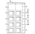
図4には、本実施形態の自動整列方法自動整列後の状態が示されている。これは、図1に示した非整列状態にある複数のアイコンに対して、以下に詳述するような自動整列処理を適用した結果である。ウインドウ20内において、マトリクス状の整列パターンが構築されており、その整列パターンにおける各整列基準方向に沿って(図4に示す例では右方向の各段毎に)各アイコンが自動整列されている。この図4に示す実施形態では、アイコン間における隙間も尊重されており、すなわち整列先後にはそこにアイコンが割り当てられておらず、空欄とされる。また、ウインドウ20内における整列パターン自体も整列基準方向に拡大されている。以下に、この自動整列方法の原理について図5及び図6を用いて詳述する。
【0027】
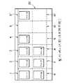
図5及び図6に示す例では、整列先1〜10が初期設定されている。これらの整列先のうちで、整列先1〜5が第1番目の整列基準方向に沿った整列先であり、整列先6〜10が第2段目の整列基準方向に沿った整列先である。
【0028】
このような配列パターンに対して、図1に示したような非整列状態にある複数のアイコンを適当な整列先にそれぞれ割り当てる場合、まず、図5の左側に示すように各整列先毎に割り当て候補が仮決定される。本実施形態では、整列先の領域内に左上隅の座標が含まれるアイコンが当該整列先の候補として決定されている。またいずれのアイコンも候補とならない場合、当該整列先については空白が候補とされている。
【0029】
以上のような処理によって、図5に示すように、整列先1については候補としてアイコン1が決定され、整列先2については候補としてアイコン2、アイコン3及びアイコン4が決定され、整列先3については空白が候補として決定され、整列先4についてはアイコン5が候補として決定され、整列先5については空白が候補として決定される。これと同様に、次の段についてもそれぞれの整列先毎に候補が決定される。
【0030】
ここで、1つの整列先について複数の候補が決定された場合、本実施形態では各候補間に優先順位が決定される。この場合、整列先の基準x座標とアイコンの左上隅のx座標の差が小さいアイコン、その差が同じならば整列先の基準y座標とアイコンの左上隅のy座標の差が小さいアイコン、その差も同じならば重なりの順番が上のアイコン、の順で優先順位が決定される。図5に示した例では、第2の整列先に関し、アイコン2、アイコン3及びアイコン4の順番で優先順位が設定される。
【0031】
このように各整列先後と候補が仮決定された後、以下に列記するルールに基づいて各整列先毎に割り当てる候補が決定される。
【0032】
割り当てルール1:優先順位の最も高いアイコンを割り当てる。
【0033】
割り当てルール2:前の整列先で採用されなかった候補(繰り下がり候補)は次の整列先の候補よりも優先順位の高い候補とする。
【0034】
割り当てルール3:複数の候補の繰り下がりがある場合には前回の優先順位を維持してその繰り下がりを行う。
【0035】
割り当てルール4:空白についてもアイコンと同様に取り扱う。
【0036】
割り当てルール5:改行時点でアイコンの候補が余っていたら表示領域を拡大して各行単位で候補の全てを割り当てる。ただし、空白が最後に残ったらその空白は無視する。
【0037】
以上のような各ルールに従うと、図5に示すように、整列先1についてはアイコン1が割り当てられ、整列先2についてはアイコン2が割り当てられる。この場合、候補として残ったアイコン3及びアイコン4についてはその優先順位を保ったまま次の整列先3の優先的な候補とされる。これが図5に示されている。よって整列先3にはアイコン3が割り当てられることになり、その割り当てで残されたアイコン4及び空白の候補についてはその優先順位の関係が維持されつつ次の整列先4の割り当て処理で候補とされることになる。図5に示す例では、整列先4にアイコン4が割り当てられる。
【0038】
整列先4の割り当て処理で残された空白及びアイコン5の候補は、図6に示すように、整列先5の割り当て処理において優先的な候補とされ、図6に示すように整列先5には空白が割り当てられる。
【0039】
ここで、整列先5についての割り当てを完了しても、依然として候補が残されているため、上述した割り当てルール5にしたがって整列パターンが整列基準方向に拡大され、例えば整列先5’等が追加形成される。そして、その整列先5’には前回の割り当て処理で残されたアイコン5が割り当てられる。最終的に空白の候補が残った場合には、その空白については無視される。もちろん、更に領域を拡大する処理を行ってもよい。
【0040】
以上のような処理は、各整列基準方向毎に実行され、すなわち1つの整列基準方向において候補とされた全てのアイコンなどが割り当てられるまで領域が拡大される。
【0041】
上述した処理を次の段についても実行することによって、整列先6についてはアイコン6が割り当てられ、整列先7についてはアイコン7が割り当てられ、整列先8についてはアイコン8が割り当てられる。更に整列先9,10,10’については空白が割り当てられ、すなわち空欄とされる。
【0042】
以上のような自動整列によれば、図1及び図4の対比から明らかなように、最初にユーザなどが設定した各アイコン間の位置関係を尊重しつつ各アイコンを自動整列させることができる。すなわち、各基準方向における各アイコン間の並びはそのまま維持され、しかも故意にアイコン間に一定の空間を設けたような場合には、それが空欄として表示され、その意味においても原配列を尊重できる。
【0043】
したがって、図2に示したように、特定のアイコンが突然離れた位置に割り当てられてしまうような従来の問題を有効に解決できる。なお、上述した実施形態では、割り当てルール4にしたがって空白についてもアイコンと同様に取り扱ったが、ウインドウ内におけるアイコンの効率的な配置などの事情がある場合には空白を候補から除外したり、空白が割り当てられた場合には次のアイコンを順次積めていくような処理を行ってもよい。これについては後に説明する。
【0044】
上述したアイコンの自動整列手法は、例えばスキャナによって読み込んだ複数の伝票をその縮小イメージとしてアイコンで表示して整理するようなシステムにおいて有用である。例えば、図1に示したように、縮小イメージとして複数の伝票がユーザによって大まかに配列されているような状態において、上記手法を適用すれば、図4に示すような整列後の状態を速やかに得ることができる。このように各アイコンにナンバリング等がされていないような場合でも、各アイコンの原配置位置を尊重して自動整列を行うことができる。なお、上記のようなシステムでは、各アイコンに自動的にファイル名や作成日時などの情報が付加されるが、各アイコンは伝票の縮小イメージであるため、その内容をみることによってユーザは容易に各アイコンの象徴先を特定することができる。
【0045】
上述した割り当てルールは代表例であって、他のルールを追加することもでき、あるいは一部のルールを削除することもできる。ただし、候補の繰り下げや領域拡大などのルールは非常に有効であり、それらの基本的なルールを維持しておくことが望ましい。
【0046】
次に、本実施形態に係る自動整列処理についてその具体例を更に説明する。
【0047】
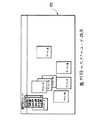
図7に示すように、ウインドウ20内に複数のアイコンが非整列状態で配置されている場合に、ユーザによって配列パターンを決定するために、整列枠の大きさが選択される。これは例えばウインドウ20のメニューバーにおける特定メニューをプルダウンすることによって表示されるリスト中から、特定の枠の大きさを選択することによって実現される。このように、整列枠の大きさを選択すると、図8に示すようにウインドウ20内に仮想的に整列パターンが形成され、すなわちマトリクス上に複数の整列先が確定される。
【0048】
ちなみに、ウインドウ20の垂直方向(列方向)の大きさはWYでありウインドウ20の水平方向(行方向、整列基準方向)の大きさはWXである。各整列先は、垂直方向にDYの大きさを有し、水平方向にDXの大きさを有する。各アイコンの位置はその左上隅の座標(x,y)によって定義される。もちろん、それ以外の基準点(例えば中心点)等をアイコンの座標としてもよい。DX及びDYの決定に当たっては、ユーザが入力した用紙サイズに対して、アイコンのファイル名表示領域とアイコンのページ数表示領域と描画マージンとが加算され、これによってDX及びDYが決定される。
【0049】
以上のような前提の下、図9に示す処理が実行される。S101では、ウインドウ内に存在しているアイコンの位置が取得される。そして、S102では注目している整列先の領域にS101で取得されたアイコンの基準点が属すか否かが判断される。S102で当該整列先の領域に属すと判断された場合、S103が実行され、メモリ上に管理されている候補リストに当該アイコンが追加される。そして、S104では、以上の処理をアイコンの個数だけ繰り返したか否かが判断され、S105では、全ての整列先について上記処理が繰り返されたか否かが判断される。すなわち、S101〜S105までの工程では、図5に示したように、各整列先毎に全てのアイコンについて領域の属否が調査され、整列先の領域内に属するアイコンのみが候補として判定される。
【0050】
例えば、最初の整列先1の領域は、その左上の座標が(0,0)で右下の座標が(DX,DY)の範囲にあり、その範囲に対して全てのアイコンの属否を調査し、いずれかのアイコンの左上隅の座標がこの範囲内に含まれればそのアイコンが候補とされる。これと同様に、整列先2の領域は、その左上隅の座標が(DX,0)で右下隅の座標が(DX×2,DY)の範囲にあり、その範囲に対して各アイコン毎にその属否が調査される。そして、これが各整列先毎に繰り返し実行される。領域の属否を判定する時に、既に候補となっているアイコンは判定対象からはずして良い。
【0051】
このような処理によって、図5に示したように各整列先毎に1又は複数の候補が決定される。ここで、その候補にはこの実施形態では空白が含まれる。
【0052】
図9に示すS106では、整配列基準方向に沿って順番に各整列先毎に優先順位の最も高いアイコンが配置される。すなわち、これによって当該整列先に対する候補の割り当てがなされる。S107では、前の整列先で残された候補が次の整列先の候補としてリストに加えられる。すなわち候補リストが更新される。S108では、以上の処理が整列基準方向に沿った複数の整列先分だけ繰り返されたか否かが判断され、これによって整列基準方向に沿った第1番目の配列先から最終の配列先までアイコン又は空白が順次割り当てられていくことになる。
【0053】
S109では、最後の整列先に対する割り当てが完了した時点で、候補が残っているか否かが判定される。1又は複数の候補が残っていれば、その残存した候補の個数に応じて表示領域が整列基準方向に拡大され、S111において、残された候補間における優先順位にしたがって、拡張された各整列先にそれぞれの候補が配置される。これは図6に示したとおりである。
【0054】
S112では全ての整列基準方向について上記処理が終了したか否かが判断される。すなわち、S106〜S112までの工程は、各整列基準方向毎に繰り返し実行されることになる。図9に示す処理が完了した時点では、図4に示したように各整列先に適切なアイコンが割り当てられ、すなわちアイコンが自動的に対応する整列先に移動されることになる。
【0055】
上述した実施形態によれば、文書が縮小表示された各アイコンの位置関係をそのまま維持させつつ、ユーザが指定した間隔で重なりなく自動的にアイコンを整列させることができるので、各アイコンが見易くなり、アイコンの比較や選択が簡単になるという利点がある。また、領域属否や優先順位の決定に当たっては、座標の比較演算が実行されているため、従来の最短距離の計算などに比べて、その計算量が少ないという利点がある。
【0056】
上述した実施形態では、各アイコンの大きさが統一されている場合について説明したが、二種以上の大きさをもったアイコンの自動整列に当たっても上記手法を適用できる。この場合には、例えば複数のアイコンの中で、アイコンの高さと幅のそれぞれの最大値を求め、高さの最大値をDYとし、幅の最大値をDXとして整列間隔を決めればよい。あるいは、図9に示す処理を実行した後に、すなわち自動整列後における各アイコンの大きさに適合させて行幅及び列幅を決定してもよい。これを以下に説明する。
【0057】
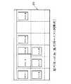
図10には、大きさの異なる複数のアイコンが整列される前の状態が示されている。これに対し上記の図9に示した手法を適用すれば、図11に示すように各アイコンを自動整列させることができる。しかしながら、各整列枠の大きさはまだ調整されておらず、このため一部のアイコン間において部分的に重なりが生じている。
【0058】
そこで、各整列枠の大きさを各アイコンの大きさに合わせることによって、例えば図12に示すようにウインドウ20内において各アイコンを効率的に配置することが可能となる。この処理について図13を用いて説明する。
【0059】
この図13に示す処理は、図9に示す処理が完了した後に引き続いて実行されるものである。
【0060】
まず、S201では、変数iに初期値として1が代入される。このiは行番号に相当するものである。S202では、ウインドウ20内において、左上が(0,(i−1)×DY)で、右下が(WX,i×DY)の範囲の中にある複数のアイコンのうちで、高さの最大値が求められる。そして、S203では、以上のように求められた高さの最大値に対し、ファイル名表示領域の高さとページ数表示領域の高さと描画マージンとが加算される。ただし、アイコンが存在しない場合には予め定めた空白領域用の所定値が演算値として用いられる。S204では、以上のように求められた加算値(あるいは所定値)が上からi番目の行の高さとして設定され、それがメモリに記憶される。
【0061】
S205では、最終行まで上記処理が実行されたか否かが判断され、noであればS206においてiが1つインクリメントされ上記処理が繰り返し実行される。これによって、各行毎にその高さすなわち垂直方向の幅が確定されることになる。
【0062】
S207では、変数jに初期値として1が代入される。ここでjは列番号に相当するものである。
【0063】
S208では、ウインドウ20内において、左上が((j−1)×DX,0)で、右下が((j×DX,WY)の範囲内にある複数のアイコンの中で幅の最大値が求められる。そして、S209では、以上のように求められた幅の最大値に対して、ファイル名表示領域の幅とページ数表示領域の幅を描画マージンとが加算される。ただし、アイコンがない場合には予め定められた空白領域用の所定値が演算値として用いられる。
【0064】
S210では、以上のように求められた加算値(あるいは所定値)が左からj番目の列の幅として決定され、それがメモリに記憶される。
【0065】
S211では、全ての列について上記処理がなされたか否かが判断され、noであればS212において変数jが1つインクリメントされ、上記処理が繰り返し実行される。したがって、以上の処理によって各列ごとにその水平方向の幅が確定されることになる。
【0066】
そして、S213では、以上のように確定された各行及び各列の幅にしたがって各アイコンが再配置される。この状態が図12に示されている。S214では、必要であれば表示領域が拡大あるいは縮小される。
【0067】
以上の実施形態によれば、様々な大きさのアイコンが混在していても、重なりなくかつ表示領域内において効率的にアイコンを配置することができる。
【0068】
また、上記の実施形態では空白を候補に利用したが、そのような空白を候補にすることなく上記処理を行うこともできる。すなわち、このような処理を行えば、図4に示した整列先後の空欄などが取り除かれ、各アイコンが左詰めで密集配列される。ちなみに、例えば図5に示した候補決定に当たっては、整列先3及び整列先5等の候補は無しとなる。ただし、それ以前の整列先から繰り下げられたアイコンがそれぞれの整列先の候補として再決定される。以上の実施形態によれば、アイコンの位置関係を保ったまま表示領域の拡張を最小限にしつつ一覧表示を行える。
【0069】
また、上記の実施形態では整列基準方向が右方向であったが、その整列基準方向を下方向に設定することもできる。すなわち整列基準方向を下方向に設定してその方向を順次右方向へシフトさせるものである。このような処理によっても上記手法をそのまま適用することができ、例えば、その結果、図14に示すような整配列パターンを得られる。この図14に示されるように、上記処理では下方向に領域が拡大されている。なお、他の方向を整列基準方向としても上記手法を適用できる。
【0070】
また、上記実施形態では、アイコンの基準位置を左上隅の座標としたが、それ以外の座標を基準座標としてもよい。また、優先順位の決定に当たって、アイコンの左上隅の座標を利用したが、それに関しても他の基準座標を利用してもよい。
【0071】
さらに、表示領域のいずれかの位置にアイコンが表示されない部分がある場合には、当該部分の領域を縮小することもでき、より効率的な表示を実現できる。
【0072】
【発明の効果】
以上説明したように、本発明によれば、計算量が少なく、またアイコンの原配列パターンをできる限り尊重できるアイコンの自動整列を実現できる。
【図面の簡単な説明】
【図1】 アイコンの整列前の状態を示す説明図である。
【図2】 従来におけるアイコンの自動整列後の状態を示す説明図である。
【図3】 本実施形態のハードウエア構成を示すブロック図である。
【図4】 本実施形態によるアイコンの自動整列後の状態を示す説明図である。
【図5】 本実施形態のアイコンの自動整列の原理を示す説明図である。
【図6】 本実施形態のアイコンの自動整列の原理を示す説明図である。
【図7】 整列枠の大きさの選択方法を示す説明図である。
【図8】 各整列先の幅及び高さの定義を説明するための図である。
【図9】 本実施形態の方法を示すフローチャートである。
【図10】 大きさの異なる複数のアイコンが非整列状態にあることを示す説明図である。
【図11】 アイコンの整列後の状態を示す説明図である。
【図12】 整列枠の大きさを調整した後の状態を示す説明図である。
【図13】 整列枠の大きさの調整を行う方法を示すフローチャートである。
【図14】 整列基準方向を下方向に設定した場合の自動整列結果を示す説明図である。
【符号の説明】
1〜10 整列先、11 CPU、12 バス、14 記憶部、16 表示装置、18 入力装置、20 ウインドウ。[0001]
BACKGROUND OF THE INVENTION
The present invention relates to an icon display control apparatus and method, and more particularly to automatic alignment of a plurality of icons displayed in an unaligned state.
[0002]
[Prior art]
Several proposals have been made regarding a technique for automatically aligning icons according to a predetermined alignment pattern when a plurality of icons are displayed in a non-aligned state in a window.
[0003]
Japanese Patent Application Laid-Open No. 6-4256 discloses a method in which a priority order is set for each icon and a plurality of icons are automatically arranged according to the setting order. In this publication, as the prior art, a method for preferentially assigning an icon having the shortest distance to the reference point to the reference point is disclosed.
[0004]
Japanese Patent Application Laid-Open No. 7-219742 discloses a method of determining a combination that minimizes the amount of movement of each icon when a plurality of icons are assigned to a plurality of reference points, and automatically arranging the icons based on the combination. ing.
[0005]
[Problems to be solved by the invention]
However, the technique described in the above-mentioned Japanese Patent Application Laid-Open No. 6-4256 has a problem that the original arrangement state of the icons before the automatic alignment is not fully respected. For example, when a user moves each icon, even though there is a positional relationship between the icons, or even though the user intentionally has a space between the icons, There was a problem of being ignored by automatic alignment. Note that even if icons are assigned based on only the shortest distance from the reference point, the same problem as described above cannot be solved sufficiently.
[0006]
Further, the method disclosed in Japanese Patent Laid-Open No. 7-219742 has a problem that if the number of icons is large, the amount of calculation becomes very large and the processing time cannot be ignored. In particular, in this method, as shown in FIG. 2, when most icons are arranged along the alignment destination and some icons are overlapped with a narrow range, as shown in FIG. After the arrangement, the overlapping icons (icon 4) are arranged in an unexpected position, and the original arrangement pattern cannot be respected. 1 and 2, reference numeral 1-10 indicates the number of each alignment destination after automatic alignment, and
[0007]
The present invention has been made in view of the above-described conventional problems, and an object of the present invention is to realize automatic icon alignment that requires a small amount of calculation and respects the original icon arrangement pattern as much as possible.
[0008]
[Means for Solving the Problems]
(1) In order to achieve the above object, the present invention provides:DuplicateIn an icon display control device for aligning a number of icons according to a predetermined alignment pattern,There are provisional determination means for tentatively determining neighboring icons having a predetermined positional relationship with each alignment destination of the alignment pattern as candidates for the alignment destination, and there are a plurality of candidates tentatively determined by the temporary determination means for one alignment destination. A priority order assigning means for sequentially assigning a higher priority order from a candidate closest to the sorting destination;Along the reference direction of the alignment pattern,Assignable to each sort destinationWeatherA means to determine the complement, which was not adopted in the previous alignment destinationMeans for adding a carry-down candidate with a higher priority than a normal candidate as the alignment destination candidate and, when there are a plurality of the carry-down candidates, maintaining a priority among them and determining as the alignment destination candidate When,Assigning means for allocating only one candidate to the sorting destination, assigning the candidate to the sorting destination, and assigning a candidate having the highest priority among the sorting destinations for which a plurality of candidates are determined to the sorting destination It is characterized by including these.In a preferred aspect of the present invention, the provisional determination means provisionally determines a blank as a candidate for the alignment destination when the neighborhood icon does not exist.
[0009]
According to the above configuration, one or more candidates are determined for each alignment destination. In this case, preferably, the candidate includes “blank”. When there are a plurality of candidates, priority is set between them. Then, basically, the candidate with the highest priority is assigned to the sorting destination. That is, if the candidate is an icon, the icon is moved to the alignment destination, and if the candidate is blank, no icon is assigned to the alignment destination and is left blank.
[0010]
In the present invention, when one or a plurality of candidates that have not been adopted at a certain alignment destination exist, the candidates are used as a next alignment destination candidate. In this case, the priority of the carry-down candidate is set higher than that of the normal candidate. That is, since the carry-down candidates are preferentially assigned, the original arrangement is respected.
[0011]
When candidate determination and assignment as described above are sequentially executed from the top arrangement destination along the reference direction, each icon is sequentially assigned to the most appropriate arrangement destination while maintaining the original arrangement of the icons. Become. In this case, if the blank is one of the candidates, an automatic arrangement reflecting the intention can be realized when the icons are arbitrarily separated. The above processing is executed for each stage in the row direction, for example. Of course, the processing may be executed along the column direction.
[0012]
(2) In a preferred aspect of the present invention, when unassigned candidate icons remain when assignment to the last alignment destination in the reference direction is completed, the reference direction is maintained until those candidate icons are assigned. And a pattern enlarging means for enlarging the alignment pattern by additionally forming an alignment destination.
[0013]
According to the enlargement of the alignment pattern as described above, all of the plurality of icons arranged approximately along the reference direction can be arranged in the reference direction, and the original arrangement can be maintained in that sense. In this case, it is desirable to enlarge the alignment pattern in consideration of the relationship with the size of the window.
[0014]
(3) In a preferred aspect of the present invention, the alignment pattern is a two-dimensional matrix pattern, and the reference direction is a row direction or a column direction. That is, the above processing can be applied along an arbitrary direction.
[0015]
(4) In a preferred aspect of the present invention, the alignment destination to which the blank is assigned is blank. That is, if the blank is also one of the candidates as described above, as a result, a blank area where no icon is displayed can be formed, and the original array image can be maintained. Of course, if the blank is removed from the candidates, a display form in which the spaces between the icons are filled without any blank space can be realized.
[0016]
(5) In a preferred aspect of the present invention, the basic candidate condition includes a condition in which an icon to which a reference point belongs in a region to be arranged is the neighborhood icon. When the area to be aligned is defined as a two-dimensional area, if the reference point of the icon is included in the area, it is regarded as a neighborhood icon. In this case, the reference point is, for example, the coordinates of the upper left corner of the icon. Other than this, the center point or other specific points may be used as the reference point. In this way, using the determination of whether an area belongs or not (comparison) has the advantage that the calculation amount can be reduced by avoiding the distance calculation.
[0017]
(6) In a preferred aspect of the present invention, the priority order determination means sets a higher priority order than the normal candidates for the lowered candidates, and when a plurality of candidates are lowered, It is characterized in that the priority order between the two is maintained even if it is lowered. That is, the alignment between candidates is maintained to respect the original alignment.
[0018]
(7) In a preferred aspect of the present invention, in the case where a plurality of icons are included as normal candidates, the priority order determination means sequentially sets a higher priority from the icon closest to the alignment destination among them. It is characterized by giving.
[0019]
(8) According to a preferred aspect of the present invention, there is provided means for variably setting the arrangement pattern in conformity with icons of various sizes. If the form of the alignment pattern is appropriately adjusted according to the size of the icon, overlapping between icons can be prevented and icons can be arranged efficiently.
[0020]
(9) In order to achieve the above object, the present invention provides:DuplicateIn an icon display control method for aligning a number of icons according to a predetermined alignment pattern,There are a provisional determination step for provisionally determining neighboring icons that are in a predetermined positional relationship with each alignment destination of the alignment pattern as candidates for the alignment destination, and a plurality of candidates that are provisionally determined by the provisional determination step exist for one alignment destination. A priority ordering step of sequentially assigning a higher priority from the candidate closest to the alignment destination;Along the reference direction of the alignment pattern,Assignable to each sort destinationWeatherThe process of determining the complement,in frontIt was not adopted in the alignment destination ofA step of adding a carry-down candidate as a candidate for the sorting destination with a higher priority than a normal candidate and, when there are a plurality of the carry-down candidates, maintaining a priority among them and determining the candidate as the sorting destination When,For an alignment destination for which only one candidate has been determined, the candidate is assigned to the alignment destination, and for an alignment destination for which a plurality of candidates have been determined, the highest priority candidate among them is assigned to the alignment destination.ProcessIt is characterized by including these.
[0021]
If the blank is not a candidate, each icon will be displayed along the reference direction after automatic alignment. In this case, there is an advantage that an empty space in the window can be reduced.
[0022]
(10)In a preferred aspect of the present invention, the means for variably setting includes:The maximum value of the icon height is calculated for each line, and the height of the line to be arranged is determined according to the maximum value.AndThe maximum value of the icon width is calculated for each column, and the width of the column at the sorting destination is determined according to the maximum value.AndUsing the determined height and width of the alignment destinationSet the array patternIt is characterized by.
[0023]
DETAILED DESCRIPTION OF THE INVENTION
DESCRIPTION OF EXEMPLARY EMBODIMENTS Hereinafter, preferred embodiments of the invention will be described with reference to the drawings.
[0024]
FIG. 3 shows a main configuration of the icon display control device according to the present invention. This icon display control device is realized by, for example, a general-purpose computer.
[0025]
The
[0026]
FIG. 4 shows a state after the automatic alignment method automatic alignment of the present embodiment. This is a result of applying an automatic alignment process described in detail below to a plurality of icons in the non-aligned state shown in FIG. In the
[0027]
In the example shown in FIGS. 5 and 6, the
[0028]
When assigning a plurality of non-aligned icons as shown in FIG. 1 to appropriate arrangement destinations for such an arrangement pattern, first assign them for each arrangement destination as shown on the left side of FIG. Candidates are provisionally determined. In the present embodiment, an icon that includes the coordinates of the upper left corner in the area of the alignment destination is determined as the alignment destination candidate. If none of the icons is a candidate, a blank is a candidate for the alignment destination.
[0029]
As a result of the above processing, as shown in FIG. 5,
[0030]
Here, when a plurality of candidates are determined for one alignment destination, in the present embodiment, a priority order is determined between the candidates. In this case, an icon having a small difference between the reference x coordinate of the alignment destination and the x coordinate of the upper left corner of the icon, and an icon having a small difference between the reference y coordinate of the alignment destination and the y coordinate of the upper left corner of the icon, If the difference is the same, the priority order is determined in the order of the overlapping icons in the upper order. In the example illustrated in FIG. 5, priorities are set in the order of the
[0031]
In this way, after each sorting destination and candidates are provisionally determined, candidates to be assigned to each sorting destination are determined based on the rules listed below.
[0032]
Assignment rule 1: Assign the icon with the highest priority.
[0033]
Allocation rule 2: Candidates that have not been adopted at the previous sorting destination (carrying-down candidates) are those with higher priority than the next sorting destination candidate.
[0034]
Allocation rule 3: When there are multiple candidate roll-downs, the previous priority order is maintained and the roll-down is performed.
[0035]
Allocation rule 4: A blank is handled in the same manner as an icon.
[0036]
Assignment rule 5: If there are more icon candidates at the time of line feed, the display area is expanded and all candidates are assigned in units of lines. However, if a blank is left at the end, it is ignored.
[0037]
According to the above rules, as shown in FIG. 5, the
[0038]
As shown in FIG. 6, the blank and
[0039]
Here, even if the assignment for the
[0040]
The processing as described above is executed for each alignment reference direction, that is, the area is expanded until all icons or the like that are candidates in one alignment reference direction are assigned.
[0041]
By executing the above-described processing also for the next stage, the
[0042]
According to the automatic alignment as described above, as is clear from the comparison between FIG. 1 and FIG. 4, the icons can be automatically aligned while respecting the positional relationship between the icons initially set by the user or the like. That is, the arrangement between the icons in each reference direction is maintained as it is, and when a certain space is intentionally provided between the icons, it is displayed as a blank, and the original arrangement can be respected also in that sense. .
[0043]
Therefore, as shown in FIG. 2, it is possible to effectively solve the conventional problem that a specific icon is suddenly assigned to a distant position. In the above-described embodiment, blanks are handled in the same manner as icons according to the
[0044]
The above-described automatic icon alignment method is useful in a system in which, for example, a plurality of slips read by a scanner are displayed as icons as reduced images and arranged. For example, as shown in FIG. 1, when the above method is applied in a state where a plurality of slips are roughly arranged as a reduced image by the user, the state after alignment as shown in FIG. Obtainable. Thus, even when the icons are not numbered or the like, the original arrangement position of each icon can be respected and automatic alignment can be performed. In the system as described above, information such as the file name and creation date / time is automatically added to each icon. However, since each icon is a reduced image of the slip, it is easy for the user to see the contents. The symbolic destination of each icon can be specified.
[0045]
The allocation rules described above are representative examples, and other rules can be added, or some rules can be deleted. However, rules such as candidate lowering and area expansion are very effective, and it is desirable to maintain these basic rules.
[0046]
Next, a specific example of the automatic alignment processing according to the present embodiment will be further described.
[0047]
As shown in FIG. 7, when a plurality of icons are arranged in the
[0048]
Incidentally, the size of the
[0049]
Under the premise as described above, the processing shown in FIG. 9 is executed. In S101, the position of the icon existing in the window is acquired. Then, in S102, it is determined whether or not the reference point of the icon acquired in S101 belongs to the target alignment destination area. If it is determined in S102 that it belongs to the area to be sorted, S103 is executed, and the icon is added to the candidate list managed on the memory. In S104, it is determined whether or not the above processing has been repeated for the number of icons. In S105, it is determined whether or not the above processing has been repeated for all alignment destinations. In other words, in the steps from S101 to S105, as shown in FIG. 5, whether or not an area belongs to all the icons for each sorting destination is investigated, and only icons belonging to the sorting destination area are determined as candidates. .
[0050]
For example, in the
[0051]
By such processing, one or more candidates are determined for each alignment destination as shown in FIG. Here, the candidate includes a blank in this embodiment.
[0052]
In S106 shown in FIG. 9, the icon having the highest priority is arranged for each alignment destination in order along the standard arrangement reference direction. In other words, candidates are assigned to the sorting destination. In S107, the candidate remaining at the previous alignment destination is added to the list as the next alignment destination candidate. That is, the candidate list is updated. In S108, it is determined whether or not the above processing has been repeated for a plurality of alignment destinations along the alignment reference direction, whereby an icon or a first alignment destination along the alignment reference direction from the first alignment destination to the final alignment destination is determined. Spaces are assigned sequentially.
[0053]
In S109, it is determined whether or not there is a candidate when assignment to the last alignment destination is completed. If one or more candidates remain, the display area is expanded in the alignment reference direction in accordance with the number of remaining candidates, and in S111, each of the alignment destinations expanded according to the priority among the remaining candidates Each candidate is placed in. This is as shown in FIG.
[0054]
In S112, it is determined whether or not the above processing has been completed for all alignment reference directions. That is, the processes from S106 to S112 are repeatedly executed for each alignment reference direction. When the processing shown in FIG. 9 is completed, an appropriate icon is assigned to each sorting destination as shown in FIG. 4, that is, the icon is automatically moved to the corresponding sorting destination.
[0055]
According to the above-described embodiment, it is possible to automatically arrange icons without overlapping at intervals specified by the user while maintaining the positional relationship of the respective icons on which the document is reduced and displayed, so that each icon is easy to see. There is an advantage that the comparison and selection of the icons becomes easy. Further, in determining the region affiliation / priority and the priority order, since a coordinate comparison operation is performed, there is an advantage that the amount of calculation is small compared to the conventional calculation of the shortest distance.
[0056]
In the above-described embodiment, the case where the sizes of the icons are unified has been described. However, the above-described method can be applied even when the icons having two or more sizes are automatically arranged. In this case, for example, among the plurality of icons, the maximum values of the height and width of the icons are obtained, and the alignment interval may be determined by setting the maximum value of the height as DY and the maximum value of the width as DX. Alternatively, the row width and the column width may be determined after executing the processing shown in FIG. 9, that is, according to the size of each icon after automatic alignment. This will be described below.
[0057]
FIG. 10 shows a state before a plurality of icons having different sizes are arranged. On the other hand, if the method shown in FIG. 9 is applied, the icons can be automatically aligned as shown in FIG. However, the size of each alignment frame has not yet been adjusted, so that there is a partial overlap between some icons.
[0058]
Therefore, by matching the size of each alignment frame to the size of each icon, for example, each icon can be efficiently arranged in the
[0059]
The process shown in FIG. 13 is executed after the process shown in FIG. 9 is completed.
[0060]
First, in S201, 1 is assigned to the variable i as an initial value. This i corresponds to the row number. In S202, within the
[0061]
In S205, it is determined whether or not the above processing has been executed up to the last line. If no, i is incremented by 1 in S206 and the above processing is repeatedly executed. As a result, the height, that is, the vertical width is determined for each row.
[0062]
In S207, 1 is assigned to the variable j as an initial value. Here, j corresponds to a column number.
[0063]
In S208, in the
[0064]
In S210, the added value (or predetermined value) obtained as described above is determined as the width of the j-th column from the left, and is stored in the memory.
[0065]
In S211, it is determined whether or not the above processing has been performed for all columns. If no, the variable j is incremented by 1 in S212 and the above processing is repeatedly executed. Therefore, the width in the horizontal direction is determined for each column by the above processing.
[0066]
In S213, the icons are rearranged according to the width of each row and each column determined as described above. This state is shown in FIG. In S214, the display area is enlarged or reduced if necessary.
[0067]
According to the above embodiment, even if icons of various sizes are mixed, the icons can be efficiently arranged in the display area without overlapping.
[0068]
In the above embodiment, a blank is used as a candidate, but the above processing can be performed without using such a blank as a candidate. That is, if such processing is performed, the blank space after the alignment destination shown in FIG. 4 is removed, and the icons are arranged in a densely packed manner with left alignment. Incidentally, for example, in the candidate determination shown in FIG. 5, there are no candidates such as the
[0069]
In the above embodiment, the alignment reference direction is the right direction. However, the alignment reference direction can be set downward. That is, the alignment reference direction is set downward and the direction is sequentially shifted to the right. The above method can be applied as it is also by such processing. For example, as a result, an array pattern as shown in FIG. 14 can be obtained. As shown in FIG. 14, in the above process, the area is expanded downward. It should be noted that the above method can be applied even when another direction is used as the alignment reference direction.
[0070]
In the above embodiment, the reference position of the icon is the upper left corner coordinate, but other coordinates may be used as the reference coordinate. Further, in determining the priority order, the coordinates of the upper left corner of the icon are used, but other reference coordinates may also be used in this regard.
[0071]
Furthermore, when there is a part where the icon is not displayed at any position in the display area, the area of the part can be reduced, and more efficient display can be realized.
[0072]
【The invention's effect】
As described above, according to the present invention, it is possible to realize automatic icon alignment that requires a small amount of calculation and respects the original icon arrangement pattern as much as possible.
[Brief description of the drawings]
FIG. 1 is an explanatory diagram showing a state before icons are arranged.
FIG. 2 is an explanatory diagram showing a state after automatic icon alignment in the related art.
FIG. 3 is a block diagram showing a hardware configuration of the present embodiment.
FIG. 4 is an explanatory diagram showing a state after automatic alignment of icons according to the present embodiment.
FIG. 5 is an explanatory diagram showing the principle of automatic icon alignment according to the present embodiment.
FIG. 6 is an explanatory diagram illustrating the principle of automatic icon alignment according to the present embodiment.
FIG. 7 is an explanatory diagram showing a method for selecting the size of the alignment frame.
FIG. 8 is a diagram for explaining the definition of the width and height of each alignment destination.
FIG. 9 is a flowchart illustrating a method according to the present embodiment.
FIG. 10 is an explanatory diagram showing that a plurality of icons having different sizes are in an unaligned state.
FIG. 11 is an explanatory diagram showing a state after the icons are arranged.
FIG. 12 is an explanatory diagram showing a state after adjusting the size of the alignment frame.
FIG. 13 is a flowchart illustrating a method for adjusting the size of the alignment frame.
FIG. 14 is an explanatory diagram showing an automatic alignment result when the alignment reference direction is set to a downward direction.
[Explanation of symbols]
1-10 Alignment destination, 11 CPU, 12 buses, 14 storage unit, 16 display device, 18 input device, 20 window.
Claims (9)
Translated fromJapanese前記整列パターンの各整列先と所定の位置関係にある近傍アイコンを当該整列先の候補として仮決定する仮決定手段と、
前記仮決定手段により仮決定された候補が1つの整列先に対し複数ある場合、当該整列先に最も近い候補から順次高い優先順位を付与する優先順位付与手段と、
前記整列パターンの基準方向に沿って、各整列先に割り当て可能な候補を決定する手段であって、前の整列先で採用されなかった繰り下がり候補を当該整列先の候補として通常の候補よりも高い優先順位で加え、前記繰り下がり候補が複数ある場合にはそれらの間における優先順位を維持して当該整列先の候補として決定する手段と、
1つの候補のみが決定された整列先についてはその候補を当該整列先に割り当て、複数の候補が決定された整列先についてはそれらの中で最も優先順位が高い候補を当該整列先に割り当てる割当て手段と、
を含むことを特徴とするアイコン表示制御装置。In the icon display control unit for aligning themultiple icons in accordance with a predetermined alignment pattern,
Provisional decision means for provisionally deciding a neighborhood icon in a predetermined positional relationship with each alignment destination of the alignment pattern as a candidate for the alignment destination;
When there are a plurality of candidates that are provisionally determined by the provisional determination means, one priority assignment means that sequentially assigns a higher priority from a candidate closest to the alignment destination;
Along the reference direction of the alignmentpattern,from a means for determining the assignablecandidate in each alignmenttarget, beforethe candidate borrow candidate was not adoptedin the alignment destination align targetnormal candidate Adding a higher priority, and when there are a plurality of carry-down candidates, maintaining a priority among them and determining as a candidate for the alignment destination,
Assigning means for allocating a candidate to an alignment destination for which only one candidate is determined, and allocating a candidate having the highest priority among the alignment destinations for which a plurality of candidates are determined to the alignment destination When,
An icon display control device comprising:
前記仮決定手段は、前記近傍アイコンが非存在の場合には空白を当該整列先の候補として仮決定することを特徴とするアイコン表示制御装置。The apparatus of claim 1.
The provisional determination means, when the neighborhood icon does not exist, provisionally determines a blank as a candidate for the alignment destination .
前記基準方向における最後の整列先に対する割り当てが完了した時点で、割り当てられていない候補が残存する場合に、それらの候補が割り当てられるまで前記基準方向に整列先を追加形成して整列パターンを拡大するパターン拡大手段を含むことを特徴とするアイコン表示制御装置。The apparatus according to claim 1or 2 ,
When assignment to the last alignment destination in the reference direction is completed, if unassignedcandidates remain, an alignment destination is additionally formed in the reference direction to expand the alignment pattern until thosecandidates are assigned. An icon display control device comprising pattern enlargement means.
前記整列パターンは2次元の行列パターンであり、前記基準方向は行方向又は列方向であることを特徴とするアイコン表示制御装置。The apparatus according to claim 1or 2 ,
2. The icon display control apparatus according to claim 1, wherein the alignment pattern is a two-dimensional matrix pattern, and the reference direction is a row direction or a column direction.
前記空白が割り当てられた整列先は空欄とされることを特徴とするアイコン表示制御装置。The apparatus of claim2 .
The icon display control apparatus according to claim 1, wherein the alignment destination to which the blank is assigned is blank.
前記基本候補条件は、整列先の領域内に基準点が属するアイコンを前記近傍アイコンとする条件を含むことを特徴とするアイコン表示制御装置。The apparatus according to claim 1or 2 ,
The icon display control apparatus according to claim 1, wherein the basic candidate condition includes a condition in which an icon to which a reference point belongs in an area to be arranged is the neighboring icon.
配列パターンを各種の大きさのアイコンに適合させて可変設定する手段を含むことを特徴とするアイコン表示制御装置。The apparatus according to claim 1or 2 ,
Icon display control device which comprises anarray pattern be adapted to various size of the icon means for variably setting.
前記可変設定する手段は、
行ごとにアイコンの高さのうち最大値を求め、その最大値に応じて、整列先のその行の高さを決定する高さ決定し、
列ごとにアイコンの幅のうち最大値を求め、その最大値に応じて、整列先のその列の幅を決定し、
前記決定された整列先の高さ及び幅を用いて配列パターンを設定する、
ことを特徴とするアイコン表示制御装置。The apparatus of claim 7.
The means for variably setting is:
For each row, the maximum value of the icon height is obtained, and according to the maximum value, the height that determines the height of the row to be aligned is determined,
For each column, the maximum value of the icon width is obtained, and the width of that column is determined according to the maximum value.
Anarray pattern is set using the determined height and width of the alignment destination.
An icon display control device characterized by that.
前記整列パターンの各整列先と所定の位置関係にある近傍アイコンを当該整列先の候補として仮決定する仮決定工程と、
前記仮決定工程により仮決定された候補が1つの整列先に対し複数ある場合、当該整列先に最も近い候補から順次高い優先順位を付与する優先順位付与工程と、
前記整列パターンの基準方向に沿って、各整列先に割り当て可能な候補を決定する工程であって、前の整列先で採用されなかった繰り下がり候補を当該整列先の候補として通常の候補よりも高い優先順位で加え、前記繰り下がり候補が複数ある場合にはそれらの間における優先順位を維持して当該整列先の候補として決定する工程と、
1つの候補のみが決定された整列先についてはその候補を当該整列先に割り当て、複数の候補が決定された整列先についてはそれらの中で最も優先順位が高い候補を当該整列先に割り当てる割当て工程と、
を含むことを特徴とするアイコン表示制御方法。In the icon display control method of aligningmultiple icons in accordance with a predetermined alignment pattern,
A tentative determination step of tentatively determining a neighborhood icon in a predetermined positional relationship with each alignment destination of the alignment pattern as a candidate for the alignment destination;
When there are a plurality of candidates that are provisionally determined by the provisional determination step for one alignment destination, a priority assignment step that sequentially assigns a higher priority from a candidate closest to the alignment destination;
The alignment pattern along the reference directionoffrom a step of determining the assignablecandidate in each alignmenttarget, beforethe candidate borrow candidate was not adoptedin the alignment destination align targetnormal candidate Adding a higher priority, and when there are a plurality of the carry-down candidates, maintaining the priority among them and determining as a candidate for the alignment destination,
An assigningstep of assigning a candidate to an alignment destination for which only one candidate is determined, and assigning a candidate having the highest priority among the alignment destinations for which a plurality of candidates are determined to the alignment destination When,
An icon display control method comprising:
Priority Applications (1)
| Application Number | Priority Date | Filing Date | Title |
|---|---|---|---|
| JP10172897AJP3870478B2 (en) | 1997-04-18 | 1997-04-18 | Icon display control apparatus and method |
Applications Claiming Priority (1)
| Application Number | Priority Date | Filing Date | Title |
|---|---|---|---|
| JP10172897AJP3870478B2 (en) | 1997-04-18 | 1997-04-18 | Icon display control apparatus and method |
Publications (3)
| Publication Number | Publication Date |
|---|---|
| JPH10293677A JPH10293677A (en) | 1998-11-04 |
| JPH10293677A5 JPH10293677A5 (en) | 2005-03-17 |
| JP3870478B2true JP3870478B2 (en) | 2007-01-17 |
Family
ID=14308351
Family Applications (1)
| Application Number | Title | Priority Date | Filing Date |
|---|---|---|---|
| JP10172897AExpired - Fee RelatedJP3870478B2 (en) | 1997-04-18 | 1997-04-18 | Icon display control apparatus and method |
Country Status (1)
| Country | Link |
|---|---|
| JP (1) | JP3870478B2 (en) |
Families Citing this family (5)
| Publication number | Priority date | Publication date | Assignee | Title |
|---|---|---|---|---|
| JP4770634B2 (en)* | 2006-08-07 | 2011-09-14 | 富士ゼロックス株式会社 | Representation image rearrangement device |
| JP5109868B2 (en)* | 2008-08-22 | 2012-12-26 | 富士通株式会社 | Symbol display method and symbol display program |
| JP2015022567A (en)* | 2013-07-19 | 2015-02-02 | 富士ゼロックス株式会社 | Information processing apparatus and information processing program |
| JP7067015B2 (en)* | 2017-10-23 | 2022-05-16 | 富士フイルムビジネスイノベーション株式会社 | Information processing equipment and programs |
| CN110536007B (en)* | 2019-08-16 | 2021-07-13 | 维沃移动通信有限公司 | Interface display method, terminal and computer-readable storage medium |
- 1997
- 1997-04-18JPJP10172897Apatent/JP3870478B2/ennot_activeExpired - Fee Related
Also Published As
| Publication number | Publication date |
|---|---|
| JPH10293677A (en) | 1998-11-04 |
Similar Documents
| Publication | Publication Date | Title |
|---|---|---|
| US7216293B2 (en) | Display control method, program product, and information processing apparatus for controlling objects in a container based on the container's size | |
| US5191644A (en) | Multiwindow control system | |
| US8726214B2 (en) | Floorplanning method for an analog integrated circuit layout | |
| US7499045B2 (en) | Graphics image generation | |
| CN86105001A (en) | The display control method of multi-window system | |
| JP3870478B2 (en) | Icon display control apparatus and method | |
| JP3995114B2 (en) | Switch image display method | |
| CN104571826B (en) | Method, device and system for managing multiple windows on screens of multiple users | |
| JP2996933B2 (en) | Drawing display device | |
| JPH022460A (en) | Abstract image processor | |
| CN116755604A (en) | Data processing device and data processing method | |
| JPH10293676A (en) | Icon display control device and method | |
| CN109165252B (en) | Automatic arrangement method for enterprise-oriented information relationship graph | |
| JP3127551B2 (en) | Layout device | |
| JPH06274303A (en) | Multi-window display method | |
| CN113836878B (en) | Table generation method, device, electronic device and storage medium combining RPA and AI | |
| JPH10293677A5 (en) | ||
| JP3369093B2 (en) | Semiconductor integrated circuit design equipment | |
| JPS61141479A (en) | Reduced character processing method | |
| JP2009181253A (en) | Document processor and program | |
| JPH07168690A (en) | Updating and displaying method for image | |
| JPH04143793A (en) | display device | |
| JP2001022552A (en) | Screen display method of WWW page information and apparatus therefor | |
| JPH0519967A (en) | Touch panel information management method | |
| JPH0696149A (en) | CAD device for electric circuit design |
Legal Events
| Date | Code | Title | Description |
|---|---|---|---|
| A521 | Request for written amendment filed | Free format text:JAPANESE INTERMEDIATE CODE: A523 Effective date:20040415 | |
| A621 | Written request for application examination | Free format text:JAPANESE INTERMEDIATE CODE: A621 Effective date:20040415 | |
| RD04 | Notification of resignation of power of attorney | Free format text:JAPANESE INTERMEDIATE CODE: A7424 Effective date:20040415 | |
| A977 | Report on retrieval | Free format text:JAPANESE INTERMEDIATE CODE: A971007 Effective date:20060622 | |
| A131 | Notification of reasons for refusal | Free format text:JAPANESE INTERMEDIATE CODE: A131 Effective date:20060704 | |
| A521 | Request for written amendment filed | Free format text:JAPANESE INTERMEDIATE CODE: A523 Effective date:20060831 | |
| TRDD | Decision of grant or rejection written | ||
| A01 | Written decision to grant a patent or to grant a registration (utility model) | Free format text:JAPANESE INTERMEDIATE CODE: A01 Effective date:20060926 | |
| A61 | First payment of annual fees (during grant procedure) | Free format text:JAPANESE INTERMEDIATE CODE: A61 Effective date:20061009 | |
| R150 | Certificate of patent or registration of utility model | Free format text:JAPANESE INTERMEDIATE CODE: R150 | |
| FPAY | Renewal fee payment (event date is renewal date of database) | Free format text:PAYMENT UNTIL: 20101027 Year of fee payment:4 | |
| FPAY | Renewal fee payment (event date is renewal date of database) | Free format text:PAYMENT UNTIL: 20111027 Year of fee payment:5 | |
| FPAY | Renewal fee payment (event date is renewal date of database) | Free format text:PAYMENT UNTIL: 20121027 Year of fee payment:6 | |
| FPAY | Renewal fee payment (event date is renewal date of database) | Free format text:PAYMENT UNTIL: 20121027 Year of fee payment:6 | |
| FPAY | Renewal fee payment (event date is renewal date of database) | Free format text:PAYMENT UNTIL: 20131027 Year of fee payment:7 | |
| LAPS | Cancellation because of no payment of annual fees |