JP3870046B2 - Recording apparatus and recording method - Google Patents
Recording apparatus and recording methodDownload PDFInfo
- Publication number
- JP3870046B2 JP3870046B2JP2001236902AJP2001236902AJP3870046B2JP 3870046 B2JP3870046 B2JP 3870046B2JP 2001236902 AJP2001236902 AJP 2001236902AJP 2001236902 AJP2001236902 AJP 2001236902AJP 3870046 B2JP3870046 B2JP 3870046B2
- Authority
- JP
- Japan
- Prior art keywords
- ink
- recording
- combination
- value
- density
- Prior art date
- Legal status (The legal status is an assumption and is not a legal conclusion. Google has not performed a legal analysis and makes no representation as to the accuracy of the status listed.)
- Expired - Fee Related
Links
Images


Classifications
- B—PERFORMING OPERATIONS; TRANSPORTING
- B41—PRINTING; LINING MACHINES; TYPEWRITERS; STAMPS
- B41J—TYPEWRITERS; SELECTIVE PRINTING MECHANISMS, i.e. MECHANISMS PRINTING OTHERWISE THAN FROM A FORME; CORRECTION OF TYPOGRAPHICAL ERRORS
- B41J2/00—Typewriters or selective printing mechanisms characterised by the printing or marking process for which they are designed
- B41J2/005—Typewriters or selective printing mechanisms characterised by the printing or marking process for which they are designed characterised by bringing liquid or particles selectively into contact with a printing material
- B41J2/01—Ink jet
- B41J2/205—Ink jet for printing a discrete number of tones
- B41J2/2056—Ink jet for printing a discrete number of tones by ink density change
- H—ELECTRICITY
- H04—ELECTRIC COMMUNICATION TECHNIQUE
- H04N—PICTORIAL COMMUNICATION, e.g. TELEVISION
- H04N1/00—Scanning, transmission or reproduction of documents or the like, e.g. facsimile transmission; Details thereof
- H04N1/40—Picture signal circuits
- H—ELECTRICITY
- H04—ELECTRIC COMMUNICATION TECHNIQUE
- H04N—PICTORIAL COMMUNICATION, e.g. TELEVISION
- H04N1/00—Scanning, transmission or reproduction of documents or the like, e.g. facsimile transmission; Details thereof
- H04N1/40—Picture signal circuits
- H04N1/40087—Multi-toning, i.e. converting a continuous-tone signal for reproduction with more than two discrete brightnesses or optical densities, e.g. dots of grey and black inks on white paper
Landscapes
- Engineering & Computer Science (AREA)
- Multimedia (AREA)
- Signal Processing (AREA)
- Physics & Mathematics (AREA)
- Discrete Mathematics (AREA)
- General Physics & Mathematics (AREA)
- Ink Jet (AREA)
- Particle Formation And Scattering Control In Inkjet Printers (AREA)
- Dot-Matrix Printers And Others (AREA)
- Printers Characterized By Their Purpose (AREA)
Abstract
Description
Translated fromJapanese【0001】
【発明の属する技術分野】
本発明は、記録装置及び記録方法に関し、特に画像を多階調で記録する記録装置及び記録方法に関する。
【0002】
【従来の技術】
様々な記録方式のプリンタの中で、記録媒体に記録剤を付着することで記録媒体上にテキストや画像を形成するものがある。このような記録方式の代表例として、インクジェット記録装置がある。近年、インクジェット記録装置の性能が向上し、テキストばかりでなく、画像も記録されるようになってきた。
【0003】
インクジェット記録装置では、記録速度向上等のために、同一色同一濃度のインクを吐出可能な複数のインク吐出口(ノズル)を集積配列したノズル群を用い、さらに、このようなノズル群が、同一色で異なる濃度のインクや、異なる色についてそれぞれ配設されているのが通例である。また、同一色同一濃度のインクを吐出量を何段階かに変えて吐出可能としたものもある。
【0004】
これらのノズル群を設けたヘッドを、記録媒体に対して相対的に移動させつつノズルからインクを吐出させ、記録を行なう。
【0005】
ヘッドを記録媒体に対し、相対的に移動させる方法として、
(i)ノズル群は、X方向に略並行に配置され、記録媒体が停止している間に、X方向と直交する方向(Y方向)に記録ヘッドを移動させ、この間に記録を行い、その後記録媒体を間欠的にX方向に所定距離移動させ、ついで再度記録ヘッドをY方向に移動させ、以下、この動作を繰り返すことで記録を行なう、いわゆるスワスプリント方式
(ii)ノズル群を記録媒体のY方向の全幅分カバーするように固定して設け、記録媒体をX方向に一定速度で移動させる間に記録する、いわゆるフルマルチプリント方式
が実施されている。
【0006】
これらの方法で画像を記録する場合、画像を構成する単位として、画素が定義される。画素は、必ずしも、1つのドット(1つのノズルから1回のインク吐出によって記録媒体上に形成される部分)で構成されているとは限らず、一つの画素を複数のドットで形成するようにしても良い。複数のドットで形成する場合、略同じポイントに重ねて記録されても良いし、隣接するポイントに記録しても良い。いずれにせよ、予め決められた規則に従って決定される。記録すべき画像データは、画像処理手段によって、記録装置に適合した画像サイズになるように拡大補間、縮小等の処理をされる。次いで、それぞれの画素に対して、記録すべき色と濃度とが予め決められた規則に従って決定され、この決定に従って記録が実行される。前述のように、一つの画素は複数のドットで構成されても良いので、その場合は、一つの濃度とは限らず、異なる濃度のインクが選択され得る。吐出量可変のヘッドを使用している場合は、適宜吐出量すなわちドットのインク量を変えても良い。また、これらを組み合わせても良い。
【0007】
画像を記録する場合、画像データの階調を忠実に再現する方法として、ディザ法、誤差拡散法などの中間調処理法が行われる。さらに、ディザ法や誤差拡散法において、一つの画素の階調を多くすることで、より多くの階調を表現可能となる。このような記録方法の具体例は、特開平10−324002号公報に記載されている。
【0008】
すなわち、一つの色について、濃度の異なるインクを吐出可能なノズル群を用意しておき、これらのノズル群から、一つの画素に対して予め決められた限度内で選択的に複数回記録(以下重ね打ちと記述)することで、この画素で表現可能な濃度(記録OD値)の階調を多くすることができる。例えば、6種類の異なる濃度のインクを吐出可能なノズル群を用意し、600dpiの一つの画素を4回以内の重ね打ちを行なうとすると、50階調以上の表現が可能である。一つの画素を、隣接するポイント2×2で構成し、合計16回以内の重ね記録で構成するとすると、200階調以上の表現が可能である。濃度の異なるインクを吐出可能なノズル群を用意する変わりに、ノズルから吐出されるインクの量を可変とし、ドットのインク量を可変とすることで階調を表現しても良い。またこれらの組み合わせで階調を表現しても良い。
【0009】
これらの場合、表現しようとする画素の濃度(所望OD値)とインクの重ね記録の方法を対応させる規則を予め決めておき、この規則に従って実際の記録、すなわち、どのノズルでいつインクを吐出するか決定され、これに従って実際の記録制御手段により記録が行われる。
【0010】
一例としては、それぞれのインクで記録した場合の画素の記録OD値を測定しておき、この測定値によって、重ね打ちした場合の記録OD値を決定し、各重ね打ちパターンに対する画素の記録OD値を記述したテーブルを用意する。そして、記録すべき画素の所望OD値に近い記録OD値の重ね打ちのパターンを選択する。誤差拡散処理の場合は、記録すべき画素の所望OD値とテーブルの記録OD値との差を求め、これを誤差として隣接画素に振り分ける。
【0011】
【発明が解決しようとする課題】
世の中にはいろいろな画像が存在するが故に、プリンタに要求される特性も、用途や目的によってさまざまである。望ましくは、使用する用途に応じた、いろいろなプリンタを設計する場合に、記録特性を自由に設計できれば好ましい。
【0012】
特殊な記録特性を要求される例として、医療画像の例を述べる。
【0013】
医療画像等の一部の分野では、モノクロで記録されたモノクロ画像が依然として多数使用されている。その理由は、モノクロ画像の方が、人間の目の濃度分解能が高いため、濃度分解能が多く要求される分野においては、カラー画像よりも人間が認識できる情報量が多くなる為である。更に、記録媒体として、反射式のものをもちいるよりも、透過式のものを用いる方が、人間が認識できる濃度分解能が多くなることが知られている。一般的に、カラー画像に対する人間の目の濃度分解能は、8bit程度と言われているのに対し、モノクロ透過画像については、10乃至11bitといわれている。そして、医療用のX線写真やCT・MRI画像を透過メディアに記録されたものにおいては、実際に人間の濃度分解能限度まで読み取られ、診断の為の情報を提供している。このような高階調のモノクロ画像を記録するプリンタとして、画像信号に応じて変調されたレーザー光を銀塩フィルム上に照射し、このフィルムを現像処理することでフィルム上に画像を得るレーザーイメージャがある。このようなレーザーイメージャの場合、ある程度のマージンも見込んで12bitの濃度分解能で記録される場合が多い。しかしながら、このようなレーザーイメージャは高価であり、また、湿式の現像処理が必要であり、廃液処理や、メンテナンスが煩雑などの問題がある。湿式の現像処理を行なう変わりに、加熱することで現像処理を行なう、乾式銀塩方式のレーザーイメージャも存在するが、湿式に比較して画質が劣るという問題がある。
【0014】
他方、特開平10−324002号公報に記載のように、600dpiで50階調以上の濃度階調が可能なインクジェット方式で、更に誤差拡散処理を行なうことで、256階調の記録を行なうものも提案されている。特開平10−324002号公報では、256階調の記録例が示されている。入力画像データを256階調のかわりに4096階調とすれば、4096階調の記録が可能である。
【0015】
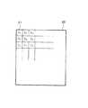
ここで、特開平10−324002号公報の記録ヘッドで使用するインクについて、以下の表1に示す。表1に示されるように使用するインクは6種類であり、濃度の高い方から順にA、B、C、D、E、Fとする。同時に、各インクA〜Fの染料濃度(%)及び透過濃度を示す。尚、各インクは染料及び溶媒からなり、溶媒には、界面活性剤、保湿剤等の各種添加剤が含まれている。これら添加剤は、記録ヘッドからの吐出特性、記録媒体上での吸収特性とを制御するものである。
【0016】
【表1】
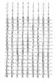
これらのインクを用いて、同一画素に打ち込むインクの種類を最大4とした場合は、一つの画素で表すことのできる階調数は、6+6C2+6C3+6C4+1=57となる。尚、表1では、同一濃度になる組み合わせができないような染料濃度を持つインクが設定してある。また、この時の低濃度側4種のインクドット単独の濃度比は、低濃度側から1:2:4:8になっており、この57階調のうちから53階調を使用して画像を出力する。つまり、上述したように入力画像データ(4096階調)を53値化して画像を出力する。その時の各階調(53階調)を表現するためのインクの種類とその組み合わせを図19に示す。図中、No.の欄は各階調を示している。図中※で示した部分は、低濃度部分での濃度レベルの差が、高濃度部分と比較して小さくなるようにするために使用しない組み合わせを示している。インクA〜Fの欄において、○はそのインクを記録ヘッドから吐出することを示し、×はそのインクを記録ヘッドから吐出しないことを示している。また、d1[i](i=0〜52:整数)の欄は各階調を表現するインク濃度レベルを示している。また、th[i](i=1〜52:整数)の欄は入力画像データを53階調のいずれかの階調に決定するための閾値を示している。尚、閾値は、通常、インク濃度レベルd1[k−1]とインク濃度レベルdl[k]との間の中点のインク濃度レベルとして決定される。
【0018】
ここで各階調を示すインクの種類の組み合わせが組み合わせデータであり、その組み合わせデータに基づいて決定されるインク濃度レベルがインク濃度データである。
【0019】
そして、この53値のインク濃度レベル(d1[0]〜d1[57])と52値の閾値(th[1]〜th[52])を用いて、多値誤差拡散処理部で、入力画像データ(4096階調)を53値化する多値誤差拡散処理を行う。このように、上記公報記載の多値誤差拡散処理は、入力画像データを多値化するための閾値が複数、ここでは52値存在し、この点が通常の誤差拡散処理と大きく異なる。尚、ここでは、多値誤差拡散処理を用いて入力画像データの多値化を行っているが、これに限定されるものではない。例えば、多値平均濃度保存法、多値ディザマトリックス法あるいはサブマトリックス法等の他の多値化の方法を用いて、入力画像データの多値化を行っても良い。
【0020】
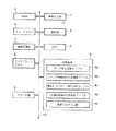
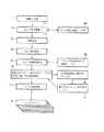
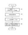
次に、上記公報記載のインクジェット記録装置の記録制御の手順について、図20のフローチャートを参照して説明する。
【0021】
図20は上記公報記載のインクジェット記録装置の記録制御の手順を示すフローチャートである。
【0022】
まず、ステップS1において、インク濃度データ・組み合わせデータ部に、インク濃度データ、組み合わせデータを含む記録ヘッドで使用するインクに関するデータを蓄積する。
【0023】
次に、ステップS2において、入力画像データを入力し、入力画像データが示す各画素について多値誤差拡散処理を行う。
【0024】
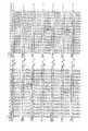
ここで、多値誤差拡散処理の詳細について、図21(a),(b)を参照して説明する。
【0025】
図21(a),(b)は上記公報記載の入力画像データと多値誤差拡散処理後に得られる53値化画像データの配置を示す模式図である。即ち、入力画像データが示す各画素ごとの4096濃度データ(0(黒)〜4095(透明))における画素の配置の一部を示す図である。
【0026】
図21(a)において、f(i,j)は多値化(53値化)しようとする注目画素(i,j)の4096濃度データレベルを有する。また、破線より上の各画素f(i−2,j−1)〜(i−1,j)は、既に多値化(53値化)処理が終了しており、B(i,j)は注目画素(i,j)の多値化(53値化)後の濃度データ("0","137.6",…,"4011.2","4080"の53個の値とする)を示している。また、注目画素(i,j)の多値化(53値化)後は、f(i,j+1),f(i,j+2),…と順次同様の多値化(53値化)処理を行う。
【0027】
まず、注目画素(i,j)の4096濃度データレベルf(i,j)は、閾値th[k]と比較演算する。
【0028】
th[k]≦f(i,j)<th〔k+1]…(1)
B(i,j)=dl[k]…(2)
そして、上記(1)式を満たすkを求め、(2)式により注目画素(i,j)の多値化(53値化)後の濃度データB(i,j)を決定する。
【0029】
続いて、図21(b)に示す誤差拡散マトリックスを用いて、上記の多値化処理で決定された濃度データB(i,j)と多値化処理前の4096濃度データレベルf(i,j)との間に生じた誤差errを、以下に示す(3)式によって演算する。
【0030】
err=f(i,j)−dl[k]…(3)
そして、演算された誤差errを、以下に示す(4)式に従って他の画素へ拡散する。
【0031】
f'(x,y)=f(x,y)+err×M(x−i,y−j)/31…(4)
このように、誤差errは、図21(b)に示すような誤差拡散マトリックスの配分に従い、各画素へ拡散され、以後、この拡散された誤差を含めた値f'(i,j)を用いて、同様に多値化(53値化)処理を行う。
【0032】
ステップS3において、データ分配部において、多値化(53値化)処理によって得られた濃度データB(i,j)に対応する上述した図19に示した組み合わせデータに基づいて、記録ヘッドに対するインク吐出制御データを生成する。例えば、濃度データB(i,j)=1036.8である場合、インクA,インクC,インクD,インクFが吐出されるように、インク吐出制御データを生成する。
【0033】
そして、ステップS4において、記録ヘッド・紙送り制御部において、インク吐出制御データに従って、記録ヘッドの駆動及び記録媒体の搬送を制御することにより階調画像が形成される。
【0034】
尚、上記公報では、600dpi相当のインクジェットヘッド(256ノズルマッチヘッド)を6個使用して、医療用階調画像(透過)を出力した。
【0035】
以上説明したように、上記公報記載の従来技術によれば、記録媒体の搬送方向(副走査方向)に複数種類の濃淡インクを吐出できる記録ヘッドを設け、画像を形成する際には、画素を形成するインクドットを少なくとも1つ以上吐出して記録を行うことで、例えば、1つの記録ヘッドに多くの種類のインクを吐出できる記録ヘッドを新たに作成することなく、従来の記録ヘッドと同様の構成で記録する画像の階調数を増加させることができる。つまり、少なくとも新たな記録ヘッドを作成するような大幅なコストをかけることなく、階調数の多い良好な階調画像を得ることができる。
【0036】
この方式(4096階調)で実際にX線画像を記録したところ、良好な画質が得られた。しかしながら、画像の種類によっては、レーザーイメージャの画質に比較すると、いくつかの画質上の問題が発生した。その一例を以下に説明する。
【0037】
図22はこの方法により透明フィルム上に胸部X線画像を記録した例を示し、100はそのフィルムである。通常のX線写真では、肩の部分は、本来、滑らかに濃度が変わっているが、この例では、101に示す輪郭が現れた。これを本来輪郭のないところに輪郭が現れるという意味で、擬似輪郭と呼ぶ。このような擬似輪郭は、他にも、濃度が滑らかに変化する部分に現れた。この擬似輪郭が現れると、画像の品位が損なわれるばかりでなく、本来の目的である、画像診断にも悪影響を及ばす。
【0038】
このような擬似輪郭がなぜ発生するかについて、解析した結果、以下のような原因であることが判明した。
【0039】
一例として図19を参照し、濃度階調が3043から2974に変化する部分で考えると、この部分では、最初No.37の組み合せが主に使用され、次いでNo.36の組み合せが主に使用される。No.37とNo.36の組み合せを比較すると、No.37では、インクC、D、E、Fが使用され、No.36ではインクBが使用されていて、使用されているインクが大きく変わっていることがわかる。
【0040】
そして、No.37の組み合せが使用されるか、No.36の組み合せが使用されるかは、誤差拡散処理の結果で決定されるが、一般になだらかに階調が変化する部分で、徐々に切り替わるとは限らず、急に切り変わる。
【0041】
ところでインクは、表1にあるような濃度になるように調合するのであるが、実際には誤差が生じる。また、調合されたときには正しい値だったとしても、時間が経過すると、蒸発等により、若干変化する。実験によると、2〜3%の変化は通常起こり得、多い場合は5%程度変化する場合もある。その程度は、濃度変化を仮に3%とすると、例えばBインクだと、透過濃度で0.89×0.03=0.027程度である。すなわち、上記No.37からNo.36の移り変わりにおいて、インクC、D、E、Fが正しい値であったとしても、Bインクが3%変化したとすると、透過濃度で0.027の誤差が生じることを意味する。例えばある微小領域で、50%の画素で上記移り変わりがあると仮定すると、その領域の平均濃度で0.0135の誤差を生じる。
【0042】
他方、透過のフィルムに対し、人間の目の濃度分解能は10bit以上であり、これは、透過濃度に直すと、0.003である。よって、0.003以上の濃度差があると、これを輪郭として認識することになる。つまり、本来輪郭のないところであっても、0.003以上の濃度差があれば、輪郭として認識する。
【0043】
この数字0.003に対して、上述した濃度誤差である0.0135は十分大きい数字であり、この濃度誤差によって、容易に擬似輪郭が現れることになる。更に、ノズルによって吐出量にばらつきがある。均等にばらついていれば、ノズルの数が多いので、平均化効果により、全体としてのばらつきは少なくなるが、チップごとにばらつきに偏りがあると、これも濃度の誤差として現れることになる。
【0044】
もう一つの画質上の問題は、以下のようなことである。
【0045】
誤差拡散方式であると、最小記録OD値に比べて所望OD値が小さい場合、ある閾値までは、インクが打たれず、ある閾値に達した時に初めて最小記録OD値のインクが打たれる。そのため、透明から徐々に濃度が上がる部分で、あるところまで透明で、あるところから急に濃くなる、という現象(掃出し現象)が生じる。
【0046】
また、画質上の問題以外に、誤差拡散処理は記録しようとする画像が変わるたびに、画素ごとに計算が発生するため、処理時間がかかるという問題がある。特に、誤差を周囲の画素に振り分ける際に、掛け算や割り算が多数発生する。画質を向上するために、振り分ける画素を多くするとさらに計算は多くなる。高精細な画像に対応するために、画素の大きさを300dpiや600dpiのように小さくすると、画素数が多く、処理時間がかかる。特に、医療画像の場合、14×17インチの大判のフィルムに記録する場合が多いので、上記問題は深刻である。
【0047】
以上、極めて高いレベルの画質が要求される例を述べたが、画質はそれほどでもないが、高速に記録したい場合、できるだけ機構を簡素化して、しかも高画質が記録できる安価なプリンタが求められる場合もある。
【0048】
本発明は、上述の課題に鑑みてなされ、その目的は、記録画像の用途等に応じて出力特性を容易に変更可能で、高画質の画像を高速に記録できる記録装置及び記録方法を提供することである。
【0049】
【課題を解決するための手段】
上述の課題を解決し、目的を達成するために、本発明の記録装置は、同色系で濃度の異なる複数種のインクを吐出する記録ヘッドを用い、画像データを構成する画素の濃度情報値に基づいて記録媒体上の画素に前記複数種のインクが重なるように吐出することで、当該吐出される複数種のインクの組合せにより表現される濃度を有する画素を含む画像を記録する記録装置であって、複数段階の前記濃度情報値の夫々について、前記画像データを複数のブロックに分割してなる各ブロックを構成する複数の画素各々についての前記ブロック内の位置を表す番地情報と前記画素に吐出すべきインクの組合せを表す組合せ情報とを対応させたデータを格納したデータ格納部と、対象画素の濃度情報値および番地情報に基づき、前記データ格納部に格納されたデータを参照し、前記対象画素に吐出すべきインクの組合せ情報を取得する取得手段と、前記取得手段により取得された前記組合せ情報に基づいて前記記録ヘッドから前記対象画素に対してインクを吐出させる記録制御手段とを具備し、前記データ格納部に格納されたデータが示す前記複数段階の濃度情報値の内、同じ濃度情報値には、ある番地情報と別の番地情報とに対し異なるインクの組合せを表す異なる前記組合せ情報が対応する。
【0050】
また、本発明の記録方法は、同色系で濃度の異なる複数種のインクを吐出する記録ヘッドを用い、画像データを構成する画素の濃度情報値に基づいて記録媒体上の画素に前記複数種のインクが重なるように吐出することで、当該吐出される複数種のインクの組合せにより表現される濃度を有する画素を含む画像を記録する記録方法であって、複数段階の前記濃度情報値の夫々について、前記画像データを複数のブロックに分割してなる各ブロックを構成する複数の画素各々の前記ブロック内の位置を表す番地情報と前記画素に吐出すべきインクの組合せを表す組合せ情報とを対応させたデータを格納したデータ格納部を参照し、対象画素の濃度情報値および番地情報に基づき前記対象画素に吐出すべきインクの組合せ情報を取得する取得工程と、前記取得工程において取得された前記組合せ情報に基づいて前記記録ヘッドから前記対象画素に対してインクを吐出させる工程とを備え、前記データ格納部に格納されたデータが示す前記複数段階の濃度情報値の内、同じ濃度情報値には、ある番地情報と別の番地情報とに対し異なるインクの組合せを表す異なる前記組合せ情報が対応する。
【0051】
【発明の実施の形態】
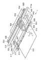
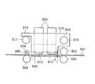
図1は、本発明に係る実施形態のインクジェット記録装置の要部(記録部)を示す斜視図、図2は、図1をA方向から見た側面図、図3はキャリッジを上方向から見た部分詳細図、図4(a)はヘッドを図1の下側から見た部分詳細図、図4(b)はシートにインクが打ち込まれた状態を示す図、図5はキャリッジを下から見た部分詳細図である。
【0052】
図1乃至図5に示すように、501は画像を記録されるシート、502及び503と、504及び505とはそれぞれ対になってシートをX方向に搬送するローラで、505は、長手方向に所定間隔で膨出部506が配設され、506がシート501に接触する。507はモータ、508はモータ軸に取り付けられたプーリ、509及び510はローラ502,504の一端に取り付けられたプーリで、ベルト511によってプーリ508に結合されており、モータの回転によってローラ502,504が回転する。また、ローラ503,505は、不図示の付勢機構によりローラ502,504に押し付けられる方向に付勢され、これらの構成によりシートをX方向に搬送する。512は、複数のヘッド513a〜513rを搭載するキャリッジで、各ヘッドには図4(a)に示すように、多数のノズルがシート面に対面するよう配設されている。516,517は、キャリッジ512を摺動可能に保持するシャフトで、516はキャリッジ512に設けられた孔518を貫通し、また、キャリッジ512に設けられた突起部分519がシャフト517上に当接する構造になっている。これらの構成によって、ヘッド513のノズルの設けられた面が所定距離dでシートに対面する。520は、その1部をキャリッジ512に固定されたベルトで、モータ521の軸に取り付けられたプーリ522及び固定軸523に回転可能に取り付けられたプーリ524との間を結合している。これらの構成によって、モータ521の回転によりキャリッジがY方向及びその反対方向に移動可能となり、シートのY方向全域及び、キャリッジの待機位置である512a及びシートに関して512aと対象の位置に移動可能である。なお、ヘッドがシート上を移動する間、ノズル面とシートの間隔は、所定距離dに保たれるように構成されている。526a〜526rは、インクを入れたインクカートリッジで、ヘッド513a〜513rに装着され、ヘッドにインクを供給するようになっている。ヘッドカートリッジ526a〜526rは、ヘッド513a〜513rに対し、それぞれ着脱自在となっており、インクカートリッジのインクがなくなったら、取り外して新しいインクカートリッジを取り付けることでインクを補給できるようになっている。インクカートリッジは、18個用意されている。その内訳は、一例では黒の濃度の異なるもの8種類(薄い方から#1〜#8)とし、♯1〜♯4を1個、#5を2個、#6〜♯8を各4個である。525は、ローラ502,504間に設けられたシートガイドである。515は、シート上にノズルでインクを吐出した時にシート上に形成されるドットである。
【0053】
図6は記録制御手段のブロック図である。
【0054】
図6に示すように、1はスキャナ、X線撮影装置、X線CTスキャナ装置、MRI装置などの外部機器からの画像データを入力するための画像入力部で、記録しようとする画像の各画素に対する画像データ(CV値)が入力される。2は各種パラメータの設定および記録開始等を指示する各種キーを備えている操作部、3は記憶媒体中の各種プログラムに従って本記録装置全体を制御するCPUである。
【0055】
4は制御プログラムやエラー処理プログラムに従って本記録装置を動作させるためのプログラムなどを格納している記憶媒体(データ格納部)である。本記録装置の動作はすべてこのプログラムによる動作である。該プログラムを格納する記憶媒体4としては、ROM,FD,CD−ROM,HD,メモリカード,光磁気ディスクなどを用いることができる。
【0056】
記憶媒体(データ格納部)4において4aはガンマ変換処理で参照するためのガンマ補正変換テーブル、4bは後述のブロック内番地(4×4)指定テーブル、4cは後述の重ね打ちパターン振り分けテーブル、4dは、後述のCD値対記録OD値対応テーブル、4eは各種プログラムを格納しているプログラム群をそれぞれ示している。
【0057】
5は記憶媒体4中の各種プログラムのワークエリア、エラー処理時の一時待避エリア及び画像処理時のワークエリアとして用いるRAMである。
【0058】
6は入力画像を格納するイメージメモリである。
【0059】
7は入力画像を元に、インクジェットで多階調を実現するための吐出パターンを作成する画像処理部、8は2値化された画像データを格納するビットプレーンメモリである。
【0060】
9は記録時に画像処理部で作成された吐出パターンに基づいてドット画像を形成するプリンタ部であり、図1に示した記録部を含む。10は本記録装置内のアドレス信号、データ、制御信号などを伝送するバスラインである。
[画像処理部の詳細]
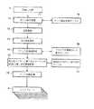
次に、図7を参照して、図6に示す画像処理部7の詳細について説明する。
【0061】
尚、以下に述べるプロセスは、ハード(画像処理ボード)で実行するように構成することもできるし、ソフトで実行するように構成することもできる。ソフトで実行する場合には、画像処理部7は存在せず、制御プログラム群の中に画像処理プログラムを格納し、CPUの制御により、このプログラムが実行されることで以下のプロセスが実行される。
【0062】
ガンマ補正処理工程11では、画像入力部1で入力される画像データCVを、予め用意されたガンマ補正変換テーブル4aを用いて濃度を表す濃度データCD(階調値)に変換し、イメージメモリ6に格納する。この実施形態では、CD値のレベル分けを、12bitとしている。
【0063】
前段処理工程12では、イメージメモリの画像に対し、拡大補間処理、画像回転、フォーマッティングなどの処理を行なう。注目画素選択工程13では、イメージメモリ領域内のこれから処理をしようとする一画素(対象画素)を選択し、濃度データCDを得る。
【0064】
ブロック内番地参照工程14では、ブロック内番地指定テーブル4bを参照して、処理しようとする注目画素がブロック内の何番地であるかのデータを得る。
【0065】
重ね打ちパターン振り分けテーブル4cの該当CD値及び番地参照工程15では、該注目画素(対象画素)のCD値に対応する重ね打ちパターン振り分けテーブル4cを参照し、この重ね打ちパターン振り分けテーブル、注目画素のCD値及び注目画素の番地データを参照して該注目画素(対象画素)のインク組み合せを得る。
【0066】
インク分配処理工程16では、上述のように得られたインク組み合せに従い、各濃度のインクの吐出、不吐出の2値信号を決定し、更にこれを所定の規則により、各ヘッドの吐出、不吐出の2値信号を決定して、各ヘッド毎のビットプレーンに記録する。
【0067】
以上の処理を行うことにより、注目した一画素の処理が終了する。
【0068】
画像の濃度データCDをもとに、前記14、15、16の処理をある領域分の全画素数繰り返すことにより、異なる濃度を持つそれぞれのヘッドに対する各画素ごとの吐出、不吐出の2値信号d1,d2,d3,…が形成される。
【0069】
ここで、上記領域は、記録しようとする1ページ全領域とし、1ページ分のビットプレーンを完成させてから以下に記す記録のプロセスに移行しても良いし、1ページを何分の一かに分割し、分割した領域ごとにビットプレーンを完成させ、まずこの領域の記録を行なったのち、次の領域の処理に移っても良い。後者の場合、それぞれのビットプレーンを更に複数に分け、前の領域の記録プロセスを行なっている間に次の領域のビットプレーンを作成するようにしても良い。
【0070】
記録を行う場合には、図2で、不図示の手段によりシート501が図の左方向からローラ502,503の間に送り込まれる。ついでシートは、モータ507により、所定距離ずつ間欠的にX方向に送られる。シートが停止している間に、モータ521が回転し、キャリッジをY方向に一定の速度で移動させる。キャリッジ上のヘッドが、シートの上を通過する間に、図6,図7の記録制御手段により、画像信号に対応したノズル吐出指令信号が送られ、これに従って各ノズルから選択的に液滴が吐出される。ヘッドがシート上を通過して、シート上から離れた位置にある間にモータ507がシートを所定距離X方向に移動して停止し、ここで再びモーター507がシートを所定スピードで移動させ、同様に選択的に液滴を吐出させる。以下これを繰り返すことで、最終的にシート上に所望の画像が記録される。記録が終了したシートは、504,506にて図2の左方向に搬送され、ついで不図示の搬送手段で図2の左方向に排出される。
[各種テーブルの一例]
次に、記憶媒体4に格納されている各種テーブルについて、例をあげて説明する。
【0071】
図8は、1ページの画像をブロックに分けたものを示す図で、a1,a2,a3,…,b1,b2,b3,…,c1,c2,c3…,がブロックを示す。
【0072】
図9(a)〜(e)は、一つのブロックの画素構成の例で、(a),(b),(c),(d),(e)の順に、横×縦が、2×1、1×2、2×2、4×4、変則2×4の例を示す。図9(e)のように、必ずしも矩形でなくとも良い。図9(a)〜(e)で、A1,A2,A3,…は、ブロック内の画素に付けられた番地を示す。図のように、一定の規則により配列しても良いし、ランダムに配列しても良い。また、全てのブロックを同じ配列にしても良いし、ブロック毎に変えても良い。これらの規則をテーブルに表したものが、ブロック内番地指定テーブルである。テーブルを設ける代わりに、あるアルゴリズムを与え、これにより各画素の番地をきめても良い。以下の説明は、4×4の例で行なう。
【0073】
各画素の大きさは、さまざまなものがあるが、以下の説明では、600dpiとする。この場合、ブロックの大きさは2×2単位だと300dpi相当、4×4単位だと150dpi相当となる。
【0074】
図10A及び10Bは、重ね打ちパターン振り分けテーブルの一例である。CD値の欄に縦に並んでいる数字は、CD値を示す。横に並んでいるA1〜A16は、図9(d)のように構成されたブロック内における各画素の番地を示す。ブロック番地の下の数字のうち、網掛けでない部分の各CD値ごとに4つずつ縦に並んでいる数字は、該当CD値の該当ブロック番地に対して重ね打ちされるインクの種類名を示している。×は打たないことを意味する。ここでは、一つの画素に対して、4つまで重ね打ちできる場合を示している。この例では、インクの種類名は、#1〜#8の8種類であり、これらの記録OD値は0.012、0.024、0.048、0.096、0.144、0.192、0.384、0.768である。この例では、各画素の記録OD値は、重ね打ちされた記録OD値の合計で示される、いわゆる加成性が成り立つものとしている。また、この例では、各ヘッドから吐出されるインク量が実質的に同一の場合の例を述べる。インク量が可変の場合は、例えば0.048のインクが2単位量吐出される場合は、記録OD値が0.096になると考え、以下の説明を適用できる。A1〜A16の下の網掛けの数字は、その下に記されているインクの記録OD値の合計である。尚、この合計値は、説明のためだけであり、実際のテーブルには設ける必要はない。α1〜α4は、図9(d)のブロック内での、2×2のサブブロックである。すなわち、α1は第1サブブロック(A1,A5,A9,A13)、α2は第2サブブロック(A2,A6,A10,A14)、α3は第3サブブロック(A3,A7,A11,A15)、α4は第4サブブロック(A4,A8,A12,A16)を示し、下の数字は、各サブブロックを構成する画素の記録OD値の平均を示す。尚、サブブロックα1〜α4は必ずしも設けなくてもよい。
【0075】
ここで、CD=0(64のインクをすべての番地に4回づつ打つ)から、CD=4095(すべての番地にインクを打たない)まで、4096のCD値に対してテーブルが用意されている。(異なる組み合せは4096より少ないので、いくつかのCD値に対しては、A1〜A16番地までの使用インクの組み合せは同じになることがあるが、この場合にはCD値が異なっても、同じ記録OD値に打たれる)
以上の構成により、図7の重ね打ちパターン振り分けテーブルの該当CD値及び番地参照工程15において、処理中の注目画素のCD値、注目画素のブロック内番地及び図10A及び10Bのテーブルから、該当注目画素に対して重ね打ちすべきインクの組み合せを決定する。
【0076】
尚、図10A及び10Bのテーブルを以下のように、2つに別けても良い。すなわち、4回の重ね打ちをする各種インクの組み合せを1つのテーブルに作成し、それぞれの組み合せに名前をつける。そして、図10A及び10Bのテーブルは、各番地に、重ね打ちするインク名を記入するかわりに、上の組み合せ名を記入しておく。そして、該当画素のCD値と番地に対応して、この組み合せで重ね打ちを行なう。このように、テーブルを2つに分けることで、全体のテーブルのボリュームを減らすことができ、メモリの節約になる。
【0077】
上のテーブルで、各番地に配置する記録OD値のならべ方は、いろいろ考えられるが、例えば、a個の画素(A1,A2,…,Aa)の記録OD値DA1,DA2,…,DAaが、DA1≧DA2≧DA3≧…≧DAaとなるように並べる方法がある。これは設計する際に、わかりやすい。そして、a個の画素(DA1,A2,…,Aa)の配列を、図9(d)に示すように、番地の隣り合う画素は、隣接しないように配列すると、所望OD値が上がる(または下がる)場合に、ブロックの中で偏らずに、記録OD値が上がる(又は下がる)ようにすることができる。このようにすることによって、所望OD値が上がる(又は下がる)場合に、見た目にざらつきが少なく、なめらかに変化とて見えるようになる。
[多階調記録の原理]
次に、以上の構成と手順により、多階調記録が可能な理由を説明する。
【0078】
図10Bによれば、ある1つのブロック内の全画素が同じCD値、例えばCD=4092を示すとすると、このブロック内には、記録OD値0.012のインクが3回打ち込まれることになる。面積階調の原理によれば、このブロックの記録OD値は、A1〜A16までの各画素の記録OD値の平均となる。つまりブロックの記録OD値は、0.012×3/16となる。また、別の1つのブロック内の全画素がCD=4091を示すとすると、同様にそのブロックの記録OD値は0.012×4/16となる。0.012〜0.768の記録OD値のインクを4回まで使用可能なので、CD=0では記録OD値の平均は3.07(=最も濃いインクの記録OD値0.768×重ね打ちできる回数4)となる。よって、0.012/16刻みで0〜3.07まで、すなわち、4096段階(途中いくつかのCD値に対して同じ記録OD値に打たれる部分があるので、実際にはこれより若干少ない)の表現が可能になる。
【0079】
次に、第1サブブロックの画素がすべてCD=4092、第2サブブロックの画素が全てCD=4088である場合、図10Bによれば、第1サブブロック内のA1画素に対して記録OD値0.012のインクが1回使用され、第2サブブロック内のA2及びA6画素に対して記録OD値0.012のインクが2回使用されるので、結局のところ、第1サブブロックには記録OD値0.012のインクが1回、第2サブブロックには記録OD値0.012のインクが2回使用されることになる。すなわち、サブブロック単位では、おおむねCD値の差が4あれば、平均記録OD値が異なる。すなわち、サブブロック単位では、約1000階調の表現が可能である。同様に、各画素単位では、約256階調の表現が可能である。(いずれも、途中いくつかのCD値に対して同じ記録OD値に打たれる部分があるので、実際にはこれより若干少ない。)
[擬似輪郭対策]
次に、本発明により、擬似輪郭が消失する理由を説明する。ここでは、CD値が3043付近の例で説明するが、他の部分でも同様である。図10A及び10Bのテーブルで、CD値3043とCD値3044とを比較すると、16画素の中で、A7画素に対して打ち込むべきインクの組み合わせだけが異なっている。具体的には、♯7のインクの打ち込み回数が1回だけ増加し、#6のインクの打ち込み回数が2回減少している。仮に♯6のインクによる記録OD値が設計値通り、♯7のインクによる記録OD値が誤差3%だとすると、この16画素での平均の誤差は、0.384×0.03/16=0.00072となる。これは既に説明した人間の目の分解能(濃度差=0.003)よりも小さい値であり、輪郭としては認識されない。すなわち、擬似輪郭は発生しない。もちろん、例えばCD値3044から3039に急変する場所では、#7のインクの打ち込み回数が5回増加、#6のインクの打ち込み回数が10回減少しているので、上記と同じ誤差を仮定すると、誤差は0.384×0.03×5/16=0.0036となるが、このような場所ではもともと輪郭が見えるので、問題にならない。
【0080】
更に加えると、本発明者らは、階調がなだらかに変化する画像を記録する際に、従来のように濃度の異なる画素に一度に切り換えるのではなく、濃度の異なる画素を使用する比率を段階的に上昇させることにより、擬似輪郭として認識されにくくなることを見出した。
【0081】
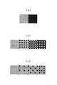
図23は、濃度が1段階濃い画素に切り換わるパターンの例を示している。図23(a)のパターンは、従来から用いられているパターンであり、低い濃度の画素から1段濃い画素に一斉に切り換わる。このパターンでは、上述のように、図中点線で示した境界部分が輪郭として認識できない濃度差の上限が0.003である。
【0082】
一方、図23(b)のパターンは、1段濃い濃度の画素を使用する比率を、1/4,2/4,3/4,4/4の4つのステップで段階的に徐々に上昇させる。このパターンでは、図中点線で示した境界部分が輪郭として認識できない濃度差の上限は0.015である。
【0083】
また、図23(c)のパターンは、1段濃い濃度の画素を使用する比率を、1/16,2/16,…,16/16の16のステップで段階的に徐々に上昇させる。このパターンでは、図中点線で示した境界部分が輪郭として認識できない濃度差の上限は0.03である。
【0084】
このように、濃度の異なる画素の使用比率を段階的に上昇させることにより、境界の輪郭が見えにくくなる。
【0085】
従って、濃度が滑らかに変化する場合に、図23(c)のパターンで変化するように画素の出現パターンをコントロールすることで、最小濃度差が0.03以下であれば擬似輪郭を見えないようにできる。また、図23(b)のパターンで変化するように画素の出現パターンをコントロールすることで、最小濃度差が0.015以下で擬似輪郭を見えないようにできる。
【0086】
このことを換言すると、次のようになる。即ち、図23(b)のパターンは、濃度が滑らかに変化(階調値が1増加)する場合に、1段濃い濃度の画素が出現する確率が1/4ということである。また、図23(c)のパターンは、濃度が滑らかに変化(階調値が1増加)する場合に、1段濃い濃度の画素が出現する確率が1/16ということである。
【0087】
このように、濃度が滑らかに変化(階調値が1増加)する場合に、1段濃い濃度の画素が出現する確率をコントロールすることにより、擬似輪郭を見えないようにすることができる。
【0088】
尚、図10A及び10Bのテーブル作成については、目的に応じていろいろな方法が考えられる。4×4のブロック単位での階調をできるだけ多くするためには、ブロック内の各番地の画素の記録OD値の差を無視しても、いくつかのCD値に対して同じ記録OD値に打たれる部分を少なくし、平均記録OD値の段階をできるだけ多くする方が良い。2×2のサブブロック単位での階調をできるだけ多くするためには、ブロック内の各番地の画素の記録OD値の差は無視するが、一つのブロック内にあるサブブロックの平均記録OD値ができるだけ均一になるようにすると良い。また、できるだけ画像のざらつきを押さえるためには、階調の段階数を犠牲にしても、一つのブロック内の各画素の記録OD値をできるだけ近づけるのが良い。
[第2実施形態]
第2実施形態について、図11,図12,図13を参照して説明する。
【0089】
第2実施形態では、インクの種類は#1〜#7の7種類であり、その記録OD値は0.024、0.048、0.096、0.144、0.192、0.384、0.768である。7種類としたのは、説明の都合だけで、第1実施形態と同様、8種類でも良い。図11は、概略、図10A及び10Bと同じ構成であるが、CD値の代わりに記録OD値の欄を設け、A1からA16までの各画素の記録OD値の平均が記入されている。図12は、CD値と図11の記録OD値とを対応させるテーブルで、0〜4095のCD値に対して、それを表現するのに最適な記録OD値が図11の記録OD値のうちから選択されて記入されている。図13は、図7に対応する図で、図7と一部のみ異なっている。
【0090】
この例では、図13の重ね打ちパターン振り分けテーブルの該当CD値、該当番地参照15において、注目画素のCD値から、図12のCD値対記録OD値対応テーブルにより、記録OD値を決め、さらに図11のテーブルによりその記録OD値の行から該当番地の画素に対応する重ね打ちパターンを決定する。
【0091】
この方法によると、テーブルは一つ増えるが、テーブルの全体量を減らすことができ、メモリの節約になる。なお、濃淡記録を行なうことで形成される記録媒体上の濃度と前記濃度データとの対応関係を得るための手段として、図12のテーブルを設ける代わりに、CD値と記録OD値を対応させるアルゴリズム(例えば計算式)を用意し、これに従って対応させても良い。
【0092】
さらにこの方法によると、後述の第3実施形態のように、記録OD値を補正することができる。
[第3実施形態]
第3実施形態について、図14(a),(b),図15,図16を参照して説明する。
【0093】
第1実施形態では加成性を前提にしている。我々の実験によると、透過メディアではほぼ加成性が成立するが、反射メディアの場合には加成性は成立しない。また、透過メディアでも、記録OD値が濃くなると、厳密には加成性が成り立たない。このような場合にも、以下のような補正方法を導入すれば、本発明が適用できる。
【0094】
すなわち、加成性が成立する仮想記録OD値(インク値)を想定し、実際の記録OD値とこのインク値とをグラフや関係式で対応づける。そして、インクを重ね打ちする場合には、まず、重ね打ちするインクの記録OD値から、前記対応によって、インク値を求め、重ね打ちするインクのインク値を合計する。ついで、再度前記対応により、重ね打ちした画素の記録OD値を求める。図14(a),(b)は、このような例のグラフである。横軸xはインク値に比例する値(反射メディアでは#8のインク値を1に換算した数字、透過メディアでは#8のインク値を32に換算した数字になっている)、縦軸yがOD値である。(a)が各種反射メディアについての結果、(b)が各種透過メディアについての結果である。インク値は、CD値に比例するから、図14(a),(b)に記入すると、直線で表される。記録OD値は、低濃度領域では、インク値とほぼ同じであるが、濃度があがるにつれてずれてくる。このような曲線は一般的にxの多項式で近似できる。一例として、透過メディアの場合で、y=ax+bx2+cx3+dx4と近似し、定数を求めたところ、a=0.94256、b=−0.14854、c=0.047632、d=−0.0062243が記録OD値に良い近似を与えることがわかった。
【0095】
尚、この例では、インクは#1〜#8まで8種類使用するが、そのインク値が、0.012、0.024、0.048、0.096、0.144、0.192、0.384、0.768になるようにしている。図15は、図11に対応するテーブルである。この例では、一部1画素に対して5回重ね打ち可能としている。図15で、各階調、各番地毎に、重ね打ちされるインク値の合計を求め、この値をxとして上の式を用いて補正した値yを、網掛け部分に記入してある。記録OD値の欄の数字は、右16画素の記録OD値の平均値である。図16は、図12に対応するテーブルで、各CD値に対し、図15のテーブルの中から、使用する行の記録OD値が記入してある。
【0096】
反射メディアの場合も、上の式で、適切な係数を求めれば、同様に補正が可能であり、この補正式を用いて、同様に記録することができる。
[第4実施形態]
第4実施形態について、図17(a)〜(c),図18A及び18Bを参照して説明する。
【0097】
図17(a)〜(c)は、図8に対応する図で、4×4のブロックがA,Bの2種類あり、これらが、図17(c)のように配置されている。図18A及び18Bは、図10A及び10Bに対応する図で、図10A及び10Bと同様のテーブルで、ブロックAとブロックBがそれぞれ設けられている。β1〜β4は、ブロックB内での、2×2のサブブロックである。すなわち、β1は第1サブブロック(B1,B5,B9,B13)、β2は第2サブブロック(B2,B6,B10,B14)、β3は第3サブブロック(B3,B7,B11,B15)、β4は第4サブブロック(B4,B8,B12,B16)を示し、下の数字は、各サブブロックを構成する画素の記録OD値の平均を示す。尚、サブブロックβ1〜β4は必ずしも設けなくてもよい。
【0098】
ブロックAのテーブルとブロックBのテーブルは、略同じであるが、一部のみ異なっている(網かけ部分)。この例では、CD値の変化に対して、インクの切り替わりの割合がさらに少なくなっている。すなわち、図10A及び10Bでは、CD値の1の変化に対して、#7のインクの使用個数がブロック内で1個ずつ変化しているが、図18A及び18Bでは、CD値の1の変化に対して、#7のインクの使用個数が、ブロックA、ブロックBで交互に1個ずつ変化しており、その変化割合は1/2になっている。このため、ブロックAとブロックBをあわせた平均記録OD値で考えると、所望OD値と記録OD値の誤差は、前述の仮定のもとで、0.384×0.03/(16×2)=0.00036となり、図10A及び10Bの例よりもさらに小さくなる。
【0099】
ブロックの数は、2種類に限らず、例えば4種類、9種類などにすることもでき、その場合は、更に所望OD値と平均記録OD値の誤差を小さくできる。第4実施形態によれば、#8のインクのように濃いインクの場合や、インクの記録OD値変動が更に大きい場合に有効である。
[他の手段]
インクジェットの方式については、特に制限はない。本実施形態では、液体のインクを用いる例を述べたが、固形のインクを溶かして吐出するものでもよい。この場合は、インクの補給は固形インクを交換することになる。シートは反射、透過いずれでもよい。
【0100】
シートを間欠送りさせ、シートが停止している間にシート送り方向と直交する方向にヘッドを移動させて記録する本実施形態に止まらず、シートを定速で送り、シートの送り方向と直交する方向にシート幅をカバーするようにライン状の固定ヘッドを設け、シートが定速で送られる間に記録を行う方式でも良い。この場合は、それぞれ異なるインクについてシートの幅をカバーする長さのヘッドを装着しておく。
【0101】
インクの供給方式は、図1のようなカートリッジ方式に限らない。キャリッジ上とは別にインクタンクを設け、インクタンクからチューブでヘッドにインクを供給する方式でも良い。
【0102】
また、使用量の多いインクのみチューブ供給とし、それ以外はカートリッジ方式としても良い。
【0103】
なお、以上の実施形態において、記録ヘッドから吐出される液滴はインクであるとして説明し、さらにインクタンクに収容される液体はインクであるとして説明したが、その収容物はインクに限定されるものではない。例えば、記録画像の定着性や耐水性を高めたり、その画像品質を高めたりするために記録媒体に対して吐出される処理液のようなものがインクタンクに収容されていても良い。
【0104】
以上の実施形態は、特にインクジェット記録方式の中でも、インク吐出を行わせるために利用されるエネルギーとして熱エネルギーを発生する手段(例えば電気熱変換体やレーザ光等)を備え、前記熱エネルギーによりインクの状態変化を生起させる方式を用いることにより記録の高密度化、高精細化が達成できる。
【0105】
その代表的な構成や原理については、例えば、米国特許第4723129号明細書、同第4740796号明細書に開示されている基本的な原理を用いて行うものが好ましい。この方式はいわゆるオンデマンド型、コンティニュアス型のいずれにも適用可能であるが、特に、オンデマンド型の場合には、液体(インク)が保持されているシートや液路に対応して配置されている電気熱変換体に、記録情報に対応していて核沸騰を越える急速な温度上昇を与える少なくとも1つの駆動信号を印加することによって、電気熱変換体に熱エネルギーを発生せしめ、記録ヘッドの熱作用面に膜沸騰を生じさせて、結果的にこの駆動信号に1対1で対応した液体(インク)内の気泡を形成できるので有効である。この気泡の成長、収縮により吐出用開口を介して液体(インク)を吐出させて、少なくとも1つの滴を形成する。この駆動信号をパルス形状をすると、即時適切に気泡の成長収縮が行われるので、特に応答性に優れた液体(インク)の吐出が達成でき、より好ましい。
【0106】
このパルス形状の駆動信号としては、米国特許第4463359号明細書、同第4345262号明細書に記載されているようなものが適している。なお、上記熱作用面の温度上昇率に関する発明の米国特許第4313124号明細書に記載されている条件を採用すると、さらに優れた記録を行うことができる。
【0107】
記録ヘッドの構成としては、上述の各明細書に開示されているような吐出口、液路、電気熱変換体の組み合わせ構成(直線状液流路または直角液流路)の他に熱作用面が屈曲する領域に配置されている構成を開示する米国特許第4558333号明細書、米国特許第4459600号明細書を用いた構成も本発明に含まれるものである。加えて、複数の電気熱変換体に対して、共通するスロットを電気熱変換体の吐出部とする構成を開示する特開昭59−123670号公報や熱エネルギーの圧力波を吸収する開口を吐出部に対応させる構成を開示する特開昭59−138461号公報に基づいた構成としても良い。
【0108】
さらに、記録装置が記録できる最大記録媒体の幅に対応した長さを有するフルラインタイプの記録ヘッドとしては、上述した明細書に開示されているような複数記録ヘッドの組み合わせによってその長さを満たす構成や、一体的に形成された1個の記録ヘッドとしての構成のいずれでもよい。
【0109】
加えて、上記の実施形態で説明した記録ヘッド自体に一体的にインクタンクが設けられたカートリッジタイプの記録ヘッドのみならず、装置本体に装着されることで、装置本体との電気的な接続や装置本体からのインクの供給が可能になる交換自在のチップタイプの記録ヘッドを用いてもよい。
【0110】
また、以上説明した記録装置の構成に、記録ヘッドに対する回復手段、予備的な手段等を付加することは記録動作を一層安定にできるので好ましいものである。これらを具体的に挙げれば、記録ヘッドに対してのキャッピング手段、クリーニング手段、加圧あるいは吸引手段、電気熱変換体あるいはこれとは別の加熱素子あるいはこれらの組み合わせによる予備加熱手段などがある。また、記録とは別の吐出を行う予備吐出モードを備えることも安定した記録を行うために有効である。
【0111】
さらに、記録装置の記録モードとしては黒色等の主流色のみの記録モードだけではなく、記録ヘッドを一体的に構成するか複数個の組み合わせによってでも良いが、異なる色の複色カラー、または混色によるフルカラーの少なくとも1つを備えた装置とすることもできる。
【0112】
以上説明した実施の形態においては、インクが液体であることを前提として説明しているが、室温やそれ以下で固化するインクであっても、室温で軟化もしくは液化するものを用いても良く、あるいはインクジェット方式ではインク自体を30°C以上70°C以下の範囲内で温度調整を行ってインクの粘性を安定吐出範囲にあるように温度制御するものが一般的であるから、使用記録信号付与時にインクが液状をなすものであればよい。
【0113】
加えて、積極的に熱エネルギーによる昇温をインクの固形状態から液体状態への状態変化のエネルギーとして使用せしめることで積極的に防止するため、またはインクの蒸発を防止するため、放置状態で固化し加熱によって液化するインクを用いても良い。いずれにしても熱エネルギーの記録信号に応じた付与によってインクが液化し、液状インクが吐出されるものや、記録媒体に到達する時点では既に固化し始めるもの等のような、熱エネルギーの付与によって初めて液化する性質のインクを使用する場合も本発明は適用可能である。このような場合インクは、特開昭54−56847号公報あるいは特開昭60−71260号公報に記載されるような、多孔質シート凹部または貫通孔に液状または固形物として保持された状態で、電気熱変換体に対して対向するような形態としてもよい。本発明においては、上述した各インクに対して最も有効なものは、上述した膜沸騰方式を実行するものである。
【0114】
さらに加えて、本発明に係る記録装置の形態としては、コンピュータ等の情報処理機器の画像出力端末として一体または別体に設けられるものの他、リーダ等と組み合わせた複写装置、さらには送受信機能を有するファクシミリ装置の形態を取るものであっても良い。
【他の実施形態】
なお、本発明は、複数の機器(例えばホストコンピュータ、インタフェイス機器、リーダ、プリンタなど)から構成されるシステムに適用しても、一つの機器からなる装置(例えば、複写機、ファクシミリ装置など)に適用してもよい。
【0115】
また、本発明の目的は、前述した実施形態の機能を実現するソフトウェアのプログラムコードを記録した記憶媒体(または記録媒体)を、システムあるいは装置に供給し、そのシステムあるいは装置のコンピュータ(またはCPUやMPU)が記憶媒体に格納されたプログラムコードを読み出し実行することによっても、達成されることは言うまでもない。この場合、記憶媒体から読み出されたプログラムコード自体が前述した実施形態の機能を実現することになり、そのプログラムコードを記憶した記憶媒体は本発明を構成することになる。また、コンピュータが読み出したプログラムコードを実行することにより、前述した実施形態の機能が実現されるだけでなく、そのプログラムコードの指示に基づき、コンピュータ上で稼働しているオペレーティングシステム(OS)などが実際の処理の一部または全部を行い、その処理によって前述した実施形態の機能が実現される場合も含まれることは言うまでもない。
【0116】
さらに、記憶媒体から読み出されたプログラムコードが、コンピュータに挿入された機能拡張カードやコンピュータに接続された機能拡張ユニットに備わるメモリに書込まれた後、そのプログラムコードの指示に基づき、その機能拡張カードや機能拡張ユニットに備わるCPUなどが実際の処理の一部または全部を行い、その処理によって前述した実施形態の機能が実現される場合も含まれることは言うまでもない。
【0117】
本発明を上記記憶媒体に適用する場合、その記憶媒体には、先に説明した図7に示すフローチャートに対応するプログラムコード及び各種テーブルが格納されることになる。
【0118】
以上のように、本実施形態のようなテーブルを用いることで、画像特性を自由にコントロールすることができ、特に、実施形態として説明したように、CD値の変化に対する各インクの出現頻度をコントロールすることができる。すなわち、CD値の変化に対して、各インクの(特に濃いインクの)出現頻度を滑らかに変化させることにより、所望OD値と記録OD値の誤差があっても、擬似輪郭のない画像を得ることができる。
【0119】
誤差拡散処理でも、拡散の係数を変えることで、ある程度CD値の変化に対する各インクの出現頻度が変わるが、本実施形態のように、きめ細かく、しかも、全てのCD値にわたって自由に設定することはできない。
【0120】
誤差拡散では、誤差拡散処理時、計算が必要になるが、この例では、テーブルを参照するだけなので、処理時間が少なくて良い。各画素(600dpi)で表現できる階調数が誤差拡散と同じ場合には、誤差拡散の方が滑らかな画像が得られるが、本実施形態では、上述のように、処理時間が短くできるので、その分各表現できる階調数を増やすことができる。例えば、特開平10−324002号公報では、濃淡インクの種類を6種類、各画素で表現できる濃度は50種類程度であるが、上記実施形態では、濃淡インクの種類を8種類とし、各画素(600dpi)で表現できる濃度を256階調としている。この結果、画素2×2単位(300dpi)では、1000階調、画素4×4単位(150dpi)では、4000階調の表現を可能としている。この方法により、実際に胸部X線画像を記録したところ、擬似輪郭は軽減された。
【0121】
【発明の効果】
以上説明したように、本発明によれば、記録画像の用途等に応じて出力特性を容易に変更可能で、高画質の画像を高速に記録できる。
【図面の簡単な説明】
【図1】本発明に係る実施形態のインクジェット記録装置の要部(記録部)を示す斜視図である。
【図2】図1をA方向から見た側面図である。
【図3】キャリッジを上方向から見た部分詳細図である。
【図4】(a)は、はヘッドを図1の下側から見た部分詳細図、(b)はシートにインクが打ち込まれた状態を示す図である。
【図5】キャリッジを下から見た部分詳細図である。
【図6】記録制御手段のブロック図である。
【図7】画像処理部のブロック図である。
【図8】画素をブロックに分割する例を示す図である。
【図9】ブロック番地指定テーブルの例を示す図である。
【図10A】第1実施形態の重ね打ちパターン振り分けテーブルを示す図である。
【図10B】第1実施形態の重ね打ちパターン振り分けテーブルを示す図である。
【図11】第2実施形態の重ね打ちパターン振り分けテーブルを示す図である。
【図12】CD値と図11の記録OD値とを対応させるテーブルを示す図である。
【図13】第2実施形態の画像処理部のブロック図である。
【図14】インク値対濃度のグラフである。
【図15】第3実施形態の重ね打ちパターン振り分けテーブルを示す図である。
【図16】CD値と図15の記録OD値とを対応させるテーブルを示す図である。
【図17】第4実施形態として画素を2ブロックに分割する例を示す図である。
【図18A】第4実施形態の重ね打ちパターン振り分けテーブルを示す図である。
【図18B】第4実施形態の重ね打ちパターン振り分けテーブルを示す図である。
【図19】入力画像データ(4096階調)を53値化して画像を出力する時の各階調(53階調)を表現するためのインクの種類とその組み合せのテーブルを示す図である。
【図20】従来のインクジェット記録装置の記録制御の手順を示すフローチャートである。
【図21】従来の入力画像データと多値誤差拡散処理後に得られる53値化画像データの配置を示す模式図である。
【図22】従来の方法により透明フィルム上に胸部X線画像を記録した例を示し、擬似輪郭の説明図である。
【図23】擬似輪郭の低減方法を説明する図である。
【符号の説明】
501 シート
512 キャリッジ
513a〜513r 記録ヘッド
514 ノズル
526a〜526r インクカートリッジ
1 画像入力部
2 操作部
3 CPU
4 記憶媒体
4a ガンマ補正変換テーブル
4b ブロック番地指定テーブル
4c 重ね打ちパターン振り分けテーブル
4d CD値対記録OD値対応テーブル
4e 制御プログラム群
5 RAM
6 イメージメモリ
7 画像処理部
8 ビットプレーンメモリ
9 プリンタ部
10 バスライン
20 画像
21 ブロック
22 画素
100 X線記録画像
101 擬似輪郭[0001]
BACKGROUND OF THE INVENTION
The present invention relates to a recording apparatus and a recording method, and more particularly to a recording apparatus and a recording method for recording an image with multiple gradations.
[0002]
[Prior art]
Among printers of various recording methods, there are printers that form text and images on a recording medium by attaching a recording agent to the recording medium. A typical example of such a recording method is an ink jet recording apparatus. In recent years, the performance of ink jet recording apparatuses has improved, and not only text but also images have been recorded.
[0003]
In an inkjet recording apparatus, a nozzle group in which a plurality of ink ejection ports (nozzles) capable of ejecting ink of the same color and the same density are integrated is used to improve the recording speed, and the nozzle groups are the same. In general, inks having different densities and different colors are provided. There are also inks that can discharge ink of the same color and the same density by changing the discharge amount in several stages.
[0004]
While the head provided with these nozzle groups is moved relative to the recording medium, ink is ejected from the nozzles to perform recording.
[0005]
As a method of moving the head relative to the recording medium,
(i) The nozzle groups are arranged substantially in parallel in the X direction, and while the recording medium is stopped, the recording head is moved in the direction (Y direction) perpendicular to the X direction, and recording is performed during this period. A so-called swath printing method in which a recording medium is intermittently moved by a predetermined distance in the X direction, and then the recording head is moved again in the Y direction.
(ii) A so-called full multi-print method in which the nozzle group is fixed so as to cover the entire width of the recording medium in the Y direction, and recording is performed while the recording medium is moved at a constant speed in the X direction.
Has been implemented.
[0006]
When an image is recorded by these methods, a pixel is defined as a unit constituting the image. A pixel is not necessarily composed of one dot (a portion formed on a recording medium by one ink ejection from one nozzle), and one pixel is formed by a plurality of dots. May be. In the case of forming with a plurality of dots, they may be recorded overlapping each other at substantially the same point, or may be recorded at adjacent points. In any case, it is determined according to a predetermined rule. The image data to be recorded is subjected to processing such as enlargement interpolation and reduction by an image processing means so as to obtain an image size suitable for the recording apparatus. Next, for each pixel, the color and density to be recorded are determined according to a predetermined rule, and recording is executed according to this determination. As described above, one pixel may be composed of a plurality of dots. In this case, inks having different densities can be selected without being limited to one density. In the case of using a discharge amount variable head, the discharge amount, that is, the dot ink amount may be appropriately changed. Moreover, you may combine these.
[0007]
When recording an image, a halftone processing method such as a dither method or an error diffusion method is performed as a method for faithfully reproducing the gradation of the image data. Furthermore, in the dither method and the error diffusion method, more gradations can be expressed by increasing the gradation of one pixel. A specific example of such a recording method is described in JP-A-10-32002.
[0008]
That is, for each color, nozzle groups capable of ejecting inks having different densities are prepared, and from these nozzle groups, recording is selectively performed a plurality of times within a predetermined limit with respect to one pixel (hereinafter referred to as a “color”). By performing overprinting), it is possible to increase the gradation of density (recording OD value) that can be expressed by this pixel. For example, if six types of nozzle groups capable of ejecting different concentrations of ink are prepared and one pixel of 600 dpi is overprinted four times or less, it is possible to express 50 gradations or more. If one pixel is composed of 2 × 2 points adjacent to each other and is composed of a total of up to 16 recordings, it is possible to express 200 gradations or more. Instead of preparing a nozzle group capable of ejecting inks having different densities, gradation may be expressed by varying the amount of ink ejected from the nozzles and varying the ink amount of dots. Further, gradation may be expressed by a combination of these.
[0009]
In these cases, a rule that correlates the density (desired OD value) of the pixel to be expressed and the method of ink overprinting is determined in advance, and actual recording is performed according to this rule, that is, ink is ejected at which nozzle and when. In accordance with this, recording is performed by the actual recording control means.
[0010]
As an example, the recording OD value of the pixel when recording with each ink is measured, and the recording OD value when overprinting is determined based on the measured value, and the recording OD value of the pixel for each overstrike pattern is determined. Prepare a table describing. Then, a pattern for overprinting the recording OD value close to the desired OD value of the pixel to be recorded is selected. In the case of error diffusion processing, the difference between the desired OD value of the pixel to be recorded and the recorded OD value of the table is obtained and assigned to the adjacent pixels as an error.
[0011]
[Problems to be solved by the invention]
Since there are various images in the world, the characteristics required for printers vary depending on the application and purpose. Desirably, it is preferable if the recording characteristics can be designed freely when designing various printers according to the intended use.
[0012]
An example of a medical image will be described as an example that requires special recording characteristics.
[0013]
In some fields such as medical images, many monochrome images recorded in monochrome are still used. This is because a monochrome image has a higher density resolution of human eyes, and therefore, in a field where a higher density resolution is required, a larger amount of information can be recognized by humans than a color image. Furthermore, it is known that the use of a transmission type recording medium as a recording medium increases the density resolution that can be recognized by humans. In general, the density resolution of the human eye for color images is said to be about 8 bits, whereas for monochrome transmission images, it is said to be 10 to 11 bits. Medical X-ray photographs and CT / MRI images recorded on transmission media are actually read up to the human density resolution limit and provide information for diagnosis. As a printer for recording such a high gradation monochrome image, a laser imager that irradiates a silver salt film with a laser beam modulated in accordance with an image signal and develops the film to obtain an image on the film. is there. In the case of such a laser imager, recording is often performed with a density resolution of 12 bits in consideration of a certain margin. However, such a laser imager is expensive, requires wet development processing, and has problems such as waste liquid processing and complicated maintenance. There is also a dry silver salt type laser imager that performs development processing by heating instead of performing wet development processing, but has a problem that the image quality is inferior to that of wet processing.
[0014]
On the other hand, as described in Japanese Patent Laid-Open No. 10-32002, there is an ink jet system capable of density gradation of 50 gradations or more at 600 dpi, and further performing error diffusion processing to record 256 gradations. Proposed. Japanese Patent Application Laid-Open No. 10-32002 discloses a recording example of 256 gradations. If the input image data has 4096 gradations instead of 256 gradations, 4096 gradations can be recorded.
[0015]
Here, the ink used in the recording head disclosed in Japanese Patent Laid-Open No. 10-32002 is shown in Table 1 below. As shown in Table 1, six types of ink are used, and A, B, C, D, E, and F are used in descending order of density. At the same time, the dye concentration (%) and transmission density of each of the inks A to F are shown. Each ink is composed of a dye and a solvent, and the solvent contains various additives such as a surfactant and a humectant. These additives control the ejection characteristics from the recording head and the absorption characteristics on the recording medium.
[0016]
[Table 1]
When using these inks and the maximum number of types of ink to be applied to the same pixel is 4, the number of gradations that can be represented by one pixel is 6 + 6C2 + 6C3 + 6C4 + 1 = 57. In Table 1, inks having dye concentrations that cannot be combined to have the same concentration are set. At this time, the density ratio of the four ink dots on the low density side alone is 1: 2: 4: 8 from the low density side, and an image using 53 gradations out of these 57 gradations is used. Is output. That is, as described above, the input image data (4096 gradations) is converted into 53 values and an image is output. FIG. 19 shows ink types and their combinations for expressing each gradation (53 gradations) at that time. In the figure, No. The column shows each gradation. The part indicated by * in the figure indicates a combination that is not used to make the difference in density level in the low density part smaller than that in the high density part. In the column of inks A to F, ◯ indicates that the ink is ejected from the recording head, and × indicates that the ink is not ejected from the recording head. Further, the column of d1 [i] (i = 0 to 52: integer) indicates the ink density level expressing each gradation. Further, a column of th [i] (i = 1 to 52: integer) indicates a threshold value for determining the input image data to any one of 53 gradations. Note that the threshold value is normally determined as the midpoint ink density level between the ink density level d1 [k−1] and the ink density level dl [k].
[0018]
Here, a combination of ink types indicating each gradation is combination data, and an ink density level determined based on the combination data is ink density data.
[0019]
Then, the multi-value error diffusion processing unit uses the 53-value ink density level (d1 [0] to d1 [57]) and the 52-value threshold value (th [1] to th [52]) in the input image. A multilevel error diffusion process for converting data (4096 gradations) into 53 values is performed. As described above, the multi-value error diffusion process described in the above publication has a plurality of threshold values for converting the input image data into multi-values, here, 52 values, and this point is greatly different from the normal error diffusion process. In this example, the multi-valued error diffusion process is used to multi-value the input image data. However, the present invention is not limited to this. For example, the input image data may be multi-valued using another multi-value method such as a multi-value average density storage method, a multi-value dither matrix method, or a sub-matrix method.
[0020]
Next, the recording control procedure of the ink jet recording apparatus described in the above publication will be described with reference to the flowchart of FIG.
[0021]
FIG. 20 is a flowchart showing a recording control procedure of the ink jet recording apparatus described in the above publication.
[0022]
First, in step S1, the ink density data / combination data section stores data relating to the ink used in the recording head including the ink density data and the combination data.
[0023]
Next, in step S2, input image data is input, and multilevel error diffusion processing is performed on each pixel indicated by the input image data.
[0024]
Here, details of the multilevel error diffusion processing will be described with reference to FIGS.
[0025]
FIGS. 21A and 21B are schematic diagrams showing the arrangement of the input image data described in the above publication and the 53-valued image data obtained after the multilevel error diffusion processing. That is, it is a diagram illustrating a part of pixel arrangement in 4096 density data (0 (black) to 4095 (transparent)) for each pixel indicated by input image data.
[0026]
In FIG. 21A, f (i, j) has a 4096 density data level of the target pixel (i, j) to be multi-valued (53-valued). In addition, each pixel f (i−2, j−1) to (i−1, j) above the broken line has already been subjected to multi-value (53-value) processing, and B (i, j) Are 53 values of density data (“0”, “137.6”,..., “4011.2”, “4080”) after the multi-value (53-value) of the pixel of interest (i, j). ). After the multi-value (53-value) of the target pixel (i, j), the same multi-value (53-value) processing is sequentially performed as f (i, j + 1), f (i, j + 2),. Do.
[0027]
First, the 4096 density data level f (i, j) of the target pixel (i, j) is compared with the threshold value th [k].
[0028]
th [k] ≦ f (i, j) <th [k + 1] (1)
B (i, j) = dl [k] (2)
Then, k satisfying the above equation (1) is obtained, and density data B (i, j) after multi-value (53-value) of the pixel of interest (i, j) is determined by equation (2).
[0029]
Subsequently, by using the error diffusion matrix shown in FIG. 21 (b), the density data B (i, j) determined by the multilevel processing and the 4096 density data level f (i, j) before the multilevel processing. The error err that occurs between (j) and (3) is calculated by the following equation (3).
[0030]
err = f (i, j) −dl [k] (3)
Then, the calculated error err is diffused to other pixels according to the following equation (4).
[0031]
f ′ (x, y) = f (x, y) + err × M (x−i, y−j) / 31 (4)
As described above, the error err is diffused to each pixel in accordance with the distribution of the error diffusion matrix as shown in FIG. 21B, and thereafter, the value f ′ (i, j) including the diffused error is used. Similarly, multi-value processing (53-value processing) is performed.
[0032]
In step S3, the data distribution unit performs ink for the print head based on the combination data shown in FIG. 19 described above corresponding to the density data B (i, j) obtained by the multi-value (53-value) process. Discharge control data is generated. For example, when the density data B (i, j) = 1036.8, ink discharge control data is generated so that ink A, ink C, ink D, and ink F are discharged.
[0033]
In step S4, the recording head / paper feed control unit controls the driving of the recording head and the conveyance of the recording medium according to the ink ejection control data, thereby forming a gradation image.
[0034]
In the above publication, a medical gradation image (transmission) is output using six inkjet heads (256 nozzle match heads) equivalent to 600 dpi.
[0035]
As described above, according to the prior art described in the above publication, a recording head capable of discharging a plurality of types of dark and light inks in the conveyance direction (sub-scanning direction) of the recording medium is provided, and when forming an image, the pixels are By performing recording by ejecting at least one ink dot to be formed, for example, the same recording head as that of a conventional recording head can be obtained without creating a new recording head capable of ejecting many types of ink to one recording head. The number of gradations of an image recorded with the configuration can be increased. That is, it is possible to obtain a good gradation image having a large number of gradations without at least a significant cost for creating a new recording head.
[0036]
When an X-ray image was actually recorded by this method (4096 gradations), good image quality was obtained. However, depending on the type of image, some image quality problems occur compared to the image quality of a laser imager. One example will be described below.
[0037]
FIG. 22 shows an example in which a chest X-ray image is recorded on a transparent film by this method, and 100 is the film. In a normal X-ray photograph, the density of the shoulder portion originally changed smoothly, but in this example, an
[0038]
As a result of analyzing why such a pseudo contour occurs, it has been found that the cause is as follows.
[0039]
Referring to FIG. 19 as an example, when considering a portion where the density gradation changes from 3043 to 2974, in this portion, the first No. 37 combinations are mainly used, followed by No. 37. 36 combinations are mainly used. No. 37 and no. When the combination of 36 is compared, no. In No. 37, inks C, D, E, and F are used. In FIG. 36, it can be seen that ink B is used, and the ink used is greatly changed.
[0040]
And No. No. 37 combination is used or no. Whether the combination of 36 is used is determined by the result of the error diffusion process, but generally, it is a portion where the gradation changes gently, and it does not always change gradually but changes suddenly.
[0041]
By the way, the ink is mixed so as to have a density as shown in Table 1, but an error actually occurs. Moreover, even if it is a correct value when it is blended, it slightly changes over time due to evaporation or the like. According to experiments, a change of 2 to 3% can usually occur, and in many cases, the change may be about 5%. Assuming that the density change is 3%, for example, for B ink, the transmission density is about 0.89 × 0.03 = 0.027. That is, the above-mentioned No. 37 to No. Even if the inks C, D, E, and F have the correct values at the transition of 36, if the B ink changes by 3%, it means that an error of 0.027 occurs in the transmission density. For example, if it is assumed that there is the above-mentioned transition in 50% of pixels in a certain minute region, an error of 0.0135 is generated in the average density of that region.
[0042]
On the other hand, the density resolution of the human eye is 10 bits or more for the transmission film, which is 0.003 when converted to the transmission density. Therefore, if there is a density difference of 0.003 or more, this is recognized as a contour. That is, even if there is originally no outline, if there is a density difference of 0.003 or more, it is recognized as an outline.
[0043]
With respect to this number 0.003, 0.0135, which is the above-described density error, is a sufficiently large number, and a pseudo contour easily appears due to this density error. Furthermore, the discharge amount varies depending on the nozzle. If it is evenly distributed, the number of nozzles is large, so that the overall variation is reduced due to the averaging effect. However, if the variation is uneven for each chip, this also appears as a density error.
[0044]
Another image quality problem is as follows.
[0045]
In the error diffusion method, when the desired OD value is smaller than the minimum recording OD value, the ink is not applied up to a certain threshold value, and the ink of the minimum recording OD value is applied only when the threshold value is reached. For this reason, a phenomenon (sweeping phenomenon) occurs in which the density gradually increases from the transparency and is transparent up to a certain point and suddenly increases from a certain point.
[0046]
In addition to the image quality problem, the error diffusion process has a problem that it takes a processing time because calculation is performed for each pixel every time an image to be recorded changes. In particular, many multiplications and divisions occur when an error is distributed to surrounding pixels. In order to improve the image quality, the number of pixels to be distributed increases the calculation. If the pixel size is reduced to 300 dpi or 600 dpi in order to cope with a high-definition image, the number of pixels is large and processing time is required. In particular, in the case of medical images, the above problems are serious because they are often recorded on a large film of 14 × 17 inches.
[0047]
In the above, an example is described in which an extremely high level of image quality is required, but the image quality is not so high, but if you want to record at high speed, you need a simple printer as much as possible and an inexpensive printer that can record high image quality. There is also.
[0048]
The present invention has been made in view of the above-described problems, and an object thereof is to provide a recording apparatus and a recording method capable of easily changing output characteristics according to the use of a recorded image and the like and recording a high-quality image at high speed. That is.
[0049]
[Means for Solving the Problems]
In order to solve the above-described problems and achieve the object, the recording apparatus of the present invention has a plurality of types of different colors with the same color system.ink Thevomit Recording headAnd discharging the plurality of types of ink so as to overlap the pixels on the recording medium based on the density information values of the pixels constituting the image data. ,Discharged Multiple speciesink Expressed by a combination ofHave concentration A recording apparatus for recording an image including pixels, each of the density information values in a plurality of stages, SaidConfigure each block by dividing image data into multiple blocks Multiple pixelsAbout each ofIn the block Address information indicating the positionWhen SaidInk to be ejected to the pixel Combination information representing a combination ofWhen A data storage unit that stores data corresponding to each other, and the data stored in the data storage unit based on the density information value and address information of the target pixel, and the target pixelInk to be ejected Acquisition means for acquiring the combination information, and acquired by the acquisition meansAbove From the recording head to the target pixel based on combination informationink Thevomit A plurality of levels of density information values indicated by the data stored in the data storage unit, the same density information value is different for one address information and another address information.ink Representing different combinations ofAbove Combination information corresponds.
[0050]
In addition, the recording method of the present invention provides a plurality of types of different colors with the same color system.ink Thevomit Recording headAnd discharging the plurality of types of ink so as to overlap the pixels on the recording medium based on the density information values of the pixels constituting the image data. ,Discharged Multiple speciesink Expressed by a combination ofHave concentration A recording method for recording an image including pixels, wherein each of the density information values in a plurality of stages, SaidConfigure each block by dividing image data into multiple blocks Multiple pixelsEach SaidIn block Address information indicating the positionWhen SaidInk to be ejected to the pixel Combination information representing a combination ofWhen The target pixel based on the density information value and the address information of the target pixel.Ink to be ejected The acquisition step of acquiring the combination information, and acquired in the acquisition stepAbove From the recording head to the target pixel based on combination informationink Thevomit Of the plurality of levels of density information indicated by the data stored in the data storage unit, the same density information value is different for one address information and another address information.ink Representing different combinations ofAbove Combination information corresponds.
[0051]
DETAILED DESCRIPTION OF THE INVENTION
FIG. 1 is a perspective view showing a main part (recording unit) of an ink jet recording apparatus according to an embodiment of the present invention, FIG. 2 is a side view of FIG. 1 viewed from the direction A, and FIG. 4A is a partial detailed view of the head as viewed from the lower side of FIG. 1, FIG. 4B is a view showing a state in which ink is applied to the sheet, and FIG. 5 is a view of the carriage from the lower side. FIG.
[0052]
As shown in FIGS. 1 to 5,
[0053]
FIG. 6 is a block diagram of the recording control means.
[0054]
As shown in FIG. 6,
[0055]
[0056]
In the storage medium (data storage unit) 4, 4 a is a gamma correction conversion table for reference in gamma conversion processing, 4 b is a block internal address (4 × 4) designation table described later, 4 c is an overlapping pattern distribution table described later, 4 d Indicates a CD value-to-recorded OD value correspondence table, which will be described later, and 4e indicates a program group storing various programs.
[0057]
[0058]
An
[0059]
[0060]
A
[Details of image processing unit]
Next, the details of the
[0061]
The process described below can be configured to be executed by hardware (image processing board) or can be configured to be executed by software. When executed by software, the
[0062]
In the gamma
[0063]
In the
[0064]
In the block internal
[0065]
In the corresponding CD value and address
[0066]
In the ink
[0067]
By performing the above processing, the processing for one pixel of interest is completed.
[0068]
Based on the image density data CD, the processing of 14, 15 and 16 is repeated for all the pixels for a certain area, so that binary signals for ejection and non-ejection for each pixel for each head having different densities are obtained. d1, d2, d3,... are formed.
[0069]
Here, the above area is the entire area of one page to be recorded, and after completing the bit plane for one page, the process may be shifted to the recording process described below. The bit plane may be completed for each of the divided areas, the area may be recorded first, and then the process for the next area may be performed. In the latter case, each bit plane may be further divided into a plurality, and the bit plane of the next area may be created while the recording process of the previous area is performed.
[0070]
In the case of recording, the
[Examples of various tables]
Next, various tables stored in the
[0071]
FIG. 8 is a diagram showing an image of one page divided into blocks. A1, a2, a3,..., B1, b2, b3,..., C1, c2, c3.
[0072]
FIGS. 9A to 9E are examples of the pixel configuration of one block. In the order of (a), (b), (c), (d), and (e), horizontal × vertical is 2 ×. Examples of 1, 1 × 2, 2 × 2, 4 × 4, and irregular 2 × 4 are shown. As shown in FIG. 9E, the shape is not necessarily rectangular. 9A to 9E, A1, A2, A3,... Indicate addresses assigned to the pixels in the block. As shown in the figure, they may be arranged according to a certain rule or randomly. All blocks may be arranged in the same arrangement, or may be changed for each block. The block address designation table represents these rules in a table. Instead of providing a table, an algorithm may be given to determine the address of each pixel. The following description will be made using a 4 × 4 example.
[0073]
There are various sizes of each pixel. In the following description, the size is 600 dpi. In this case, the size of the block is equivalent to 300 dpi if it is 2 × 2 units, and 150 dpi if it is 4 × 4 units.
[0074]
10A and 10B are examples of the overstrike pattern distribution table. The numbers arranged vertically in the CD value column indicate the CD value. A1 to A16 arranged side by side indicate the addresses of the respective pixels in the block configured as shown in FIG. Of the numbers under the block address, the numbers arranged vertically by 4 for each CD value of the non-shaded part indicate the type name of the ink that is overprinted for the corresponding block address of the corresponding CD value. ing. X means not hit. Here, a case is shown in which up to four can be overlaid on one pixel. In this example, there are eight types of ink types, # 1 to # 8, and these recording OD values are 0.012, 0.024, 0.048, 0.096, 0.144, 0.192. , 0.384, and 0.768. In this example, it is assumed that the recording OD value of each pixel has a so-called additivity represented by the sum of the overprinted recording OD values. In this example, an example in which the amount of ink ejected from each head is substantially the same will be described. When the ink amount is variable, for example, when a unit amount of 0.048 ink is ejected in two unit amounts, the recording OD value is considered to be 0.096, and the following explanation can be applied. The shaded numbers below A1 to A16 are the sum of the recorded OD values of the inks printed below. Note that this total value is for illustrative purposes only and need not be provided in the actual table. α1 to α4 are 2 × 2 sub-blocks in the block of FIG. That is, α1 is the first subblock (A1, A5, A9, A13), α2 is the second subblock (A2, A6, A10, A14), α3 is the third subblock (A3, A7, A11, A15), α4 represents the fourth sub-block (A4, A8, A12, A16), and the lower number represents the average of the recorded OD values of the pixels constituting each sub-block. The sub blocks α1 to α4 are not necessarily provided.
[0075]
Here, a table is prepared for 4096 CD values from CD = 0 (64 inks are applied to all addresses four times) to CD = 4095 (no ink is applied to all addresses). Yes. (Since there are fewer different combinations than 4096, for some CD values, the combination of inks used in addresses A1 to A16 may be the same. Hit the recorded OD value)
With the above configuration, in the relevant CD value and address
[0076]
10A and 10B may be divided into two as follows. That is, combinations of various inks that are subjected to four times of overstrike are created in one table, and a name is given to each combination. In the tables of FIGS. 10A and 10B, instead of entering the name of the ink to be overprinted at each address, the above combination name is entered. Then, overstrike is performed with this combination corresponding to the CD value and address of the corresponding pixel. Thus, by dividing the table into two, the volume of the entire table can be reduced, and the memory is saved.
[0077]
In the above table, there are various ways to arrange the recording OD values arranged at each address. For example, the recording OD values DA1, DA2,..., DAa of a pixels (A1, A2,. , DA1 ≧ DA2 ≧ DA3 ≧... ≧ DAa. This is easy to understand when designing. If the arrangement of a pixels (DA1, A2,..., Aa) is arranged so that adjacent pixels of the address are not adjacent as shown in FIG. 9D, the desired OD value increases (or The recording OD value can be increased (or decreased) without being biased in the block. By doing so, when the desired OD value is increased (or decreased), the appearance is less noticeable and it can be seen as a smooth change.
[Principle of multi-tone recording]
Next, the reason why multi-gradation recording is possible with the above configuration and procedure will be described.
[0078]
According to FIG. 10B, if all the pixels in a certain block show the same CD value, for example, CD = 4092, ink having a recording OD value of 0.012 will be printed three times in this block. . According to the principle of area gradation, the recording OD value of this block is the average of the recording OD values of the pixels A1 to A16. That is, the recording OD value of the block is 0.012 × 3/16. If all the pixels in another block indicate CD = 4091, the recording OD value of that block is similarly 0.012 × 4/16. Since an ink having a recording OD value of 0.012 to 0.768 can be used up to four times, the average recording OD value is 3.07 (= the recording OD value of the darkest ink is 0.768 × overprinting can be performed when CD = 0. Number of times 4). Therefore, from 0 to 3.07 in increments of 0.012 / 16, that is, 4096 steps (there is a portion where the same recording OD value is hit for some CD values in the middle, so it is actually slightly less than this) ) Can be expressed.
[0079]
Next, if all the pixels in the first sub-block are CD = 4092 and all the pixels in the second sub-block are CD = 4088, according to FIG. 10B, the recorded OD value for the A1 pixel in the first sub-block 0.012 ink is used once, and ink with a recording OD value of 0.012 is used twice for the A2 and A6 pixels in the second sub-block. Ink with a recording OD value of 0.012 is used once, and ink with a recording OD value of 0.012 is used twice in the second sub-block. That is, in the sub-block unit, if the difference in CD value is approximately 4, the average recording OD value is different. That is, approximately 1000 gradations can be expressed in units of sub-blocks. Similarly, in each pixel unit, about 256 gradations can be expressed. (In either case, there are portions where the same recorded OD value is hit for several CD values in the middle, so this is actually slightly less than this.)
[Countermeasures for pseudo contour]
Next, the reason why the pseudo contour disappears according to the present invention will be described. Here, an example in which the CD value is around 3043 will be described, but the same applies to other parts. When comparing the
[0080]
In addition, when recording an image with a gradually changing gradation, the present inventors changed the ratio of using pixels with different densities instead of switching to pixels with different densities at the same time as in the prior art. It has been found that it is difficult to be recognized as a pseudo contour by raising the height.
[0081]
FIG. 23 shows an example of a pattern in which the density switches to a one-step darker pixel. The pattern shown in FIG. 23A is a conventionally used pattern, and switches from a low density pixel to a one-stage dark pixel all at once. In this pattern, as described above, the upper limit of the density difference in which the boundary portion indicated by the dotted line in the figure cannot be recognized as a contour is 0.003.
[0082]
On the other hand, in the pattern of FIG. 23B, the ratio of using the one-step darker pixels is gradually increased in four steps of 1/4, 2/4, 3/4, and 4/4. . In this pattern, the upper limit of the density difference in which the boundary portion indicated by the dotted line in the figure cannot be recognized as an outline is 0.015.
[0083]
In the pattern of FIG. 23 (c), the ratio of using darker-density pixels is gradually increased in steps of 1/16, 2/16,..., 16/16. In this pattern, the upper limit of the density difference at which the boundary portion indicated by the dotted line in the figure cannot be recognized as a contour is 0.03.
[0084]
In this way, by increasing the usage ratio of pixels having different densities in steps, it becomes difficult to see the outline of the boundary.
[0085]
Therefore, when the density changes smoothly, the appearance pattern of the pixels is controlled so as to change in the pattern of FIG. 23C so that the pseudo contour cannot be seen if the minimum density difference is 0.03 or less. Can be. Further, by controlling the appearance pattern of pixels so as to change in the pattern of FIG. 23B, the pseudo contour can be made invisible when the minimum density difference is 0.015 or less.
[0086]
In other words, it becomes as follows. That is, in the pattern of FIG. 23B, when the density changes smoothly (the gradation value increases by 1), the probability that a pixel with a darker density appears is 1/4. In the pattern of FIG. 23C, when the density changes smoothly (the gradation value increases by 1), the probability that a pixel with a darker density appears is 1/16.
[0087]
In this way, when the density changes smoothly (the gradation value increases by 1), the pseudo contour can be made invisible by controlling the probability that a pixel having a darker density appears.
[0088]
Note that various methods can be considered for creating the tables in FIGS. 10A and 10B depending on the purpose. In order to increase the gradation in a 4 × 4 block unit as much as possible, the same recording OD value can be obtained for several CD values even if the difference in the recording OD values of the pixels at each address in the block is ignored. It is better to reduce the number of hits and increase the average recorded OD value as much as possible. In order to increase the gradation in 2 × 2 sub-blocks as much as possible, the difference in the recording OD values of the pixels at each address in the block is ignored, but the average recording OD value of the sub-blocks in one block is ignored. Should be as uniform as possible. In order to suppress the roughness of the image as much as possible, it is preferable to make the recording OD value of each pixel in one block as close as possible, even if the number of gradation steps is sacrificed.
[Second Embodiment]
A second embodiment will be described with reference to FIGS. 11, 12, and 13.
[0089]
In the second embodiment, there are seven types of ink, # 1 to # 7, and the recording OD values are 0.024, 0.048, 0.096, 0.144, 0.192, 0.384, 0.768. The seven types are only for convenience of explanation, and may be eight types as in the first embodiment. FIG. 11 schematically shows the same configuration as that of FIGS. 10A and 10B, but a record OD value column is provided instead of the CD value, and the average of the record OD values of each pixel from A1 to A16 is entered. FIG. 12 is a table for associating the CD value with the recording OD value of FIG. 11. For the CD value of 0 to 4095, the optimum recording OD value for expressing it is among the recording OD values of FIG. Selected from and filled in. FIG. 13 is a diagram corresponding to FIG. 7 and is different from FIG. 7 only in part.
[0090]
In this example, the recording OD value is determined from the CD value of the pixel of interest in the corresponding CD value and the
[0091]
According to this method, the number of tables increases by one, but the total amount of the tables can be reduced, and memory is saved. As a means for obtaining the correspondence between the density on the recording medium formed by density recording and the density data, an algorithm for associating the CD value with the recording OD value instead of providing the table of FIG. (For example, a calculation formula) may be prepared and corresponded accordingly.
[0092]
Furthermore, according to this method, the recording OD value can be corrected as in a third embodiment described later.
[Third Embodiment]
A third embodiment will be described with reference to FIGS. 14A, 14B, 15 and 16. FIG.
[0093]
In the first embodiment, additivity is assumed. According to our experiments, additivity is almost true for transmissive media, but not for reflective media. Even in the case of transparent media, if the recording OD value becomes deep, the additivity does not hold strictly. Even in such a case, the present invention can be applied by introducing the following correction method.
[0094]
That is, assuming a virtual recording OD value (ink value) where additivity is established, the actual recording OD value and this ink value are associated with each other by a graph or a relational expression. When ink is overprinted, first, an ink value is obtained from the recording OD value of the ink to be overprinted according to the above correspondence, and the ink values of the ink to be overprinted are totaled. Next, the recorded OD value of the overstrike pixel is obtained again by the above correspondence. FIGS. 14A and 14B are graphs of such an example. The horizontal axis x is a value proportional to the ink value (a number obtained by converting # 8 ink value to 1 for reflection media, and a number obtained by converting # 8 ink value to 32 for transmission media). OD value. (A) is a result about various reflective media, (b) is a result about various transmissive media. Since the ink value is proportional to the CD value, it is represented by a straight line when written in FIGS. 14 (a) and 14 (b). The recording OD value is almost the same as the ink value in the low density region, but shifts as the density increases. Such a curve can generally be approximated by a polynomial of x. As an example, in the case of a transparent medium, the constant is obtained by approximating y = ax + bx2 + cx3 + dx4. It turns out to give a good approximation to the value.
[0095]
In this example, eight types of ink from # 1 to # 8 are used, but the ink values are 0.012, 0.024, 0.048, 0.096, 0.144, 0.192, 0. .384, 0.768. FIG. 15 is a table corresponding to FIG. In this example, a part of one pixel can be overwritten five times. In FIG. 15, the sum of the ink values to be overprinted is obtained for each gradation and each address, and the value y corrected using the above equation is entered in the shaded portion, where x is this value. The numbers in the recording OD value column are average values of the recording OD values of the right 16 pixels. FIG. 16 is a table corresponding to FIG. 12, and for each CD value, the record OD value of the line to be used is entered from the table of FIG.
[0096]
In the case of a reflective medium, if an appropriate coefficient is obtained by the above formula, correction can be performed in the same manner, and recording can be similarly performed using this correction formula.
[Fourth Embodiment]
A fourth embodiment will be described with reference to FIGS. 17A to 17C, FIGS. 18A and 18B.
[0097]
17A to 17C are diagrams corresponding to FIG. 8, and there are two types of 4 × 4 blocks A and B, which are arranged as shown in FIG. FIGS. 18A and 18B are diagrams corresponding to FIGS. 10A and 10B, and are the same tables as FIGS. 10A and 10B, and are provided with blocks A and B, respectively. β1 to β4 are 2 × 2 sub-blocks in the block B. That is, β1 is the first subblock (B1, B5, B9, B13), β2 is the second subblock (B2, B6, B10, B14), β3 is the third subblock (B3, B7, B11, B15), β4 indicates the fourth sub-block (B4, B8, B12, B16), and the lower number indicates the average of the recorded OD values of the pixels constituting each sub-block. Note that the sub-blocks β1 to β4 are not necessarily provided.
[0098]
The table of block A and the table of block B are substantially the same, but only a part is different (shaded part). In this example, the ink switching rate is further reduced with respect to the change in the CD value. That is, in FIGS. 10A and 10B, the number of inks used for # 7 changes one by one in the block with respect to a change in CD value of 1, whereas in FIGS. 18A and 18B, a change in CD value of 1 changes. On the other hand, the number of inks used for # 7 changes alternately one by one in block A and block B, and the rate of change is ½. For this reason, when considering the average recording OD value of the block A and the block B, the error between the desired OD value and the recording OD value is 0.384 × 0.03 / (16 × 2) under the above assumption. ) = 0.00036, which is smaller than the example of FIGS. 10A and 10B.
[0099]
The number of blocks is not limited to two, but may be four, nine, etc. In this case, the error between the desired OD value and the average recording OD value can be further reduced. According to the fourth embodiment, it is effective when the ink is dark, such as # 8 ink, or when the fluctuation of the recording OD value of the ink is further large.
[Other means]
There is no particular limitation on the ink jet system. In the present embodiment, an example in which liquid ink is used has been described. However, solid ink may be melted and discharged. In this case, replenishment of ink replaces solid ink. The sheet may be either reflective or transmissive.
[0100]
The sheet is intermittently fed, and the head is moved in a direction orthogonal to the sheet feeding direction while the sheet is stopped, and the recording is not limited to this embodiment. The sheet is fed at a constant speed and orthogonal to the sheet feeding direction. A system may be used in which a line-shaped fixed head is provided so as to cover the sheet width in the direction and recording is performed while the sheet is fed at a constant speed. In this case, a head having a length that covers the width of the sheet for each different ink is attached.
[0101]
The ink supply method is not limited to the cartridge method as shown in FIG. An ink tank may be provided separately from the carriage, and ink may be supplied from the ink tank to the head through a tube.
[0102]
Further, only ink with a large amount of use may be supplied as a tube, and other than that, a cartridge system may be used.
[0103]
In the above embodiment, the liquid droplets ejected from the recording head have been described as ink, and the liquid stored in the ink tank has been described as ink. However, the storage is limited to ink. It is not a thing. For example, a treatment liquid discharged to the recording medium may be accommodated in the ink tank in order to improve the fixability and water resistance of the recorded image or to improve the image quality.
[0104]
The above embodiment includes means (for example, an electrothermal converter, a laser beam, etc.) that generates thermal energy as energy used for performing ink discharge, particularly in the ink jet recording system, and the ink is generated by the thermal energy. By using a system that causes a change in the state of recording, it is possible to achieve higher recording density and higher definition.
[0105]
As its typical configuration and principle, for example, those performed using the basic principle disclosed in US Pat. Nos. 4,723,129 and 4,740,796 are preferable. This method can be applied to both the so-called on-demand type and continuous type. In particular, in the case of the on-demand type, it is arranged corresponding to the sheet or liquid path holding the liquid (ink). By applying at least one drive signal corresponding to the recorded information and giving a rapid temperature rise exceeding nucleate boiling to the electrothermal transducer, the thermal energy is generated in the electrothermal transducer, and the recording head This is effective because film boiling occurs on the heat acting surface of the liquid, and as a result, bubbles in the liquid (ink) corresponding to the drive signal on a one-to-one basis can be formed. By the growth and contraction of the bubbles, liquid (ink) is ejected through the ejection opening to form at least one droplet. When the drive signal is pulse-shaped, the bubble growth and contraction is performed immediately and appropriately, and thus it is possible to achieve the discharge of liquid (ink) with particularly excellent responsiveness.
[0106]
As this pulse-shaped drive signal, those described in US Pat. Nos. 4,463,359 and 4,345,262 are suitable. Further excellent recording can be performed by employing the conditions described in US Pat. No. 4,313,124 of the invention relating to the temperature rise rate of the heat acting surface.
[0107]
As the configuration of the recording head, in addition to the combination configuration (straight liquid flow path or right-angle liquid flow path) of the discharge port, the liquid path, and the electrothermal transducer as disclosed in each of the above-mentioned specifications, the heat acting surface The configurations using US Pat. No. 4,558,333 and US Pat. No. 4,459,600, which disclose a configuration in which is disposed in a bending region, are also included in the present invention. In addition, Japanese Patent Application Laid-Open No. 59-123670, which discloses a configuration in which a common slot is used as a discharge portion of an electrothermal transducer, or an opening that absorbs a pressure wave of thermal energy is discharged to a plurality of electrothermal transducers. A configuration based on Japanese Patent Laid-Open No. 59-138461 disclosing a configuration corresponding to each part may be adopted.
[0108]
Furthermore, as a full-line type recording head having a length corresponding to the width of the maximum recording medium that can be recorded by the recording apparatus, the length is satisfied by a combination of a plurality of recording heads as disclosed in the above specification. Either a configuration or a configuration as a single recording head formed integrally may be used.
[0109]
In addition to the cartridge-type recording head in which the ink tank is integrally provided in the recording head itself described in the above embodiment, it can be electrically connected to the apparatus body by being attached to the apparatus body. A replaceable chip type recording head that can supply ink from the apparatus main body may be used.
[0110]
In addition, it is preferable to add recovery means, preliminary means, and the like for the recording head to the configuration of the recording apparatus described above because the recording operation can be further stabilized. Specific examples thereof include a capping unit for the recording head, a cleaning unit, a pressurizing or sucking unit, an electrothermal converter, a heating element different from this, or a preheating unit using a combination thereof. In addition, it is effective to provide a preliminary ejection mode for performing ejection different from recording in order to perform stable recording.
[0111]
Further, the recording mode of the recording apparatus is not limited to the recording mode of only the mainstream color such as black, but the recording head may be integrated or may be a combination of a plurality of colors. An apparatus having at least one of full colors can also be provided.
[0112]
In the embodiment described above, the description is made on the assumption that the ink is a liquid, but it may be an ink that is solidified at room temperature or lower, or an ink that is softened or liquefied at room temperature, Alternatively, the ink jet method generally controls the temperature of the ink so that the viscosity of the ink is within a stable discharge range by adjusting the temperature within a range of 30 ° C. or higher and 70 ° C. or lower. It is sufficient if the ink sometimes forms a liquid.
[0113]
In addition, it is solidified in a stand-by state in order to actively prevent temperature rise by heat energy as energy for changing the state of ink from the solid state to the liquid state, or to prevent ink evaporation. Ink that is liquefied by heating may be used. In any case, by applying heat energy according to the application of thermal energy according to the recording signal, the ink is liquefied and liquid ink is ejected, or when it reaches the recording medium, it already starts to solidify. The present invention can also be applied to the case of using ink having the property of liquefying for the first time. In such a case, the ink is held as a liquid or solid in a porous sheet recess or through-hole as described in JP-A-54-56847 or JP-A-60-71260, It is good also as a form which opposes with respect to an electrothermal converter. In the present invention, the most effective one for each of the above-described inks is to execute the above-described film boiling method.
[0114]
In addition, as a form of the recording apparatus according to the present invention, a copying apparatus combined with a reader or the like, and a transmission / reception function are provided as an image output terminal of an information processing apparatus such as a computer or the like. It may take the form of a facsimile machine.
[Other Embodiments]
Note that the present invention can be applied to a system including a plurality of devices (for example, a host computer, an interface device, a reader, and a printer), and a device (for example, a copying machine and a facsimile device) including a single device. You may apply to.
[0115]
Another object of the present invention is to supply a storage medium (or recording medium) in which a program code of software that realizes the functions of the above-described embodiments is recorded to a system or apparatus, and the computer (or CPU or CPU) of the system or apparatus. Needless to say, this can also be achieved by the MPU) reading and executing the program code stored in the storage medium. In this case, the program code itself read from the storage medium realizes the functions of the above-described embodiment, and the storage medium storing the program code constitutes the present invention. Further, by executing the program code read by the computer, not only the functions of the above-described embodiments are realized, but also an operating system (OS) running on the computer based on the instruction of the program code. It goes without saying that a case where the function of the above-described embodiment is realized by performing part or all of the actual processing and the processing is included.
[0116]
Furthermore, after the program code read from the storage medium is written into a memory provided in a function expansion card inserted into the computer or a function expansion unit connected to the computer, the function is determined based on the instruction of the program code. It goes without saying that the CPU or the like provided in the expansion card or the function expansion unit performs part or all of the actual processing and the functions of the above-described embodiments are realized by the processing.
[0117]
When the present invention is applied to the storage medium, the storage medium stores program codes and various tables corresponding to the flowchart shown in FIG.
[0118]
As described above, the image characteristics can be freely controlled by using the table as in the present embodiment. In particular, as described in the embodiment, the appearance frequency of each ink with respect to the change in the CD value is controlled. can do. That is, by smoothly changing the appearance frequency of each ink (particularly dark ink) in response to a change in the CD value, an image having no pseudo contour is obtained even if there is an error between the desired OD value and the recorded OD value. be able to.
[0119]
Even in the error diffusion process, by changing the diffusion coefficient, the appearance frequency of each ink with respect to the change of the CD value changes to some extent. However, as in the present embodiment, it is fine and can be set freely over all the CD values. Can not.
[0120]
In error diffusion, calculation is required at the time of error diffusion processing, but in this example, processing time can be reduced because only the table is referred to. When the number of gradations that can be expressed by each pixel (600 dpi) is the same as that of error diffusion, a smoother image can be obtained by error diffusion. However, in this embodiment, the processing time can be shortened as described above. Accordingly, the number of gradations that can be expressed can be increased. For example, in Japanese Patent Application Laid-Open No. 10-32002, there are six types of dark and light inks and about 50 types of density that can be expressed by each pixel. In the above embodiment, eight types of dark and light inks are used, and each pixel ( The density that can be expressed at 600 dpi) is 256 gradations. As a result, it is possible to express 1000 gradations in a
[0121]
【The invention's effect】
As described above, according to the present invention, the output characteristics can be easily changed according to the use of the recorded image, and a high-quality image can be recorded at high speed.
[Brief description of the drawings]
FIG. 1 is a perspective view illustrating a main part (recording unit) of an ink jet recording apparatus according to an embodiment of the present invention.
FIG. 2 is a side view of FIG. 1 viewed from the direction A.
FIG. 3 is a partial detail view of the carriage as viewed from above.
4A is a partial detail view of the head as viewed from the lower side in FIG. 1, and FIG. 4B is a diagram illustrating a state in which ink is applied to the sheet.
FIG. 5 is a partial detail view of the carriage as viewed from below.
FIG. 6 is a block diagram of recording control means.
FIG. 7 is a block diagram of an image processing unit.
FIG. 8 is a diagram illustrating an example of dividing a pixel into blocks.
FIG. 9 is a diagram illustrating an example of a block address designation table.
FIG. 10A is a diagram showing an overstrike pattern distribution table of the first embodiment.
FIG. 10B is a diagram showing an overstrike pattern distribution table according to the first embodiment.
FIG. 11 is a diagram showing an overstrike pattern distribution table according to the second embodiment.
12 is a diagram showing a table for associating CD values with the recorded OD values of FIG. 11. FIG.
FIG. 13 is a block diagram of an image processing unit according to the second embodiment.
FIG. 14 is a graph of ink value versus density.
FIG. 15 is a diagram illustrating an overstrike pattern distribution table according to the third embodiment.
16 is a diagram showing a table for associating CD values with the recorded OD values of FIG.
FIG. 17 is a diagram illustrating an example of dividing a pixel into two blocks as a fourth embodiment.
FIG. 18A is a diagram showing an overlapping pattern distribution table according to the fourth embodiment.
FIG. 18B is a diagram showing an overlapping pattern distribution table according to the fourth embodiment.
FIG. 19 is a diagram showing a table of ink types and combinations thereof for expressing each gradation (53 gradations) when the input image data (4096 gradations) is converted into 53 values and an image is output.
FIG. 20 is a flowchart illustrating a recording control procedure of a conventional inkjet recording apparatus.
FIG. 21 is a schematic diagram showing the arrangement of conventional input image data and 53-valued image data obtained after multilevel error diffusion processing.
FIG. 22 is an explanatory diagram of a pseudo contour showing an example in which a chest X-ray image is recorded on a transparent film by a conventional method.
FIG. 23 is a diagram illustrating a method for reducing a pseudo contour.
[Explanation of symbols]
501 sheets
512 carriage
513a to 513r Recording head
514 nozzle
526a to 526r ink cartridge
1 Image input section
2 Operation part
3 CPU
4 storage media
4a Gamma correction conversion table
4b Block address specification table
4c Overlapping pattern distribution table
4d CD value vs. recorded OD value correspondence table
4e Control program group
5 RAM
6 Image memory
7 Image processing section
8-bit plain memory
9 Printer section
10 Bus line
20 images
21 blocks
22 pixels
100 X-ray recording image
101 pseudo contour
Claims (12)
Translated fromJapanese複数段階の前記濃度情報値の夫々について、前記画像データを複数のブロックに分割してなる各ブロックを構成する複数の画素各々についての前記ブロック内の位置を表す番地情報と前記画素に吐出すべきインクの組合せを表す組合せ情報とを対応させたデータを格納したデータ格納部と、
対象画素の濃度情報値および番地情報に基づき、前記データ格納部に格納されたデータを参照し、前記対象画素に吐出すべきインクの組合せ情報を取得する取得手段と、
前記取得手段により取得された前記組合せ情報に基づいて前記記録ヘッドから前記対象画素に対してインクを吐出させる記録制御手段とを具備し、
前記データ格納部に格納されたデータが示す前記複数段階の濃度情報値の内、同じ濃度情報値には、ある番地情報と別の番地情報とに対し異なるインクの組合せを表す異なる前記組合せ情報が対応することを特徴とする記録装置。By using a recording head thatdischarges a plurality of types ofink with different densities in the same color system, the plurality of types ofink aredischargedso as to overlap the pixels on the recording medium based on the density information values of the pixels constituting the image data. A recording apparatus for recording an image including pixelshaving adensity expressed by a combination ofa plurality of types ofejectedink ,
For each of the density information values of a plurality ofstages,to be ejected on thepixeland address information indicating a positionin the blockfor a plurality of pixelseachconstituting each block formed by dividing the image data into a plurality of blocks a data storage unit that stores data that associatesthe combination information representing a combination of theink,
An acquisition means for acquiring combination information ofink to be ejected to the target pixel by referring to the data stored in the data storage unit based on the density information value and the address information of the target pixel;
; And a recording control means forejectingink to the target pixel from the recording head onthe basis ofthe combination information acquired by the acquisition unit,
Of density information value of the plurality of stages indicated data stored in the data storage unit, the same density information value,the combination information different represent a combination of differentinks to a certain address information and another address information Corresponding recording device.
前記外部機器は、X線撮影装置、X線CTスキャナ装置およびMRI装置のうちの少なくとも1つであることを特徴とする請求項1に記載の記録装置。The image data is image data input from an external device to the recording device,
The recording apparatus according to claim 1, wherein the external device is at least one of an X-ray imaging apparatus, an X-ray CT scanner apparatus, and an MRI apparatus.
複数段階の前記濃度情報値の夫々について、前記画像データを複数のブロックに分割してなる各ブロックを構成する複数の画素各々の前記ブロック内の位置を表す番地情報と前記画素に吐出すべきインクの組合せを表す組合せ情報とを対応させたデータを格納したデータ格納部を参照し、対象画素の濃度情報値および番地情報に基づき前記対象画素に吐出すべきインクの組合せ情報を取得する取得工程と、
前記取得工程において取得された前記組合せ情報に基づいて前記記録ヘッドから前記対象画素に対してインクを吐出させる工程とを備え、
前記データ格納部に格納されたデータが示す前記複数段階の濃度情報値の内、同じ濃度情報値には、ある番地情報と別の番地情報とに対し異なるインクの組合せを表す異なる前記組合せ情報が対応することを特徴とする記録方法。By using a recording head thatdischarges a plurality of types ofink with different densities in the same color system, the plurality of types ofink aredischargedso as to overlap the pixels on the recording medium based on the density information values of the pixels constituting the image data. A recording method for recording an image including pixelshaving adensity expressed by a combination ofa plurality of types ofejectedink ,
For each of the density information values of a plurality ofstages,the ink to be ejectedand address informationto saidpixels representing a locationin the blockof a plurality of pixelseachconstituting each block formed by dividing the image data into a plurality of blocks the reference data storage unit that stores data that associatesthe combination information representing a combination, acquisition step of acquiring combination information of theink to be ejected to the target pixel on the basis of density information values and address information of the target pixel and ,
And a step ofejectingink to the target pixel from the recording head onthe basis ofthe combination information acquired in the acquisition step,
Of density information value of the plurality of stages indicated data stored in the data storage unit, the same density information value,the combination information different represent a combination of differentinks to a certain address information and another address information A recording method characterized by correspondingly.
前記プログラムが、
複数段階の前記濃度情報値の夫々について、前記画像データを複数のブロックに分割してなる各ブロックを構成する複数の画素各々の前記ブロック内の位置を表す番地情報と前記画素に吐出すべきインクの組合せを表す組合せ情報とを対応させたデータを格納したデータ格納部を参照し、対象画素の濃度情報値および番地情報に基づき前記対象画素に吐出すべきインクの組合せ情報を取得する取得工程のコードと、
前記取得工程において取得された前記組合せ情報に基づいて、前記対象画素に吐出すべきインクに対応した2値データを生成する生成工程のコードとを有し、
前記データ格納部に格納されたデータが示す前記複数段階の濃度情報値の内、同じ濃度情報値には、ある番地情報と別の番地情報とに対し異なるインクの組合せを表す異なる前記組合せ情報が対応することを特徴とするコンピュータ可読記憶媒体。By using a recording head thatdischarges a plurality of types ofink with different densities in the same color system, the plurality of types ofink aredischargedso as to overlap the pixels on the recording medium based on the density information values of the pixels constituting the image data. A computer-readable storage medium storing a program for controlling a recording apparatus that records an image including pixelshaving adensity expressed by a combination of the plurality of types ofejectedink ,
The program is
For each of the density information values of a plurality ofstages,the ink to be ejectedand address informationto saidpixels representing a locationin the blockof a plurality of pixelseachconstituting each block formed by dividing the image data into a plurality of blocks combination refers to the data storage unit that stores was associated dataand combination information representing, on the basis of density information values and address information of the target pixel acquisition step of acquiring combination information of theink to be ejected to the target pixel Code,
Onthe basis ofthe combination information acquired in the acquisition step, and a code generation step of generating binary data corresponding to theejection should dothe ink to the target pixel,
Of density information value of the plurality of stages indicated data stored in the data storage unit, the same density information value,the combination information different represent a combination of differentinks to a certain address information and another address information A computer-readable storage medium characterized by correspondingly.
複数段階の前記濃度情報値の夫々について、前記画像データを複数のブロックに分割してなる各ブロックを構成する複数の画素各々の前記ブロック内の位置を表す番地情報と前記画素に吐出すべきインクの組合せを表す組合せ情報とを対応させたデータを格納したデータ格納部を参照し、対象画素の濃度情報値および番地情報に基づき前記対象画素に吐出すべきインクの組合せ情報を取得する取得工程のコードと、
前記取得工程において取得された前記組合せ情報に基づいて、前記対象画素に吐出すべきインクに対応した2値データを生成する生成工程のコードとを有し、
前記データ格納部に格納されたデータが示す前記複数段階の濃度情報値の内、同じ濃度情報値には、ある番地情報と別の番地情報とに対し異なるインクの組合せを表す異なる前記組合せ情報が対応することを特徴とするプログラム。By using a recording head thatdischarges a plurality of types ofink with different densities in the same color system, the plurality of types ofink aredischargedso as to overlap the pixels on the recording medium based on the density information values of the pixels constituting the image data. A program for controlling a recording apparatus that records an image including pixelshaving adensity expressed by a combination ofa plurality of types ofejectedink ,
For each of the density information values of a plurality ofstages,the ink to be ejectedand address informationto saidpixels representing a locationin the blockof a plurality of pixelseachconstituting each block formed by dividing the image data into a plurality of blocks combination refers to the data storage unit that stores was associated dataand combination information representing, on the basis of density information values and address information of the target pixel acquisition step of acquiring combination information of theink to be ejected to the target pixel Code,
Onthe basis ofthe combination information acquired in the acquisition step, and a code generation step of generating binary data corresponding to theejection should dothe ink to the target pixel,
Of density information value of the plurality of stages indicated data stored in the data storage unit, the same density information value,the combination information different represent a combination of differentinks to a certain address information and another address information A program characterized by corresponding.
Priority Applications (5)
| Application Number | Priority Date | Filing Date | Title |
|---|---|---|---|
| JP2001236902AJP3870046B2 (en) | 2000-08-31 | 2001-08-03 | Recording apparatus and recording method |
| US09/939,785US6739772B2 (en) | 2000-08-31 | 2001-08-28 | Printing method and apparatus |
| DE60131711TDE60131711T2 (en) | 2000-08-31 | 2001-08-31 | Printing method and printing device |
| EP01120989AEP1184184B1 (en) | 2000-08-31 | 2001-08-31 | Printing method and apparatus |
| AT01120989TATE380114T1 (en) | 2000-08-31 | 2001-08-31 | PRINTING METHOD AND PRINTING APPARATUS |
Applications Claiming Priority (3)
| Application Number | Priority Date | Filing Date | Title |
|---|---|---|---|
| JP2000-264250 | 2000-08-31 | ||
| JP2000264250 | 2000-08-31 | ||
| JP2001236902AJP3870046B2 (en) | 2000-08-31 | 2001-08-03 | Recording apparatus and recording method |
Publications (3)
| Publication Number | Publication Date |
|---|---|
| JP2002144607A JP2002144607A (en) | 2002-05-22 |
| JP2002144607A5 JP2002144607A5 (en) | 2004-12-09 |
| JP3870046B2true JP3870046B2 (en) | 2007-01-17 |
Family
ID=26599017
Family Applications (1)
| Application Number | Title | Priority Date | Filing Date |
|---|---|---|---|
| JP2001236902AExpired - Fee RelatedJP3870046B2 (en) | 2000-08-31 | 2001-08-03 | Recording apparatus and recording method |
Country Status (5)
| Country | Link |
|---|---|
| US (1) | US6739772B2 (en) |
| EP (1) | EP1184184B1 (en) |
| JP (1) | JP3870046B2 (en) |
| AT (1) | ATE380114T1 (en) |
| DE (1) | DE60131711T2 (en) |
Families Citing this family (6)
| Publication number | Priority date | Publication date | Assignee | Title |
|---|---|---|---|---|
| JP4541773B2 (en) | 2004-06-15 | 2010-09-08 | キヤノン株式会社 | Information processing apparatus, data processing method, program, and storage medium |
| JP5379660B2 (en)* | 2009-12-04 | 2013-12-25 | キヤノン株式会社 | Image processing apparatus and control method thereof |
| JP5576754B2 (en) | 2010-09-29 | 2014-08-20 | キヤノン株式会社 | Radiation imaging device |
| US11981154B2 (en)* | 2021-07-16 | 2024-05-14 | Entrust Corporation | Non-linear power control of a thermal print head in a plastic card printer |
| CN116512786B (en)* | 2022-01-24 | 2025-06-13 | 深圳市汉森软件股份有限公司 | Inkjet printing method, device and equipment based on image component concentration relationship curve |
| CN114782587B (en)* | 2022-06-16 | 2022-09-02 | 深圳市国人光速科技有限公司 | Jet printing image processing method and jet printing system for solving jet printing linear step pixel |
Family Cites Families (18)
| Publication number | Priority date | Publication date | Assignee | Title |
|---|---|---|---|---|
| CA1127227A (en) | 1977-10-03 | 1982-07-06 | Ichiro Endo | Liquid jet recording process and apparatus therefor |
| JPS5936879B2 (en) | 1977-10-14 | 1984-09-06 | キヤノン株式会社 | Thermal transfer recording medium |
| US4330787A (en) | 1978-10-31 | 1982-05-18 | Canon Kabushiki Kaisha | Liquid jet recording device |
| US4345262A (en) | 1979-02-19 | 1982-08-17 | Canon Kabushiki Kaisha | Ink jet recording method |
| US4463359A (en) | 1979-04-02 | 1984-07-31 | Canon Kabushiki Kaisha | Droplet generating method and apparatus thereof |
| US4313124A (en) | 1979-05-18 | 1982-01-26 | Canon Kabushiki Kaisha | Liquid jet recording process and liquid jet recording head |
| US4558333A (en) | 1981-07-09 | 1985-12-10 | Canon Kabushiki Kaisha | Liquid jet recording head |
| JPS59123670A (en) | 1982-12-28 | 1984-07-17 | Canon Inc | Ink jet head |
| JPS59138461A (en) | 1983-01-28 | 1984-08-08 | Canon Inc | liquid jet recording device |
| JPS6071260A (en) | 1983-09-28 | 1985-04-23 | Erumu:Kk | Recorder |
| US5428377A (en) | 1992-08-11 | 1995-06-27 | Xerox Corporation | Color spatial filtering for thermal ink jet printers |
| JP3281247B2 (en)* | 1995-12-29 | 2002-05-13 | キヤノン株式会社 | Ink jet recording device |
| US5795082A (en)* | 1996-06-27 | 1998-08-18 | Seiko Epson Corporation | Printing system utilizing inks of different densities, cartridge used therefor, and method of recording images |
| JP4348748B2 (en)* | 1996-07-18 | 2009-10-21 | セイコーエプソン株式会社 | Printing apparatus and image recording method |
| JP3397662B2 (en) | 1996-12-04 | 2003-04-21 | キヤノン株式会社 | Recording apparatus and control method for the apparatus |
| JPH11320924A (en) | 1998-03-13 | 1999-11-24 | Canon Inc | Image recording apparatus, control method thereof, and recording apparatus |
| JP3839996B2 (en) | 1998-06-29 | 2006-11-01 | キヤノン株式会社 | Recording method and recording apparatus |
| EP0987119B1 (en) | 1998-09-14 | 2003-03-26 | Agfa-Gevaert | Ink jet printing method |
- 2001
- 2001-08-03JPJP2001236902Apatent/JP3870046B2/ennot_activeExpired - Fee Related
- 2001-08-28USUS09/939,785patent/US6739772B2/ennot_activeExpired - Fee Related
- 2001-08-31EPEP01120989Apatent/EP1184184B1/ennot_activeExpired - Lifetime
- 2001-08-31ATAT01120989Tpatent/ATE380114T1/ennot_activeIP Right Cessation
- 2001-08-31DEDE60131711Tpatent/DE60131711T2/ennot_activeExpired - Lifetime
Also Published As
| Publication number | Publication date |
|---|---|
| EP1184184A1 (en) | 2002-03-06 |
| DE60131711T2 (en) | 2008-04-30 |
| EP1184184B1 (en) | 2007-12-05 |
| US20020081135A1 (en) | 2002-06-27 |
| JP2002144607A (en) | 2002-05-22 |
| DE60131711D1 (en) | 2008-01-17 |
| ATE380114T1 (en) | 2007-12-15 |
| US6739772B2 (en) | 2004-05-25 |
Similar Documents
| Publication | Publication Date | Title |
|---|---|---|
| JP3423491B2 (en) | Image processing method, printing method, image processing device, printing device, and display device | |
| JP4298127B2 (en) | Image recording method, image recording apparatus, method for controlling image recording apparatus, computer-readable storage medium, and image processing method | |
| KR100242783B1 (en) | Recording method using large and small dots | |
| US6312096B1 (en) | Ink-jet printing method and apparatus | |
| JP3728128B2 (en) | Halftone processing method and halftone processing apparatus | |
| JP3970096B2 (en) | Inkjet recording method and inkjet recording apparatus | |
| JPH11320924A (en) | Image recording apparatus, control method thereof, and recording apparatus | |
| JP3774505B2 (en) | Halftone recording apparatus, halftone recording method, ink tank, head cartridge, inkjet recording apparatus, and inkjet recording method | |
| JP2006062332A (en) | Inkjet recording method, inkjet recording system, and control program | |
| JP4006198B2 (en) | Inkjet recording method, recording apparatus, and data processing method | |
| JP3870046B2 (en) | Recording apparatus and recording method | |
| CN100434274C (en) | Recording device and recording method | |
| JPH10329343A (en) | Ink jet recording method and apparatus | |
| JP3848017B2 (en) | Image processing apparatus and image processing method | |
| JP2004142206A (en) | Image processing device | |
| JPH11331585A (en) | Recording device and recording method | |
| JP4336475B2 (en) | Image processing apparatus, image processing method, recording apparatus, recording method, program for realizing image processing method, and storage medium storing the program | |
| JP3780120B2 (en) | Recording method and recording apparatus | |
| US8038247B2 (en) | Recording apparatus and recording method | |
| JP2007182026A (en) | Ink jet recording head, ink jet recording apparatus | |
| JP3652181B2 (en) | Recording method and recording apparatus | |
| JPH07205483A (en) | Image processing method and apparatus | |
| JP2002178495A (en) | Image processing method and apparatus | |
| JP2021115702A (en) | Recording device and recording method | |
| JP2002127400A (en) | Image processing apparatus, image processing system, image processing method, and storage medium |
Legal Events
| Date | Code | Title | Description |
|---|---|---|---|
| A977 | Report on retrieval | Free format text:JAPANESE INTERMEDIATE CODE: A971007 Effective date:20050408 | |
| A131 | Notification of reasons for refusal | Free format text:JAPANESE INTERMEDIATE CODE: A131 Effective date:20050422 | |
| A521 | Request for written amendment filed | Free format text:JAPANESE INTERMEDIATE CODE: A523 Effective date:20050621 | |
| A131 | Notification of reasons for refusal | Free format text:JAPANESE INTERMEDIATE CODE: A131 Effective date:20060707 | |
| A521 | Request for written amendment filed | Free format text:JAPANESE INTERMEDIATE CODE: A523 Effective date:20060905 | |
| TRDD | Decision of grant or rejection written | ||
| A01 | Written decision to grant a patent or to grant a registration (utility model) | Free format text:JAPANESE INTERMEDIATE CODE: A01 Effective date:20060922 | |
| A61 | First payment of annual fees (during grant procedure) | Free format text:JAPANESE INTERMEDIATE CODE: A61 Effective date:20061016 | |
| R150 | Certificate of patent or registration of utility model | Free format text:JAPANESE INTERMEDIATE CODE: R150 | |
| FPAY | Renewal fee payment (event date is renewal date of database) | Free format text:PAYMENT UNTIL: 20091020 Year of fee payment:3 | |
| FPAY | Renewal fee payment (event date is renewal date of database) | Free format text:PAYMENT UNTIL: 20101020 Year of fee payment:4 | |
| FPAY | Renewal fee payment (event date is renewal date of database) | Free format text:PAYMENT UNTIL: 20101020 Year of fee payment:4 | |
| FPAY | Renewal fee payment (event date is renewal date of database) | Free format text:PAYMENT UNTIL: 20111020 Year of fee payment:5 | |
| FPAY | Renewal fee payment (event date is renewal date of database) | Free format text:PAYMENT UNTIL: 20111020 Year of fee payment:5 | |
| FPAY | Renewal fee payment (event date is renewal date of database) | Free format text:PAYMENT UNTIL: 20121020 Year of fee payment:6 | |
| FPAY | Renewal fee payment (event date is renewal date of database) | Free format text:PAYMENT UNTIL: 20131020 Year of fee payment:7 | |
| LAPS | Cancellation because of no payment of annual fees |