JP3869488B2 - Image display device using hologram color filter - Google Patents
Image display device using hologram color filterDownload PDFInfo
- Publication number
- JP3869488B2 JP3869488B2JP9528996AJP9528996AJP3869488B2JP 3869488 B2JP3869488 B2JP 3869488B2JP 9528996 AJP9528996 AJP 9528996AJP 9528996 AJP9528996 AJP 9528996AJP 3869488 B2JP3869488 B2JP 3869488B2
- Authority
- JP
- Japan
- Prior art keywords
- hologram
- color filter
- display device
- liquid crystal
- image display
- Prior art date
- Legal status (The legal status is an assumption and is not a legal conclusion. Google has not performed a legal analysis and makes no representation as to the accuracy of the status listed.)
- Expired - Fee Related
Links
Images


Landscapes
- Liquid Crystal (AREA)
- Projection Apparatus (AREA)
- Diffracting Gratings Or Hologram Optical Elements (AREA)
- Optical Filters (AREA)
Description
Translated fromJapanese【0001】
【発明の属する技術分野】
本発明は、ホログラムカラーフィルターを用いた画像表示装置に関し、特に、高分子分散型液晶表示素子、デジタルマイクロミラーデバイス型表示素子等の空間光変調器とホログラムカラーフィルターを組み合わせた反射型の画像表示装置に関する。
【0002】
【従来の技術】
従来より、顔料、染料等による吸収カラーフィルターを用いたカラー液晶表示装置においては、表示のためにバックライトは必要不可欠なものである。しかしながら、カラー液晶表示装置の背後から白色光をそのまま照射しただけでは、その利用効率は非常に低い。その原因として、主に下記に示す理由があげられる。
【0003】
▲1▼各色のセル以外のブラック・マトリックスが占める面積が広く、そこに当たった光は無駄になる。
▲2▼各画素へ入射する白色光の中、R(赤)、G(緑)、B(青)のカラーフィルターを透過する色成分が制限されてしまうので、その他の補色成分は無駄となってしまう。
▲3▼カラーフィルターでの吸収による損失が伴う。
【0004】
このような問題を解決すべく、例えばマイクロレンズアレーをカラーフィルターの前面に設置し、白色光のバックライトをそれぞれカラーフィルターセルR、G、Bへ集光させるようにすることにより、バックライトの利用効率を上げる方法が従来より知られている。
【0005】
しかしながら、この方法でも、白色光3を各カラーフィルターセルR、G、Bへ分光して照射することはできないために、上記▲2▼に示す問題の解決はできない。
【0006】
さらに、このようなカラーフィルターを用いずに、ダイクロイックミラー3枚とマイクロレンズアレーを用いて、光の利用効率を向上させた液晶プロジェクターが特開平4−60538号において提案されている。この場合、上記のような顔料、染料等による吸収カラーフィルターが不要になり、上記の▲1▼〜▲3▼の問題が解決され、カラー映像の輝度は向上するが、3枚のダイクロイックミラーを必要とするため、光学系・装置が大きくなり嵩張ってしまう。また、コストも高いものになってしまう問題がある。
【0007】
このような状況に鑑み、本出願人は、特願平5−12170号等において、液晶表示用バックライト等の利用効率を大幅に向上させるために、ホログラムを利用したカラーフィルター及びそれを用いた液晶表示装置を提案した。
【0008】
さらに、このようなホログラムカラーフィルターを用いた液晶表示装置を投影型に変更して、スクリーン上で明るいカラー映像を表示する液晶投影表示装置も、特願平5−242292号等において提案した。
【0009】
以下、簡単にこのようなホログラムカラーフィルターを用いた液晶表示装置及び液晶投影表示装置について説明する。
まず、図6の断面図を参照にしてホログラムカラーフィルターを用いた液晶表示装置について説明する。同図において、規則的に液晶セル6′(画素)に区切られた液晶表示素子6のバックライト3入射側にカラーフィルターを構成するホログラムアレー5が離間して配置される。液晶表示素子6背面には、各液晶セル6′の間に設けられたブラック・マトリックス4が配置される。以上の他、図示しない偏光板がホログラムアレー5の入射側と液晶表示素子6の射出側に配置される。なお、ブラック・マトリックス4の間には、従来のカラー液晶表示装置と同様に、R、G、Bの分色画素に対応した色の光を通過する吸収型のカラーフィルターを付加的に配置するようにしてもよい。
【0010】
ホログラムアレー5は、R、G、Bの分色画素の繰り返し周期、すなわち、液晶表示素子6の紙面内の方向に隣接する3つの液晶セル6′の組各々に対応して、その繰り返しピッチと同じピッチでアレー状に配置された微小ホログラム5′からなり、微小ホログラム5′は液晶表示素子6の紙面内の方向に隣接する3つの液晶セル6′各組に整列して各々1個ずつ配置されており、各微小ホログラム5′は、ホログラムアレー5の法線に対して角度θをなして入射するバックライト3の中の緑色の成分の光を、その微小ホログラム5′に対応する3つの分色画素R、G、Bの中心の液晶セルG上に集光するようにフレネルゾーンプレート状に形成されているものである。そして、微小ホログラム5′は、回折効率の波長依存性がないかもしくは少ない、レリーフ型、位相型、振幅型等の透過型ホログラムからなる。ここで、回折効率の波長依存性がないかもしくは少ないとは、リップマンホログラムのように、特定の波長だけを回折し、他の波長はほとんど回折しないタイプのものではなく、1つの回折格子で何れの波長も回折するものを意味し、この回折効率の波長依存性が少ない回折格子は、波長に応じて異なる回折角で回折する。
【0011】
このような構成であるので、ホログラムアレー5の液晶表示素子6と反対側の面からその法線に対して角度θをなして入射する白色のバックライト3を入射させると、波長に依存して微小ホログラム5′による回折角は異なり、各波長に対する集光位置はホログラムアレー5面に平行な方向に分散される。その中の、赤の波長成分は赤を表示する液晶セルRの位置に、緑の成分は緑を表示する液晶セルGの位置に、青の成分は青を表示する液晶セルBの位置にそれぞれ回折集光するように、ホログラムアレー5を構成配置することにより、それぞれの色成分はブラック・マトリックス4でほとんど減衰されずに各液晶セル6′を通過し、対応する位置の液晶セル6′の状態に応じた色表示を行うことができる。なお、ホログラムアレー5へのバックライト3の入射角度θは、ホログラム記録条件、ホログラムアレー5の厚み、ホログラムアレー5と液晶表示素子6との距離等の種々の条件により定まるものである。
【0012】
このように、ホログラムアレー5をカラーフィルターとして用いることにより、従来のカラーフィルター用バックライトの各波長成分を無駄なく吸収なく各液晶セル6′へ入射させることができるため、その利用効率を大幅に向上させることができる。
【0013】
また、図6に示したような構成のホログラムカラーフィルターを用いた液晶表示装置をそのまま用いて直視型の液晶表示装置として、あるいは、投影表示用の空間光変調素子として利用して液晶投影表示装置として用いることができる。図7はその場合の断面図であり、ホログラムアレー5の入射側に近接あるいは一体に第1の偏光板12が、液晶表示素子6の射出側に近接あるいは一体に第2の偏光板13が配置されている。そして、このカラー液晶表示装置11は、例えばメタルハライドランプ15と放物面鏡16の組み合わせからなる照明装置14からの白色の平行なバックライト3によって照明され、カラー液晶表示装置11で変調された表示像は、液晶表示装置11の近傍に配置されたフィールドレンズ17を経て、投影レンズ18により拡大されてスクリーン19上に拡大結像され、明るい投影像を得ることができる。
【0014】
上記のようなホログラムカラーフィルターを用いた液晶表示装置においては、ブラック・マトリックス4を含む液晶表示素子6は、実際には、例えば図8に断面を示すように、液晶表示素子6は、例えば、2枚のガラス基板21、22の間に挟持されたツイストネマチック等の液晶層25からなり、バックライト側のガラス基板21の内表面には、ブラック・マトリックス4と一様な透明対向電極23が設けられ、表示面側のガラス基板22の内表面には液晶セルR、G、B毎に独立に透明画素電極24と不図示のTFTが設けられている。また、電極23、24の液晶層25側には不図示の配向層も設けられて構成されている。そして、バックライト側のガラス基板21に近接あるいは接着されて基板26の液晶表示素子6側表面に設けられたホログラムカラーフィルター5あるいは10が配置され、基板26のバックライト側に偏光板12が、液晶表示素子6の観察側ガラス基板22外表面に偏光板13がそれぞれ貼り付けられており、例えばそれらの透過軸は相互に直交するように配置されている。なお、バックライト側の偏光板12は、基板26のバックライト側に貼り付ける代わりに、図8中に点線で示すように、ホログラムカラーフィルター5から離してバックライト3の光路中に配置する場合もある。
【0015】
上記のような液晶表示素子6の画素毎に透明画素電極24と透明対向電極23間に印加する電圧を制御してその透過状態を変化させることにより、カラー表示が可能となっている。
【0016】
一方、液晶表示素子として、高分子分散型液晶(PDCL)表示素子が提案されている。これは、電圧のオン、オフによって白濁状態と透明状態を制御することによって表示を行うもので、ツイストネマチック(TN)液晶等の従来の液晶表示素子のように偏光板を用いないため、明るい表示が可能なものである(「フラットパネル・ディスプレイ」’91,pp.214〜224参照)。このような液晶は高分子/液晶複合膜からなるもので、高分子中に液晶相がドロップレット状に分離している形態のものと、液晶が連続相となっている形態のものとがある。
【0017】
また、微小なミラーの変形によって2次元表示が可能な表示素子としてデジタルマイクロミラーデバイス(DMD)も提案されている。これは、図9(a)に斜視図を示すように、各画素に対応する微小なミラーMが2次元的に配置され、所定アドレスのミラーM’を対角線を軸にして傾けることにより、ミラーM’に一定方向から入射する光を傾いていないミラーとは異なる方向へ反射させるようにして、2次元パターンを表示するようにしたものである("IEEE Spectrum Vol.30,No.11,pp.27-31参照)。図9(b)に各ミラーMの支持駆動構造を示すが、ミラーM各々は、1つの対角方向の角でシリコン基板S上に立てられた一対の支持ポストPにより捩じりヒンジTを介して支持されており、ミラーMの裏側の基板S上に設けられた一対の電極Eの一方に電圧を印加することにより、静電力によりヒンジT間の対角線を軸にしてミラーMの面が回転されるものである。
【0018】
【発明が解決しようとする課題】
以上のように、本出願人の提案に係る上記のホログラムカラーフィルターを用いる画像表示装置は、TN液晶等の通常の液晶表示素子を用いることを前提とし、かつ、バックライトを裏面側から入射させる透過型のものとして構成されていた。しかしながら、高分子分散型液晶表示素子、DMD型表示素子等の空間光変調器の表面側から照明光を入射させる反射型のものにホログラムカラーフィルターを組み合わせた画像表示装置は提案されていない。
【0019】
本発明はこのような状況に鑑みてなされたものであり、その目的は、本出願人の提案に係るホログラムカラーフィルターを用いて照明光を表面側から入射させ、空間光変調器として高分子分散型液晶表示素子、DMD型表示素子も利用可能な明るい反射型のカラー画像表示装置を提供することである。
【0020】
【課題を解決するための手段】
上記目的を達成する本発明のホログラムカラーフィルターを用いた画像表示装置は、照明光源と、要素集光性ホログラムのアレーからなり、その各要素集光性ホログラムが、ホログラム記録面の法線に対して所定の角度をなして入射する白色光をホログラム記録面に略沿う方向に波長分散させて分光するホログラムカラーフィルターと、その集光面近傍に配置された反射層と、前記ホログラムカラーフィルターと前記反射層の間に配置された透過型空間光変調器とからなり、前記透過型空間光変調器で変調され、前記反射層で反射された反射光が、前記反射層の法線に対して角度をなすように構成されていることを特徴とするものである。
【0021】
この場合、透過型空間光変調器で変調され、反射層で反射された反射光が、反射層の法線に対して角度をなすように構成されていることが望ましい。
また、透過型空間光変調器として、電圧の印加、解除によって白濁状態と透明状態を制御する高分子分散型液晶表示素子を用いることもできる。また、反射層として、分光された色成分を反射するように干渉縞が分布記録された反射型ホログラムを用いることもできる。
【0023】
なお、この画像表示装置は、反射光を投影光学系によって拡大投影するようにすることもできる。
【0024】
本発明においては、ホログラムカラーフィルターと透過型空間光変調器と反射層とから画像表示装置を構成し、そのホログラムカラーフィルター側から照明するようにしたので、明るい反射型のカラー画像表示装置を実現することができる。透過型空間光変調器としは通常の液晶表示素子以外に高分子分散型液晶表示素子、DMD型表示素子等が利用でき、これらを用いるとより明るいカラー画像表示が可能になる。
【0025】
【発明の実施の形態】
以下、本発明のホログラムカラーフィルターを用いた画像表示装置の実施例について説明する。
図1に、図6に示したようなホログラムカラーフィルターを用いる反射型の画像表示装置の1実施例の模式的断面図を示す。この実施例では、空間光変調器として高分子分散型液晶(PDLC)表示素子31を用いている。同図において、規則的に画素31′に区切られたPDLC表示素子31の表側(観察側)にホログラムカラーフィルター5が離間して配置される。PDLC表示素子31背面にはアルミニウム膜のような反射層32が配置されている。PDLC表示素子31の画素31間には不図示のブラック・マトリックス(図6参照)が配置されている。なお、ホログラムカラーフィルター5と反射層32の間の距離は、微小ホログラム5′の集光距離(焦点距離)に略等しく選ばれる。
【0026】
この場合も、ホログラムカラーフィルター5は、PDLC表示素子31のR、G、Bの分色画素の繰り返し周期、すなわち、PDLC表示素子31の紙面内の方向に隣接する3つの画素31′の組各々に対応して、その繰り返しピッチと同じピッチでアレー状に配置された微小ホログラム5′からなり、微小ホログラム5′はPDLC表示素子31の紙面内の方向に隣接する3つの画素31′各組に対応して各々1個ずつ配置されており、各微小ホログラム5′は、ホログラムカラーフィルター5の法線に対して角度θをなして入射する照明光33の中の緑色の成分の光34Gを、その微小ホログラム5′に対応する3つの分色画素R、G、Bの中心の画素G近傍に集光するようにフレネルゾーンプレート状に形成されているものである。そして、微小ホログラム5′は、回折効率の波長依存性がないかもしくは少ない、レリーフ型、位相型、振幅型等の透過型ホログラムからなる。ここで、回折効率の波長依存性がないかもしくは少ないとは、リップマンホログラムのように、特定の波長だけを回折し、他の波長はほとんど回折しないタイプのものではなく、1つの回折格子で何れの波長も回折するものを意味し、この回折効率の波長依存性が少ない回折格子は、波長に応じて異なる回折角で回折する。
【0027】
このような配置であるので、ホログラムカラーフィルター5の表面側から入射角θで白色照明光33を入射させると、ホログラムカラーフィルター5により波長分散され、各波長に対する集光位置はホログラムカラーフィルター5面に平行な方向に分散される。その中の、赤の波長成分34Rは赤を表示する画素Rの位置の反射層32の表面近傍に、緑の成分34Gは緑を表示する画素Gの位置の反射層32の表面近傍に、青の成分34Bは青を表示する画素Bの反射層32の表面近傍にそれぞれ回折集光するように、ホログラムカラーフィルター5を構成配置することにより、それぞれの色成分はブラック・マトリックスでほとんど減衰されずに各画素31′を通過し、反射層32で反射されて、対応する画素R、G、Bを裏面側からもう一度透過し、さらにホログラムカラーフィルター5に入射して今度はホログラムカラーフィルター5でほとんど回折されずに透過光35R、35G、35Bとなり、観察者の眼に入射する。したがって、各色の成分34R、34G、34Bはそれぞれ赤、緑、青を表示する画素R、G、Bに入射してそれらの画素の表示状態に応じた強度変調を受けて観察者の眼に達するので、画素R、G、Bの変調状態の組み合わせによってカラー画像表示が可能になる。
【0028】
ここで、PDLC表示素子31は、前記したように、電圧のオン、オフによって白濁状態と透明状態を制御することによって表示を行うもので、偏光板が必要でないため、TN液晶表示素子等の通常の液晶表示素子より明るい表示が可能である。その上、カラー画像表示のために照明光33の利用効率が高いホログラムカラーフィルター5を用いるので、より明るいカラー画像表示が可能になる。
【0029】
また、図1に示したような構成のホログラムカラーフィルター5を用いた画像表示装置を投影画像表示装置として用いることができる。図2はその場合の断面図であり、図1の画像表示装置30の表面側(ホログラムカラーフィルター5側)に所定の入射角θで、図7の場合と同様な例えばメタルハライドランプ15と放物面鏡16の組み合わせからなる照明装置14からの白色平行照明光33を入射させると、ホログラムカラーフィルター5で分光されPDLC表示素子31で変調された表示光35は投影レンズ18の開口内に入射して投影されるため、スクリーン19上に画像表示装置30に表示されたカラー画像が拡大結像され、明るいカラー投影像を得ることができる。このとき、表示光35の射出角が大きい場合は、レンズ、スクリーンは偏心配置してもよい。
【0030】
図1の場合は、PDLC表示素子31の背面には単なる反射層32を配置したので、観察者に達する各色成分35R、35G、35Bの方向は、図1から明らかなように相互に異なってしまう。そのため、画像表示装置30に表示された画像を直視する場合には、見る方向により擬似的な色が着く可能性がある。また、これを図2にように投影画像表示装置とする場合には、全ての色成分35R、35G、35Bを投影レンズ18に入射するようにするために、投影レンズ18として口径の大きなものを用いなければならない。
【0031】
そこで、図3の実施例においては、反射層32の代わりに反射型ホログラム36を用いている。その反射型ホログラム36としては体積位相型ホログラム(リップマンホログラム)を用い、ホログラムカラーフィルター5で分光された赤色回折成分34R、緑色回折成分34G、青色回折成分34Bがそれぞれが集光する位置近傍の反射型ホログラム36中の干渉縞36R、36G、36Bが、それぞれ赤色波長の光、緑色波長の光、青色波長の光のみを反射するように干渉縞36R、36G、36Bが選択的に三重記録され、かつ、それらの干渉縞36R、36G、36Bの傾きが、それぞれ上記の赤色回折成分34R、緑色回折成分34G、青色回折成分34Bを略同一の方向に向かう反射光35R、35G、35Bとして反射回折するような傾きに構成されている。
【0032】
したがって、この実施例の場合は、観察者に達する表示光中の各色成分35R、35G、35Bの方向は略同じであり、画像表示装置30に表示された画像を直視する際見る方向により擬似的な色が着く可能性は低下すると共に、これを図2のように投影画像表示装置とする場合には、各色成分35R、35G、35Bの方向が略同じであるので、投影レンズ18としては口径の小さなものでもよくなる。
【0033】
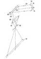
図4の実施例は、ホログラムカラーフィルター5の背面側に配置する空間光変調器として図9を用いて説明したデジタルマイクロミラーデバイス(DMD)37を用いた例であり、ホログラムカラーフィルター5で分光された赤色回折成分34R、緑色回折成分34G、青色回折成分34Bがそれぞれが集光する位置近傍にDMD37の微小ミラー38が位置するように、DMD37を配置する。このような配置をとると、図4の場合は、画素RとBの位置が変調を受けているので、反射光35R、35Bは所定の方向に反射し、これに対し画素Gは変調されていないので、反射光35Gは反射光35R、35Bと異なる方向に反射する。したがって、例えば反射光35R、35Bの方向から観察することによって、カラー画像が観察でき、明るいカラー画像表示が可能になる。
【0034】
この実施例も投影画像表示装置として用いることができる。図5にその場合の断面図を示す。照明装置14からの白色平行照明光33を画像表示装置30へ入射させるまでの構成は図2の場合と同様である。図5のDMD37を用いる構成では、投影画像を形成する表示光35の射出角が大きいので、投影レンズ18とスクリーン19は画像表示装置30に対して偏心配置する場合もある。そして、このDMD37を用いる場合、画素を構成する微小ミラー38が変調を受けない場合でも表示光35と異なる方向へ出る反射光40(図4の場合は反射光35G)が存在するので、これを除去するために、投影レンズ18の後側焦点近傍にスリット39を配置してあり、不要反射光40が投影レンズ18へ入射しても、表示光35と方向が異なるので、スリット39の開口を通過してスクリーン19に達することができない。したがって、微小ミラー38で変調を受けて反射方向が変化させられた表示光35のみがスクリーン19に達して明るいカラー表示画像を形成する。なお、反対に、表示光35をスリット39でブロックし、反射光40のみを通過させるようにして画像表示することもできる。
【0035】
以上、本発明のホログラムカラーフィルターを用いた画像表示装置をいくつかの実施例に基づいて説明してきたが、本発明はこれら実施例に限定されず種々の変形が可能である。例えば、PDLC表示素子の代わりにTN型あるいはスーパーツイストネマチック(STN)型の通常の液晶表示素子等を用いることもできる。
【0036】
【発明の効果】
以上の説明から明らかなように、本発明のホログラムカラーフィルターを用いた画像表示装置によると、ホログラムカラーフィルターと透過型空間光変調器と反射層とから画像表示装置を構成し、そのホログラムカラーフィルター側から照明するようにしたので、明るい反射型のカラー画像表示装置を実現することができる。透過型空間光変調器としは通常の液晶表示素子以外に高分子分散型液晶表示素子、DMD型表示素子等が利用でき、これらを用いるとより明るいカラー画像表示が可能になる。
【図面の簡単な説明】
【図1】本発明のホログラムカラーフィルターを用いる反射型の画像表示装置の1実施例の模式的断面図である。
【図2】図1に示した画像表示装置を用いた投影画像表示装置の断面図である。
【図3】別の実施例の画像表示装置の図1と同様な模式的断面図である。
【図4】さらに別の実施例の画像表示装置の図1と同様な模式的断面図である。
【図5】図4に示した画像表示装置を用いた投影画像表示装置の断面図である。
【図6】ホログラムカラーフィルターを用いた液晶表示装置の概略断面図である。
【図7】図6の液晶表示装置を用いた液晶投影表示装置の断面図である。
【図8】液晶表示素子の断面図である。
【図9】デジタルマイクロミラーデバイスの構成と作用を説明するための図である。
【符号の説明】
5…ホログラムアレー(ホログラムカラーフィルター)
5′…微小ホログラム
14…照明装置
15…メタルハライドランプ
16…放物面鏡
18…投影レンズ
19…スクリーン
30…画像表示装置
31…高分子分散型液晶(PDLC)表示素子
31′…画素
32…反射層
33…照明光
34R、34G、34B…回折分光成分
35…表示光
35R、35G、35B…透過光(反射光)
36…反射型ホログラム
36R、36G、36B…干渉縞
37…デジタルマイクロミラーデバイス(DMD)
38…微小ミラー
39…スリット
40…不要反射光
R、G、B…分色画素[0001]
BACKGROUND OF THE INVENTION
The present invention relates to an image display device using a hologram color filter, and in particular, a reflective image display in which a spatial light modulator such as a polymer-dispersed liquid crystal display element or a digital micromirror device type display element is combined with a hologram color filter. Relates to the device.
[0002]
[Prior art]
Conventionally, a backlight is indispensable for display in a color liquid crystal display device using an absorption color filter such as a pigment or a dye. However, just using white light as it is from behind the color liquid crystal display device, its utilization efficiency is very low. The main reasons are as follows.
[0003]
(1) The area occupied by the black matrix other than the cells of each color is large, and the light hitting it is wasted.
(2) Among white light incident on each pixel, the color components that pass through the color filters of R (red), G (green), and B (blue) are limited, so other complementary color components are wasted. End up.
(3) There is a loss due to absorption by the color filter.
[0004]
In order to solve such problems, for example, a microlens array is installed in front of the color filter, and the backlight of the white light is condensed on the color filter cells R, G, and B, respectively. Methods for increasing the utilization efficiency have been conventionally known.
[0005]
However, even with this method, since the
[0006]
Furthermore, Japanese Patent Laid-Open No. 4-60538 proposes a liquid crystal projector that improves the light utilization efficiency by using three dichroic mirrors and a microlens array without using such a color filter. In this case, the absorption color filter using the above-mentioned pigments, dyes and the like is not necessary, and the above problems (1) to (3) are solved and the brightness of the color image is improved, but three dichroic mirrors are used. Since this is necessary, the optical system / device becomes large and bulky. In addition, there is a problem that the cost becomes high.
[0007]
In view of such circumstances, the present applicant used a color filter using a hologram and the same in Japanese Patent Application No. 5-12170 in order to greatly improve the utilization efficiency of a backlight for liquid crystal display and the like. A liquid crystal display device was proposed.
[0008]
Further, a liquid crystal projection display device that displays a bright color image on a screen by changing the liquid crystal display device using such a hologram color filter to a projection type has been proposed in Japanese Patent Application No. 5-242292.
[0009]
Hereinafter, a liquid crystal display device and a liquid crystal projection display device using such a hologram color filter will be briefly described.
First, a liquid crystal display device using a hologram color filter will be described with reference to a sectional view of FIG. In the figure, a
[0010]
The
[0011]
Because of such a configuration, when the
[0012]
As described above, by using the
[0013]
Further, the liquid crystal display device using the hologram color filter having the configuration as shown in FIG. 6 is used as it is as a direct-view type liquid crystal display device or as a spatial light modulation element for projection display. Can be used as FIG. 7 is a cross-sectional view in that case. The first polarizing
[0014]
In the liquid crystal display device using the hologram color filter as described above, the liquid
[0015]
By controlling the voltage applied between the transparent pixel electrode 24 and the
[0016]
On the other hand, a polymer dispersed liquid crystal (PDCL) display element has been proposed as a liquid crystal display element. This is to display by controlling the white turbid state and the transparent state by turning on and off the voltage, and since a polarizing plate is not used unlike conventional liquid crystal display elements such as twisted nematic (TN) liquid crystal, a bright display is achieved. (See “Flat Panel Display” '91, pp. 214-224). Such a liquid crystal is composed of a polymer / liquid crystal composite film, and there are a liquid crystal phase separated into droplets in the polymer and a liquid crystal continuous phase. .
[0017]
Also, a digital micromirror device (DMD) has been proposed as a display element capable of two-dimensional display by deforming a minute mirror. As shown in the perspective view of FIG. 9A, a minute mirror M corresponding to each pixel is two-dimensionally arranged, and a mirror M ′ at a predetermined address is tilted about a diagonal line as a mirror. A two-dimensional pattern is displayed by reflecting light incident on M ′ from a certain direction in a different direction from the non-tilt mirror (“IEEE Spectrum Vol.30, No.11, pp”). 9 (b) shows the support driving structure of each mirror M. Each of the mirrors M is a pair of support posts P standing on the silicon substrate S at one diagonal corner. By applying a voltage to one of the pair of electrodes E provided on the substrate S on the back side of the mirror M, the diagonal line between the hinges T is axially rotated by an electrostatic force. Thus, the surface of the mirror M is rotated.
[0018]
[Problems to be solved by the invention]
As described above, the image display device using the above-described hologram color filter according to the proposal of the present applicant is based on the assumption that a normal liquid crystal display element such as a TN liquid crystal is used, and the backlight is incident from the back side. It was configured as a transmission type. However, no image display device has been proposed in which a hologram type color filter is combined with a reflective type in which illumination light is incident from the surface side of a spatial light modulator such as a polymer dispersion type liquid crystal display element or DMD type display element.
[0019]
The present invention has been made in view of such a situation, and an object of the present invention is to make illumination light incident from the surface side using a hologram color filter according to the applicant's proposal and to disperse a polymer as a spatial light modulator. It is an object to provide a bright reflective color image display device that can use a liquid crystal display device and a DMD display device.
[0020]
[Means for Solving the Problems]
An image display device using the hologram color filter of the present invention that achieves the above object comprises an illumination light source and an array of element condensing holograms, each of the element condensing holograms being normal to the hologram recording surface. A hologram color filter for dispersing the wavelength of white light incident at a predetermined angle in a direction substantially along the hologram recording surface, a reflection layer disposed in the vicinity of the light collection surface, the hologram color filter, A transmissive spatial light modulator disposed between the reflective layers, and the reflected light modulated by the transmissive spatial light modulator and reflected by the reflective layer is at an angle with respect to the normal of the reflective layer It is characterized by comprising.
[0021]
In this case, it is desirable that the reflected light modulated by the transmissive spatial light modulator and reflected by the reflective layer is configured to form an angle with respect to the normal line of the reflective layer.
Further, as the transmissive spatial light modulator, a polymer dispersion type liquid crystal display element that controls a white turbid state and a transparent state by applying and releasing a voltage can be used. In addition, a reflection hologram in which interference fringes are distributed and recorded so as to reflect the dispersed color components can also be used as the reflection layer.
[0023]
Note that this image display apparatus can also project the reflected light in an enlarged manner by the projection optical system.
[0024]
In the present invention, an image display device is composed of a hologram color filter, a transmissive spatial light modulator, and a reflective layer, and illumination is performed from the hologram color filter side, thereby realizing a bright reflective color image display device. can do. As the transmissive spatial light modulator, in addition to a normal liquid crystal display element, a polymer dispersion type liquid crystal display element, a DMD type display element, or the like can be used, and by using these, a brighter color image display becomes possible.
[0025]
DETAILED DESCRIPTION OF THE INVENTION
Examples of image display devices using the hologram color filter of the present invention will be described below.
FIG. 1 is a schematic cross-sectional view of one embodiment of a reflection type image display apparatus using a hologram color filter as shown in FIG. In this embodiment, a polymer dispersed liquid crystal (PDLC)
[0026]
Also in this case, the
[0027]
With this arrangement, when the
[0028]
Here, as described above, the
[0029]
Further, an image display device using the
[0030]
In the case of FIG. 1, since the simple
[0031]
Therefore, in the embodiment of FIG. 3, a
[0032]
Therefore, in the case of this embodiment, the directions of the
[0033]
The embodiment of FIG. 4 is an example in which the digital micromirror device (DMD) 37 described with reference to FIG. 9 is used as a spatial light modulator disposed on the back side of the
[0034]
This embodiment can also be used as a projection image display device. FIG. 5 shows a cross-sectional view in that case. The configuration until the white parallel illumination light 33 from the
[0035]
As described above, the image display apparatus using the hologram color filter of the present invention has been described based on several embodiments. However, the present invention is not limited to these embodiments, and various modifications can be made. For example, a normal liquid crystal display element of a TN type or a super twist nematic (STN) type can be used instead of the PDLC display element.
[0036]
【The invention's effect】
As is apparent from the above description, according to the image display device using the hologram color filter of the present invention, the image display device is constituted by the hologram color filter, the transmissive spatial light modulator, and the reflective layer, and the hologram color filter Since the illumination is performed from the side, a bright reflective color image display device can be realized. As the transmissive spatial light modulator, in addition to a normal liquid crystal display element, a polymer dispersion type liquid crystal display element, a DMD type display element, or the like can be used, and by using these, a brighter color image display becomes possible.
[Brief description of the drawings]
FIG. 1 is a schematic cross-sectional view of one embodiment of a reflection type image display apparatus using a hologram color filter of the present invention.
FIG. 2 is a cross-sectional view of a projection image display device using the image display device shown in FIG.
FIG. 3 is a schematic cross-sectional view similar to FIG. 1 of an image display apparatus according to another embodiment.
FIG. 4 is a schematic cross-sectional view similar to FIG. 1 of an image display apparatus of still another embodiment.
5 is a cross-sectional view of a projection image display apparatus using the image display apparatus shown in FIG.
FIG. 6 is a schematic cross-sectional view of a liquid crystal display device using a hologram color filter.
7 is a cross-sectional view of a liquid crystal projection display device using the liquid crystal display device of FIG.
FIG. 8 is a cross-sectional view of a liquid crystal display element.
FIG. 9 is a diagram for explaining the configuration and operation of a digital micromirror device.
[Explanation of symbols]
5. Hologram array (hologram color filter)
5 '...
36:
38 ...
Claims (4)
Translated fromJapanesePriority Applications (1)
| Application Number | Priority Date | Filing Date | Title |
|---|---|---|---|
| JP9528996AJP3869488B2 (en) | 1996-04-17 | 1996-04-17 | Image display device using hologram color filter |
Applications Claiming Priority (1)
| Application Number | Priority Date | Filing Date | Title |
|---|---|---|---|
| JP9528996AJP3869488B2 (en) | 1996-04-17 | 1996-04-17 | Image display device using hologram color filter |
Publications (2)
| Publication Number | Publication Date |
|---|---|
| JPH09281917A JPH09281917A (en) | 1997-10-31 |
| JP3869488B2true JP3869488B2 (en) | 2007-01-17 |
Family
ID=14133624
Family Applications (1)
| Application Number | Title | Priority Date | Filing Date |
|---|---|---|---|
| JP9528996AExpired - Fee RelatedJP3869488B2 (en) | 1996-04-17 | 1996-04-17 | Image display device using hologram color filter |
Country Status (1)
| Country | Link |
|---|---|
| JP (1) | JP3869488B2 (en) |
Families Citing this family (27)
| Publication number | Priority date | Publication date | Assignee | Title |
|---|---|---|---|---|
| US6674562B1 (en) | 1994-05-05 | 2004-01-06 | Iridigm Display Corporation | Interferometric modulation of radiation |
| US8928967B2 (en) | 1998-04-08 | 2015-01-06 | Qualcomm Mems Technologies, Inc. | Method and device for modulating light |
| WO1999052006A2 (en) | 1998-04-08 | 1999-10-14 | Etalon, Inc. | Interferometric modulation of radiation |
| WO2003007049A1 (en) | 1999-10-05 | 2003-01-23 | Iridigm Display Corporation | Photonic mems and structures |
| JP2001305517A (en)* | 2000-04-18 | 2001-10-31 | Dainippon Printing Co Ltd | Reflection type image display device using hologram color filter |
| JP2001311813A (en)* | 2000-04-28 | 2001-11-09 | Dainippon Printing Co Ltd | Image display device using hologram color filter |
| JP2001356337A (en)* | 2000-06-15 | 2001-12-26 | Kyocera Corp | Transflective liquid crystal display |
| GB0121308D0 (en) | 2001-09-03 | 2001-10-24 | Thomas Swan & Company Ltd | Optical processing |
| JP3780885B2 (en) | 2001-09-04 | 2006-05-31 | セイコーエプソン株式会社 | Reflective display device and electronic apparatus |
| CN100363847C (en)* | 2001-12-29 | 2008-01-23 | 青岛海洋大学 | Method for generating synthetic hologram by digital microreflector |
| TWI289708B (en) | 2002-12-25 | 2007-11-11 | Qualcomm Mems Technologies Inc | Optical interference type color display |
| US7342705B2 (en) | 2004-02-03 | 2008-03-11 | Idc, Llc | Spatial light modulator with integrated optical compensation structure |
| US7355780B2 (en) | 2004-09-27 | 2008-04-08 | Idc, Llc | System and method of illuminating interferometric modulators using backlighting |
| US7710632B2 (en) | 2004-09-27 | 2010-05-04 | Qualcomm Mems Technologies, Inc. | Display device having an array of spatial light modulators with integrated color filters |
| US7525730B2 (en) | 2004-09-27 | 2009-04-28 | Idc, Llc | Method and device for generating white in an interferometric modulator display |
| US7630123B2 (en) | 2004-09-27 | 2009-12-08 | Qualcomm Mems Technologies, Inc. | Method and device for compensating for color shift as a function of angle of view |
| US7916980B2 (en) | 2006-01-13 | 2011-03-29 | Qualcomm Mems Technologies, Inc. | Interconnect structure for MEMS device |
| EP1943555B1 (en) | 2006-10-06 | 2012-05-02 | QUALCOMM MEMS Technologies, Inc. | Optical loss structure integrated in an illumination apparatus of a display |
| EP1943551A2 (en) | 2006-10-06 | 2008-07-16 | Qualcomm Mems Technologies, Inc. | Light guide |
| US8721149B2 (en) | 2008-01-30 | 2014-05-13 | Qualcomm Mems Technologies, Inc. | Illumination device having a tapered light guide |
| WO2010085286A1 (en) | 2009-01-23 | 2010-07-29 | Qualcomm Mems Technologies, Inc. | Integrated light emitting and light detecting device |
| CN102449512A (en) | 2009-05-29 | 2012-05-09 | 高通Mems科技公司 | Illumination devices and methods of fabrication thereof |
| US8848294B2 (en) | 2010-05-20 | 2014-09-30 | Qualcomm Mems Technologies, Inc. | Method and structure capable of changing color saturation |
| GB2504970A (en) | 2012-08-15 | 2014-02-19 | Swan Thomas & Co Ltd | Optical device and methods to reduce cross-talk |
| US9183812B2 (en) | 2013-01-29 | 2015-11-10 | Pixtronix, Inc. | Ambient light aware display apparatus |
| FR3010831B1 (en)* | 2013-07-29 | 2019-06-28 | Sunpartner Technologies | RETROTECTIVE DISPLAY DEVICE WITH INTEGRATED PHOTOVOLTAIC CELLS |
| CN108459455A (en)* | 2016-02-29 | 2018-08-28 | 青岛海信电器股份有限公司 | A kind of projection display system |
- 1996
- 1996-04-17JPJP9528996Apatent/JP3869488B2/ennot_activeExpired - Fee Related
Also Published As
| Publication number | Publication date |
|---|---|
| JPH09281917A (en) | 1997-10-31 |
Similar Documents
| Publication | Publication Date | Title |
|---|---|---|
| JP3869488B2 (en) | Image display device using hologram color filter | |
| JP3418508B2 (en) | Projection type image display device | |
| US6910777B2 (en) | Projector | |
| EP0658794B1 (en) | Liquid crystal projection device and liquid crystal display device | |
| JP3047311B2 (en) | Liquid crystal display | |
| JP3608756B2 (en) | Liquid crystal display | |
| JP3649360B2 (en) | Hologram color filter system | |
| JP3528992B2 (en) | Liquid crystal display using hologram color filter | |
| JP3717016B2 (en) | Reflective liquid crystal display device using hologram | |
| JP3958807B2 (en) | Reflective direct-view color display device using hologram color filter | |
| JP4293327B2 (en) | Hologram color filter and image display device using the same | |
| JPH05323307A (en) | Direct view type display and projection type display | |
| JP3568064B2 (en) | Liquid crystal display using hologram color filter | |
| JP3575647B2 (en) | Liquid crystal display using hologram color filter | |
| JP3608757B2 (en) | Liquid crystal display device using hologram color filter | |
| JP2000275441A (en) | Hologram color filter and color image display device using the same | |
| JPH09292606A (en) | Projection type liquid crystal display | |
| JP3613422B2 (en) | Color display device using diffraction grating | |
| JP4255042B2 (en) | Color liquid crystal display system using hologram color filter | |
| JP4458390B2 (en) | Reflective image display device using hologram color filter | |
| JP3514341B2 (en) | Liquid crystal display using hologram color filter | |
| JP4600953B2 (en) | Reflective hologram color filter and reflective liquid crystal display device using the same | |
| JP2001166148A (en) | Image display device | |
| JP3916244B2 (en) | Reflective liquid crystal display device using hologram | |
| JPH103077A (en) | Color filter system and liquid crystal display device using the same |
Legal Events
| Date | Code | Title | Description |
|---|---|---|---|
| A521 | Written amendment | Free format text:JAPANESE INTERMEDIATE CODE: A523 Effective date:20060919 | |
| A61 | First payment of annual fees (during grant procedure) | Free format text:JAPANESE INTERMEDIATE CODE: A61 Effective date:20061013 | |
| R150 | Certificate of patent or registration of utility model | Free format text:JAPANESE INTERMEDIATE CODE: R150 | |
| FPAY | Renewal fee payment (event date is renewal date of database) | Free format text:PAYMENT UNTIL: 20091020 Year of fee payment:3 | |
| FPAY | Renewal fee payment (event date is renewal date of database) | Free format text:PAYMENT UNTIL: 20101020 Year of fee payment:4 | |
| FPAY | Renewal fee payment (event date is renewal date of database) | Free format text:PAYMENT UNTIL: 20111020 Year of fee payment:5 | |
| FPAY | Renewal fee payment (event date is renewal date of database) | Free format text:PAYMENT UNTIL: 20121020 Year of fee payment:6 | |
| FPAY | Renewal fee payment (event date is renewal date of database) | Free format text:PAYMENT UNTIL: 20131020 Year of fee payment:7 | |
| LAPS | Cancellation because of no payment of annual fees |