JP3869029B2 - Stereoscopic endoscope system - Google Patents
Stereoscopic endoscope systemDownload PDFInfo
- Publication number
- JP3869029B2 JP3869029B2JP11752395AJP11752395AJP3869029B2JP 3869029 B2JP3869029 B2JP 3869029B2JP 11752395 AJP11752395 AJP 11752395AJP 11752395 AJP11752395 AJP 11752395AJP 3869029 B2JP3869029 B2JP 3869029B2
- Authority
- JP
- Japan
- Prior art keywords
- stereoscopic
- stereoscopic endoscope
- endoscope
- hmd
- image
- Prior art date
- Legal status (The legal status is an assumption and is not a legal conclusion. Google has not performed a legal analysis and makes no representation as to the accuracy of the status listed.)
- Expired - Fee Related
Links
- 230000003287optical effectEffects0.000claimsdescription29
- 238000003780insertionMethods0.000claimsdescription27
- 230000037431insertionEffects0.000claimsdescription27
- 210000001508eyeAnatomy0.000claimsdescription18
- 210000001747pupilAnatomy0.000claimsdescription11
- 238000012545processingMethods0.000description17
- 238000010586diagramMethods0.000description11
- 239000004973liquid crystal related substanceSubstances0.000description10
- 210000003128headAnatomy0.000description7
- 238000002674endoscopic surgeryMethods0.000description6
- 208000013057hereditary mucoepithelial dysplasiaDiseases0.000description6
- 230000000694effectsEffects0.000description4
- 238000003384imaging methodMethods0.000description4
- 238000000034methodMethods0.000description4
- 230000000007visual effectEffects0.000description4
- 238000005452bendingMethods0.000description3
- 238000001444catalytic combustion detectionMethods0.000description3
- 210000000683abdominal cavityAnatomy0.000description2
- 210000004556brainAnatomy0.000description2
- 238000013461designMethods0.000description2
- 230000003187abdominal effectEffects0.000description1
- 210000005252bulbus oculiAnatomy0.000description1
- 238000007796conventional methodMethods0.000description1
- 201000010099diseaseDiseases0.000description1
- 208000037265diseases, disorders, signs and symptomsDiseases0.000description1
- 230000006870functionEffects0.000description1
- 238000009434installationMethods0.000description1
- 238000002350laparotomyMethods0.000description1
- 230000002093peripheral effectEffects0.000description1
- 230000035807sensationEffects0.000description1
- 238000004904shorteningMethods0.000description1
- 238000001356surgical procedureMethods0.000description1
- 210000000115thoracic cavityAnatomy0.000description1
Images


Landscapes
- Instruments For Viewing The Inside Of Hollow Bodies (AREA)
- Endoscopes (AREA)
- Testing, Inspecting, Measuring Of Stereoscopic Televisions And Televisions (AREA)
Description
Translated fromJapanese【0001】
【産業上の利用分野】
本発明は、細長い挿入部を有し視差を有する左右の像を撮像する立体視内視鏡と、立体視内視鏡で取得した左右の画像を観察者の左右の眼に伝達する頭部装着型立体表示装置を有する立体視内視鏡システムに関する。
【0002】
【従来の技術】
近年、医療の外科分野において、内視鏡と専用処置具を用いた低侵襲手技が普及しつつある。従来なら開腹手術を必要とした疾病を内視鏡下で低侵襲に処置することが可能となることで、入院期間の短縮等により患者の社会的負担が軽減される。そのため、低侵襲手技である内視鏡下外科手術は、今後も発展が期待されている。
【0003】
この内視鏡下外科手術では、内視鏡で取得した体腔内の画像をTVモニタ等で観察しながら処置具の遠隔操作をして処置を行う。
【0004】
この際の問題点として、処置具の誘導の困難さが挙げられる。特に、奥行き方向の情報は、従来の内視鏡では得られないため、奥行き方向の処置具誘導は試行錯誤で行わざるを得ず、処置に時間がかかる等の問題を生じていた。このため、奥行き方向の情報を観察者に提供できる立体視内視鏡システムが開発されている。
【0005】
立体視内視鏡システムの観察系は通常2眼式であり、図6に示すように、細長い挿入部を備え視差を有する観察部位の左右の像を撮像するための観察光学系と撮像素子を内蔵した立体視内視鏡101と、この立体視内視鏡101からの左右の像の映像信号により立体像を生成する立体映像信号処理装置102と、立体映像信号処理装置102の立体像を表示する立体表示装置103とからなる。
【0006】
そして、この立体視内視鏡システムでは、立体視内視鏡101の観察光学系により物体の像が撮像素子の撮像面に形成される。視差を有する左右の像を得るために、観察光学系には様々の方式が用いられる。撮像素子で取得した左右の画像は、映像信号として立体視内視鏡101から立体映像信号処理装置102に伝達される。立体映像信号処理装置102は後段の立体表示装置103に対応して必要な信号処理を行う。立体表示装置103は、立体映像信号処理装置102から送出された立体像を基に表示素子上に左右の画像を形成する。
【0007】
左右の画像を分離して観察者の両眼に伝達するために、立体表示装置103にも様々の方式が存在する。
【0008】
2眼式の立体表示装置103は、大きく二つの方式に分けられ、一つは据置型TVモニタを用いるものであり、もう一つはHMD(ヘッド・マウンティング・デバイス)と呼ばれる頭部装着型のものである。据置型TVモニタに対するHMDの利点として、視野の大きさ(眼に映る画像の大きさ)が使用時に固定されること、及び視野の大きさを設計上任意に選べることが挙げられる。据置型TVモニタでは、視野の大きさは観察距離に依存するため固定されない。しかし、据置型TVモニタにおいて視野を大きくするにはTVモニタの画面を巨大化せねばならず装置の設置上の問題を生じる。このため、ある程度以上の視野の大きさを得ることは実用上困難である。
【0009】
これに対し、HMDでは、液晶等の表示素子サイズと,接眼光学系の選択により据置型TVモニタでは得られない大きな視野を得ることができる。
【0010】
そこで、立体視による内視鏡下外科手術においては、現状は据置型TVモニタを用いた立体表示装置が主流であるが、今後はHMDも普及していくと考えられる。特に、先に述べたHMDの利点である視野の大きさの固定と選択自由度の高さは、立体視における自然な臨場感の達成のためには重要な要因となる。
【0011】
例えば立体視内視鏡と頭部装着型立体表示装置の組み合わせに関する従来技術としては、USP4651201に頭部装着型立体表示装置を含む立体視内視鏡システムが開示されている。
【0012】
【発明が解決しようとする課題】
しかしながら、自然な臨場感は立体表示装置103のみで定まるものではなく、立体画像入力装置となる立体視内視鏡101との関係によって定まるが、上記従来例ではそれらの好ましい関係については十分に検討がなされておらず、結果として自然な臨場感を得ることができないといった問題がある。
【0013】
本発明は、上記事情に鑑みてなされたものであり、立体視内視鏡と頭部装着型立体表装置の好ましい関係を設定することにより、要求される自然な臨場感を得ることのできる立体視内視鏡システムを提供することを目的としている。
【0014】
【課題を解決するための手段】
本発明の立体視内視鏡システムは、細長い挿入部を有し視差を有する左右の像を撮像する立体視内視鏡と、前記立体視内視鏡で取得した左右の画像を観察者の左右の眼に伝達する頭部装着型立体表示装置を有する立体視内視鏡システムにおいて、条件(1)0.4<β/α<2、但し、αは前記立体視内視鏡の画角、βは前記頭部装着型立体表示装置の視角、条件(2): 0.043<E/D<0.52、但し、Eは前記立体視内視鏡の挿入部先端における左右の光学系の入射瞳間隔、Dは前記立体視内視鏡の挿入部外径、を満足することを特徴とする。
【0015】
【実施例】
以下、図面を参照しながら本発明の実施例について述べる。
【0016】
図1ないし図5は本発明の一実施例に係わり、図1は立体視内視鏡システムの構成を示す構成図、図2は図1のHMDの構成を示す構成図、図3は図1の立体視内視鏡システムの作用を説明する概念図、図4は図1のHMDの視角βと立体視内視鏡の画角αの定義を説明する第1の説明図、図5は図1のHMDの視角βと立体視内視鏡の画角αの定義を説明する第2の説明図である。
【0017】
本実施例の立体視内視鏡システムは、図1に示すように、観察部位の視差を有する左右の映像信号を得る立体視硬性鏡1と、立体視硬性鏡1により得られた観察部位の右映像信号を信号処理する右映像信号処理装置2と、立体視硬性鏡1により得られた観察部位の左映像信号を信号処理する左映像信号処理装置3と、観察者の頭部に装着され観察部位の立体像を表示するHMD4と、右映像信号処理装置2及び左映像信号処理装置3で信号処理された左右の映像信号によりHMD4に立体像を表示させるHMDコントローラ5とを備えて構成される。
【0018】
立体視硬性鏡1は、体腔内に挿入する硬性な挿入部を有するスコープ部11と、スコープ部11に接続して用いられ観察部位の視差を有する左右の像を撮像するカメラヘッド部12とから構成される。スコープ部11は、対物光学系15とリレー光学系16が軸対称な1本の光学系により構成されている。対物光学系15で結像した像はリレー光学系16によって所定の距離だけ伝送され、リレー光学系16の後端にはカメラヘッド12の対物光学系17により瞳を空間的に2つに分割することにより視差のある左右一対の像を撮像手段としてのCCD18、19によって撮像される。撮像された左右一対の像は電気信号に変換され、右映像信号処理装置2及び左映像信号処理装置3で信号処理されNTSC等の汎用映像信号に変換された後、HMDコントローラ5による制御により、HMD4に立体像が表示される。なお、HMDコントローラ5はHMD4の各種制御と電源の供給を行う。
【0019】
図2に示すように、HMD4は、観察者の例えば右眼21の視線から外れた位置に配置され観察部位の右画像を表示する液晶ディスプレイ(LCD)22と、このLCD22に表示された右画像を右眼21に伝送する光学系23とを備え、光学系23はハーフミラー面24を挟んで2つのプリズム25、26を接合して構成されており、下側のプリズム26の凹面鏡28は拡大レンズの機能を有している。そして、LCD22に表示された右画像は透過し凹面鏡28により拡大反射され、ハーフミラー面24で直角に反射され右眼21に供給されるようになっている。光学系23の右眼21に対向した位置には液晶シャッタ29が配置されていて、図1に示すように、HMD4のハウジングのこの液晶シャッタ29に対応する部分は透明部30になっている。そして、液晶シャッタ29を閉じる(不透過)と暗い中にLCD22に表示された画像が拡大されて観察され、液晶シャッタ29を開く(透過)と外が見えるように構成されている。なお、左眼側も同様に構成されている。
【0020】
本実施例の立体視内視鏡システムでは、図1に示すように、立体視硬性鏡1に替えて立体視軟性鏡31も接続可能である。立体視軟性鏡31は、体腔内に挿入する細長い挿入部32を備え、この挿入部32の先端側は湾曲可能な湾曲部33になっており、挿入部32の基端に設けられた操作部34の図示しない湾曲操作ノブを操作することにより湾曲部33を湾曲させることができるようになっている。挿入部32の先端内部には、左右2つに分割された光学系35が内蔵されており、左右の光学系35はそれぞれ対物レンズ系36と固体撮像素子例えばCCD37からなり、左右のCCD37からの映像信号はそれぞれの左映像信号処理装置3及び右映像信号処理装置2に伝送され、以後は立体視硬性鏡の場合と同様の処理が行なわれるようになっている。
【0021】
上記HMD4及び立体視硬性鏡1または立体視軟性鏡31である立体視内視鏡の仕様例は以下の通りである。
【0022】
<HMD>
HMD−Aタイプ:視角β=36゜ 液晶画素数=18万画素
HMD一Bタイプ:視角β=50゜ 液晶画素数=38万画素
HMD−Cタイプ:視角β=70゜ 液晶画素数=60万画素
<立体視内視鏡>
適用部位 腹腔 腹腔 脳 関節 胸腔
挿入部タイプ 硬性 硬性 硬性 硬性 軟性
画角α[゜] 65 70 50 90 70
挿入部外径D[mm] 12 10 4 4 10
入射瞳間隔E[mm] 1.7 4 0.18 0.25 5
E/D 0.142 0.4 0.045 0.063 0.5
β/α[HMD-Aタイプ] 0.55 0.51 0.72 0.4 0.51
β/α[HMD-Bタイプ] 0.77 0.71 1 0.56 0.71
β/α[HMD-Cタイプ] 1.08 1 1.4 0.78 1
このように構成された本実施例の作用について説明する。
【0023】
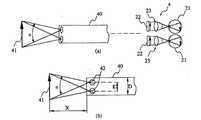
図3は本実施例の作用を説明するための概念図であり、図3(a)に示すように、内視鏡下外科手術において自然な臨場感を得るために、立体視硬性鏡1または立体視軟性鏡31である立体視内視鏡40による物体41の像は、人間の頭部に装着されるHMD4の光学系23により眼21で観察状態を再現することが望まれる。このため、図3(b)の如くあたかも人間の眼球を仮想眼球42として立体視内視鏡40の挿入部先端に備えられているような状態を作り出すことが望ましい。
【0024】
この際に最も重要となるのが立体視内視鏡40の画角αとHMDの視角βの関係である。本実施例の構成では、立体視内視鏡の画角αとHMDの視角βを略一致させることにより自然な臨場感が得られるようにしている。β/α=1であれば、物体から立体視内視鏡40に入射する光束の角度とHMDから眼21に入射する光束の角度が等しくなり、最も自然な臨場感が得られる。1でなくとも(1)式の範囲であれば大きな違和感を生じない。
【0025】
0.4<β/α<2 (1)
β/αが0.4以下になると、視角βが狭くなり、眼21に映る物体41の像が望ましい大きさより小さくなって十分な臨場感が得られない。この場合、観察者は画像に対しもの足りなさを感じるため望ましくない。
【0026】
また、β/αが2以上になると、視角βが広くなり眼に映る物体の像が望ましい大きさより大きくなって過剰な臨場感が生じる。この場合、内視鏡下外科手術のような長時間の使用時には観察者の疲労を過度に増大させるため望ましくない。このため、(1)式を満足させている。
【0027】
次に(1)式に用いるHMD4の視角βと立体視内視鏡40の画角αの定義について述べる。HMD4の視角β、及び立体視内視鏡40の画角αはHMD4のLCD22に表示される内視鏡画像の最周辺部に相当する値を用いる。図4はHMD4における視角βの定義を示す図である。図4は内視鏡接続時の画像がHMD4のLCD22の画面全体に表される場合であり、HMD4の視角βはLCD22画面の対角に相当する値を用い、立体視内視鏡40の画角αもHMD4のLCD22画面の対角に相当する値を用いる。図5は内視鏡接続時の画像が画面の一部に表示される場合であり、HMD4の視角βは対角ではなく内視鏡画像の最大長に相当する値を用い、立体視内視鏡40の画角αも画像の最大長に相当する値を用いる。
【0028】
なお、先に述べた条件に加え、下記の(2)式の条件を満足することが望ましい。
【0029】
0.043<E/D<0.52 (2)
但し、Eは立体視内視鏡40の挿入部先端における左右の光学系の入射瞳間隔、Dは立体視内視鏡40の挿入部外径である。
【0030】
この(2)式について説明する。(2)式は自然な立体感を得るための条件である。図3(b)の状態を想定した場合、人間の眼幅に相当する入射瞳間隔Eと物体距離Xの間には望ましい関係が存在する。実際の人間の観察においては眼幅は約65mmであり、立体視を行いやすい観察距離はおよそ0.25mから3mである。人間の眼幅と観察距離の比率を立体視内視鏡の挿入部先端で再現するには以下の(3)式を満足させる必要がある。
【0031】
65/3000<E/X<65/250 (3)
なお、物体距離Xは、内視鏡下外科手術の場合、処置を行う距離を想定するのが望ましい。内視鏡下外科手術は人体の各部位を対象に広まっているが、一般的に腹腔のように広い空間を確保できる部位には挿入部外径Dの太い内視鏡が用いられ、関節や脳のように狭い空間しか得られない部位には細い内視鏡が用いられる。このため、挿入部外径Dと物体距離Xがおおよそ比例すると仮定すると、経験的に以下の(4)式の関係が設定できる。
【0032】
X=2D (4)
以上の(3)、(4)式より物体距離Xを消去することで(2)式が導かれる。つまり、(2)式のE/Dは立体視内視鏡40の構成のみで定まる。なお、E/Dが0.043を下回ると立体感が小さくなりすぎ、0.52を上回ると立体感が大きくなりすぎ、共に好ましくない。
【0033】
なお、立体表示装置をHMD4に限定した理由は、先に述べたように視野の大きさ(視角)の固定と選択自由度の高さにあるが、据置型においてもHMD4と同様の観察条件が得られるのであれば望ましいことには変わりない。
【0034】
以上、立体視内視鏡40とHMD4との関係について述べてきたが、先に示した(2)式の条件については、立体視内視鏡40単独で定まるものであり、立体表示装置の形態にかかわらず満足するのが望ましい。このため、細長い挿入部を有し視差を有する左右の像を撮像する立体視内視鏡40は(2)式を満足するように構成するのが望ましい。
【0035】
また、立体視硬性鏡1のスコープ部は光学系が1本の光軸のみを有する瞳分割式を用いるのが望ましい。独立した光軸を有する2本の光学系からなるものも知られているが、入射瞳間隔Eが2本の光学系の間隔となり(2)式におけるE/Dの値が瞳分割式に比べ大きくなる。このため、E/Dの値を上限の0.52以下にすることが機械設計上の大きな制約となり好ましくない。
【0036】
以上のように本実施例では、立体視内視鏡40の画角αとHMDの視角βを略一致、または0.4<β/α<2を満足させているので、自然な臨場感を得ることができる。
【0037】
[付記]
(付記項1) 細長い挿入部を有し視差を有する左右の像を撮像する立体視内視鏡と、前記立体視内視鏡で取得した左右の画像を観察者の左右の眼に伝達する頭部装着型立体表示装置を有する立体視内視鏡システムにおいて、
次の条件(1)を満足することを特徴とする立体視内視鏡システム。
【0038】
条件(1): 0.4<β/α<2
但し、αは前記立体視内視鏡の画角、βは前記頭部装着型立体表示装置の視角である。
【0039】
(付記項2) 次の条件(2)を満足することを特徴とする付記項1に記載の立体視内視鏡システム。
【0040】
条件(2): 0.043<E/D<0.52
但し、Eは前記立体視内視鏡の挿入部先端における左右の光学系の入射瞳間隔、Dは前記立体視内視鏡の挿入部外径である。
【0041】
(付記項3) 細長い挿入部を有し視差を有する左右の像を撮像する立体視内視鏡において、
次の条件(2)を満足することを特徴とする立体視内視鏡。
【0042】
条件(2): 0.043<E/D<0.52
但し、Eは前記立体視内視鏡の挿入部先端における左右の光学系の入射瞳間隔、Dは前記立体視内視鏡の挿入部外径である。
【0043】
【発明の効果】
以上説明したように本発明によれば、立体視内視鏡と頭部装着型立体表装置の好ましい関係を設定でき、要求される自然な臨場感を得ることができるという効果がある。
【図面の簡単な説明】
【図1】本発明の一実施例に係る立体視内視鏡システムの構成を示す構成図
【図2】図1のHMDの構成を示す構成図
【図3】図1の立体視内視鏡システムの作用を説明する概念図
【図4】図1のHMDの視角βと立体視内視鏡の画角αの定義を説明する第1の説明図
【図5】図1のHMDの視角βと立体視内視鏡の画角αの定義を説明する第2の説明図
【図6】従来の立体視内視鏡システムの構成を示す構成図
【符号の説明】
1…立体視硬性鏡
2…右映像信号処理装置
3…左映像信号処理装置
4…HMD
5…HMDコントローラ
11…スコープ部
12…カメラヘッド部
15、17…対物光学系
16…リレー光学系
18、19…CCD
21…右眼
22…LCD
23…光学系
24…ハーフミラー面
25、26…プリズム
28…凹面鏡
29…液晶シャッタ
30…透明部
31…立体視軟性鏡[0001]
[Industrial application fields]
The present invention includes a stereoscopic endoscope that captures right and left images having a long and narrow insertion portion and parallax, and a head-mounted device that transmits left and right images acquired by the stereoscopic endoscope to the left and right eyes of an observer The present invention relates to a stereoscopic endoscope system having a stereoscopic display device.
[0002]
[Prior art]
In recent years, minimally invasive techniques using endoscopes and dedicated treatment tools are becoming popular in the field of medical surgery. Conventionally, a disease requiring an laparotomy can be treated minimally invasively under an endoscope, so that the social burden on the patient is reduced by shortening the hospitalization period. Therefore, endoscopic surgery, which is a minimally invasive technique, is expected to develop in the future.
[0003]
In this endoscopic surgical operation, treatment is performed by remotely operating the treatment tool while observing an image in the body cavity obtained by the endoscope with a TV monitor or the like.
[0004]
As a problem at this time, it is difficult to guide the treatment tool. In particular, since information in the depth direction cannot be obtained with a conventional endoscope, the treatment tool guidance in the depth direction has to be performed by trial and error, and there has been a problem that it takes time for the treatment. For this reason, stereoscopic endoscope systems that can provide information in the depth direction to an observer have been developed.
[0005]
The observation system of the stereoscopic endoscope system is usually a twin-lens system, and as shown in FIG. 6, an observation optical system and an image sensor for capturing left and right images of an observation site having a long and thin insertion portion and having parallax are provided. A built-in
[0006]
In this stereoscopic endoscope system, an image of an object is formed on the imaging surface of the imaging element by the observation optical system of the
[0007]
There are various methods for the
[0008]
The binocular
[0009]
On the other hand, in the HMD, a large field of view that cannot be obtained by a stationary TV monitor can be obtained by selecting adisplay element size such as a liquid crystal and an eyepiece optical system.
[0010]
Thus, in endoscopic surgery using stereoscopic vision, currently, stereoscopic display devices using stationary TV monitors are the mainstream, but in the future, HMDs are also expected to become widespread. In particular, fixing the size of the visual field and the high degree of freedom of selection, which are the advantages of the HMD described above, are important factors for achieving a natural presence in stereoscopic vision.
[0011]
For example, US Pat. No. 4,651,201 discloses a stereoscopic endoscope system including a head-mounted stereoscopic display device as a conventional technique related to a combination of a stereoscopic endoscope and a head-mounted stereoscopic display device.
[0012]
[Problems to be solved by the invention]
However, the natural presence is not determined only by the
[0013]
The present invention has been made in view of the above circumstances, and by setting a preferable relationship between a stereoscopic endoscope and a head-mounted 3D surface display device, a 3D that can obtain the required natural presence. An object of the present invention is to provide an endoscopic system.
[0014]
[Means for Solving the Problems]
The stereoscopic endoscope system of the present invention includes a stereoscopic endoscope that captures left and right images having a long and narrow insertion portion and parallax, and left and right images acquired by the stereoscopic endoscope. In a stereoscopic endoscope system having a head-mounted stereoscopic display device that transmits to the eyes, Condition (1) 0.4 <β / α <2, where α is the angle of view of the stereoscopic endoscope, β is the viewing angle of the head-mounted stereoscopic display device, condition (2): 0.043 <E / D <0.52, where E is the left and right optical system at the distal end of the insertion portion of the stereoscopic endoscope The entrance pupil interval, D, satisfies the insertion portion outer diameter of the stereoscopic endoscope.
[0015]
【Example】
Embodiments of the present invention will be described below with reference to the drawings.
[0016]
1 to 5 relate to an embodiment of the present invention, FIG. 1 is a configuration diagram showing a configuration of a stereoscopicendoscope system, FIG. 2 is a configuration diagram showing a configuration of the HMD in FIG. 1, and FIG. 4 is a conceptual diagram for explaining the operation of the stereoscopicendoscope system of FIG. 1. FIG. 4 is a first explanatory view for explaining the definition of the viewing angle .beta. Of the HMD and the viewing angle .alpha. It is the 2nd explanatory view explaining the definition of angle of view beta of 1 HMD, and angle of view alpha of a stereoscopic endoscope.
[0017]
As shown in FIG. 1, the stereoscopicendoscope system of the present embodiment includes a stereoscopic rigid endoscope 1 that obtains left and right video signals having parallax of an observation portion, and an observation portion obtained by the stereoscopic rigid endoscope 1. A right video signal processing device 2 that performs signal processing on the right video signal, a left video signal processing device 3 that performs signal processing on the left video signal of the observation site obtained by the stereoscopic rigid endoscope 1, and a viewer's head. The HMD 4 is configured to display a stereoscopic image of the observation site, and the HMD controller 5 is configured to display a stereoscopic image on the HMD 4 by the left and right video signals signal-processed by the right video signal processingdevice 2 and the left video signal processing device 3. The
[0018]
The stereoscopic rigid endoscope 1 includes a scope unit 11 having a rigid insertion portion that is inserted into a body cavity, and a camera head unit 12 that is used by being connected to the scope unit 11 and that captures left and right images having a parallax of an observation site. Composed. The scope unit 11 is constituted by a single optical system in which the objective
[0019]
As shown in FIG. 2, the HMD 4 is arranged at a position deviated from the line of sight of the
[0020]
In the stereoscopicendoscope system of the present embodiment, as shown in FIG. 1, a stereoscopic
[0021]
A specification example of the stereoscopic endoscope that is the HMD 4 and the stereoscopic rigid endoscope 1 or the stereoscopic
[0022]
<HMD>
HMD-A type: Viewing angle β = 36 ° Number of liquid crystal pixels = 180,000 pixels HMD type B: Viewing angle β = 50 ° Number of liquid crystal pixels = 380,000 pixels HMD-C type: Viewing angle β = 70 ° Number of liquid crystal pixels = 600,000 Pixel <stereoscopic endoscope>
Application site Abdominal cavity Abdominal brain Joint Thoracic cavity type Hard Hard Hard Hard Hard Soft angle of view α [°] 65 70 50 90 70
Insertion section outer diameter D [mm] 12 10 4 4 10
Entrance pupil distance E [mm] 1.7 4 0.18 0.25 5
E / D 0.142 0.4 0.045 0.063 0.5
β / α [HMD-A type] 0.55 0.51 0.72 0.4 0.51
β / α [HMD-B type] 0.77 0.71 1 0.56 0.71
β / α [HMD-C type] 1.08 1 1.4 0.78 1
The operation of this embodiment configured as described above will be described.
[0023]
FIG. 3 is a conceptual diagram for explaining the operation of the present embodiment. As shown in FIG. 3A, in order to obtain a natural sense of reality in endoscopic surgery, the stereoscopic rigid endoscope 1 or It is desired that the image of the
[0024]
In this case, the most important is the relationship between the angle of view α of the
[0025]
0.4 <β / α <2 (1)
When β / α is 0.4 or less, the viewing angle β is narrowed, and the image of the
[0026]
Further, when β / α is 2 or more, the viewing angle β becomes wide, and the image of the object reflected in the eye becomes larger than a desired size, resulting in excessive presence. In this case, the observer's fatigue is excessively increased during long-time use such as endoscopic surgery, which is not desirable. For this reason, the expression (1) is satisfied.
[0027]
Next, definitions of the viewing angle β of the HMD 4 and the angle of view α of the
[0028]
In addition to the conditions described above, it is desirable to satisfy the condition of the following formula (2).
[0029]
0.043 <E / D <0.52 (2)
However, E is the entrance pupil distance of the left and right optical systems at the distal end of the insertion portion of the
[0030]
The equation (2) will be described. Equation (2) is a condition for obtaining a natural stereoscopic effect. Assuming the state of FIG. 3B, there is a desirable relationship between the entrance pupil interval E corresponding to the human eye width and the object distance X. In actual human observation, the eye width is about 65 mm, and the observation distance at which stereoscopic viewing is easy is about 0.25 m to 3 m. In order to reproduce the ratio of the human eye width and the observation distance at the distal end of the insertion portion of the stereoscopic endoscope, it is necessary to satisfy the following expression (3).
[0031]
65/3000 <E / X <65/250 (3)
Note that it is desirable that the object distance X is a distance for performing treatment in the case of endoscopic surgery. Endoscopic surgery is spread to various parts of the human body, but generally a thick endoscope with an insertion portion outer diameter D is used for a part that can secure a large space such as the abdominal cavity. A thin endoscope is used in a region such as the brain where only a small space can be obtained. For this reason, assuming that the insertion portion outer diameter D and the object distance X are approximately proportional, the relationship of the following expression (4) can be set empirically.
[0032]
X = 2D (4)
By eliminating the object distance X from the above equations (3) and (4), the equation (2) is derived. That is, E / D in the expression (2) is determined only by the configuration of the
[0033]
Note that the reason why the stereoscopic display device is limited to the HMD4 is that, as described above, the size of the visual field (viewing angle) is fixed and the degree of freedom of selection is high, but the stationary display has the same observation conditions as the HMD4. If it can be obtained, it is still desirable.
[0034]
As described above, the relationship between the
[0035]
Further, it is desirable that the scope unit of the stereoscopic rigid endoscope 1 uses a pupil division type in which the optical system has only one optical axis. Although there are also known two optical systems having independent optical axes, the entrance pupil interval E is the interval between the two optical systems, and the E / D value in equation (2) is compared to the pupil division equation. growing. For this reason, it is not preferable to set the value of E / D to 0.52 or less, which is an upper limit, because it is a great limitation in mechanical design.
[0036]
As described above, in the present embodiment, the angle of view α of the
[0037]
[Appendix]
(Additional Item 1) Stereoscopic endoscope that captures right and left images having a long and narrow insertion portion and parallax, and a head that transmits left and right images acquired by the stereoscopic endoscope to the left and right eyes of the observer In a stereoscopic endoscope system having a part-mounted stereoscopic display device,
A stereoscopic endoscope system characterized by satisfying the following condition (1).
[0038]
Condition (1): 0.4 <β / α <2
Where α is the angle of view of the stereoscopic endoscope, and β is the viewing angle of the head-mounted stereoscopic display device.
[0039]
(Additional Item 2) The stereoscopic endoscope system according to Additional Item 1, wherein the following condition (2) is satisfied.
[0040]
Condition (2): 0.043 <E / D <0.52
However, E is the entrance pupil distance of the left and right optical systems at the distal end of the insertion part of the stereoscopic endoscope, and D is the outer diameter of the insertion part of the stereoscopic endoscope.
[0041]
(Additional Item 3) In a stereoscopic endoscope that captures left and right images having an elongated insertion portion and having parallax,
A stereoscopic endoscope characterized by satisfying the following condition (2).
[0042]
Condition (2): 0.043 <E / D <0.52
However, E is the entrance pupil distance of the left and right optical systems at the distal end of the insertion part of the stereoscopic endoscope, and D is the outer diameter of the insertion part of the stereoscopic endoscope.
[0043]
【The invention's effect】
As described above, according to the present invention, it is possible to set a preferable relationship between the stereoscopic endoscope and the head-mounted 3D surface display device, and to obtain the required natural presence.
[Brief description of the drawings]
1 is a configuration diagram showing a configuration of a stereoscopicendoscope system according to an embodiment of the present invention. FIG. 2 is a configuration diagram showing a configuration of an HMD in FIG. 1. FIG. 3 is a stereoscopic endoscopein FIG. FIG. 4 is a conceptual diagram illustrating the operation of the system. FIG. 4 is a first explanatory diagram illustrating the definition of the viewing angle β of the HMD in FIG. 1 and the angle of view α of the stereoscopic endoscope. And FIG. 6 is a diagram illustrating the definition of the angle of view α of the stereoscopic endoscope. FIG. 6 is a configuration diagram illustrating the configuration of a conventional stereoscopicendoscope system.
DESCRIPTION OF SYMBOLS 1 ... Stereoscopic rigid endoscope 2 ... Right image signal processor 3 ... Left image signal processor 4 ... HMD
5 ... HMD controller 11 ... scope unit 12 ...
21 ...
23 ...
Claims (1)
Translated fromJapanese次の条件(1)および(2)を満足することを特徴とする立体視内視鏡システム。
条件(1): 0.4<β/α<2
但し、αは前記立体視内視鏡の画角、βは前記頭部装着型立体表示装置の視角である。
条件(2): 0.043<E/D<0.52
但し、Eは前記立体視内視鏡の挿入部先端における左右の光学系の入射瞳間隔、Dは前記立体視内視鏡の挿入部外径である。Stereoscopic endoscope that captures left and right images having a long and narrow insertion portion and parallax, and head-mounted stereoscopic display that transmits left and right images acquired by the stereoscopic endoscope to the left and right eyes of the observer In a stereoscopic endoscope system having an apparatus,
A stereoscopic endoscope system characterized by satisfying the following conditions (1) and (2):
Condition (1): 0.4 <β / α <2
Where α is the angle of view of the stereoscopic endoscope, and β is the viewing angle of the head-mounted stereoscopic display device.
Condition (2): 0.043 <E / D <0.52
However, E is the entrance pupil distance of the left and right optical systems at the distal end of the insertion part of the stereoscopic endoscope, and D is the outer diameter of the insertion part of the stereoscopic endoscope.
Priority Applications (1)
| Application Number | Priority Date | Filing Date | Title |
|---|---|---|---|
| JP11752395AJP3869029B2 (en) | 1995-05-16 | 1995-05-16 | Stereoscopic endoscope system |
Applications Claiming Priority (1)
| Application Number | Priority Date | Filing Date | Title |
|---|---|---|---|
| JP11752395AJP3869029B2 (en) | 1995-05-16 | 1995-05-16 | Stereoscopic endoscope system |
Publications (2)
| Publication Number | Publication Date |
|---|---|
| JPH08313828A JPH08313828A (en) | 1996-11-29 |
| JP3869029B2true JP3869029B2 (en) | 2007-01-17 |
Family
ID=14713891
Family Applications (1)
| Application Number | Title | Priority Date | Filing Date |
|---|---|---|---|
| JP11752395AExpired - Fee RelatedJP3869029B2 (en) | 1995-05-16 | 1995-05-16 | Stereoscopic endoscope system |
Country Status (1)
| Country | Link |
|---|---|
| JP (1) | JP3869029B2 (en) |
Cited By (1)
| Publication number | Priority date | Publication date | Assignee | Title |
|---|---|---|---|---|
| US10512389B2 (en) | 2015-01-13 | 2019-12-24 | Sony Corporation | Image processing device, image processing method, and endoscope system |
Families Citing this family (10)
| Publication number | Priority date | Publication date | Assignee | Title |
|---|---|---|---|---|
| JP2004309930A (en) | 2003-04-09 | 2004-11-04 | Olympus Corp | Stereoscopic observation system |
| DE602006017940D1 (en) | 2005-09-09 | 2010-12-16 | Olympus Medical Systems Corp | Medical stereo observation system |
| JP2008237749A (en)* | 2007-03-28 | 2008-10-09 | Olympus Medical Systems Corp | Stereoscopic observation system |
| JP5903018B2 (en) | 2012-09-26 | 2016-04-13 | ソニー株式会社 | Head mounted display |
| JP6560485B2 (en)* | 2014-04-17 | 2019-08-14 | ローム株式会社 | Diagnostic system |
| WO2014175223A1 (en) | 2013-04-22 | 2014-10-30 | ローム株式会社 | Cancer diagnostic device, diagnostic system, and diagnostic device |
| KR102244222B1 (en)* | 2014-09-02 | 2021-04-26 | 삼성전자주식회사 | A method for providing a visual reality service and apparatuses therefor |
| CN105105852A (en)* | 2015-09-16 | 2015-12-02 | 广州乔铁医疗科技有限公司 | Three-dimensional choledochoscope system with ranging function |
| JP6229747B2 (en)* | 2016-03-10 | 2017-11-15 | ソニー株式会社 | Endoscope system and head mounted display |
| CN114903591A (en) | 2016-03-21 | 2022-08-16 | 华盛顿大学 | Virtual reality or augmented reality visualization of 3D medical images |
Family Cites Families (5)
| Publication number | Priority date | Publication date | Assignee | Title |
|---|---|---|---|---|
| JPS5942680U (en)* | 1982-09-09 | 1984-03-19 | 三菱電機株式会社 | 3D television equipment |
| DE3623576A1 (en)* | 1986-07-12 | 1988-01-21 | Bosch Gmbh Robert | METHOD AND DEVICE FOR ELECTRONIC TRANSMISSION AND / OR RECORDING AND SUBSEQUENT PLAYBACK OF STEREOSCOPIC TELEVISION IMAGES |
| JP3262849B2 (en)* | 1992-08-14 | 2002-03-04 | オリンパス光学工業株式会社 | Stereoscopic image observation system and endoscopic image observation system |
| JPH0735989A (en)* | 1993-07-26 | 1995-02-07 | Olympus Optical Co Ltd | Stereoscopic viewing endoscope |
| JP3482228B2 (en)* | 1993-11-02 | 2003-12-22 | オリンパス株式会社 | Manipulator control system by gaze detection |
- 1995
- 1995-05-16JPJP11752395Apatent/JP3869029B2/ennot_activeExpired - Fee Related
Cited By (2)
| Publication number | Priority date | Publication date | Assignee | Title |
|---|---|---|---|---|
| US10512389B2 (en) | 2015-01-13 | 2019-12-24 | Sony Corporation | Image processing device, image processing method, and endoscope system |
| US10993603B2 (en) | 2015-01-13 | 2021-05-04 | Sony Corporation | Image processing device, image processing method, and endoscope system |
Also Published As
| Publication number | Publication date |
|---|---|
| JPH08313828A (en) | 1996-11-29 |
Similar Documents
| Publication | Publication Date | Title |
|---|---|---|
| US6139490A (en) | Stereoscopic endoscope with virtual reality viewing | |
| US7601119B2 (en) | Remote manipulator with eyeballs | |
| KR100556232B1 (en) | Adjustable binocular laparoscopy | |
| US5222477A (en) | Endoscope or borescope stereo viewing system | |
| US5603687A (en) | Asymmetric stereo-optic endoscope | |
| US5751341A (en) | Stereoscopic endoscope system | |
| JP4098535B2 (en) | Medical stereoscopic display | |
| US5846185A (en) | High resolution, wide field of view endoscopic viewing system | |
| JP2004309930A (en) | Stereoscopic observation system | |
| JPH0882766A (en) | Stereoscopic endoscope | |
| JP7178385B2 (en) | Imaging system and observation method | |
| JP3869029B2 (en) | Stereoscopic endoscope system | |
| JP4383188B2 (en) | Stereoscopic observation system | |
| JP2001104331A (en) | Medical face-mounted image display device | |
| KR100949999B1 (en) | Electronic endoscope for providing 3d image data | |
| JP3816599B2 (en) | Body cavity treatment observation system | |
| JP2004337247A (en) | Three-dimensional observation system | |
| WO1994028783A1 (en) | Medical video endoscope system | |
| KR100947624B1 (en) | Endoscope for providing 3d image data | |
| US6547720B1 (en) | Method and apparatus for improved eye-hand co-ordination during videoscopic surgery | |
| JPH09248276A (en) | Sight line variable hard mirror device | |
| JPH05341210A (en) | Stereoscopic endoscope device | |
| JP4246510B2 (en) | Stereoscopic endoscope system | |
| JP3766598B2 (en) | Observation system | |
| JPH10117362A (en) | Stereoscopic vision video display device |
Legal Events
| Date | Code | Title | Description |
|---|---|---|---|
| A977 | Report on retrieval | Free format text:JAPANESE INTERMEDIATE CODE: A971007 Effective date:20040407 | |
| A131 | Notification of reasons for refusal | Free format text:JAPANESE INTERMEDIATE CODE: A131 Effective date:20040810 | |
| A521 | Written amendment | Free format text:JAPANESE INTERMEDIATE CODE: A523 Effective date:20041012 | |
| A02 | Decision of refusal | Free format text:JAPANESE INTERMEDIATE CODE: A02 Effective date:20041109 | |
| A521 | Written amendment | Free format text:JAPANESE INTERMEDIATE CODE: A523 Effective date:20060908 | |
| A61 | First payment of annual fees (during grant procedure) | Free format text:JAPANESE INTERMEDIATE CODE: A61 Effective date:20061012 | |
| FPAY | Renewal fee payment (event date is renewal date of database) | Free format text:PAYMENT UNTIL: 20101020 Year of fee payment:4 | |
| FPAY | Renewal fee payment (event date is renewal date of database) | Free format text:PAYMENT UNTIL: 20101020 Year of fee payment:4 | |
| FPAY | Renewal fee payment (event date is renewal date of database) | Free format text:PAYMENT UNTIL: 20111020 Year of fee payment:5 | |
| FPAY | Renewal fee payment (event date is renewal date of database) | Free format text:PAYMENT UNTIL: 20111020 Year of fee payment:5 | |
| FPAY | Renewal fee payment (event date is renewal date of database) | Free format text:PAYMENT UNTIL: 20121020 Year of fee payment:6 | |
| LAPS | Cancellation because of no payment of annual fees |