JP3868621B2 - Image acquisition apparatus, image acquisition method, and recording medium - Google Patents
Image acquisition apparatus, image acquisition method, and recording mediumDownload PDFInfo
- Publication number
- JP3868621B2 JP3868621B2JP6638298AJP6638298AJP3868621B2JP 3868621 B2JP3868621 B2JP 3868621B2JP 6638298 AJP6638298 AJP 6638298AJP 6638298 AJP6638298 AJP 6638298AJP 3868621 B2JP3868621 B2JP 3868621B2
- Authority
- JP
- Japan
- Prior art keywords
- light
- receiving
- reflected
- signal
- reflected light
- Prior art date
- Legal status (The legal status is an assumption and is not a legal conclusion. Google has not performed a legal analysis and makes no representation as to the accuracy of the status listed.)
- Expired - Fee Related
Links
Images


Classifications
- G—PHYSICS
- G06—COMPUTING OR CALCULATING; COUNTING
- G06F—ELECTRIC DIGITAL DATA PROCESSING
- G06F3/00—Input arrangements for transferring data to be processed into a form capable of being handled by the computer; Output arrangements for transferring data from processing unit to output unit, e.g. interface arrangements
- G06F3/01—Input arrangements or combined input and output arrangements for interaction between user and computer
- G06F3/011—Arrangements for interaction with the human body, e.g. for user immersion in virtual reality
- G—PHYSICS
- G06—COMPUTING OR CALCULATING; COUNTING
- G06F—ELECTRIC DIGITAL DATA PROCESSING
- G06F3/00—Input arrangements for transferring data to be processed into a form capable of being handled by the computer; Output arrangements for transferring data from processing unit to output unit, e.g. interface arrangements
- G06F3/01—Input arrangements or combined input and output arrangements for interaction between user and computer
- G06F3/03—Arrangements for converting the position or the displacement of a member into a coded form
- G06F3/0304—Detection arrangements using opto-electronic means
Landscapes
- Engineering & Computer Science (AREA)
- General Engineering & Computer Science (AREA)
- Theoretical Computer Science (AREA)
- Human Computer Interaction (AREA)
- Physics & Mathematics (AREA)
- General Physics & Mathematics (AREA)
- Image Input (AREA)
- User Interface Of Digital Computer (AREA)
- Measurement Of Optical Distance (AREA)
- Length Measuring Devices By Optical Means (AREA)
Description
Translated fromJapanese【0001】
【発明の属する技術分野】
本願発明は3次元空間内での情報入力を行うための情報入力装置および情報入力方法および記録媒体に関する。
【0002】
【従来の技術】
コンピュータへの入力デバイスとしては、マウスが圧倒的に使われている。しかし、マウスでできることは、カーソルの移動と、メニューの選択などである。あくまでも2次元のポインティングデバイスとしての役目である。マウスで扱えるのは、2次元情報なので、3次元空間のなかの物体など奥行きがあるものを選択することは難しい。また、アニメーションを作成するときに、キャラクタに動きをつけるのに、マウスでは、自然な動きをつけることが難しかった。
【0003】
3次元空間でのポインティングの難点を補うために、3次元ポインティングデバイスが開発されている。例えば、図14のような3次元ポインティングデバイスでは、中央の丸い手段分の前方を押す、中央を押す、後方を押す、丸い手段分の全体を持ち上げる、全体を右に回す、左に回すというように、6通りの操作ができ、6自由度ある。この6自由度を割り振ることで、3次元空間内のカーソルの位置(x,y,z)と向き(x軸,y軸,z軸)制御したり、あるいは、3次元空間に対する視点位置(x,y,z)と向き(x軸,y軸,z軸)を制御できる。
【0004】
しかし、実際に操作すると、思うようにカーソルや視点の制御ができないという問題がある。例えば、左右に回そうとすると、前方あるいは後方を押してしまい、思わぬ方向にカーソルが動いたり、視点が動いたりしてしまう。
【0005】
このような3次元ポインティングデバイスに対して、手振りや身ぶりを使って入力するデバイスも開発されている。データグローブやデータスーツ、サイバーグローブと呼ばれるものである。これらは、例えば、データグローブは手袋状のデバイスで、表面に光ファイバが走っている。光ファイバは、指の関節まで通っており、指を曲げることにより、光の導通が変わる。この光の導通を計測することで、かく指の関節がどの程度曲がっているかがわかる。手自体の3次元空間内の位置は、手の甲についている磁気センサによって計測するようになっている。人差し指をたてれば、前進するというように、身ぶりとそれに対応する指示を決めておけば、データグローブを使って、3次元空間内を種々に視点を変えて、ちょうど、歩き回るようにする(ウオークスルーという)ことができる。
【0006】
しかし、問題もいくつかある。まず、価格が高価であり、家庭用などに使用することは難しい。指の関節の角度を計測しているので、例えば、人差し指だけのばし、他の指は、曲げた状態を前進指示と定義したとする。実際に一口に指を伸ばすといっても、人差し指の第2関節の角度が180度に完全になっていることは少ないので、遊びの手段分を作らないと、きっちりのばしたとき以外は、のばしていると認識するのが難しい。また、データーグローブを装着するので、自然な操作が阻害される。また、装着するたびに、手の開いた状態と閉じた状態で、光の導通状態を校正せねばならないので、手軽に使えない。また、光ファイバを使っているため、継続的に使っていると、ファイバが断絶するなど消耗品に近いという問題がある。また、このように、高価で、手間がかかるデバイスである割には、手袋の大きさが、ぴったり合っていないと、使っているうちにずれたりして校正した値からずれるために、細かな手振りを認識することは難しい。このように、いろいろな問題があるために、データグローブは、VR(バーチャルリアリティ、仮想現実感)技術のトリガーとなったデバイスであったにもかかわらず、当初の期待ほど、普及しておらず、また、低価格化もなされていず、使い勝手の点で問題が多い。
【0007】
これに対し、データグローブのような特殊な装置を装着することなく、手振りや身ぶりを入力しようとする試みが、いくつかなされている。例えば、ビデオ映像などの動画像を解析して、手の形を認識するような研究がなされている。
【0008】
しかし、これらでは、背景画像から目的とする画像、手振りの認識の場合には、手のみを切り出すことが難しいという問題がある。例えば、色を使って切り出す場合を考えてみる。手の色は肌色であるので、肌色の手段分のみを切り出すような方式が考えられる。が、背景にベージュ色の洋服や、壁があったりすると、肌色を識別することが難しい。また、調整を行って、ベージュと肌色を区別できるようにしても、照明が変われば、色調が変化してしまうために、定常的に切り出すことは困難である。
【0009】
このような問題から逃れるために、背景にブルーマットをおくというように、背景画像に制限を置き、切り出しを容易にする方策も採られている。あるいは、指先に背景からの切り出しが容易になるような色をつける、あるいは色のついた指輪をはめるというような方策も採られている。が、このような制限は現実的でなく、実験的には使われているが、実用化されるにいたっていない。
【0010】
また、以上のような切り出しなどのビデオの画像認識処理は、非常に演算量が多い。このため、現状のパーソナルコンピュータでは、秒30枚発生する画像を処理しきれないのが実状である。従って、ビデオ映像の処理によるモーションキャプチャなどをやるのは、リアルタイムは無理である。
【0011】
レンジファインダと呼ばれる、距離画像を入力する装置がある。その代表的な原理として、スポット光あるいはスリット光を対象物体に照射し、その反射光の受光位置から三角測量の原理で求めるものである。2次元的な距離情報を求めるために、スポット光あるいはスリット光を機械的に走査している。この装置は非常に高精度な距離画像を生成することができるが、その反面、装置の構成が大掛かりになり、高コストになる。また入力に時間がかかり、実時間で処理を行わせるのは困難である。
【0012】
また、手や身体の一部に色マーカーや発光部を取り付け、画像によりそれらを検出し、手・身体の形、動きなどを捉える装置もあり、一部実用化されている。しかし使用者の利便性を考えると、操作の度に装置を装着しなくてはならないというのは大きなデメリットであり、応用範囲を非常に制約する。また、データグローブの例に見られるように、装置を手などの可動部に装着して使用する装置は耐久性が問題になりやすい。
【0013】
次に、以上のような入力デバイスとは別に、カメラ技術について従来技術についての問題点を述べる。従来のカメラ技術では、背景に対して、キャラクタの合成(クロマキー)を行うには、あらかじめ、ブルーバックでキャラクタを撮影して、キャラクタの切り出しを容易にする必要があった。このため、ブルーバックで撮影ができるスタジオなど、撮影場所に制限があった。あるいは、ブルーバックでない状態で撮影した映像から、キャラクタを切り出すには、コマごとに、キャラクタの切り出し範囲を人手で編集せねばならないので、非常な手間がかかっていた。
【0014】
同様に、キャラクタを3次元空間の中に生成するには、あらかじめ3次元のモデルをつくっておき、そこにキャラクタの写真を貼り付ける(テクスチャマッピング)をおこなうような方式をとっている。が、3次元モデルの生成、および、テクスチャマッピングには手間がかかり、映画制作など経費がかかってもよい用途以外では、ほとんど使えなかった。
【0015】
このような問題を解決するために、例えば、特願平9−299648号に示されているような、反射光画像を抽出し、距離画像を取得する方式が開発されている。しかし、この方式では、反射光画像を抽出するために、物体の色相情報をえることができないという問題がある。このため、従来の撮像カメラと、反射光画像を切り出すカメラと2つのカメラが必要になるという問題が生じていた。
【0016】
【発明が解決しようとする課題】
特殊な装置を装着することなく、簡易にジェスチャや動きを入力できる直接指示型の入力デバイスが存在しなかった。特に、3次元空間でのポインティングや視点の変更を容易に行える簡易なデバイスは存在しなかった。また、ユーザのジェスチャや動きをそのまま使って、アニメーションのキャラクタなどに自然な動きをつけたりすることができなかった。
【0017】
さらに、従来のカメラでは、特定のキャラクタだけを切り出したり、キャラクタの奥行き情報を容易に入力できなかった。
これを改善する方法では、特殊なセンサアレイを用いており、価格が高価になるという問題があった。
【0018】
また、このような問題を解決する撮像方法では、反射光画像のみの取得になるため、色相情報が得られず、従来のカメラと2台必要になるという問題があった。
【0019】
【課題を解決するための手段】
以上の問題を解決するために、パルス信号もしくは変調信号を発生させるタイミング信号生成手段と、前記タイミング信号生成手段からの信号に基づいて発光する発光手段と、前記タイミング信号生成手段からの信号と同期することにより、前記発光手段で発光した光の物体による反射光を受光する第1の受光手段と、前記発光手段の発光による物体の反射光を遮断し、可視光を受光する第2の受光手段と、前記第1の受光手段と、前記第2の受光手段とから、物体の反射光画像と可視光画像とを同時に検出する検出手段と具備したことを特徴とすることを特徴とする。
【0028】
また、パルス信号もしくは変調信号を発生させ、パルス信号もしくは変調信号を発生させるタイミングに基づいて発光手段を発光させ、パルス信号もしくは変調信号と同期することにより、前記発光手段で発光した光の物体による反射光を受光し、前記発光手段の発光による物体の反射光を遮断して可視光を受光し、受光した前記反射光と前記可視光とから、物体の反射光画像と可視光画像とを同時に検出することを特徴とする。
【0029】
また、画像取得するコンピュータで実行可能なプログラムを記録した記録媒体であって、パルス信号もしくは変調信号を発生させ、パルス信号もしくは変調信号を発生させるタイミングに基づいて発光手段を発光させ、パルス信号もしくは変調信号と同期することにより、前記発光手段で発光した光の物体による反射光を受光し、前記発光手段の発光による物体の反射光を遮断して可視光を受光し、
受光した前記反射光と前記可視光とから、物体の反射光画像と可視光画像とを同時に検出するプログラムを記録した記録媒体
【0030】
【発明の実施の形態】
(実施例1)
以後、図面を用いて本願発明の実施例を詳細に説明する。
<図1の説明>
図1は、イメージセンサを用いて反射光画像を得るための装置の構成例を示したものである。発光制御部8はあらかじめ決められた発光パタンで光源が発光するように制御する。具体的には例えば、1フレームごとに1回のパルス発光をする。光の波長は特に制限はないが、近赤外光のような比較的外光(照明光、太陽光)に含まれるパワーが少なく、眩しさを感じない光源が好適である。
【0031】
光源7はLEDのように長期に安定して動作し、しかも高速に応答するものが好適である。受光センサ1はこの発光に同期して少なくとも2回の撮像動作を行う。1回の撮像は発光と同時に行い、光源の光14の物体反射光5を含む光を受光する。もう1回の撮像は光源が発光していないときに行い、光源の光の物体反射光を含まない光を受光する。このセンサはこの2回の撮像の差分を出力することができる。すなわちこの差分を得ることにより、光源の光の物体反射光のみを出力する。
【0032】
レンズ3とセンサ1の間には不要な光を遮断するフィルタ2が入っている。例えば光源波長のみを通過させる光学バンドパスフィルタである。このためセンサには照明光などの不要な光4の多くは入射しないようになっている。しかし照明光などの外光にも光源波長と同じ波長の成分を持っていることが多いため、差分動作を行っている。
【0033】
センサの出力はアナログ信号処理部9を経て、A/D変換部12でデジタルデータに変換される。反射光画像処理部13では、この画像を用いてさまざまな処理を行う。人の手の動きを解釈するならば、ここで手の形状を2次元あるいは3次元的に切り出し、それを用いて手の動きを推定する。この反射光画像処理部13での処理については本実施例では詳細は省略する。
【0034】
<図2の説明>
図2は、図1の受光センサ部分のイメージセンサをより詳細に記述した図面である。図2に示しているイメージセンサは垂直選択部15、水平選択部17によって画素位置を与え、そのセルに蓄積された出力を取り出すことができる。
【0035】
また、差分回路18は一旦電荷量を蓄積し、次に入力された電荷量との差分を出力できるような回路である。このイメージセンサは偶数行と奇数行の撮像動作を独立に制御できるようになっている。そして偶数行は光源発光時に受光するセル、奇数行は光源が発光していないときに受光するセルとして用いる。つまり光源が発光しているときに偶数行のセルで撮像を行い、発光していないときに奇数行のセルで撮像を行う。以下、前者を発光時蓄積用セル20,後者を非発光時蓄積用セル19と呼ぶことにする。
【0036】
差分回路18は例えば次のように動作する。まず1行目の非発光時蓄積のセルを読み出し、差分回路に1行分記憶する。次に2行目の発光時蓄積のセルを読み出し、差分回路に記憶していた1行目の受光量との差分を出力する。これ以降の処理は図1での説明と同じである。
【0037】
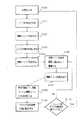
図3は、図2の構成における処理の流れ図である。LEDが発光したとき(ステップS101)、偶数ラインで受光し(ステップS102)、LEDが発光していないとき(ステップS103)、奇数ラインで受光する(ステップS104)。このようにすると、ちょうど、図2のように、偶数ラインに発光時の受光した電荷が蓄積され、奇数ラインに非発光時に受光した電荷が蓄積される。それを、差分回路18を介して読み出す。
【0038】
まず、奇数ライン、つまり、非発光時の受光レベルが差分回路に蓄積される(ステップS106)。つぎに、偶数ライン、つまり、発光時の受光レベルが差分回路18に読み出され(ステップS107)、発光時と非発光時の差分のみが出力される(ステップS108) 。これがアナログ信号処理回路に入力される(ステップS109)。
【0039】
このような動作を、垂直方向にすべてのラインを転送し終わるまで続ける。
転送が終了したら、もう一度、発光し、受光するという動作を続行する。
以上のような動作により、例えば、図4のような、反射光画像(反射光の強さは距離の2乗に反比例するので、実質的には3次元画像)が取得できる。
【0040】
(実施例2)
図2では、イメージセンサを用いて光源の物体反射光画像を得る装置について述べた。しかし、この物体の形状を容易に得られる反射光画像と、通常のカメラで撮るような画像(可視光画像と呼ぶ)を同時に得たいという要求が存在する。このようなことが実現すれば、例えば、可視光画像の中から人間の体や顔だけを切り出すことが容易に行える。
【0041】
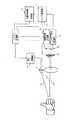
<図5の説明>
図5は反射光画像と可視光画像を同時に得る事のできる装置の構成例を示している。ここでは光学系とイメージセンサを、反射光画像用、可視光画像用に2種類用意している。
【0042】
反射光画像用の受光センサ1は図2で述べたような構成をしている。またイメージセンサ1の前に光源の波長光のみを通過させる光学バンドパスフィルタ2がある。これは光源からの物体反射光5のみを通過させ、それ以外の例えば照明光やその物体反射光4を反射する。
【0043】
一方、可視光画像用のセンサ22は通常の撮像カメラに用いられるようなCCDイメージセンサあるいはCMOSイメージセンサなどを用いることができる。可視光画像用のセンサの前には、光源からの物体反射光を反射させる光学フィルタ23を配置するのが適当である。ただし、この光源の物体反射光が大きな影響を与えない場合、例えば通常、撮像カメラで用いられる赤外光カットフィルタで十分である場合やセンサの分光感度特性によりその光源に対する感度が低いような場合には、この光学フィルタを省いても構わない。
【0044】
これら2つのセンサでの撮像を同時に行うことによって、切り出されたオブジェクトなどの、より高度な情報を得ることができるが、単純に反射光画像だけ、可視光画像だけを撮像する目的でも使うことができる。
【0045】
この構成の場合、反射光画像用のセンサと可視光画像用のセンサは近いところに配置されるので、ほぼ位置ずれの無い画像が得られる。しかし厳密にはわずかな位置ずれは存在し、また物体が近いときにはそれは顕著となる。
【0046】
(実施例2の変形例)
<図6の説明>
図6はこのような位置ずれが起こらないように構成した例である。ここでは光学系を、反射光画像用と可視光画像用で共有する。光学系を通過した光は、例えばダイクロイックミラー28で、光源の物体反射光29とそれ以外の光30とに分けられる。ダイクロイックミラーとは特定波長の光を通過させそれ以外を反射させ、光を波長によって分割するものである。図6では、物体反射光の波長光を通過させ、それ以外を反射させるミラーを用いている。この構成により、厳密に光軸の一致した2枚の画像、すなわち反射光画像と可視光画像を得る事ができる。
【0047】
ここではダイクロイックミラーを用いた例を挙げたが、これに限らず光を光源の物体反射光とそれ以外の光とに分け、重なり合わない位置に配置された2つのイメージセンサに入射させることができるものであれば良い。
【0048】
(実施例3)
<図7の説明>
図5、6では、反射光画像用、可視光画像用の2つのセンサを用いていたが、これをひとつのセンサで行うことができれば、より低コスト化を実現できる。図7はそのひとつの構成例を示している。スライドして動かすことが可能な光学フィルタ31がレンズ32とセンサ33の間に配置されている。
【0049】
このフィルタは半分に光源の波長光のみを通過させるバンドパスフィルタが、もう半分にはこの波長光を遮断し可視光を通過させる光学フィルタが入っている。このフィルタをスライドすることにより、センサに到達する光を光源の物体反射光のみにしたり、可視光のみにしたりすることができる。この場合、ひとつのイメージセンサで反射光画像と可視光画像の両方を撮像できる必要がある。これを次に述べる。
【0050】
図8はCMOSイメージセンサでよく用いられるカラーフィルタの配列である。このように赤成分を通過させる「R」、緑成分を通過させる「G」、青成分を通過させる「B」が配列している。可視光画像を撮像する場合には、そのまま各セルの出力を取り出す。差分回路は動作させないかあるいは各セルの固定パタンノイズを除去するためにのみ用いる。固定パタンとは各セルごとに一定した値を持つ固定ノイズのことである。
【0051】
反射光画像を得る時にはセンサの動作を変える。例えば「G」のセルのみを用い、例えばG1のセルに非発光時蓄積を行い、G2のセルに発光時蓄積を行い、その差を差分回路で取り出せば良い。したがって、Gのセルはその撮像制御を2系統に分け、独立に撮像できるようにする必要がある。
【0052】
例えば、G1、G3、G5、G7のセル群とG2、G4、G6、G8のセル群は独立に撮像できる。この場合、可視光画像と反射光画像の画像解像度は異なる。可視光画像は4画素(Gが2つ、RとBがひとつづつ)でカラーの1画素を構成するので図8では4x4画素である。G1とG2の差分を取り、G3とG4の差分を取り、これらを足しあわせると、すなわち、GG1〜G4で反射光画像の1画素を作る場合、解像度は縦方向に半分、横方向は同じになる。G1〜G8で反射光画像の1画素を作る場合は、縦横方向共に解像度は半分になる(図の場合2x2)。
【0053】
反射光画像を得る場合に、「G」のみのセルを用いる例を示したが、R、G、Bの3種類のセルで光源波長の分光感度がほぼ同じである場合は、この4画素を使って反射光画像の1画素を作ることができる。例えば、G1、R1に非発光時蓄積を行い、B1、G3に発光時蓄積を行い、B1とG1の差分とG3とR1の差分を足しあわせると、可視光画像と同じ解像度の反射光画像を得ることができる。さらにB1とG1の差分とG3とR1の差分をそれぞれひとつずつの反射光画像の画素と見れば、可視光画像に対して横方向の解像度を倍にすることもできる。
【0054】
(実施例3の変形例)
<図9の説明>
反射光画像を作るために「G」のセルのみしか使えないとしても、可視光画像と同じ解像度の反射光画像を得ることはできる。図9のようなフィルタ配列にすれば、G1に非発光時蓄積、G2に発光時蓄積を行うことで、その差分を取り出すことができる。差分回路は通常同じ列の画素についてのみ差分を行えるよう構成するので、図8のようなフィルタ配列にするとG1とG3の差分を取り出すのは難しいが、図9のG1、G2の差分であれば容易に取り出せる。
【0055】
<制御の切り替えについて>
以上述べたような反射光画像を得るための制御は、可視光画像を得るための制御とは異なるため、センサの制御を切り替える必要がある。これはスイッチ、あるいはソフトウエア(この装置をPCにつないで使う場合)で、明示的に制御を切り替えても良いが、フィルタをスライドすることによりスイッチがオン、オフするような機構を備えておいて、フィルタがどちらの位置にあるかを自動的に認識し、それによって制御を切り替えても良い。
【0056】
図7の構成の場合、反射光画像と可視光画像を別々に得ることは容易であるが、同時に得ることは難しい。光学フィルタを高速で移動させるような機構を付け加えれば可能である。半円ずつにそれぞれの光学フィルタを載せた円形のフィルタを回転させる方法もある。
【0057】
(実施例4)
<図10の説明>
図10は、ひとつのセンサで反射光画像と可視光画像の両方の撮像を同時に得ることができる別の構成例である。図6で用いたのと同様のダイクロイックミラーなどの光線分離手段34を用いて、まず光源の物体反射光とそれ以外の光とに分ける。このそれぞれに光を通過させるか遮断させるかを選択できるシャッタ手段34,35を設け、シャッタを通過した後の光をまたひとつに合成し、光学センサ38に導く。
【0058】
シャッタ手段としては液晶パネルなどを用いることができる。液晶パネルなどの駆動は非機械的に行えるので、機械式機構を用いるよりは信頼性が高い。
この図では、光源の物体反射光39は遮断され、それ以外の光40は通過できる状態になっている。逆の状態では、物体反射光はセンサまで到達し、可視光は途中のシャッタで遮断される。
【0059】
(実施例4の変形例1)
<図11の説明>
図10では、2つに分けた光をそれぞれシャッタ手段を経て再合成したが、フィルタ特性をダイナミックに変えることのできる素子を用いれば、光路を分ける必要はない。図11では、レンズとセンサの間に、
(1)光源波長のみを通過させる
(2)可視光のみを通過させる
という2つの状態を切り替えられる素子41が入っている。この素子の状態を切り替えるだけで2種類の画像を撮像することができる。図では、光源の物体反射光39は遮断され、それ以外の光40は通過できる状態になっている。逆の状態では、物体反射光はセンサまで到達し、可視光は途中のシャッタで遮断される。
【0060】
また、
(1)光源波長のみを通過させる
(2)すべての光を通過させる
という2つの状態を切り替えられる素子と、
(1)可視光のみを通過させる
(2)すべての光を通過させる
という2つの状態を切り替えられる素子があれば、これらを重ねることによっても同様の構成を実現できる。
【0061】
(実施例4の変形例2)
<図12の説明>
センサのカラーフィルタを特殊な構成にすることによって、ひとつのセンサで反射光画像と可視光画像を得ることができる。図9は一般的なカラーフィルタの配列の一例であるが、図12のような配列にすることによって、セルを反射光画像用のセルと可視光画像用のセルに分けることができる。この図のセルで「H」とあるのは、光源の波長のみを通過させるフィルタを付けたセルである。R、G、Bのセルは可視光撮像用に使い、Hを反射光画像撮像用に使う。
【0062】
例えば、H1、H3で非発光時蓄積を行い、H2、H4で発光時蓄積を行う。H1〜H4までのセルで反射光画像の1画素を作れば、可視光画像と同じ解像度の反射光画像が得られる。通常の撮像カメラには赤外光成分をカットするためのフィルタを用いている。光源として近赤外光などを用いる場合は、フィルタの影響を考えて強く発光するか、あるいは赤外カットフィルタを可視光画像用セルの上にのみ取り付ける。
【0063】
(実施例4の変形例3)
<図13の説明>
図13は別のフィルタの配列例である。図12に比べ、縦方向の解像度は倍になっており、横方向は3分の2になっている。より解像度の高い画像を求めるならばこちらの配列にするのもよい。
【0064】
以上のような本願発明は、専用のハードウェアを用いずとも、汎用のプロセッサを用いたソフトウェアによる処理で実現することができる。例えば、図3の処理はコンピュータプログラムを用いて実現でき、これをフロッピーディスクやCD−ROMなどの記録媒体を通じてコンピュータに導入して実行させることにより、本願発明を実施することができる。
【0065】
【発明の効果】
以上のように、本願発明によれば、汎用的なイメージセンサを使って反射光画像を取得でき、汎用なセンサを使えるので装置の低コスト化が実現できる。
また本願発明によれば、通常画像中から物体のみを背景から切り出すなどの高度な画像処理を容易に実現できる。
さらに本願発明によれば、より低コストで、反射光画像とそれ以外の光による画像を同時に得ることができる。
【図面の簡単な説明】
【図1】イメージセンサで反射光画像を取得するための構成例の図である。
【図2】イメージセンサで反射光画像を取得するためのより詳細な構成例の図である。
【図3】イメージセンサで反射光画像を取得するための動作フローの図である。
【図4】取得された反射光画像の例
【図5】物体反射光による画像と、それ以外の光による画像を同時に取得できる装置の構成例の図である。
【図6】物体反射光による画像と、それ以外の光による画像を同時に取得できる装置の構成例の図である。
【図7】物体反射光による画像と、それ以外の光による画像を取得できる装置の構成例の図である。
【図8】物体反射光による画像と、それ以外の光による画像を取得できる装置のイメージセンサ上のフィルタ構成の例の図である。
【図9】物体反射光による画像と、それ以外の光による画像を取得できる装置のイメージセンサ上のフィルタ構成の例の図である。
【図10】物体反射光による画像と、それ以外の光による画像を同時に取得できる装置の構成例の図である。
【図11】物体反射光による画像と、それ以外の光による画像を同時に取得できる装置の構成例の図である。
【図12】物体反射光による画像と、それ以外の光による画像を同時に取得できる装置のイメージセンサ上のフィルタ構成の例の図である。
【図13】物体反射光による画像と、それ以外の光による画像を同時に取得できる装置のイメージセンサ上のフィルタ構成の例の図である。
【図14】
従来の3次元データ入力装置の例を示す図である。
【符号の説明】
1…イメージセンサ、2…光学フィルタ、3…レンズ、
4…可視光などの光源の物体反射光以外の光、
5…光源の物体反射光、6…撮像対象物体、7…光源、
8…発光制御部、9…アナログ信号処理回路、
10…制御信号生成装置、11…システム制御部、
12…A/D変換回路、13…反射光画像処理部、
14…光源の光、15…垂直選択回路、17…水平選択回路、
18…差分回路、19…非発光時蓄積用セル、20…発光時蓄積用セル、
22…イメージセンサ、28…光の分割手段、31…フィルタ切り替え手段、
35…光線遮断手段,36…光線遮断手段、41…特性可変な光学フィルタ[0001]
BACKGROUND OF THE INVENTION
The present invention relates to an information input device, an information input method, and a recording medium for inputting information in a three-dimensional space.
[0002]
[Prior art]
As an input device to a computer, a mouse is overwhelmingly used. However, what you can do with the mouse is moving the cursor, selecting menus, and so on. It serves only as a two-dimensional pointing device. Since a mouse can handle two-dimensional information, it is difficult to select an object having a depth such as an object in a three-dimensional space. Also, when creating an animation, it was difficult for the mouse to make a natural movement to add movement to the character.
[0003]
In order to compensate for the difficulty of pointing in a three-dimensional space, a three-dimensional pointing device has been developed. For example, in a three-dimensional pointing device as shown in FIG. 14, the front of the center round means is pushed, the center is pushed, the rear is pushed, the whole round means is lifted, the whole is turned to the right, and the whole is turned to the left. In addition, six operations are possible and there are six degrees of freedom. By assigning these six degrees of freedom, the position (x, y, z) and orientation (x axis, y axis, z axis) of the cursor in the three-dimensional space can be controlled, or the viewpoint position (x , Y, z) and direction (x axis, y axis, z axis) can be controlled.
[0004]
However, there is a problem that the cursor and viewpoint cannot be controlled as expected when actually operated. For example, if you try to turn left or right, you push forward or backward, and the cursor moves in an unexpected direction or the viewpoint moves.
[0005]
For such a three-dimensional pointing device, devices that use hand gestures and gestures have been developed. It is called a data glove, data suit, or cyber glove. For example, a data glove is a glove-like device, and an optical fiber runs on the surface. The optical fiber passes through the finger joint, and the light conduction is changed by bending the finger. By measuring this light conduction, it is possible to know how much the finger joint is bent. The position of the hand itself in the three-dimensional space is measured by a magnetic sensor on the back of the hand. If you decide the gesture and the corresponding instructions, such as moving forward with your index finger, you can use the data glove to change the viewpoint in various ways in the 3D space (walk through) Can be said).
[0006]
However, there are some problems. First, the price is expensive and it is difficult to use for home use. Since the angle of the finger joint is measured, for example, it is assumed that only the index finger is extended, and the other fingers are defined to be in a bent state as a forward instruction. Even if you actually extend your finger to the mouth, the angle of the second joint of the index finger is rarely 180 degrees, so unless you make a means of play, It is difficult to recognize that you are extending. In addition, wearing a data glove impedes natural operation. In addition, it is not easy to use because it is necessary to calibrate the light conduction state with the hand open and closed each time it is worn. Moreover, since an optical fiber is used, there is a problem that if it is continuously used, it is close to a consumable item such as the fiber being cut off. In addition, although it is an expensive and time-consuming device, if the size of the glove is not exactly the same, it will deviate from the calibrated value when it is used. It is difficult to recognize hand gestures. In this way, due to various problems, the data glove is not as popular as it was originally expected, even though it was the device that triggered VR (virtual reality) technology. Also, the price has not been lowered, and there are many problems in terms of usability.
[0007]
On the other hand, some attempts have been made to input hand gestures and gestures without wearing special devices such as data gloves. For example, research has been made to recognize a hand shape by analyzing a moving image such as a video image.
[0008]
However, these methods have a problem that it is difficult to cut out only the hand in the case of recognizing the target image or hand gesture from the background image. For example, consider the case of cutting out using colors. Since the hand color is skin color, a method of cutting out only the means of skin color is conceivable. However, if there are beige clothes or walls on the background, it is difficult to identify the skin color. Further, even if adjustment is made so that beige and flesh color can be distinguished, if the illumination changes, the color tone will change, so it is difficult to cut out regularly.
[0009]
In order to escape from such a problem, a measure has been taken to make it easy to cut out by placing a restriction on the background image, such as placing a blue matte in the background. Alternatively, a measure is taken such that the fingertip is colored so that it can be easily cut out from the background, or a colored ring is fitted. However, such restrictions are not realistic and have been used experimentally, but have not yet been put into practical use.
[0010]
In addition, the video image recognition processing such as clipping as described above requires a large amount of calculation. For this reason, the current situation is that a current personal computer cannot process 30 images generated per second. Therefore, it is impossible to perform motion capture by processing video images in real time.
[0011]
There is a device for inputting a distance image called a range finder. As a typical principle, spot light or slit light is irradiated on a target object, and the principle of triangulation is obtained from the light receiving position of the reflected light. In order to obtain two-dimensional distance information, spot light or slit light is mechanically scanned. Although this apparatus can generate a very high-precision distance image, on the other hand, the structure of the apparatus becomes large and the cost is high. Moreover, it takes time to input, and it is difficult to perform processing in real time.
[0012]
There are also devices that attach color markers or light emitting parts to parts of the hand or body, detect them by image, and capture the shape and movement of the hand / body, and some have been put into practical use. However, considering the convenience of the user, it is a major disadvantage that the device must be mounted every time it is operated, and the application range is very limited. In addition, as seen in the example of the data glove, the durability of a device that is used by attaching the device to a movable part such as a hand is likely to be a problem.
[0013]
Next, apart from the input devices as described above, the problems of the camera technology with respect to the conventional technology will be described. In the conventional camera technology, in order to perform character composition (chroma key) on the background, it is necessary to capture the character with a blue background in advance and to easily cut out the character. For this reason, there were restrictions on the shooting location, such as a studio that can shoot with a blue background. Alternatively, in order to cut out a character from a video shot without a blue background, the cutout range of the character has to be manually edited for each frame, which is very troublesome.
[0014]
Similarly, in order to generate a character in a three-dimensional space, a method is used in which a three-dimensional model is created in advance and a character photograph is pasted (texture mapping). However, generation of a three-dimensional model and texture mapping are time-consuming, and it can hardly be used except for applications that may cost money such as movie production.
[0015]
In order to solve such a problem, for example, a system for extracting a reflected light image and acquiring a distance image as disclosed in Japanese Patent Application No. 9-299648 has been developed. However, this method has a problem that the hue information of the object cannot be obtained in order to extract the reflected light image. For this reason, the conventional imaging camera, the camera which cuts out a reflected light image, and two cameras have arisen.
[0016]
[Problems to be solved by the invention]
There was no direct instruction type input device that can easily input gestures and movements without wearing a special device. In particular, there has been no simple device that can easily perform pointing and changing the viewpoint in a three-dimensional space. In addition, the user's gestures and movements cannot be used as they are to add natural movement to animated characters.
[0017]
Furthermore, conventional cameras cannot cut out only a specific character or easily input character depth information.
In the method for improving this, a special sensor array is used, and there is a problem that the price becomes expensive.
[0018]
In addition, in the imaging method that solves such a problem, only the reflected light image is acquired, so there is a problem that hue information cannot be obtained and two conventional cameras are required.
[0019]
[Means for Solving the Problems]
To solve the above problems,Timing signal generation means for generating a pulse signal or modulation signal, light emission means for emitting light based on a signal from the timing signal generation means, and light emission by the light emission means by synchronizing with a signal from the timing signal generation means First light receiving means for receiving reflected light from the object of the light, second light receiving means for blocking visible light reflected by the light emission of the light emitting means and receiving visible light, and the first light receiving means, And detecting means for simultaneously detecting a reflected light image and a visible light image of the object from the second light receiving means.It is characterized by that.
[0028]
Also, generate a pulse signal or modulation signal,Based on the timing of generating the pulse signal or modulation signalBy making the light emitting means emit light and synchronizing with the pulse signal or modulation signal,Light emitted by the light emitting meansReceiving light reflected by an object of light, said light emitting meansVisible light by blocking reflected light from objectsReceive light,The reflected light image and the visible light image of the object are simultaneously detected from the received reflected light and the visible light.It is characterized by that.
[0029]
Also, a recording medium on which a computer executable program for image acquisition is recorded, generating a pulse signal or a modulation signal, causing the light emitting means to emit light based on the timing for generating the pulse signal or the modulation signal,By synchronizing with the pulse signal or the modulation signal, the reflected light from the object emitted by the light emitting means is received, the reflected light from the object emitted by the light emitting means is blocked, and the visible light is received,
The reflected light image and the visible light image of the object are simultaneously detected from the received reflected light and the visible light.Recording medium on which the program is recorded
[0030]
DETAILED DESCRIPTION OF THE INVENTION
Example 1
Hereinafter, embodiments of the present invention will be described in detail with reference to the drawings.
<Description of FIG. 1>
FIG. 1 shows a configuration example of an apparatus for obtaining a reflected light image using an image sensor. The light
[0031]
The light source 7 is preferably a light source that operates stably over a long period of time, such as an LED, and responds at high speed. The light receiving sensor 1 performs at least two imaging operations in synchronization with the light emission. One imaging is performed simultaneously with light emission, and light including the object reflected light 5 of the light 14 of the light source is received. The other imaging is performed when the light source is not emitting light, and light that does not include object reflected light of the light source is received. This sensor can output the difference between the two imaging operations. That is, by obtaining this difference, only the object reflected light of the light from the light source is output.
[0032]
Between the lens 3 and the sensor 1 is a filter 2 that blocks unnecessary light. For example, an optical bandpass filter that passes only the light source wavelength. For this reason, much unnecessary light 4 such as illumination light does not enter the sensor. However, since external light such as illumination light often has a component having the same wavelength as the light source wavelength, differential operation is performed.
[0033]
The sensor output is converted into digital data by the A /
[0034]
<Description of FIG. 2>
FIG. 2 is a diagram describing the image sensor of the light receiving sensor portion of FIG. 1 in more detail. In the image sensor shown in FIG. 2, the pixel position is given by the
[0035]
The difference circuit 18 is a circuit that once accumulates the charge amount and outputs a difference from the next input charge amount. This image sensor can control the imaging operation of even and odd rows independently. The even rows are used as cells that receive light when the light source emits light, and the odd rows are used as cells that receive light when the light source is not emitting light. That is, when the light source emits light, imaging is performed with even-numbered rows of cells, and when not emitting light, imaging is performed with odd-numbered rows of cells. Hereinafter, the former is referred to as a
[0036]
For example, the difference circuit 18 operates as follows. First, the non-light-emission accumulated cells in the first row are read and stored in the difference circuit for one row. Next, the accumulated cells at the time of light emission in the second row are read, and the difference from the received light amount in the first row stored in the difference circuit is output. The subsequent processing is the same as that described in FIG.
[0037]
FIG. 3 is a flowchart of processing in the configuration of FIG. When the LED emits light (step S101), light is received by the even line (step S102), and when the LED is not emitting light (step S103), the light is received by the odd line (step S104). In this way, as shown in FIG. 2, charges received during light emission are accumulated in even lines, and charges received during non-light emission are accumulated in odd lines. It is read out via the difference circuit 18.
[0038]
First, the odd-numbered line, that is, the light reception level when no light is emitted is accumulated in the difference circuit (step S106). Next, the even lines, that is, the light reception level at the time of light emission is read to the difference circuit 18 (step S107), and only the difference between the light emission time and the non-light emission time is output (step S108). This is input to the analog signal processing circuit (step S109).
[0039]
Such an operation is continued until all lines are transferred in the vertical direction.
When the transfer is completed, the operation of emitting light and receiving light again is continued.
By the above operation, for example, a reflected light image (substantially a three-dimensional image is obtained because the intensity of the reflected light is inversely proportional to the square of the distance) as shown in FIG.
[0040]
(Example 2)
In FIG. 2, an apparatus for obtaining an object reflected light image of a light source using an image sensor has been described. However, there is a demand to simultaneously obtain a reflected light image that can easily obtain the shape of the object and an image (referred to as a visible light image) that can be taken with a normal camera. If this is realized, for example, it is possible to easily cut out only a human body or face from a visible light image.
[0041]
<Description of FIG. 5>
FIG. 5 shows a configuration example of an apparatus that can obtain a reflected light image and a visible light image at the same time. Here, two types of optical systems and image sensors are prepared for reflected light images and visible light images.
[0042]
The light receiving sensor 1 for the reflected light image has a configuration as described in FIG. Further, an optical bandpass filter 2 that allows only the wavelength light of the light source to pass is provided in front of the image sensor 1. This allows only the object reflected light 5 from the light source to pass, and reflects other illumination light or the object reflected light 4, for example.
[0043]
On the other hand, the visible
[0044]
By performing imaging with these two sensors at the same time, it is possible to obtain more advanced information such as a clipped object, but it can also be used for the purpose of simply capturing only reflected light images or visible light images. it can.
[0045]
In the case of this configuration, the reflected light image sensor and the visible light image sensor are arranged close to each other, so that an image with almost no displacement can be obtained. However, strictly speaking, there is a slight misalignment, and it becomes noticeable when the object is close.
[0046]
(Modification of Example 2)
<Description of FIG. 6>
FIG. 6 shows an example in which such misalignment does not occur. Here, the optical system is shared for the reflected light image and the visible light image. The light that has passed through the optical system is divided into, for example, an object reflected
[0047]
Although an example using a dichroic mirror is given here, the present invention is not limited to this, and the light can be divided into object reflected light of the light source and other light, and incident on two image sensors arranged at non-overlapping positions. Anything is possible.
[0048]
(Example 3)
<Explanation of FIG. 7>
In FIGS. 5 and 6, two sensors for the reflected light image and the visible light image are used. However, if this can be performed with one sensor, the cost can be further reduced. FIG. 7 shows one configuration example. An
[0049]
This filter includes a band-pass filter that passes only the wavelength light of the light source in half, and an optical filter that blocks the wavelength light and allows visible light to pass through the other half. By sliding this filter, the light reaching the sensor can be made only the object reflected light of the light source or only visible light. In this case, it is necessary to be able to capture both the reflected light image and the visible light image with a single image sensor. This will be described next.
[0050]
FIG. 8 shows an arrangement of color filters often used in CMOS image sensors. In this way, “R” for passing the red component, “G” for passing the green component, and “B” for passing the blue component are arranged. When capturing a visible light image, the output of each cell is taken out as it is. The difference circuit is not operated or is used only for removing fixed pattern noise of each cell. The fixed pattern is fixed noise having a constant value for each cell.
[0051]
When obtaining a reflected light image, the operation of the sensor is changed. For example, only the “G” cell is used. For example, accumulation is performed in the G1 cell when no light is emitted, accumulation is performed in the G2 cell during light emission, and the difference is extracted by a difference circuit. Therefore, it is necessary for the G cell to divide its imaging control into two systems so that imaging can be performed independently.
[0052]
For example, the cell groups G1, G3, G5, and G7 and the cell groups G2, G4, G6, and G8 can be imaged independently. In this case, the image resolutions of the visible light image and the reflected light image are different. The visible light image is 4 × 4 pixels in FIG. 8 because four pixels (two G and one R and B) constitute one color pixel. Taking the difference between G1 and G2, taking the difference between G3 and G4, and adding them together, that is, when making one pixel of the reflected light image with GG1 to G4, the resolution is half in the vertical direction and the horizontal direction is the same Become. When one pixel of the reflected light image is created by G1 to G8, the resolution is halved in both the vertical and horizontal directions (2 × 2 in the figure).
[0053]
In the case of obtaining a reflected light image, an example in which only the cell “G” is used has been shown. However, when the spectral sensitivity of the light source wavelength is almost the same in the three types of cells R, G, and B, these four pixels are It can be used to make one pixel of the reflected light image. For example, accumulation is performed when G1 and R1 are not emitting light, accumulation is performed when B1 and G3 are emitting light, and the difference between B1 and G1 and the difference between G3 and R1 are added together to produce a reflected light image having the same resolution as the visible light image. Obtainable. Further, if the difference between B1 and G1 and the difference between G3 and R1 are regarded as one pixel of the reflected light image, respectively, the resolution in the horizontal direction can be doubled with respect to the visible light image.
[0054]
(Modification of Example 3)
<Description of FIG. 9>
Even if only the “G” cell can be used to create a reflected light image, a reflected light image having the same resolution as the visible light image can be obtained. If the filter arrangement as shown in FIG. 9 is used, the difference can be extracted by performing accumulation at non-light emission in G1 and accumulation at light emission in G2. Since the difference circuit is normally configured so that the difference can be performed only for pixels in the same column, it is difficult to extract the difference between G1 and G3 if the filter arrangement is as shown in FIG. 8, but if the difference is between G1 and G2 in FIG. Easy to take out.
[0055]
<About control switching>
Since the control for obtaining the reflected light image as described above is different from the control for obtaining the visible light image, it is necessary to switch the control of the sensor. This is a switch or software (when this device is connected to a PC) and the control may be switched explicitly, but it has a mechanism that turns the switch on and off by sliding the filter. The position of the filter may be automatically recognized, and the control may be switched accordingly.
[0056]
In the case of the configuration of FIG. 7, it is easy to obtain a reflected light image and a visible light image separately, but it is difficult to obtain them simultaneously. This can be achieved by adding a mechanism for moving the optical filter at high speed. There is also a method of rotating a circular filter in which each optical filter is placed in a semicircle.
[0057]
(Example 4)
<Description of FIG. 10>
FIG. 10 shows another configuration example in which both the reflected light image and the visible light image can be obtained simultaneously with one sensor. First, the light beam separating means 34 such as a dichroic mirror similar to that used in FIG. 6 is used to divide the light into object reflected light and other light. Each of these is provided with shutter means 34 and 35 capable of selecting whether light is allowed to pass or blocked, and the lights after passing through the shutter are combined together and guided to the
[0058]
A liquid crystal panel or the like can be used as the shutter means. Since the liquid crystal panel can be driven non-mechanically, it is more reliable than using a mechanical mechanism.
In this figure, the object reflected
[0059]
(Modification 1 of Example 4)
<Description of FIG. 11>
In FIG. 10, the light divided into two is recombined via the shutter means, but if an element capable of dynamically changing the filter characteristics is used, it is not necessary to divide the optical path. In FIG. 11, between the lens and the sensor,
(1) Only the light source wavelength is allowed to pass
(2) Allow only visible light to pass
The
[0060]
Also,
(1) Only the light source wavelength is allowed to pass
(2) Allow all light to pass
An element that can be switched between two states,
(1) Allow only visible light to pass
(2) Allow all light to pass
If there is an element that can switch between the two states, the same configuration can be realized by overlapping these elements.
[0061]
(Modification 2 of Example 4)
<Description of FIG. 12>
By making the color filter of the sensor special, a reflected light image and a visible light image can be obtained with one sensor. FIG. 9 shows an example of a general color filter arrangement. By arranging the arrangement as shown in FIG. 12, the cells can be divided into a reflected light image cell and a visible light image cell. In the cell of this figure, “H” is a cell provided with a filter that passes only the wavelength of the light source. The R, G, and B cells are used for visible light imaging, and H is used for reflected light image imaging.
[0062]
For example, accumulation is performed when H1 and H3 are not emitting light, and accumulation is performed when H2 and H4 are emitted. If one pixel of the reflected light image is made of cells H1 to H4, a reflected light image having the same resolution as the visible light image can be obtained. A normal imaging camera uses a filter for cutting infrared light components. When near infrared light or the like is used as a light source, light is emitted strongly in consideration of the influence of the filter, or an infrared cut filter is attached only on the visible light image cell.
[0063]
(Modification 3 of Example 4)
<Description of FIG. 13>
FIG. 13 shows another filter arrangement example. Compared to FIG. 12, the resolution in the vertical direction is doubled and the horizontal direction is two-thirds. If you want a higher resolution image, you can use this array.
[0064]
The present invention as described above can be realized by software processing using a general-purpose processor without using dedicated hardware. For example, the processing of FIG. 3 can be realized by using a computer program, and the present invention can be implemented by introducing it into a computer through a recording medium such as a floppy disk or CD-ROM and executing it.
[0065]
【The invention's effect】
As described above, according to the present invention, the reflected light image can be acquired using a general-purpose image sensor, and the general-purpose sensor can be used, so that the cost of the apparatus can be reduced.
Further, according to the present invention, it is possible to easily realize advanced image processing such as cutting out only an object from a background from a normal image.
Furthermore, according to the present invention, a reflected light image and an image by other light can be simultaneously obtained at lower cost.
[Brief description of the drawings]
FIG. 1 is a diagram illustrating a configuration example for acquiring a reflected light image by an image sensor.
FIG. 2 is a diagram showing a more detailed configuration example for obtaining a reflected light image by an image sensor.
FIG. 3 is a diagram of an operation flow for obtaining a reflected light image by an image sensor.
FIG. 4 shows an example of an acquired reflected light image.
FIG. 5 is a diagram illustrating a configuration example of an apparatus that can simultaneously acquire an image based on object reflected light and an image based on other light.
FIG. 6 is a diagram illustrating a configuration example of an apparatus that can simultaneously acquire an image based on object reflected light and an image based on other light.
FIG. 7 is a diagram illustrating a configuration example of an apparatus capable of acquiring an image based on object reflected light and an image based on other light.
FIG. 8 is a diagram illustrating an example of a filter configuration on an image sensor of an apparatus that can acquire an image based on object reflected light and an image based on other light.
FIG. 9 is a diagram illustrating an example of a filter configuration on an image sensor of an apparatus capable of acquiring an image based on object reflected light and an image based on other light.
FIG. 10 is a diagram illustrating a configuration example of an apparatus that can simultaneously acquire an image based on object reflected light and an image based on other light.
FIG. 11 is a diagram illustrating a configuration example of an apparatus that can simultaneously acquire an image based on object reflected light and an image based on other light.
FIG. 12 is a diagram illustrating an example of a filter configuration on an image sensor of an apparatus that can simultaneously acquire an image based on object reflected light and an image based on other light.
FIG. 13 is a diagram illustrating an example of a filter configuration on an image sensor of an apparatus that can simultaneously acquire an image based on object reflected light and an image based on other light.
FIG. 14
It is a figure which shows the example of the conventional three-dimensional data input device.
[Explanation of symbols]
1 ... image sensor, 2 ... optical filter, 3 ... lens,
4. Light other than object reflected light from a light source such as visible light,
5 ... Object reflected light of light source, 6 ... Object to be imaged, 7 ... Light source,
8 ... Light emission control unit, 9 ... Analog signal processing circuit,
10 ... control signal generator, 11 ... system control unit,
12 ... A / D conversion circuit, 13 ... reflected light image processing unit,
14 ... Light of light source, 15 ... Vertical selection circuit, 17 ... Horizontal selection circuit,
18... Differential circuit, 19... Non-light emitting storage cell, 20...
22 ... Image sensor, 28 ... Light splitting means, 31 ... Filter switching means,
35 ... light blocking means, 36 ... light blocking means, 41 ... optical filter with variable characteristics
Claims (10)
Translated fromJapanese前記タイミング信号生成手段からの信号に基づいて発光する発光手段と、
前記タイミング信号生成手段からの信号と同期することにより、前記発光手段で発光した光の物体による反射光を受光する第1の受光手段と、
前記発光手段の発光による物体の反射光を遮断し、可視光を受光する第2の受光手段と、
前記第1の受光手段と、前記第2の受光手段とから、物体の反射光画像と可視光画像とを同時に検出する検出手段と具備したことを特徴とする画像取得装置。Timing signal generating means for generating a pulse signal or a modulation signal;
Light emitting means for emitting light based on a signal from the timing signal generating means;
A first light receiving means for receiving reflected light from an object of light emitted by the light emitting means by synchronizing with a signal from the timing signal generating means;
A second light receiving means for blocking visible light reflected by light emitted from the light emitting means and receiving visible light;
An image acquisition apparatus comprising: a detection unit that simultaneously detects a reflected light image and a visible light image of an object from the first light receiving unit and the second light receiving unit.
前記第2の受光手段が受光する可視光を結像するための第2の結像手段とを具備することを特徴とする請求項1に記載の画像取得装置。First imaging means for imaging object reflected light received by the first light receiving means;
The image acquisition apparatus according to claim 1, further comprising: a second image forming unit configured to form an image of visible light received by the second light receiving unit.
パルス信号もしくは変調信号を発生させるタイミング信号生成手段と、
前記エリアイメージセンサの受光セルの受光を行毎個別に制御するための制御信号を、前記タイミング信号生成手段からの信号に基づいて生成する制御信号生成手段と、
前記タイミング信号生成手段からの信号に基づいて発光する発光手段と、
前記制御信号に基づいて、前記発光手段の発光時に受光した行の受光量と非発光時に受光した行の受光量の差分を出力する差分手段と、
前記差分手段で出力した差分から物体の反射光画像を検出する検出手段と、
前記エリアイメージセンサに受光される光のうち、前記発光手段の発光する光による物体の反射光のみを通過する反射光通過フィルタと、
前記エリアイメージセンサに受光される光のうち、前記発光手段の発光する光による物体の反射光を遮断して可視光を通過する可視光通過フィルタと、
前記エリアイメージセンサで受光する際に光を通過させる前記反射光通過フィルタと前記可視光通過フィルタのうちの一方を選択する選択手段とを具備し、
前記制御信号生成手段は、前記エリアイメージセンサが前記発光手段で発光した光による物体の反射光を受光するための制御信号と、可視光を受光するための制御信号を選択して出力することを特徴とする画像取得装置。An area image sensor in which light receiving cells arranged in an array form receive light individually for each row;
Timing signal generating means for generating a pulse signal or a modulation signal;
Control signal generating means for generating a control signal for individually controlling the light reception of the light receiving cells of the area image sensor based on a signal from the timing signal generating means;
Light emitting means for emitting light based on a signal from the timing signal generating means;
Based on the control signal, a difference unit that outputs a difference between a light receiving amount of the row received when the light emitting unit emits light and a light receiving amount of the row received when not emitting light,
Detecting means for detecting a reflected light image of the object from the difference output by the difference means;
Of the light received by the area image sensor, a reflected light passing filter that passes only the reflected light of the object by the light emitted by the light emitting means,
A visible light passing filter that blocks the reflected light of the object due to the light emitted by the light emitting means out of the light received by the area image sensor, and passes visible light;
Comprising: a selecting means for selecting one of the reflected light passing filter and the visible light passing filter that allow light to pass through when being received by the area image sensor;
The control signal generating means selects and outputs a control signal for receiving reflected light of an object by light emitted from the light emitting means by the area image sensor and a control signal for receiving visible light. A characteristic image acquisition device.
パルス信号もしくは変調信号を発生させるタイミング信号生成手段と、
前記エリアイメージセンサの受光セルの受光を行毎個別に制御するための制御信号を、前記タイミング信号生成手段からの信号に基づいて生成する制御信号生成手段と、
前記タイミング信号生成手段からの信号に基づいて発光する発光手段と、
前記制御信号に基づいて、前記発光手段の発光時に受光した行の受光量と非発光時に受光した行の受光量の差分を出力する差分手段と、
前記差分手段で出力した差分から物体の反射光画像を検出する検出手段と、
前記エリアイメージセンサに受光される光のうち、前記発光手段の発光する光による物体の反射光のみを通過する反射光通過フィルタと、
前記エリアイメージセンサに受光される光のうち、前記発光手段の発光する光による物体の反射光を遮断して可視光を通過する可視光通過フィルタと、
前記タイミング信号生成手段からの信号と同期して、前記反射光通過フィルタと、可視光通過フィルタの切替えを行う切替手段を具備し、
前記制御信号生成手段は、前記エリアイメージセンサが前記発光手段で発光した光による物体の反射光を受光するための制御信号と、可視光を受光するための制御信号を選択して出力することを特徴とする画像取得装置。An area image sensor in which light receiving cells arranged in an array form receive light individually for each row;
Timing signal generating means for generating a pulse signal or a modulation signal;
Control signal generating means for generating a control signal for individually controlling the light reception of the light receiving cells of the area image sensor based on a signal from the timing signal generating means;
Light emitting means for emitting light based on a signal from the timing signal generating means;
Based on the control signal, a difference unit that outputs a difference between a light receiving amount of the row received when the light emitting unit emits light and a light receiving amount of the row received when not emitting light,
Detecting means for detecting a reflected light image of the object from the difference output by the difference means;
Of the light received by the area image sensor, a reflected light passing filter that passes only the reflected light of the object by the light emitted by the light emitting means,
A visible light passing filter that blocks the reflected light of the object due to the light emitted by the light emitting means out of the light received by the area image sensor, and passes visible light;
In synchronization with the signal from the timing signal generating means, comprising a switching means for switching the reflected light pass filter and the visible light pass filter,
The control signal generating means selects and outputs a control signal for receiving reflected light of an object by light emitted from the light emitting means by the area image sensor and a control signal for receiving visible light. A characteristic image acquisition device.
パルス信号もしくは変調信号を発生させるタイミング信号生成手段と、
前記エリアイメージセンサの受光セルの受光を行毎個別に制御するための制御信号を、前記タイミング信号生成手段からの信号に基づいて生成する制御信号生成手段と、
前記タイミング信号生成手段からの信号に基づいて発光する発光手段と、
前記制御信号に基づいて、前記発光手段の発光時に受光した行の受光量と非発光時に受光した行の受光量の差分を出力する差分手段と、
前記差分手段で出力した差分から物体の反射光画像を検出する検出手段と、
前記発光手段で発光した光による物体の反射光と可視光を分光するための分光手段と、
分光された前記光の光路上で、この光の通過/遮断を選択する選択手段と、
前記分光手段で分光された2つの光を合成する合成手段を具備し、
前記制御信号生成手段は、前記エリアイメージセンサが前記発光手段で発光した光による物体の反射光を受光するための制御信号と、可視光を受光するための制御信号を選択して出力することを特徴とする画像取得装置。An area image sensor in which light receiving cells arranged in an array form receive light individually for each row;
Timing signal generating means for generating a pulse signal or a modulation signal;
Control signal generating means for generating a control signal for individually controlling the light reception of the light receiving cells of the area image sensor based on a signal from the timing signal generating means;
Light emitting means for emitting light based on a signal from the timing signal generating means;
Based on the control signal, a difference unit that outputs a difference between a light receiving amount of the row received when the light emitting unit emits light and a light receiving amount of the row received when not emitting light,
Detecting means for detecting a reflected light image of the object from the difference output by the difference means;
A spectroscopic means for spectroscopically reflecting the reflected light and visible light of the object by the light emitted from the light emitting means;
A selection means for selecting passage / blocking of the light on the optical path of the split light;
Comprising a synthesis means for synthesizing two lights separated by the spectroscopic means,
The control signal generating means selects and outputs a control signal for receiving reflected light of an object by light emitted from the light emitting means by the area image sensor and a control signal for receiving visible light. A characteristic image acquisition device.
パルス信号もしくは変調信号を発生させるタイミング信号生成手段と、
前記エリアイメージセンサの受光セルの受光を行毎個別に制御するための制御信号を、前記タイミング信号生成手段からの信号に基づいて生成する制御信号生成手段と、
前記タイミング信号生成手段からの信号に基づいて発光する発光手段と、
前記制御信号に基づいて、前記発光手段の発光時に受光した行の受光量と非発光時に受光した行の受光量の差分を出力する差分手段と、
前記差分手段で出力した差分から物体の反射光画像を検出する検出手段を具備し、
前記エリアイメージセンサの受光セルは前記発光手段の発光する光による物体の反射光を受光するためのセルと、前記発光手段の発光による物体の反射光を遮断し、可視光を受光するためのセルによって構成されることを特徴とする画像取得装置。An area image sensor in which light receiving cells arranged in an array form receive light individually for each row;
Timing signal generating means for generating a pulse signal or a modulation signal;
Control signal generating means for generating a control signal for individually controlling the light reception of the light receiving cells of the area image sensor based on a signal from the timing signal generating means;
Light emitting means for emitting light based on a signal from the timing signal generating means;
Based on the control signal, a difference unit that outputs a difference between a light receiving amount of the row received when the light emitting unit emits light and a light receiving amount of the row received when not emitting light,
Comprising a detecting means for detecting a reflected light image of the object from the difference output by the difference means,
The light receiving cell of the area image sensor is a cell for receiving the reflected light of the object by the light emitted from the light emitting means, and a cell for blocking the reflected light of the object by the light emitted from the light emitting means and receiving visible light An image acquisition device comprising:
パルス信号もしくは変調信号を発生させるタイミングに基づいて発光手段を発光させ、
パルス信号もしくは変調信号と同期することにより、前記発光手段で発光した光の物体による反射光を受光し、
前記発光手段の発光による物体の反射光を遮断して可視光を受光し、
受光した前記反射光と前記可視光とから、物体の反射光画像と可視光画像とを同時に検出することを特徴とする画像取得方法。Generate a pulse signal or modulation signal,
Based on the timing of generating a pulse signal or modulation signal, the light emitting means emits light,
By synchronizing with the pulse signal or modulation signal, the reflected light from the object of the light emitted by the light emitting means is received,
Visible light is received by blocking reflected light of the object due to light emission of the light emitting means,
An image acquisition method comprising: simultaneously detecting a reflected light image and a visible light image of an object from the received reflected light and the visible light.
パルス信号もしくは変調信号を発生させ、
パルス信号もしくは変調信号を発生させるタイミングに基づいて発光手段を発光させ、
パルス信号もしくは変調信号と同期することにより、前記発光手段で発光した光の物体による反射光を受光し、
前記発光手段の発光による物体の反射光を遮断して可視光を受光し、
受光した前記反射光と前記可視光とから、物体の反射光画像と可視光画像とを同時に検出するプログラムを記録した記録媒体。A recording medium on which a computer executable program for image acquisition is recorded,
Generate a pulse signal or modulation signal,
Based on the timing of generating a pulse signal or modulation signal, the light emitting means emits light,
By synchronizing with the pulse signal or modulation signal, the reflected light from the object of the light emitted by the light emitting means is received,
Visible light is received by blocking reflected light of the object due to light emission of the light emitting means,
A recording medium recording a program for simultaneously detecting a reflected light image and a visible light image of an object from the received reflected light and visible light.
Priority Applications (3)
| Application Number | Priority Date | Filing Date | Title |
|---|---|---|---|
| JP6638298AJP3868621B2 (en) | 1998-03-17 | 1998-03-17 | Image acquisition apparatus, image acquisition method, and recording medium |
| US09/268,645US6714247B1 (en) | 1998-03-17 | 1999-03-16 | Apparatus and method for inputting reflected light image of a target object |
| US10/644,754US7453511B2 (en) | 1998-03-17 | 2003-08-21 | Apparatus and method for inputting reflected light image of a target object |
Applications Claiming Priority (1)
| Application Number | Priority Date | Filing Date | Title |
|---|---|---|---|
| JP6638298AJP3868621B2 (en) | 1998-03-17 | 1998-03-17 | Image acquisition apparatus, image acquisition method, and recording medium |
Publications (2)
| Publication Number | Publication Date |
|---|---|
| JPH11265241A JPH11265241A (en) | 1999-09-28 |
| JP3868621B2true JP3868621B2 (en) | 2007-01-17 |
Family
ID=13314232
Family Applications (1)
| Application Number | Title | Priority Date | Filing Date |
|---|---|---|---|
| JP6638298AExpired - Fee RelatedJP3868621B2 (en) | 1998-03-17 | 1998-03-17 | Image acquisition apparatus, image acquisition method, and recording medium |
Country Status (2)
| Country | Link |
|---|---|
| US (2) | US6714247B1 (en) |
| JP (1) | JP3868621B2 (en) |
Families Citing this family (44)
| Publication number | Priority date | Publication date | Assignee | Title |
|---|---|---|---|---|
| US7298360B2 (en)* | 1997-03-06 | 2007-11-20 | Harmonic Research, Inc. | Body-mounted selective control device |
| JP3868621B2 (en)* | 1998-03-17 | 2007-01-17 | 株式会社東芝 | Image acquisition apparatus, image acquisition method, and recording medium |
| EP1074943A3 (en)* | 1999-08-06 | 2004-03-24 | Canon Kabushiki Kaisha | Image processing method and apparatus |
| KR20020092393A (en)* | 2000-03-21 | 2002-12-11 | 레오나드 레이필 | Multi user retro reflector data input |
| JP3726699B2 (en)* | 2001-04-20 | 2005-12-14 | 日本ビクター株式会社 | Optical imaging device, optical distance measuring device |
| US20030016290A1 (en)* | 2001-07-18 | 2003-01-23 | Oh-Bong Kwon | Multi-functional image sensing device |
| JP3800052B2 (en)* | 2001-08-20 | 2006-07-19 | ソニー株式会社 | Still image capturing apparatus and method |
| JP4451583B2 (en)* | 2001-12-27 | 2010-04-14 | 富士フイルム株式会社 | Imaging apparatus, imaging method, and program |
| US20030147002A1 (en)* | 2002-02-06 | 2003-08-07 | Eastman Kodak Company | Method and apparatus for a color sequential scannerless range imaging system |
| US9007197B2 (en) | 2002-05-20 | 2015-04-14 | Intelligent Technologies International, Inc. | Vehicular anticipatory sensor system |
| GB0311177D0 (en)* | 2003-05-15 | 2003-06-18 | Qinetiq Ltd | Non contact human-computer interface |
| JP2005004181A (en)* | 2003-05-21 | 2005-01-06 | Fujinon Corp | Visible / infrared lens system |
| US8560972B2 (en)* | 2004-08-10 | 2013-10-15 | Microsoft Corporation | Surface UI for gesture-based interaction |
| JP2006053678A (en) | 2004-08-10 | 2006-02-23 | Toshiba Corp | Electronic equipment with universal human interface |
| JP4595135B2 (en)* | 2004-10-07 | 2010-12-08 | 株式会社メガチップス | Distance measuring system and distance measuring method |
| JP4744964B2 (en)* | 2005-07-22 | 2011-08-10 | Hoya株式会社 | Imaging device |
| US8128533B2 (en)* | 2005-12-12 | 2012-03-06 | Ssd Company Limited | Exercise assisting method, exercise appliance, and information processor |
| JP4844121B2 (en)* | 2005-12-27 | 2011-12-28 | 船井電機株式会社 | Image sensor and imaging apparatus |
| JP4797752B2 (en)* | 2006-03-31 | 2011-10-19 | 株式会社デンソー | Operating object extraction device for moving objects |
| US8217895B2 (en) | 2006-04-28 | 2012-07-10 | Mtekvision Co., Ltd. | Non-contact selection device |
| US20080084392A1 (en)* | 2006-10-04 | 2008-04-10 | Siemens Medical Solutions Usa, Inc. | Optical Mouse and Method of Use |
| WO2008073289A2 (en)* | 2006-12-08 | 2008-06-19 | Johnson Controls Technology Company | Display and user interface |
| WO2009018582A2 (en)* | 2007-08-02 | 2009-02-05 | Miralex Systems Incorporated | Apparatus and methods for configuration and optimization of image sensors for gaze tracking applications |
| JP5019117B2 (en)* | 2007-11-14 | 2012-09-05 | スタンレー電気株式会社 | Distance image generator |
| TW200935375A (en)* | 2007-12-07 | 2009-08-16 | Sony Corp | Display and electronic apparatus |
| US20090289188A1 (en)* | 2008-05-20 | 2009-11-26 | Everspring Industry Co., Ltd. | Method for controlling an electronic device through infrared detection |
| KR101484111B1 (en) | 2008-09-25 | 2015-01-19 | 삼성전자주식회사 | Stereoscopic image sensor |
| JP5423222B2 (en)* | 2009-08-07 | 2014-02-19 | ソニー株式会社 | Position detection apparatus and position detection method |
| CN103135764B (en)* | 2010-01-21 | 2016-01-20 | 原相科技股份有限公司 | Movement detection device |
| US8379134B2 (en)* | 2010-02-26 | 2013-02-19 | Research In Motion Limited | Object detection and selection using gesture recognition |
| EP2362636B1 (en) | 2010-02-26 | 2013-04-24 | Research In Motion Limited | Object detection and selection using gesture recognition |
| JP2011199798A (en)* | 2010-03-24 | 2011-10-06 | Sony Corp | Physical information obtaining apparatus, solid-state imaging apparatus, and physical information obtaining method |
| EP2378394A3 (en)* | 2010-04-15 | 2015-03-25 | Electronics and Telecommunications Research Institute | User interface device and method for recognizing user interaction using same |
| US8768006B2 (en)* | 2010-10-19 | 2014-07-01 | Hewlett-Packard Development Company, L.P. | Hand gesture recognition |
| TW201227159A (en)* | 2010-12-24 | 2012-07-01 | wen-jin Zhang | Method of taking pictures for generating three-dimensional image data |
| KR101799522B1 (en)* | 2011-06-07 | 2017-11-21 | 삼성전자 주식회사 | 3D image acquisition apparatus employing interchangeable lens type |
| TWI482054B (en)* | 2012-03-15 | 2015-04-21 | Wen Chieh Geoffrey Lee | High resolution and high sensitivity cursor maneuvering device using multiple color light sources |
| KR102069683B1 (en)* | 2012-08-24 | 2020-01-23 | 가부시키가이샤 한도오따이 에네루기 켄큐쇼 | Radiation detection panel, radiation imaging device, and diagnostic imaging device |
| JP2016040520A (en)* | 2013-01-10 | 2016-03-24 | 三洋電機株式会社 | Object detection device |
| JP2016065717A (en)* | 2013-02-08 | 2016-04-28 | 三洋電機株式会社 | Information acquisition device and object detection device |
| US9743860B2 (en)* | 2013-11-08 | 2017-08-29 | Applied Invention, Llc | Use of light transmission through tissue to sense joint flexure |
| JP7246151B2 (en)* | 2018-09-26 | 2023-03-27 | 京セラ株式会社 | Electromagnetic wave detector |
| JP2020073894A (en)* | 2019-12-25 | 2020-05-14 | 京セラ株式会社 | Electromagnetic wave detection device and information acquisition system |
| KR20230150331A (en)* | 2021-04-08 | 2023-10-30 | 헤사이 테크놀로지 씨오., 엘티디. | Solid-state laser radar and detection method using the same |
Family Cites Families (22)
| Publication number | Priority date | Publication date | Assignee | Title |
|---|---|---|---|---|
| JPS56130608A (en) | 1980-03-19 | 1981-10-13 | Ricoh Co Ltd | Range finding system |
| JPS57133411A (en) | 1981-02-12 | 1982-08-18 | Nippon Kogaku Kk <Nikon> | Detecting device for focus of camera |
| US4641349A (en)* | 1985-02-20 | 1987-02-03 | Leonard Flom | Iris recognition system |
| JPS62192714A (en) | 1986-02-20 | 1987-08-24 | Minolta Camera Co Ltd | Focus detecting device |
| GB2212689B (en)* | 1987-11-17 | 1992-01-02 | Ferranti Plc | Television camera system |
| US4879592A (en)* | 1988-05-02 | 1989-11-07 | Polaroid Corporation | Camera with two-bladed shutter mechanism with multiple filter apertures disposed for relative movement to provide sequential color separation exposures |
| JPH01296785A (en)* | 1988-05-24 | 1989-11-30 | Fujitsu Ltd | Picture superimposing device |
| JP3098830B2 (en) | 1991-12-09 | 2000-10-16 | 日本電信電話株式会社 | Object shape measuring device |
| US5214503A (en)* | 1992-01-31 | 1993-05-25 | The United States Of America As Represented By The Secretary Of The Army | Color night vision camera system |
| JPH06164924A (en) | 1992-11-16 | 1994-06-10 | Fuji Xerox Co Ltd | Image senor |
| JP3529510B2 (en) | 1995-09-28 | 2004-05-24 | 株式会社東芝 | Information input device and control method of information input device |
| DE69635858T2 (en)* | 1995-06-22 | 2006-11-30 | 3Dv Systems Ltd. | TELECENTRIC 3D CAMERA AND RELATED METHOD |
| IL114278A (en)* | 1995-06-22 | 2010-06-16 | Microsoft Internat Holdings B | Camera and method |
| JP3316725B2 (en)* | 1995-07-06 | 2002-08-19 | 三菱電機株式会社 | Face image pickup device |
| US5574511A (en)* | 1995-10-18 | 1996-11-12 | Polaroid Corporation | Background replacement for an image |
| JPH1093856A (en)* | 1996-08-07 | 1998-04-10 | Hewlett Packard Co <Hp> | Solid-state image pickup device |
| US6144366A (en)* | 1996-10-18 | 2000-11-07 | Kabushiki Kaisha Toshiba | Method and apparatus for generating information input using reflected light image of target object |
| US6021210A (en)* | 1997-12-01 | 2000-02-01 | Sensar, Inc. | Image subtraction to remove ambient illumination |
| JPH11219425A (en)* | 1998-01-30 | 1999-08-10 | Lintec Corp | Observation device and light emission control method of the device |
| US6292169B1 (en)* | 1998-02-13 | 2001-09-18 | Kabushiki Kaisha Toshiba | Information input apparatus |
| JP3868621B2 (en)* | 1998-03-17 | 2007-01-17 | 株式会社東芝 | Image acquisition apparatus, image acquisition method, and recording medium |
| JP3591808B2 (en)* | 1998-03-17 | 2004-11-24 | 株式会社東芝 | Image input device and method and recording medium |
- 1998
- 1998-03-17JPJP6638298Apatent/JP3868621B2/ennot_activeExpired - Fee Related
- 1999
- 1999-03-16USUS09/268,645patent/US6714247B1/ennot_activeExpired - Fee Related
- 2003
- 2003-08-21USUS10/644,754patent/US7453511B2/ennot_activeExpired - Fee Related
Also Published As
| Publication number | Publication date |
|---|---|
| JPH11265241A (en) | 1999-09-28 |
| US7453511B2 (en) | 2008-11-18 |
| US20040046737A1 (en) | 2004-03-11 |
| US6714247B1 (en) | 2004-03-30 |
Similar Documents
| Publication | Publication Date | Title |
|---|---|---|
| JP3868621B2 (en) | Image acquisition apparatus, image acquisition method, and recording medium | |
| US7349104B2 (en) | System and a method for three-dimensional imaging systems | |
| CN105829945B (en) | Method and apparatus for implementing and/or using a camera device | |
| US20170223286A1 (en) | Illumination methods and apparatus | |
| US12200364B2 (en) | Camera scope electronic variable prism | |
| US11317029B2 (en) | Camera scope electronic variable prism | |
| JP5740822B2 (en) | Information processing apparatus, information processing method, and program | |
| JP3410919B2 (en) | Image extraction device | |
| JP2022535520A (en) | Electronic device control method and electronic device | |
| JPH1185386A (en) | Imaging module and imaging device | |
| US12044805B2 (en) | Image-capturing device, image-capturing apparatus and method of acquiring distance image | |
| US6292169B1 (en) | Information input apparatus | |
| JP2000132306A (en) | Device and method for inputting information and game device | |
| JPH04127674A (en) | Picture processor | |
| JP3625349B2 (en) | Image input apparatus and image input method | |
| JP2011188023A (en) | Information processing unit, method of processing information, and program | |
| JP3591808B2 (en) | Image input device and method and recording medium | |
| JP6465197B2 (en) | Information processing apparatus, information processing method, and program | |
| JP3590286B2 (en) | Imaging module provided with switching means | |
| JP3625390B2 (en) | Image acquisition apparatus and method | |
| JP3736829B2 (en) | Information input device | |
| JP7079833B2 (en) | Mobile information terminal | |
| JP2003296721A (en) | Image extraction device | |
| JP2011186537A (en) | Apparatus and method for processing information, and program | |
| JP2006127539A (en) | Image extraction device |
Legal Events
| Date | Code | Title | Description |
|---|---|---|---|
| A977 | Report on retrieval | Free format text:JAPANESE INTERMEDIATE CODE: A971007 Effective date:20050328 | |
| A131 | Notification of reasons for refusal | Free format text:JAPANESE INTERMEDIATE CODE: A131 Effective date:20050401 | |
| RD02 | Notification of acceptance of power of attorney | Free format text:JAPANESE INTERMEDIATE CODE: A7422 Effective date:20050414 | |
| A521 | Request for written amendment filed | Free format text:JAPANESE INTERMEDIATE CODE: A523 Effective date:20050531 | |
| RD04 | Notification of resignation of power of attorney | Free format text:JAPANESE INTERMEDIATE CODE: A7424 Effective date:20050606 | |
| A131 | Notification of reasons for refusal | Free format text:JAPANESE INTERMEDIATE CODE: A131 Effective date:20060519 | |
| A521 | Request for written amendment filed | Free format text:JAPANESE INTERMEDIATE CODE: A523 Effective date:20060718 | |
| A131 | Notification of reasons for refusal | Free format text:JAPANESE INTERMEDIATE CODE: A131 Effective date:20060825 | |
| A521 | Request for written amendment filed | Free format text:JAPANESE INTERMEDIATE CODE: A523 Effective date:20060913 | |
| TRDD | Decision of grant or rejection written | ||
| A01 | Written decision to grant a patent or to grant a registration (utility model) | Free format text:JAPANESE INTERMEDIATE CODE: A01 Effective date:20061010 | |
| A61 | First payment of annual fees (during grant procedure) | Free format text:JAPANESE INTERMEDIATE CODE: A61 Effective date:20061011 | |
| FPAY | Renewal fee payment (event date is renewal date of database) | Free format text:PAYMENT UNTIL: 20101020 Year of fee payment:4 | |
| LAPS | Cancellation because of no payment of annual fees |