JP3868574B2 - Endoscope device connecting pipes - Google Patents
Endoscope device connecting pipesDownload PDFInfo
- Publication number
- JP3868574B2 JP3868574B2JP08186797AJP8186797AJP3868574B2JP 3868574 B2JP3868574 B2JP 3868574B2JP 08186797 AJP08186797 AJP 08186797AJP 8186797 AJP8186797 AJP 8186797AJP 3868574 B2JP3868574 B2JP 3868574B2
- Authority
- JP
- Japan
- Prior art keywords
- pipe
- unit
- main body
- opening
- suction
- Prior art date
- Legal status (The legal status is an assumption and is not a legal conclusion. Google has not performed a legal analysis and makes no representation as to the accuracy of the status listed.)
- Expired - Fee Related
Links
- 238000012856packingMethods0.000claimsdescription12
- 238000003780insertionMethods0.000claimsdescription7
- 230000037431insertionEffects0.000claimsdescription7
- 230000008878couplingEffects0.000claimsdescription5
- 238000010168coupling processMethods0.000claimsdescription5
- 238000005859coupling reactionMethods0.000claimsdescription5
- 238000009434installationMethods0.000claimsdescription2
- XLYOFNOQVPJJNP-UHFFFAOYSA-NwaterSubstancesOXLYOFNOQVPJJNP-UHFFFAOYSA-N0.000description8
- 239000007788liquidSubstances0.000description7
- 238000004140cleaningMethods0.000description5
- 239000010865sewageSubstances0.000description2
- 230000001954sterilising effectEffects0.000description2
- 238000005452bendingMethods0.000description1
- 238000010586diagramMethods0.000description1
- 230000000694effectsEffects0.000description1
- 238000007665saggingMethods0.000description1
- 238000004659sterilization and disinfectionMethods0.000description1
Images


Landscapes
- Endoscopes (AREA)
Description
Translated fromJapanese【0001】
【発明の属する技術分野】
本発明は管路を連結する内視鏡装置、特に少なくとも吸引管を備え、この吸引管を含む管路を管路ユニットにより途中から分離可能に取り扱う内視鏡装置で、その連結部管路の構成に関する。
【0002】
【従来の技術】
従来の、例えば電子内視鏡(スコープ)は、CCD(Charge Coupled Device)を有する先端部、挿入部、操作部、ケーブルからなり、このケーブルを光源装置及びプロセッサ装置に接続するようになっている。この内視鏡本体及びケーブルには、ライトガイドや電気信号線が配置され、また先端部へ送気/送水をするための送気管及び送水管や、処置具の挿入及び被観察体内の内容物を吸引する吸引管等が配置される。
【0003】
このような内視鏡によれば、光源装置の光がライトガイドを介して先端部から照射され、これに基づいてCCDにより被観察体内が撮像・観察される。そして、上記送気管及び送水管を用いて先端部から観察窓等へ送気及び送水が行われ、上記吸引管を用いて処置具の挿入や被観察体内の汚物等の吸引・排出が可能となる。
【0004】
【発明が解決しようとする課題】
ところで、上述の内視鏡装置は、医療現場で用いられることから上記各種管路の洗浄や殺菌消毒等が必要であり、この洗浄、消毒を効率よく行うために、上記管路を途中で着脱自在に分離することが提案されている。これによれば、洗浄ブラシによる洗浄が容易となると共に、分離した管路ユニットにつき、オートクレーブ等による滅菌処理等ができることになる。
【0005】
しかしながら、上記のように、管路ユニットを内視鏡本体側に対し着脱自在とする構成では、連結部の取外しの際に、吸引管から汚れた液体等が垂れることがあるという問題がある。即ち、吸引管は処置具を先端側へ導くと共に、被観察体内に残留する液体等を吸引しており、この吸引管内に残っている液体等が垂れると、他の送気/送水管を汚すだけでなく、内視鏡自体や関連機器も汚すことになる。従って、衛生上好ましくないし、管路ユニットを含む内視鏡の洗浄・殺菌をする際においても、余分な作業が増えることになる。
【0006】
本発明は上記問題点に鑑みてなされたものであり、その目的は、吸引管内に残った汚水等が着脱時に垂れることを防止し、清潔な状態を維持できる管路を連結する内視鏡装置を提供することにある。
【0007】
【課題を解決するための手段】
上記目的を達成するために、本発明に係る管路を連結する内視鏡装置は、処置具挿通チャンネルの役目もする吸引管を内部に配設した内視鏡本体と、この本体から連結部により着脱自在とされ、上記本体側吸引管に連結可能となる吸引管を有する管路ユニットとを備えた内視鏡装置であって、上記連結部における上記本体側吸引管の開口にパッキンを配置し、上記管路ユニットの吸引管には、上記本体側吸引管開口のパッキンまで届く長さの連結用突出管を配置すると共に、分岐管を介して処置具導入のための鉗子口を接続し、上記本体側吸引管の開口側に、この開口に対し上記パッキンを介して接続される上記連結用突出管を通す状態でこの本体側吸引管の開口を塞ぐためのシャッタ部を配置し、このシャッタ部には、上記内視鏡本体側への上記管路ユニットの取付け時に、上記連結用突出管で押された弁が支点部を軸として動くことにより開き、この管路ユニットの取外し時に、動いていた弁が戻ることにより閉じる構造のシャッタを設けたことを特徴とする。
【0008】
上記の構成によれば、例えば吸引管を塞ぐ大きさの弁(可動板)が支点部を軸として倒れるようなシャッタを内視鏡本体側の管路に設けることができ、この場合は、取付け時に上記弁が管路ユニット側の突出した管により押されて開き、取外し時には弁が元の位置へ戻って管路を塞ぐことになる。従って、管路ユニットの取外し時に吸引管に残留する汚れた液体等が垂れてくることはない。
【0009】
【発明の実施の形態】
図1乃至図5には、実施形態に係る管路を連結する内視鏡装置の構成が示されており、まず図2及び図3により操作部と管路ユニットの連結部の構成を説明する。図において、電子内視鏡10は、図示していないがCCDを有する先端部、挿入部、そして図示の操作部10C、第1ケーブル10Dからなり、この第1ケーブル10Dが光源装置及びプロセッサ(画像処理)装置へ接続される。
【0010】
即ち、上記第1ケーブル10Dは、先端部から操作部10Cまで配設されたライトガイド12及び上記CCDの駆動制御及び画像信号の読出しを行うための信号線14を内包しており、上記ライトガイド12を光源装置へ接続し、上記信号線14をプロセッサ装置へ接続する役目をする。これにより、先端部からの光照射及び上記CCDからの画像信号の読出し等が可能となる。
【0011】
また、上記操作部10Cには、電気的スイッチである吸引釦(操作スイッチ)15、ハードコピー釦16が設けられると共に、内部には吸引管17Aが配設される。内視鏡の管路としては、この吸引管17Aの他に、送気管、送水管等が配置される場合があり、この場合は、上記操作部10Cに送気/送水釦(二段スイッチ)が設けられる。
【0012】
そして、この操作部10Cの後端部Eに、管路ユニット18が連結部20で着脱自在に設けられ、この管路ユニット18の端部は不図示の電磁弁ユニット(及びタンク)へ接続される。即ち、この管路ユニット18は、支持部18Aと第2ケーブル18Bから構成され、この管路ユニット18内には、図示されるように、上記の操作部10C側の吸引管17Aに連結されることになる吸引管17Bが配置され、この吸引管17Bは電磁弁ユニットまで導かれる。
【0013】
この電磁弁ユニットは、上記プロセッサ装置に電気的に接続されており、上記吸引釦15の操作制御信号を入力し、内部の電磁弁を開閉制御することにより、上記吸引管17A,17B等を介して吸引の動作を行う。なお、上記吸引管17Bには分岐管22を介して鉗子口23が設けられ、この鉗子口23は処置具の導入口となり、吸引管17A,17Bは処置具挿通チャンネルの役目もすることになる。また、図3に示されるように、操作部10Cの側面側には先端部を曲げ操作するアングルツマミ24が配置される。
【0014】
図1に詳細に示されるように、上記管路ユニット18を上記操作部10Cへ接続するための連結部20は、ネジ固定式となっている。即ち、この操作部10Cの後端部Eに、雄ネジを外周に形成した受け部25が取り付けられ、管路ユニット18の支持部18Aには、雌ネジを内周に形成した操作リング26が設けられる。従って、この操作リング26を受け部25に螺合結合することにより、管路ユニット18を操作部10Cに接続固定できる。
【0015】
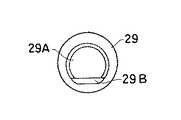
そして、上記の操作部(内視鏡本体)10C側の受け部25に連結して、シャッタ部28が配置される。このシャッタ部28は、逆止弁等として用いられるものと同様の弁29Aを有する弁体29をバネ30で受け部25側へ押圧する構成となっている。即ち、図4に示されるように、この弁体29は例えばゴム製とされ、吸引管17Aの開口を塞ぐ大きさの弁29Aが支点部29Bを軸として、図の前後に倒れるように構成される。
【0016】
また、上記シャッタ部28の奥に、吸引管17Aを保持し、かつ気密保持をするパッキン31を取り付けた支持部32が配置される。一方、上記管路ユニット18側では、吸引管17Bの一部として、上記支持部32のパッキン31まで届く長さの突出管34が設けられており、この突出管34は、上記シャッタ部28の弁29Aを押して倒し管路を開く役目をすることになる。
【0017】
実施形態例は以上の構成からなり、内視鏡を使用する際には、上記操作リング26と受け部25の螺合結合により、上記管路ユニット18が操作部10Cへ接続される。このときに、図2及び図5に示されるように、管路ユニット18側の吸引管17Bの突出管34がシャッタ部28の弁29Aを倒しながらパッキン31の内側まで配置され、吸引管17Aと連結される。従って、シャッタ部28は開状態となって、連結された吸引管17A,17Bを介して、処置具の導入と被観察体内の液体等の吸引、除去が実施される。
【0018】
一方、洗浄等の際に、上記操作部10Cから管路ユニット18を取り外すときは、上記の突出管34がシャッタ部28から抜き出されるので、図1に示されるように、弁19Aが起き上がり、この弁19Aによって吸引管17Aの出口が塞がれる。従って、操作部10C側に汚れた液体等が残っていたとしても、これらの液体を外部へ漏出させることはない。
【0019】
上記実施形態例の図では、吸引管17A,17Bのみを設けた例を説明したが、内視鏡では、送気管或いは送水管等も配置されており、これらの管についても同様に適用することが可能である。
【0020】
また、上記シャッタ部28は本体側の吸引管17Bに設けた例を示したが、上記の構成を逆にして管路ユニット18側へ配置してもよい。更に、このシャッタ部28としては、上記の弁体29以外の構成で、揺動動作、スライド動作により管路を開閉するようなシャッタを用いることができる。
【0021】
【発明の効果】
以上説明したように、本発明によれば、処置具挿通チャンネルの役目もする吸引管が設けられた内視鏡本体に対し管路ユニットを連結部により着脱自在とする内視鏡装置において、上記の連結部における本体側吸引管の開口にパッキンを配置し、上記管路ユニットの吸引管には、本体側吸引管開口のパッキンまで届く長さの連結用突出管を配置すると共に、分岐管を介して処置具導入のための鉗子口を接続し、上記本体側吸引管の開口側に、この開口に対しパッキンを介して接続される連結用突出管を通す状態でこの本体側吸引管の開口を塞ぐためのシャッタ部を配置し、このシャッタ部には、上記管路ユニットの取付け時に連結用突出管で押された弁が支点部を軸として動くことにより開き、取外し時に動いていた弁が戻ることにより閉じる構造のシャッタを設けたので、管路内に残った汚水等が着脱時に垂れて他の管路や器具を汚すことが防止され、清潔な状態を維持できるという利点がある。
【図面の簡単な説明】
【図1】本発明の実施形態例に係る管路を連結する内視鏡装置(連結部)で取外し時の状態を示す断面図である。
【図2】図1の内視鏡装置の連結部の取付け時の状態を示す断面図である。
【図3】図2の内視鏡を操作部の後端側から見た図である。
【図4】実施形態例のシャッタ部の弁体の構成を示す図である。
【図5】図2のシャッタ部の拡大図である。
【符号の説明】
10 … 電子内視鏡、
10C … 操作部(本体側)、
15 … 吸引釦、
17A,17B … 吸引管、
20 … 管路ユニット、
28 … シャッタ部、
29 … 弁体、 29A … 弁、
34 … 突出管。[0001]
BACKGROUND OF THE INVENTION
The present invention relates to an endoscope apparatus that connects pipe lines, particularly an endoscope apparatus that includes at least a suction pipe, and handles the pipe line including the suction pipe so as to be separable from the middle by a pipe line unit. Concerning configuration.
[0002]
[Prior art]
A conventional electronic endoscope (scope), for example, includes a distal end portion having a CCD (Charge Coupled Device), an insertion portion, an operation portion, and a cable, and this cable is connected to a light source device and a processor device. . The endoscope body and cable are provided with a light guide and an electric signal line. Also, an air supply tube and a water supply tube for supplying air / water to the distal end, insertion of a treatment instrument, and contents in the observed body A suction tube or the like for sucking the air is disposed.
[0003]
According to such an endoscope, the light from the light source device is irradiated from the distal end portion through the light guide, and based on this, the object to be observed is imaged and observed by the CCD. Then, air is supplied and water is supplied from the distal end portion to the observation window or the like using the air supply tube and the water supply tube, and the treatment tube can be inserted and dirt and the like in the observed body can be sucked and discharged using the suction tube. Become.
[0004]
[Problems to be solved by the invention]
By the way, since the endoscope apparatus described above is used in a medical field, it is necessary to clean and sterilize the various pipes, and in order to efficiently perform the cleaning and sterilization, the pipes are attached and detached on the way. It has been proposed to separate freely. According to this, the cleaning with the cleaning brush becomes easy, and the separated conduit unit can be sterilized by an autoclave or the like.
[0005]
However, as described above, in the configuration in which the conduit unit is detachable from the endoscope main body side, there is a problem that dirty liquid or the like may sag from the suction tube when the connecting portion is removed. That is, the suction tube guides the treatment tool to the distal end side and sucks liquid remaining in the observed body. If the liquid remaining in the suction tube drips, the other air supply / water supply tubes are soiled. Not only that, the endoscope itself and related equipment will be soiled. Therefore, it is not preferable in terms of hygiene, and extra work increases when cleaning and sterilizing the endoscope including the duct unit.
[0006]
The present invention has been made in view of the above problems, the endoscope and its object is to remaining sewage or the like in thesuction tube is prevented from sagging at the time of detachment, connecting the conduit to maintain a clean condition To provide an apparatus.
[0007]
[Means for Solving the Problems]
In order to achieve the above object, an endoscope apparatus for connecting conduits according to the present invention includes an endoscope main body in whicha suction tube serving as a treatment instrument insertion channel is disposed, and a connecting portion from the main body. detachable be freely, an endoscopic device that includes a channel unit having asuction引管Dothat allow coupling to the body sidesuction tube,packing the opening of the body-side suction pipe at the connecting portion byIn the suction tube of the conduit unit, a connecting protruding tube having a length reaching the packing of the main body side suction tube opening is disposed, and a forceps port for introducing a treatment tool is provided through the branch tube. A shutter portion for closing the opening of the main body side suction pipe is arranged on the opening side of the main body side suction pipe in a state where the connecting projecting pipe connected to the opening through the packing is passed. , the shutter unit, into theendoscope main body side During installation of the pipe unit, openby the pressed in connecting the protruding pipe valve moves the fulcrum portion as an axis, upon removal of the channel unit,the shutter is closed by moving not the valve back structure wherein thesetting digit.
[0008]
According to the above configuration, for example, a shutter can be provided on the endoscope main body side pipe so that a valve (movable plate) of a size that closes the suction pipe falls with the fulcrum portion as an axis. Sometimes the valve is pushed open by a protruding tube on the conduit unit side, and when removed, the valve returns to its original position and closes the conduit. Therefore, the dirty liquid remaining in the suction pipe does not drip when the pipe unit is removed.
[0009]
DETAILED DESCRIPTION OF THE INVENTION
FIGS. 1 to 5 show the configuration of an endoscope apparatus that connects pipes according to the embodiment. First, the configuration of the connecting part between the operation unit and the pipe unit will be described with reference to FIGS. 2 and 3. . In the figure, an electronic endoscope 10 includes a distal end portion (not shown) having a CCD, an insertion portion, an
[0010]
That is, the
[0011]
The
[0012]
A
[0013]
This solenoid valve unit is electrically connected to the processor device, and receives an operation control signal for the
[0014]
As shown in detail in FIG. 1, the connecting
[0015]
Then, the
[0016]
Further, a
[0017]
The embodiment is configured as described above. When the endoscope is used, the
[0018]
On the other hand, when the
[0019]
In the figure of the above embodiment, an example in which only the
[0020]
In addition, although the example in which the
[0021]
【The invention's effect】
As described above, according to the present invention, an endoscope apparatus which detachably by a coupling portion a pipe unit to the endoscope mainbody suction tube which also acts as a treatment instrument insertion channel is provided,the A packing is arranged at the opening of the main body side suction pipe in the connecting portion of the pipe, and a connecting protruding pipe having a length reaching the packing of the main body side suction pipe opening is arranged at the suction pipe of the conduit unit, and a branch pipe is provided. A forceps port for introducing a treatment tool is connected to the opening side of the main body side suction tube, and the connection projecting tube connected to the opening through a packing is passed through the opening side of the main body side suction tube. A shutter that closes the valve is opened, and the valve that was pushed by the connecting protruding pipe when the pipe unit is installed opens by moving around the fulcrum, and the valve that moves when the pipe unit is removed. Close by returning Sincethe shutter structure digitsset, remaining sewage or the like duct is prevented from contaminating the other conduit or instrument dripping during detachment, there is an advantage that can maintain a clean condition.
[Brief description of the drawings]
FIG. 1 is a cross-sectional view showing a state when an endoscope apparatus (connecting portion) connecting pipes according to an embodiment of the present invention is detached.
FIG. 2 is a cross-sectional view showing a state when the connecting portion of the endoscope apparatus of FIG. 1 is attached.
FIG. 3 is a view of the endoscope of FIG. 2 as viewed from the rear end side of an operation unit.
FIG. 4 is a diagram illustrating a configuration of a valve body of a shutter unit according to an exemplary embodiment.
FIG. 5 is an enlarged view of the shutter portion of FIG. 2;
[Explanation of symbols]
10 ... Electronic endoscope,
10C: Operation unit (main body side),
15 ... Suction button,
17A, 17B ... suction tube,
20 ... pipeline unit,
28 ... shutter part,
29 ... Valve body, 29A ... Valve,
34 ... Projection tube.
Claims (1)
Translated fromJapaneseこの本体から連結部により着脱自在とされ、上記本体側吸引管に連結可能となる吸引管を有する管路ユニットとを備えた内視鏡装置であって、
上記連結部における上記本体側吸引管の開口にパッキンを配置し、
上記管路ユニットの吸引管には、上記本体側吸引管開口のパッキンまで届く長さの連結用突出管を配置すると共に、分岐管を介して処置具導入のための鉗子口を接続し、
上記本体側吸引管の開口側に、この開口に対し上記パッキンを介して接続される上記連結用突出管を通す状態でこの本体側吸引管の開口を塞ぐためのシャッタ部を配置し、
このシャッタ部には、上記本体側への上記管路ユニットの取付け時に、上記連結用突出管で押された弁が支点部を軸として動くことにより開き、この管路ユニットの取外し時に、動いていた弁が戻ることにより閉じる構造のシャッタを設けたことを特徴とする管路を連結する内視鏡装置。An endoscope body in whicha suction tube also serving as a treatment instrument insertion channel is disposed;
By this coupling part from the body is detachable, an endoscope apparatus including a channel unit having asuction引管Dothat allow coupling to the body sidesuction tube,
Placing a packing at the opening of the main body side suction pipe in the connecting portion,
The suction pipe of the conduit unit is provided with a connecting projection pipe having a length that reaches the packing of the main body side suction pipe opening, and is connected with a forceps port for introducing a treatment instrument through a branch pipe,
On the opening side of the main body side suction pipe, a shutter part for closing the opening of the main body side suction pipe in a state of passing the connecting projecting pipe connected to the opening through the packing is disposed,
The shutter unit, during installation of the pipe unit to said main body, openby the pressed in connecting the protruding pipe valve moves the fulcrum portion as an axis, upon removal of the channel unit, is moving valve endoscope apparatus for connecting a conduit, wherein the closed digitsset the shutter structure by the back.
Priority Applications (1)
| Application Number | Priority Date | Filing Date | Title |
|---|---|---|---|
| JP08186797AJP3868574B2 (en) | 1997-03-14 | 1997-03-14 | Endoscope device connecting pipes |
Applications Claiming Priority (1)
| Application Number | Priority Date | Filing Date | Title |
|---|---|---|---|
| JP08186797AJP3868574B2 (en) | 1997-03-14 | 1997-03-14 | Endoscope device connecting pipes |
Publications (2)
| Publication Number | Publication Date |
|---|---|
| JPH10248797A JPH10248797A (en) | 1998-09-22 |
| JP3868574B2true JP3868574B2 (en) | 2007-01-17 |
Family
ID=13758430
Family Applications (1)
| Application Number | Title | Priority Date | Filing Date |
|---|---|---|---|
| JP08186797AExpired - Fee RelatedJP3868574B2 (en) | 1997-03-14 | 1997-03-14 | Endoscope device connecting pipes |
Country Status (1)
| Country | Link |
|---|---|
| JP (1) | JP3868574B2 (en) |
Families Citing this family (1)
| Publication number | Priority date | Publication date | Assignee | Title |
|---|---|---|---|---|
| JP5676057B1 (en)* | 2013-07-03 | 2015-02-25 | オリンパスメディカルシステムズ株式会社 | Endoscope connector and endoscope cleaning / disinfecting device |
- 1997
- 1997-03-14JPJP08186797Apatent/JP3868574B2/ennot_activeExpired - Fee Related
Also Published As
| Publication number | Publication date |
|---|---|
| JPH10248797A (en) | 1998-09-22 |
Similar Documents
| Publication | Publication Date | Title |
|---|---|---|
| JPH10225432A (en) | Pipe line separative endoscope device | |
| JP2758435B2 (en) | Endoscope | |
| JP4246469B2 (en) | Endoscope pipe switching device | |
| EP1623664A1 (en) | Endoscope system | |
| JP7114618B2 (en) | Endoscope | |
| JP2000171730A (en) | Battery type portable endoscopic device | |
| JP3621843B2 (en) | Endoscope apparatus having a duct | |
| JP3868574B2 (en) | Endoscope device connecting pipes | |
| JP3649547B2 (en) | Pipe-line separation type endoscopic device | |
| JP3729969B2 (en) | Pipe-line separation type endoscopic device | |
| JP3335561B2 (en) | Endoscope pipeline structure | |
| JP3653158B2 (en) | Endoscope pipe structure | |
| JP3729972B2 (en) | Pipe-line separation type endoscopic device | |
| JP3621799B2 (en) | Endoscopic device for separating pipeline units | |
| JP3655986B2 (en) | Endoscope pipe structure | |
| JP3756621B2 (en) | Endoscope pipe unit connection device | |
| JP3729971B2 (en) | Pipe-line separation type endoscopic device | |
| JP3631349B2 (en) | Pipe unit attachment / detachment device | |
| JP4020321B2 (en) | Pipe-line separation type endoscopic device | |
| JP3621802B2 (en) | Pipe unit connection structure | |
| JP3712820B2 (en) | Endoscope pipe unit connection structure | |
| JP3368616B2 (en) | Endoscope for endoscope cover with channel | |
| JP3760021B2 (en) | Endoscope pipe unit connection device | |
| JP2599952Y2 (en) | Endoscope with endoscope cover method | |
| JPH07116107A (en) | Cover-type endoscope |
Legal Events
| Date | Code | Title | Description |
|---|---|---|---|
| A977 | Report on retrieval | Free format text:JAPANESE INTERMEDIATE CODE: A971007 Effective date:20050913 | |
| A131 | Notification of reasons for refusal | Free format text:JAPANESE INTERMEDIATE CODE: A131 Effective date:20050920 | |
| A521 | Written amendment | Free format text:JAPANESE INTERMEDIATE CODE: A523 Effective date:20051102 | |
| A131 | Notification of reasons for refusal | Free format text:JAPANESE INTERMEDIATE CODE: A131 Effective date:20060704 | |
| A521 | Written amendment | Free format text:JAPANESE INTERMEDIATE CODE: A523 Effective date:20060831 | |
| TRDD | Decision of grant or rejection written | ||
| A01 | Written decision to grant a patent or to grant a registration (utility model) | Free format text:JAPANESE INTERMEDIATE CODE: A01 Effective date:20060926 | |
| A61 | First payment of annual fees (during grant procedure) | Free format text:JAPANESE INTERMEDIATE CODE: A61 Effective date:20061011 | |
| R150 | Certificate of patent or registration of utility model | Free format text:JAPANESE INTERMEDIATE CODE: R150 | |
| FPAY | Renewal fee payment (event date is renewal date of database) | Free format text:PAYMENT UNTIL: 20101020 Year of fee payment:4 | |
| S111 | Request for change of ownership or part of ownership | Free format text:JAPANESE INTERMEDIATE CODE: R313113 | |
| FPAY | Renewal fee payment (event date is renewal date of database) | Free format text:PAYMENT UNTIL: 20101020 Year of fee payment:4 | |
| R350 | Written notification of registration of transfer | Free format text:JAPANESE INTERMEDIATE CODE: R350 | |
| FPAY | Renewal fee payment (event date is renewal date of database) | Free format text:PAYMENT UNTIL: 20111020 Year of fee payment:5 | |
| FPAY | Renewal fee payment (event date is renewal date of database) | Free format text:PAYMENT UNTIL: 20121020 Year of fee payment:6 | |
| FPAY | Renewal fee payment (event date is renewal date of database) | Free format text:PAYMENT UNTIL: 20121020 Year of fee payment:6 | |
| FPAY | Renewal fee payment (event date is renewal date of database) | Free format text:PAYMENT UNTIL: 20131020 Year of fee payment:7 | |
| R250 | Receipt of annual fees | Free format text:JAPANESE INTERMEDIATE CODE: R250 | |
| LAPS | Cancellation because of no payment of annual fees |