JP3868307B2 - Ceramic arc tube assembly and method of forming a ceramic arc tube assembly - Google Patents
Ceramic arc tube assembly and method of forming a ceramic arc tube assemblyDownload PDFInfo
- Publication number
- JP3868307B2 JP3868307B2JP2002043093AJP2002043093AJP3868307B2JP 3868307 B2JP3868307 B2JP 3868307B2JP 2002043093 AJP2002043093 AJP 2002043093AJP 2002043093 AJP2002043093 AJP 2002043093AJP 3868307 B2JP3868307 B2JP 3868307B2
- Authority
- JP
- Japan
- Prior art keywords
- arc tube
- assembly
- button
- ceramic arc
- capillary
- Prior art date
- Legal status (The legal status is an assumption and is not a legal conclusion. Google has not performed a legal analysis and makes no representation as to the accuracy of the status listed.)
- Expired - Fee Related
Links
- 239000000919ceramicSubstances0.000titleclaimsabstractdescription73
- 238000000034methodMethods0.000titleclaimsabstractdescription20
- 238000010438heat treatmentMethods0.000claimsabstractdescription21
- 238000005245sinteringMethods0.000claimsabstractdescription11
- 230000002093peripheral effectEffects0.000claimsdescription11
- 230000003993interactionEffects0.000claimsdescription6
- UFHFLCQGNIYNRP-UHFFFAOYSA-NHydrogenChemical compound[H][H]UFHFLCQGNIYNRP-UHFFFAOYSA-N0.000claimsdescription4
- 229910052739hydrogenInorganic materials0.000claimsdescription4
- 239000001257hydrogenSubstances0.000claimsdescription4
- 238000007789sealingMethods0.000claimsdescription3
- 238000004519manufacturing processMethods0.000abstractdescription8
- 230000001052transient effectEffects0.000abstract1
- CPLXHLVBOLITMK-UHFFFAOYSA-NMagnesium oxideChemical compound[Mg]=OCPLXHLVBOLITMK-UHFFFAOYSA-N0.000description6
- PNEYBMLMFCGWSK-UHFFFAOYSA-Naluminium oxideInorganic materials[O-2].[O-2].[O-2].[Al+3].[Al+3]PNEYBMLMFCGWSK-UHFFFAOYSA-N0.000description3
- 238000003780insertionMethods0.000description3
- 230000037431insertionEffects0.000description3
- 239000000395magnesium oxideSubstances0.000description3
- 230000000149penetrating effectEffects0.000description3
- DGAQECJNVWCQMB-PUAWFVPOSA-MIlexoside XXIXChemical compoundC[C@@H]1CC[C@@]2(CC[C@@]3(C(=CC[C@H]4[C@]3(CC[C@@H]5[C@@]4(CC[C@@H](C5(C)C)OS(=O)(=O)[O-])C)C)[C@@H]2[C@]1(C)O)C)C(=O)O[C@H]6[C@@H]([C@H]([C@@H]([C@H](O6)CO)O)O)O.[Na+]DGAQECJNVWCQMB-PUAWFVPOSA-M0.000description2
- MCMNRKCIXSYSNV-UHFFFAOYSA-NZirconium dioxideChemical compoundO=[Zr]=OMCMNRKCIXSYSNV-UHFFFAOYSA-N0.000description2
- 238000000429assemblyMethods0.000description2
- 230000000712assemblyEffects0.000description2
- 230000008901benefitEffects0.000description2
- 238000001125extrusionMethods0.000description2
- 239000000463materialSubstances0.000description2
- 229910001507metal halideInorganic materials0.000description2
- 150000005309metal halidesChemical class0.000description2
- 239000000843powderSubstances0.000description2
- 238000003825pressingMethods0.000description2
- 229910052708sodiumInorganic materials0.000description2
- 239000011734sodiumSubstances0.000description2
- 238000007796conventional methodMethods0.000description1
- 238000005520cutting processMethods0.000description1
- 238000011161developmentMethods0.000description1
- 238000009792diffusion processMethods0.000description1
- 230000000694effectsEffects0.000description1
- 238000001746injection mouldingMethods0.000description1
- 238000012986modificationMethods0.000description1
- 230000004048modificationEffects0.000description1
- SIWVEOZUMHYXCS-UHFFFAOYSA-Noxo(oxoyttriooxy)yttriumChemical compoundO=[Y]O[Y]=OSIWVEOZUMHYXCS-UHFFFAOYSA-N0.000description1
- 239000007787solidSubstances0.000description1
- 239000000758substrateSubstances0.000description1
Images


Classifications
- C—CHEMISTRY; METALLURGY
- C04—CEMENTS; CONCRETE; ARTIFICIAL STONE; CERAMICS; REFRACTORIES
- C04B—LIME, MAGNESIA; SLAG; CEMENTS; COMPOSITIONS THEREOF, e.g. MORTARS, CONCRETE OR LIKE BUILDING MATERIALS; ARTIFICIAL STONE; CERAMICS; REFRACTORIES; TREATMENT OF NATURAL STONE
- C04B37/00—Joining burned ceramic articles with other burned ceramic articles or other articles by heating
- C04B37/001—Joining burned ceramic articles with other burned ceramic articles or other articles by heating directly with other burned ceramic articles
- H—ELECTRICITY
- H01—ELECTRIC ELEMENTS
- H01J—ELECTRIC DISCHARGE TUBES OR DISCHARGE LAMPS
- H01J61/00—Gas-discharge or vapour-discharge lamps
- H01J61/02—Details
- H01J61/30—Vessels; Containers
- H—ELECTRICITY
- H01—ELECTRIC ELEMENTS
- H01J—ELECTRIC DISCHARGE TUBES OR DISCHARGE LAMPS
- H01J61/00—Gas-discharge or vapour-discharge lamps
- H01J61/82—Lamps with high-pressure unconstricted discharge having a cold pressure > 400 Torr
- H01J61/825—High-pressure sodium lamps
- H—ELECTRICITY
- H01—ELECTRIC ELEMENTS
- H01J—ELECTRIC DISCHARGE TUBES OR DISCHARGE LAMPS
- H01J9/00—Apparatus or processes specially adapted for the manufacture, installation, removal, maintenance of electric discharge tubes, discharge lamps, or parts thereof; Recovery of material from discharge tubes or lamps
- H01J9/24—Manufacture or joining of vessels, leading-in conductors or bases
- H01J9/245—Manufacture or joining of vessels, leading-in conductors or bases specially adapted for gas discharge tubes or lamps
- H01J9/247—Manufacture or joining of vessels, leading-in conductors or bases specially adapted for gas discharge tubes or lamps specially adapted for gas-discharge lamps
- H—ELECTRICITY
- H01—ELECTRIC ELEMENTS
- H01J—ELECTRIC DISCHARGE TUBES OR DISCHARGE LAMPS
- H01J9/00—Apparatus or processes specially adapted for the manufacture, installation, removal, maintenance of electric discharge tubes, discharge lamps, or parts thereof; Recovery of material from discharge tubes or lamps
- H01J9/24—Manufacture or joining of vessels, leading-in conductors or bases
- H01J9/26—Sealing together parts of vessels
- H01J9/265—Sealing together parts of vessels specially adapted for gas-discharge tubes or lamps
- H01J9/266—Sealing together parts of vessels specially adapted for gas-discharge tubes or lamps specially adapted for gas-discharge lamps
- C—CHEMISTRY; METALLURGY
- C04—CEMENTS; CONCRETE; ARTIFICIAL STONE; CERAMICS; REFRACTORIES
- C04B—LIME, MAGNESIA; SLAG; CEMENTS; COMPOSITIONS THEREOF, e.g. MORTARS, CONCRETE OR LIKE BUILDING MATERIALS; ARTIFICIAL STONE; CERAMICS; REFRACTORIES; TREATMENT OF NATURAL STONE
- C04B2235/00—Aspects relating to ceramic starting mixtures or sintered ceramic products
- C04B2235/65—Aspects relating to heat treatments of ceramic bodies such as green ceramics or pre-sintered ceramics, e.g. burning, sintering or melting processes
- C04B2235/656—Aspects relating to heat treatments of ceramic bodies such as green ceramics or pre-sintered ceramics, e.g. burning, sintering or melting processes characterised by specific heating conditions during heat treatment
- C04B2235/6567—Treatment time
- C—CHEMISTRY; METALLURGY
- C04—CEMENTS; CONCRETE; ARTIFICIAL STONE; CERAMICS; REFRACTORIES
- C04B—LIME, MAGNESIA; SLAG; CEMENTS; COMPOSITIONS THEREOF, e.g. MORTARS, CONCRETE OR LIKE BUILDING MATERIALS; ARTIFICIAL STONE; CERAMICS; REFRACTORIES; TREATMENT OF NATURAL STONE
- C04B2235/00—Aspects relating to ceramic starting mixtures or sintered ceramic products
- C04B2235/65—Aspects relating to heat treatments of ceramic bodies such as green ceramics or pre-sintered ceramics, e.g. burning, sintering or melting processes
- C04B2235/658—Atmosphere during thermal treatment
- C04B2235/6582—Hydrogen containing atmosphere
- C—CHEMISTRY; METALLURGY
- C04—CEMENTS; CONCRETE; ARTIFICIAL STONE; CERAMICS; REFRACTORIES
- C04B—LIME, MAGNESIA; SLAG; CEMENTS; COMPOSITIONS THEREOF, e.g. MORTARS, CONCRETE OR LIKE BUILDING MATERIALS; ARTIFICIAL STONE; CERAMICS; REFRACTORIES; TREATMENT OF NATURAL STONE
- C04B2237/00—Aspects relating to ceramic laminates or to joining of ceramic articles with other articles by heating
- C04B2237/30—Composition of layers of ceramic laminates or of ceramic or metallic articles to be joined by heating, e.g. Si substrates
- C04B2237/32—Ceramic
- C04B2237/34—Oxidic
- C04B2237/343—Alumina or aluminates
- C—CHEMISTRY; METALLURGY
- C04—CEMENTS; CONCRETE; ARTIFICIAL STONE; CERAMICS; REFRACTORIES
- C04B—LIME, MAGNESIA; SLAG; CEMENTS; COMPOSITIONS THEREOF, e.g. MORTARS, CONCRETE OR LIKE BUILDING MATERIALS; ARTIFICIAL STONE; CERAMICS; REFRACTORIES; TREATMENT OF NATURAL STONE
- C04B2237/00—Aspects relating to ceramic laminates or to joining of ceramic articles with other articles by heating
- C04B2237/50—Processing aspects relating to ceramic laminates or to the joining of ceramic articles with other articles by heating
- C04B2237/52—Pre-treatment of the joining surfaces, e.g. cleaning, machining
- C04B2237/525—Pre-treatment of the joining surfaces, e.g. cleaning, machining by heating
- C—CHEMISTRY; METALLURGY
- C04—CEMENTS; CONCRETE; ARTIFICIAL STONE; CERAMICS; REFRACTORIES
- C04B—LIME, MAGNESIA; SLAG; CEMENTS; COMPOSITIONS THEREOF, e.g. MORTARS, CONCRETE OR LIKE BUILDING MATERIALS; ARTIFICIAL STONE; CERAMICS; REFRACTORIES; TREATMENT OF NATURAL STONE
- C04B2237/00—Aspects relating to ceramic laminates or to joining of ceramic articles with other articles by heating
- C04B2237/50—Processing aspects relating to ceramic laminates or to the joining of ceramic articles with other articles by heating
- C04B2237/56—Using constraining layers before or during sintering
- C—CHEMISTRY; METALLURGY
- C04—CEMENTS; CONCRETE; ARTIFICIAL STONE; CERAMICS; REFRACTORIES
- C04B—LIME, MAGNESIA; SLAG; CEMENTS; COMPOSITIONS THEREOF, e.g. MORTARS, CONCRETE OR LIKE BUILDING MATERIALS; ARTIFICIAL STONE; CERAMICS; REFRACTORIES; TREATMENT OF NATURAL STONE
- C04B2237/00—Aspects relating to ceramic laminates or to joining of ceramic articles with other articles by heating
- C04B2237/50—Processing aspects relating to ceramic laminates or to the joining of ceramic articles with other articles by heating
- C04B2237/62—Forming laminates or joined articles comprising holes, channels or other types of openings
- C—CHEMISTRY; METALLURGY
- C04—CEMENTS; CONCRETE; ARTIFICIAL STONE; CERAMICS; REFRACTORIES
- C04B—LIME, MAGNESIA; SLAG; CEMENTS; COMPOSITIONS THEREOF, e.g. MORTARS, CONCRETE OR LIKE BUILDING MATERIALS; ARTIFICIAL STONE; CERAMICS; REFRACTORIES; TREATMENT OF NATURAL STONE
- C04B2237/00—Aspects relating to ceramic laminates or to joining of ceramic articles with other articles by heating
- C04B2237/50—Processing aspects relating to ceramic laminates or to the joining of ceramic articles with other articles by heating
- C04B2237/76—Forming laminates or joined articles comprising at least one member in the form other than a sheet or disc, e.g. two tubes or a tube and a sheet or disc
- C04B2237/765—Forming laminates or joined articles comprising at least one member in the form other than a sheet or disc, e.g. two tubes or a tube and a sheet or disc at least one member being a tube
- C—CHEMISTRY; METALLURGY
- C04—CEMENTS; CONCRETE; ARTIFICIAL STONE; CERAMICS; REFRACTORIES
- C04B—LIME, MAGNESIA; SLAG; CEMENTS; COMPOSITIONS THEREOF, e.g. MORTARS, CONCRETE OR LIKE BUILDING MATERIALS; ARTIFICIAL STONE; CERAMICS; REFRACTORIES; TREATMENT OF NATURAL STONE
- C04B2237/00—Aspects relating to ceramic laminates or to joining of ceramic articles with other articles by heating
- C04B2237/50—Processing aspects relating to ceramic laminates or to the joining of ceramic articles with other articles by heating
- C04B2237/80—Joining the largest surface of one substrate with a smaller surface of the other substrate, e.g. butt joining or forming a T-joint
- C—CHEMISTRY; METALLURGY
- C04—CEMENTS; CONCRETE; ARTIFICIAL STONE; CERAMICS; REFRACTORIES
- C04B—LIME, MAGNESIA; SLAG; CEMENTS; COMPOSITIONS THEREOF, e.g. MORTARS, CONCRETE OR LIKE BUILDING MATERIALS; ARTIFICIAL STONE; CERAMICS; REFRACTORIES; TREATMENT OF NATURAL STONE
- C04B2237/00—Aspects relating to ceramic laminates or to joining of ceramic articles with other articles by heating
- C04B2237/50—Processing aspects relating to ceramic laminates or to the joining of ceramic articles with other articles by heating
- C04B2237/82—Two substrates not completely covering each other, e.g. two plates in a staggered position
- C—CHEMISTRY; METALLURGY
- C04—CEMENTS; CONCRETE; ARTIFICIAL STONE; CERAMICS; REFRACTORIES
- C04B—LIME, MAGNESIA; SLAG; CEMENTS; COMPOSITIONS THEREOF, e.g. MORTARS, CONCRETE OR LIKE BUILDING MATERIALS; ARTIFICIAL STONE; CERAMICS; REFRACTORIES; TREATMENT OF NATURAL STONE
- C04B2237/00—Aspects relating to ceramic laminates or to joining of ceramic articles with other articles by heating
- C04B2237/50—Processing aspects relating to ceramic laminates or to the joining of ceramic articles with other articles by heating
- C04B2237/84—Joining of a first substrate with a second substrate at least partially inside the first substrate, where the bonding area is at the inside of the first substrate, e.g. one tube inside another tube
Landscapes
- Engineering & Computer Science (AREA)
- Chemical & Material Sciences (AREA)
- Manufacturing & Machinery (AREA)
- Ceramic Engineering (AREA)
- Organic Chemistry (AREA)
- Structural Engineering (AREA)
- Materials Engineering (AREA)
- Vessels And Coating Films For Discharge Lamps (AREA)
- Ceramic Products (AREA)
- Manufacture Of Electron Tubes, Discharge Lamp Vessels, Lead-In Wires, And The Like (AREA)
- Rigid Pipes And Flexible Pipes (AREA)
- Microwave Tubes (AREA)
- Nonmetallic Welding Materials (AREA)
Abstract
Description
Translated fromJapanese【0001】
【発明の属する技術分野】
本出願は、2001年2月23日に出願された米国仮出願第60/271153号の利益を主張する。
【0002】
本発明は、セラミック発光管、特にセラミック発光管アセンブリおよびこのようなアセンブリを形成する方法に関する。
【0003】
【従来の技術】
長年に亘り、多結晶アルミナ等の材料から構成されるセラミック発光管が、高圧ナトリウムランプの放電を収容しているために使用されている。セラミック発光管は、ナトリウムランプにおいて使用するための多数の発光管構成の発展をもたらしている。例えば、米国特許第4766347号明細書は、3片発光管構成を説明しており、この構成では、発光管が管状の閉鎖部材を備えたセラミックボディから構成されている。電極を収容する閉鎖部材は、セラミックボディの端部に直接シールされている。別の実施例において、米国特許第5426343号明細書は、端部シールボタンが使用された3片発光管構成を説明しており、これらの端部シールボタンは、端部シールボタンと一体的な延長した電極収容部材を有している。
【0004】
近年では、セラミック発光管が、メタルハライドランプにおいて使用されている。例えば、米国特許第5424609号明細書は、メタルハライドランプのための5片セラミック発光管構成を説明している。5片発光管は、円筒状のボディと、1対の端部シールボタンと、これらの端部シールボタンにシールされた1対の毛管とを含んでいる。これらのセラミック発光管の製造は、個々のコンポーネントの押出し成形または加圧成形、また多くの組立ておよび熱処理ステップを必要とする。これらの多くのステップは、製造コストを増大させる取扱いの増加をもたらす。
【0005】
【発明が解決しようとする課題】
したがって、本発明の課題は、従来技術の欠点を取り除くことである。
【0006】
本発明の別の課題は、セラミック発光管の製造を容易にしかつ単純化するセラミック発光管アセンブリを提供することである。
【0007】
本発明の別の課題は、製造プロセスにおける取扱いおよび加熱ステップの回数を低減する、セラミック発光管を形成する方法を提供することである。
【0008】
【課題を解決するための手段】
本発明の1つの課題に従って、端部キャップを収容した少なくとも1つの開放端部を有する中空ボディが設けられており、端部キャップが、毛管と、一時的なアセンブリボタンとを有しており、毛管が、中空ボディから外方に延びておりかつ開放端部に挿入される長さを有しておりかつ中空ボディとシールを形成し、一時的なアセンブリボタンが、毛管の周囲に固定されておりかつ開放端部の縁部と接触しており、一時的なアセンブリボタンと開放端部の縁部との相互作用が、開放端部に挿入される毛管の長さを決定し、さらに、一時的なアセンブリボタンを、発光管アセンブリに損傷を与えることなしに毛管から取り外すことができるようになっているセラミック発光管アセンブリが提供される。
【0009】
本発明の別の課題に従って、(a)端部キャップを形成するために一時的なアセンブリボタンを毛管の周囲に固定し、(b)一時的なアセンブリボタンが開放端部の縁部と接触するまで端部キャップを中空発光管ボディの開放端部に挿入し、(c)毛管と中空ボディの開放端部との間に機械的なシールを形成するためにアセンブリを加熱し、(d)アセンブリに損傷を与えることなしに一時的なアセンブリボタンを取り外し、(e)セラミック発光管を形成するためにアセンブリを焼結するステップを含むセラミック発光管を形成する方法が提供される。
【0010】
【発明の実施の形態】
本発明の他の課題、利点および能力と共に本発明をより良く理解するために、後で説明する図面と共に理解される以下の開示および添付の請求項が参照される。
【0011】
本発明のセラミック発光管アセンブリおよび方法は、最終的な焼結作業の前に発光管を組み立てるために必要とされる取扱いおよび熱処理の回数を低減することによって、セラミック発光管の製造を単純化する。1つの実施例において、セラミック発光管アセンブリは、端部キャップを収容している少なくとも1つの開放端部を有する中空の発光管ボディから構成されている。端部キャップは、一時的なアセンブリボタンと、電極を収容するための毛管とから構成されている。一時的なアセンブリボタンは最初の熱処理によって毛管の周囲に固着され、この熱処理はこの一時的なアセンブリボタンを収縮させかつ圧縮させて毛管に対して締め付ける。コンポーネントが組み立てられている時に、一時的なアセンブリボタンは、開放端部の縁部と相互作用し、端部キャップが発光管ボディに奥深く突入するのを制限する。この相互作用が、発光管ボディ内へ挿入される毛管の長さを決定する。コンポーネントが組み立てられた後に、次いで、端部キャップは第2の熱処理ステップにおいて発光管ボディに結合され、この第2の熱処理ステップは端部キャップを発光管ボディに機械的にシールさせる。次いで、完成された発光管が、一時的なアセンブリボタンを取外ししかつ、最終的な焼結作業において、組み立てられた発光管を加熱することによって形成される。
【0012】
別の実施例において、毛管は半径方向に延びたシール部材を有しており、このシール部材は発光管ボディの開放端部内に挿入されかつ開放端部内にシールされる。シール部材は、最初の熱処理において一時的なアセンブリボタンと共に毛管に結合される別個の部材から構成されてもよく、毛管の一体的な部分として形成されてもよい。有利には、一時的なアセンブリボタンは、環状のディスク形状を有しており、この場合、毛管は中央開口に挿入される。しかしながら、発光管アセンブリに損傷を与えることなく最終的な焼結作業の前に一時的なアセンブリボタンを取外しすることができるならば、その他の形状も同様に有効である。
【0013】
発光管の両端部が、発光管内にシールしたい端部キャップを必要とする場合には、一時的なアセンブリボタンの使用は特に有利である。なぜならば、一時的なアセンブリボタンにより、発光管アセンブリの両端部を垂直な向きで同時にシールすることができるからである。一時的なアセンブリボタンは、2つの異なる温度での2つの連続した熱処理においてボディ部分の各端部を端部キャップにシールする必要性を除外することによって、組立てプロセスを単純化する。
【0014】
有利には、本発明のセラミック発光管アセンブリは、少量のマグネシアを含んだ多結晶アルミナ、別の例においては酸化イットリウムおよびジルコニアから形成されている。このような材料は、米国特許第5682082号明細書に示されている。この分野において知られているように、その他の少量成分が含まれていてもよい。有利な実施例において、発光管アセンブリ(毛管、一時的なアセンブリボタン、シール部材)の端部キャップは、0.05質量%のマグネシアを含んだバイコウスキー社製グレードCR−6のアルミナ粉末から形成されており、ボディ部分は、0.05質量%のマグネシアを含んだ、バイコウスキー社製グレードCR−6またはバイコウスキー社製グレードCR−30粉末のうちの一方から形成されている。セラミック発光管アセンブリのコンポーネントは、多数の慣用の方法、例えば、押出し成形、加圧成形または射出成形によって形成されてよい。
【0015】
発光管アセンブリにおけるコンポーネントの相対位置は、約1350℃以下の熱処理ステップにおいて固定される。熱処理は、コンポーネントを高密度化しかつ収縮させ、コンポーネントの位置を固定する圧縮力を生ぜしめる。比較的低温の熱処理ステップのために、コンポーネントを化学的に結合するためのコンポーネント間の交差拡散(cross diffusion)または結晶粒成長は生じない。さらに、1350℃以下の温度において、一時的なアセンブリボタンは、これらの一時的なアセンブリボタンの強度を制限する著しい多孔性を保持している。これにより、発光管アセンブリに損傷を与えることなしに、一時的なアセンブリボタンを毛管から簡単に取り外すことができる。
【0016】
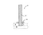
図1から図3は、ここに説明されている本発明を使用した3片セラミック発光管のための製造の様々な段階を示している。図1においては、毛管2と一時的なアセンブリボタン11とから構成される端部キャップ3は、毛管2を、調節された厚さLの穿孔されたセラミックプレート5(点線で示されている)に設けられた孔に貫通させることによって形成される。穿孔されたセラミックプレート5は、中実のセラミックプレート10(やはり点線で示されている)上に載置されており、毛管2が穿孔されたプレート5を完全に貫通するのを妨止する。一時的なアセンブリボタン11は、毛管2上に配置されかつ穿孔されたセラミックプレート5によって支持される。次いで、プレートおよび支持された端部キャップコンポーネントは、炉内に配置されかつ約1200℃〜約1250℃の空気中で加熱される。この最初の熱処理は、一時的なアセンブリボタン11を収縮させかつ毛管2の周囲に固定させる。穿孔されたセラミックプレート5の厚さLは、発光管ボディ内に挿入される毛管2の長さに相当する。
【0017】
図2において、発光管アセンブリは、端部キャップ3aの毛管2aを、穿孔されたセラミックプレート5(点線で示されている)に設けられた孔に貫通させることによって形成されており、毛管2aの突出した端部は、プレート5およびプレート上に支持された一時的なアセンブリボタン11aの下方に延びている。開放端部7a,7bを有した中空の楕円形のボディ部分4は、端部キャップ3aの毛管部分上に配置される。第2の端部キャップ3bは、中空体の反対側の端部7bに挿入される。各端部キャップ3a,3bの一時的なアセンブリボタン11a,11bの周縁部17a,17bは、組立ての直前には、開放端部7a,7bの内径よりも大きくなければならない。中空体の開放端部7a,7bに挿入される毛管2a,2bの長さは、開放端部7a,7bの縁部13a,13bと一時的なアセンブリボタン11a,11bとの相互作用によって決定される。組立て後、一時的なアセンブリボタン11a,11bの周縁部17a,17bは、一時的なアセンブリボタン11a,11bの取外しを容易にするために開放端部7a,7bの周縁部19a,19bよりも大きいことが好ましい。一時的なアセンブリボタン11a,11bが、開放端部の周縁部を越えて約1mmだけ延びていると有利である。次いで、組み立てられたコンポーネントは、約1250℃〜約1350℃の空気中で熱処理され、この熱処理中、ボディ部分は十分に高密度化し、収縮して毛管に対して締め付けられ、機械的なシール9a,9bおよび完成された発光管アセンブリを形成する。
【0018】
次いで、一時的なアセンブリボタンが、発光管アセンブリに損傷を与えることなく毛管2から取り外される。発光管アセンブリは、水素を含んだ雰囲気中での約1800℃以上の温度の最終的な焼結作業において、水平方向でまたは、有利な方法においては、垂直方向で加熱されてよい。有利には、最終的な焼結は、100%水素中で約180分間、約1880℃の温度で行われる。完成された発光管が図3に示されている。最終的な焼結作業は、さらなる収縮と相俟って、発光管アセンブリ内の既存の機械的なシールにおける結晶粒成長および相互拡散を促進させる。これらの作用は、焼結されたアセンブリにおいて、真空かつ気密であるハーメチックシールを形成する。
【0019】
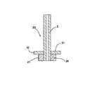
図4から図6は、ここに説明される本発明を使用した5片セラミック発光管のための製造の様々な段階を示している。図4において、毛管2と、シール部材25と、一時的なアセンブリボタン11とから構成される端部キャップ23が示されている。一時的なアセンブリボタン11の周縁部17は、シール部材25の周縁部21を越えて延びている。端部キャップコンポーネントは、セラミックプレート(図示せず)上に組み付けられかつ約1200℃〜約1250℃の空気中で熱処理される。この熱処理中、シール部材25および一時的なアセンブリボタン11は、十分に高密度化し、収縮して毛管2に締め付けられ、コンポーネントの相対位置を固定する圧縮力を与える。
【0020】
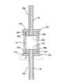
図5に示されている発光管アセンブリは、端部キャップ23aの毛管2aを、穿孔されたセラミックプレート5(点線で示されている)に設けられた孔に貫通させることによって形成され、この場合、毛管2aの突出した端部は、プレート5およびプレート上に支持された一時的なアセンブリボタン11aの下方に延びている。向かい合った開放端部27a,27bを有する円筒状の中空発光管ボディ若しくは中空ボディ24が、端部キャップ23aのシール部材25a上に配置される。
【0021】
第2の端部キャップ23bが、円筒状のボディ部分の反対側の開放端部27b内に挿入される。一時的なアセンブリボタン11a,11bの周縁部17a,17bは、組立ての直前には、円筒状ボディの開放端部27a,27bの内径よりも大きくなければならない。一時的なアセンブリボタン11a,11bと開放端部27a,27bの縁部33a,33bとの間の相互作用が、毛管2a,2bの挿入長さを決定する。組立て後、一時的なアセンブリボタン11a,11bの周縁部17a,17bは、一時的なアセンブリボタンの取外しを容易にするために、開放端部27a,27bの外径を越えて延びていることが好ましい。
【0022】
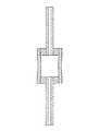
次いで、発光管アセンブリは、約1250℃〜約1350℃の空気中で熱処理され、これにより円筒状のボディを収縮させシール部材25a,25bに対して締め付け、機械的なシール29a,29bを形成する。次いで、一時的なアセンブリボタンが毛管から取り外され、アセンブリに最終的な焼結が行われ、図6に示したような完成された発光管を形成する。
【0023】
本発明の5片発光管アセンブリの別の実施例が図7に示されており、この5片発光管アセンブリは、底部の端部キャップ23aが一時的なシールボタン若しくは一時的なアセンブリボタンを用いて形成されていないことを除いて、図5に示した発光管アセンブリと同様である。一時的なアセンブリボタン11を利用する端部キャップ23bが、中空ボディ24の上部開放端部27bにのみ挿入される。毛管2bの挿入長さは、一時的なアセンブリボタン11と縁部33bとの相互作用によって決定されるのに対して、毛管2aの挿入長さは、穿孔されたプレート5(点線で示されている)の面と縁部33aとの相互作用によって決定される。開放端部27a,27b内にシール部材25a,25bを機械的シールするための熱処理後に、唯一の一時的なアセンブリボタンが上部毛管2bから取り外され完成したアセンブリを形成する。
【0024】
別の実施例において、毛管2には、一時的なアセンブリボタン11またはシール部材25に結合される前に、予備熱処理が提供されてよい。予備熱処理は、毛管を高密度化し、毛管を収縮させ、これにより、毛管は一時的なアセンブリボタンまたはシール部材内の開口に嵌め込まれる。前処理は、約1250℃〜約1350℃の温度の空気中で行われてよい。
【0025】
一時的なアセンブリボタンの取外しを一層容易にするために、一時的なアセンブリボタンの強度をさらに減じるようにボタンに溝または切欠きを設けることがしばしば望ましい。一時的なアセンブリボタンに設けられる溝は、通常、一方の側に、ボタンの厚さの約50%〜約75%の深さで形成される。溝は、ボタン型成形工具に設けられた形状的特徴または研磨鋸による切断によって形成することができる。溝を備えた環状のディスクから成る一時的なアセンブリボタンが図8に示されている。溝58は、ボタン51の直径に沿って切断されている。溝が設けられた一時的なアセンブリボタンを使用する場合、端部キャップの組付け時に、端部キャップが挿入される時に溝が発光管ボディの開放端部に面するように向けられることが好ましい。この向きにより、溝は、取外し時に最大の引張り応力を受けることができる。
【0026】
一時的なアセンブリボタンの強度を減じるための第2の方法は、ボタンに切欠きを設けることである。図9に示されている有利な実施例において、切欠き68は、ボタン61を途中まで貫いて延びている。この場合、端部キャップ上での一時的なアセンブリボタンの向きは重要ではない。
【0027】
より厚い一時的なアセンブリボタンに対しては、溝および切欠きを、取外しの容易さを向上させるために様々に組み合せて利用することができる。
【0028】
現時点で本発明の有利な実施例であると考えられるものが示されかつ説明されているが、添付の請求項によって規定されるような本発明の範囲から逸脱することなしに、実施例において様々な変更および修正がなされてよいことは、当業者にとって明らかである。
【図面の簡単な説明】
【図1】3片セラミック発光管アセンブリのための端部キャップを示す縦断面図である。
【図2】3片セラミック発光管アセンブリを示す縦断面図である。
【図3】完成されたセラミック3片発光管を示す縦断面図である。
【図4】5片セラミック発光管アセンブリのための端部キャップを示す縦断面図である。
【図5】5片セラミック発光管アセンブリを示す縦断面図である。
【図6】完成されたセラミック5片発光管を示す縦断面図である。
【図7】5片セラミック発光管アセンブリの別の実施例を示す縦断面図である。
【図8】溝が設けられた一時的なアセンブリボタンを示す図である。
【図9】切欠きが設けられた一時的なアセンブリボタンを示す図である。
【符号の説明】
2,2a,2b 毛管、 3,3a,3b 端部キャップ、 4 中空の楕円形ボディ部分、 5,10 セラミックプレート、 7a,7b 開放端部、 9a,9b,9a′,9b′ シール、 11,11a,11b 一時的なアセンブリボタン、 13a,13b 縁部、 17,17a,17b,19a,19b,21 周縁部、 23,23a,23b 端部キャップ、 24 管ボディ、 25,25a,25b シール部材、 27a,27b 開放端部、 29a,29b シール、 33a,33b 縁部、 51 ボタン、 58 溝、 68 切欠き[0001]
BACKGROUND OF THE INVENTION
This application claims the benefit of US Provisional Application No. 60/271153, filed Feb. 23, 2001.
[0002]
The present invention relates to ceramic arc tubes, particularly ceramic arc tube assemblies, and methods of forming such assemblies.
[0003]
[Prior art]
For many years, ceramic arc tubes composed of materials such as polycrystalline alumina have been used to accommodate the discharge of high pressure sodium lamps. Ceramic arc tubes have led to the development of numerous arc tube configurations for use in sodium lamps. For example, U.S. Pat. No. 4,766,347 describes a three-piece arc tube configuration, in which the arc tube is composed of a ceramic body with a tubular closure member. The closure member that houses the electrode is directly sealed to the end of the ceramic body. In another embodiment, U.S. Pat. No. 5,426,343 describes a three piece arc tube configuration in which end seal buttons are used, which end seal buttons are integral with the end seal button. It has an extended electrode housing member.
[0004]
In recent years, ceramic arc tubes have been used in metal halide lamps. For example, US Pat. No. 5,424,609 describes a five piece ceramic arc tube configuration for a metal halide lamp. The five-piece arc tube includes a cylindrical body, a pair of end seal buttons, and a pair of capillaries sealed to the end seal buttons. The manufacture of these ceramic arc tubes requires extrusion or pressing of individual components and a number of assembly and heat treatment steps. Many of these steps result in increased handling that increases manufacturing costs.
[0005]
[Problems to be solved by the invention]
The object of the present invention is therefore to eliminate the disadvantages of the prior art.
[0006]
Another object of the present invention is to provide a ceramic arc tube assembly that facilitates and simplifies the manufacture of ceramic arc tubes.
[0007]
Another object of the present invention is to provide a method of forming a ceramic arc tube that reduces the number of handling and heating steps in the manufacturing process.
[0008]
[Means for Solving the Problems]
In accordance with one subject of the present invention, a hollow body having at least one open end that houses an end cap is provided, the end cap having a capillary and a temporary assembly button; A capillary extends outward from the hollow body and has a length that is inserted into the open end and forms a seal with the hollow body, and a temporary assembly button is secured around the capillary And the interaction between the temporary assembly button and the edge of the open end determines the length of the capillary inserted into the open end, and A ceramic arc tube assembly is provided that allows a typical assembly button to be removed from the capillary without damaging the arc tube assembly.
[0009]
In accordance with another subject of the present invention, (a) a temporary assembly button is secured around the capillary to form an end cap, and (b) the temporary assembly button contacts the edge of the open end. Insert the end cap into the open end of the hollow arc tube body until (c) heat the assembly to form a mechanical seal between the capillary and the open end of the hollow body; (d) the assembly A method is provided for forming a ceramic arc tube comprising removing a temporary assembly button without damaging the substrate and (e) sintering the assembly to form a ceramic arc tube.
[0010]
DETAILED DESCRIPTION OF THE INVENTION
For a better understanding of the present invention, together with other objects, advantages and capabilities of the present invention, reference is made to the following disclosure and appended claims which are understood in conjunction with the drawings described below.
[0011]
The ceramic arc tube assembly and method of the present invention simplifies the manufacture of ceramic arc tubes by reducing the number of handling and heat treatments required to assemble the arc tube prior to the final sintering operation. . In one embodiment, the ceramic arc tube assembly is comprised of a hollow arc tube body having at least one open end that houses an end cap. The end cap consists of a temporary assembly button and a capillary for receiving the electrode. The temporary assembly button is secured around the capillary by an initial heat treatment that causes the temporary assembly button to contract and compress to clamp against the capillary. When the component is being assembled, the temporary assembly button interacts with the edge of the open end, limiting the end cap from penetrating deeply into the arc tube body. This interaction determines the length of the capillary that is inserted into the arc tube body. After the components are assembled, the end cap is then bonded to the arc tube body in a second heat treatment step, which mechanically seals the end cap to the arc tube body. The completed arc tube is then formed by removing the temporary assembly button and heating the assembled arc tube in the final sintering operation.
[0012]
In another embodiment, the capillary tube has a radially extending seal member that is inserted into and sealed within the open end of the arc tube body. The seal member may be composed of a separate member that is coupled to the capillary with the temporary assembly button in the initial heat treatment, or may be formed as an integral part of the capillary. Advantageously, the temporary assembly button has an annular disc shape, in which case the capillary is inserted into the central opening. However, other shapes are equally useful if the temporary assembly button can be removed prior to the final sintering operation without damaging the arc tube assembly.
[0013]
The use of temporary assembly buttons is particularly advantageous when both ends of the arc tube require end caps that are desired to be sealed within the arc tube. This is because both ends of the arc tube assembly can be simultaneously sealed in a vertical orientation by a temporary assembly button. The temporary assembly button simplifies the assembly process by eliminating the need to seal each end of the body part to the end cap in two successive heat treatments at two different temperatures.
[0014]
Advantageously, the ceramic arc tube assembly of the present invention is formed from polycrystalline alumina containing a small amount of magnesia, in another example yttrium oxide and zirconia. Such a material is shown in US Pat. No. 5,682,082. Other minor components may be included as is known in the art. In an advantageous embodiment, the end cap of the arc tube assembly (capillary, temporary assembly button, seal member) is made from a Baikosky grade CR-6 alumina powder containing 0.05 wt% magnesia. The body part is formed from one of Baikowski grade CR-6 or Baikowski grade CR-30 powder containing 0.05 wt% magnesia. The components of the ceramic arc tube assembly may be formed by a number of conventional methods, such as extrusion, pressing or injection molding.
[0015]
The relative position of the components in the arc tube assembly is fixed in a heat treatment step of about 1350 ° C. or less. The heat treatment creates a compressive force that densifies and shrinks the component and fixes the position of the component. Due to the relatively low temperature heat treatment step, no cross diffusion or grain growth between the components to chemically bond the components occurs. Further, at temperatures below 1350 ° C., temporary assembly buttons retain significant porosity that limits the strength of these temporary assembly buttons. This allows the temporary assembly button to be easily removed from the capillary tube without damaging the arc tube assembly.
[0016]
FIGS. 1-3 illustrate various stages of manufacture for a three piece ceramic arc tube using the invention described herein. In FIG. 1, an end cap 3 consisting of a
[0017]
In FIG. 2, the arc tube assembly is formed by passing the capillary 2a of the
[0018]
The temporary assembly button is then removed from the
[0019]
4-6 illustrate various stages of manufacture for a five piece ceramic arc tube using the invention described herein. In FIG. 4, an
[0020]
The arc tube assembly shown in FIG. 5 is formed by passing the capillary 2a of the
[0021]
A
[0022]
The arc tube assembly is then heat treated in air at about 1250 ° C. to about 1350 ° C., thereby shrinking the cylindrical body and tightening against the
[0023]
Another embodiment of a five piece arc tube assembly of the present invention is shown in FIG. 7, which uses a temporary seal button or a temporary assembly button at the
[0024]
In another embodiment, the
[0025]
In order to make it easier to remove the temporary assembly button, it is often desirable to provide the button with a groove or notch to further reduce the strength of the temporary assembly button. Grooves provided in temporary assembly buttons are typically formed on one side to a depth of about 50% to about 75% of the button thickness. The grooves can be formed by geometric features provided on the button mold tool or by cutting with an abrasive saw. A temporary assembly button consisting of an annular disc with a groove is shown in FIG. The
[0026]
A second way to reduce the strength of the temporary assembly button is to provide a notch in the button. In the advantageous embodiment shown in FIG. 9, the
[0027]
For thicker temporary assembly buttons, the grooves and notches can be utilized in various combinations to improve ease of removal.
[0028]
While there have been shown and described what are presently considered to be advantageous embodiments of the invention, various changes may be made in the embodiments without departing from the scope of the invention as defined by the appended claims. It will be apparent to those skilled in the art that various changes and modifications can be made.
[Brief description of the drawings]
FIG. 1 is a longitudinal cross-sectional view showing an end cap for a three-piece ceramic arc tube assembly.
FIG. 2 is a longitudinal sectional view showing a three-piece ceramic arc tube assembly.
FIG. 3 is a longitudinal sectional view showing a completed ceramic three-piece arc tube.
FIG. 4 is a longitudinal cross-sectional view showing an end cap for a five piece ceramic arc tube assembly.
FIG. 5 is a longitudinal sectional view showing a five-piece ceramic arc tube assembly.
FIG. 6 is a longitudinal sectional view showing a completed ceramic five-piece arc tube.
FIG. 7 is a longitudinal sectional view showing another embodiment of a five-piece ceramic arc tube assembly.
FIG. 8 shows a temporary assembly button provided with a groove.
FIG. 9 shows a temporary assembly button with a notch.
[Explanation of symbols]
2, 2a, 2b capillaries, 3, 3a, 3b end caps, 4 hollow oval body parts, 5, 10 ceramic plates, 7a, 7b open ends, 9a, 9b, 9a ', 9b' seals, 11, 11a, 11b temporary assembly button, 13a, 13b edge, 17, 17a, 17b, 19a, 19b, 21 peripheral edge, 23, 23a, 23b end cap, 24 tube body, 25, 25a, 25b seal member, 27a, 27b open end, 29a, 29b seal, 33a, 33b edge, 51 button, 58 groove, 68 notch
Claims (33)
Translated fromJapanese端部キャップを収容した少なくとも1つの開放端部を有する中空ボディが設けられており、前記端部キャップが、毛管と、一時的なアセンブリボタンとを有しており、前記毛管が、前記中空ボディから外方に延びておりかつ前記開放端部に挿入される長さを有しておりかつ前記中空ボディとシールを形成し、前記一時的なアセンブリボタンが、前記毛管の周囲に固定されておりかつ前記開放端部の縁部と接触しており、前記一時的なアセンブリボタンと前記開放端部の縁部との相互作用が、該開放端部に挿入される前記毛管の長さを決定し、
前記一時的なアセンブリボタンを、前記発光管アセンブリに損傷を与えることなしに前記毛管から取り外すことができるようになっていることを特徴とする、セラミック発光管アセンブリ。In ceramic arc tube assembly,
A hollow body is provided having at least one open end that houses an end cap, the end cap having a capillary and a temporary assembly button, the capillary being the hollow body. Extending outward from and having a length to be inserted into the open end and forming a seal with the hollow body, wherein the temporary assembly button is secured around the capillary And the contact between the edge of the open end and the temporary assembly button and the edge of the open end determines the length of the capillary inserted into the open end. ,
A ceramic arc tube assembly, wherein the temporary assembly button can be removed from the capillary without damaging the arc tube assembly.
端部キャップを収容した少なくとも1つの開放端部を有する中空の円筒状ボディが設けられており、前記端部キャップが、毛管と、一時的なアセンブリボタンとを有しており、前記毛管が、前記中空ボディから外方に延びておりかつ前記開放端部に挿入される長さを有しておりかつ前記中空ボディとシールを形成する半径方向に延びたシール部材を有しており、前記一時的なアセンブリボタンが、前記毛管の周囲に固定されておりかつ前記開放端部の縁部と接触しており、一時的なアセンブリボタンと前記開放端部の縁部との相互作用が、開放端部に挿入される前記毛管の長さを決定し、
前記一時的なアセンブリボタンを、前記発光管アセンブリに損傷を与えることなしに、前記毛管から取り外すことができるようになっていることを特徴とする、セラミック発光管アセンブリ。In ceramic arc tube assembly,
A hollow cylindrical body having at least one open end that houses an end cap is provided, the end cap having a capillary and a temporary assembly button, the capillary comprising: A radially extending seal member extending outwardly from the hollow body and having a length inserted into the open end and forming a seal with the hollow body; A typical assembly button is fixed around the capillary and is in contact with the edge of the open end, and the interaction between the temporary assembly button and the edge of the open end is Determine the length of the capillary to be inserted into the part,
A ceramic arc tube assembly, wherein the temporary assembly button can be removed from the capillary without damaging the arc tube assembly.
(a) 端部キャップを形成するために一時的なアセンブリボタンを毛管の周囲に固定するステップと、
(b) 前記一時的なアセンブリボタンが前記開放端部の縁部と接触するまで前記端部キャップを中空発光管ボディの開放端部に挿入するステップと、
(c) 前記毛管と前記中空ボディの開放端部との間に機械的なシールを形成するためにアセンブリを加熱するステップと、
(d) 前記アセンブリに損傷を与えることなしに前記一時的なアセンブリボタンを取り外すステップと、
(e) 前記セラミック発光管を形成するために前記アセンブリを焼結するステップとを含むことを特徴とする、セラミック発光管を形成する方法。In a method of forming a ceramic arc tube,
(A) securinga temporary assembly button around the capillary to form an end cap;
(B)a step of said temporary assembly button is inserted into the open end of the hollow arc tube body and said end cap into contact with the edge of the open end,
(C) heatingthe assembly to form a mechanical seal between the capillary and the open end of the hollow body;
And (d) Removingto step the temporary assembly button without damaging the assembly,
(E)characterized by comprising the step of sintering the assembly to form the ceramic arc tube, a method of forming a ceramic arc tube.
(a) 端部キャップを形成するために一時的なアセンブリボタンおよびシール部材を毛管の周囲に固定するステップと、
(b) 前記一時的なアセンブリボタンが前記開放端部の縁部と接触するまで前記端部キャップのシール部材を中空発光管ボディの開放端部に挿入するステップと、
(c) 前記シール部材と前記中空ボディの開放端部との間に機械的なシールを形成するためにアセンブリを加熱するステップと、
(d) 前記アセンブリに損傷を与えることなしに前記一時的なアセンブリボタンを取り外すステップと、
(e) 前記セラミック発光管を形成するために前記アセンブリを焼結するステップとを含むことを特徴とする、セラミック発光管を形成する方法。In a method of forming a ceramic arc tube,
(A) securinga temporary assembly button and seal member around the capillary to form an end cap;
(B)a step of said temporary assembly buttonis inserted into the open end of the hollow arc tube body the sealing member of said end cap into contact with the edge of the open end,
(C) heatingthe assembly to form a mechanical seal between the seal member and the open end of the hollow body;
And (d) Removingto step the temporary assembly button without damaging the assembly,
(E)characterized by comprising the step of sintering the assembly to form the ceramic arc tube, a method of forming a ceramic arc tube.
Applications Claiming Priority (4)
| Application Number | Priority Date | Filing Date | Title |
|---|---|---|---|
| US27115301P | 2001-02-23 | 2001-02-23 | |
| US60/271153 | 2001-02-23 | ||
| US09/964,052US6731066B2 (en) | 2001-02-23 | 2001-09-26 | Ceramic arc tube assembly |
| US09/964052 | 2001-09-26 |
Publications (2)
| Publication Number | Publication Date |
|---|---|
| JP2002304966A JP2002304966A (en) | 2002-10-18 |
| JP3868307B2true JP3868307B2 (en) | 2007-01-17 |
Family
ID=26954721
Family Applications (1)
| Application Number | Title | Priority Date | Filing Date |
|---|---|---|---|
| JP2002043093AExpired - Fee RelatedJP3868307B2 (en) | 2001-02-23 | 2002-02-20 | Ceramic arc tube assembly and method of forming a ceramic arc tube assembly |
Country Status (9)
| Country | Link |
|---|---|
| US (2) | US6731066B2 (en) |
| EP (1) | EP1244134B1 (en) |
| JP (1) | JP3868307B2 (en) |
| KR (1) | KR20020069170A (en) |
| CN (1) | CN1241234C (en) |
| AT (1) | ATE372588T1 (en) |
| CA (1) | CA2367709C (en) |
| DE (1) | DE60222199T2 (en) |
| HU (1) | HU225123B1 (en) |
Families Citing this family (11)
| Publication number | Priority date | Publication date | Assignee | Title |
|---|---|---|---|---|
| US6346495B1 (en)* | 1999-12-30 | 2002-02-12 | General Electric Company | Die pressing arctube bodies |
| DE60117486T2 (en)* | 2000-08-23 | 2006-11-16 | General Electric Co. | Injection molded ceramic metal halide arc tube with a non-tapered end |
| BR0204413B1 (en)* | 2002-10-09 | 2010-09-21 | suction valve for airtight compressor. | |
| DE102004001176A1 (en)* | 2004-01-05 | 2005-08-04 | Schott Ag | Technical system including at least one structural group and/or component from at least two individual parts which can be subjected to high mechanical loads and/or high temperatures up to 1100degreesC |
| US7481963B2 (en)* | 2005-06-28 | 2009-01-27 | Osram Sylvania Inc. | Method of reducing magnesium loss during sintering of aluminum oxide articles |
| US8231986B2 (en) | 2005-08-22 | 2012-07-31 | Tocalo Co., Ltd. | Spray coating member having excellent injury resistance and so on and method for producing the same |
| JP4859210B2 (en)* | 2006-03-24 | 2012-01-25 | 日本碍子株式会社 | Method for manufacturing bonded sintered body and bonded sintered body |
| EP2279546B1 (en)* | 2008-04-10 | 2013-02-27 | Federal-Mogul Ignition Company | Ceramic spark plug insulator and method of making |
| US8420932B2 (en)* | 2009-11-13 | 2013-04-16 | Ngk Insulators, Ltd. | Ceramic tube for high-intensity discharge lamp and method of producing the same |
| CN102898173B (en)* | 2012-08-27 | 2014-10-08 | 潮州三环(集团)股份有限公司 | Two-piece ceramic bulb shell molding and docking method |
| CN105753458B (en)* | 2016-03-07 | 2018-06-01 | 宁波泰格尔陶瓷有限公司 | A kind of vertical pure sintering prepares alumina ceramic tube technique |
Family Cites Families (18)
| Publication number | Priority date | Publication date | Assignee | Title |
|---|---|---|---|---|
| US3448319A (en)* | 1966-10-31 | 1969-06-03 | Gen Electric | Niobium end seal |
| NL7511416A (en)* | 1975-09-29 | 1977-03-31 | Philips Nv | ELECTRIC DISCHARGE LAMP. |
| NL174103C (en)* | 1975-09-29 | 1984-04-16 | Philips Nv | ELECTRIC DISCHARGE LAMP. |
| US4464603A (en)* | 1982-07-26 | 1984-08-07 | General Electric Company | Ceramic seal for high pressure sodium vapor lamps |
| GB8519582D0 (en)* | 1985-08-03 | 1985-09-11 | Emi Plc Thorn | Discharge lamps |
| NL8503117A (en) | 1985-11-13 | 1987-06-01 | Philips Nv | HIGH PRESSURE DISCHARGE LAMP. |
| US4713580A (en)* | 1986-12-19 | 1987-12-15 | Gte Products Corporation | Sealing structure for metal vapor arc discharge lamps |
| US5424609A (en) | 1992-09-08 | 1995-06-13 | U.S. Philips Corporation | High-pressure discharge lamp |
| US5426343A (en) | 1992-09-16 | 1995-06-20 | Gte Products Corporation | Sealing members for alumina arc tubes and method of making the same |
| DE4242123A1 (en)* | 1992-12-14 | 1994-06-16 | Patent Treuhand Ges Fuer Elektrische Gluehlampen Mbh | High-pressure discharge lamp with a ceramic discharge tube |
| US5866982A (en)* | 1996-01-29 | 1999-02-02 | General Electric Company | Arctube for high pressure discharge lamp |
| US5682082A (en) | 1996-07-29 | 1997-10-28 | Osram Sylvania Inc. | Translucent polycrystalline alumina and method of making same |
| DE19645960A1 (en) | 1996-11-07 | 1998-05-14 | Patent Treuhand Ges Fuer Elektrische Gluehlampen Mbh | Ceramic discharge tube |
| US6126889A (en)* | 1998-02-11 | 2000-10-03 | General Electric Company | Process of preparing monolithic seal for sapphire CMH lamp |
| US6583563B1 (en)* | 1998-04-28 | 2003-06-24 | General Electric Company | Ceramic discharge chamber for a discharge lamp |
| US6004503A (en) | 1998-10-02 | 1999-12-21 | Osram Sylvania Inc. | Method of making a ceramic arc tube for metal halide lamps |
| JP2000277013A (en) | 1998-11-30 | 2000-10-06 | Osram Sylvania Inc | Manufacturing method of ceramic arc tube for metal halide lamp |
| US6126887A (en)* | 1999-07-30 | 2000-10-03 | General Electric Company | Method of manufacture of ceramic ARC tubes |
- 2001
- 2001-09-26USUS09/964,052patent/US6731066B2/ennot_activeExpired - Fee Related
- 2002
- 2002-01-11CACA2367709Apatent/CA2367709C/ennot_activeExpired - Fee Related
- 2002-01-17EPEP02001284Apatent/EP1244134B1/ennot_activeExpired - Lifetime
- 2002-01-17DEDE60222199Tpatent/DE60222199T2/ennot_activeExpired - Fee Related
- 2002-01-17ATAT02001284Tpatent/ATE372588T1/ennot_activeIP Right Cessation
- 2002-02-20HUHU0200656Apatent/HU225123B1/ennot_activeIP Right Cessation
- 2002-02-20JPJP2002043093Apatent/JP3868307B2/ennot_activeExpired - Fee Related
- 2002-02-22KRKR1020020009574Apatent/KR20020069170A/ennot_activeCeased
- 2002-02-25CNCNB021051690Apatent/CN1241234C/ennot_activeExpired - Fee Related
- 2003
- 2003-09-30USUS10/674,774patent/US6979421B2/ennot_activeExpired - Fee Related
Also Published As
| Publication number | Publication date |
|---|---|
| HUP0200656A2 (en) | 2002-12-28 |
| ATE372588T1 (en) | 2007-09-15 |
| EP1244134A3 (en) | 2005-12-21 |
| US20040061443A1 (en) | 2004-04-01 |
| DE60222199D1 (en) | 2007-10-18 |
| JP2002304966A (en) | 2002-10-18 |
| CN1241234C (en) | 2006-02-08 |
| US20020117784A1 (en) | 2002-08-29 |
| US6731066B2 (en) | 2004-05-04 |
| HU225123B1 (en) | 2006-06-28 |
| HU0200656D0 (en) | 2002-04-29 |
| KR20020069170A (en) | 2002-08-29 |
| EP1244134A2 (en) | 2002-09-25 |
| CA2367709C (en) | 2010-09-07 |
| CA2367709A1 (en) | 2002-08-23 |
| EP1244134B1 (en) | 2007-09-05 |
| DE60222199T2 (en) | 2008-05-29 |
| US6979421B2 (en) | 2005-12-27 |
| CN1372299A (en) | 2002-10-02 |
Similar Documents
| Publication | Publication Date | Title |
|---|---|---|
| US6126889A (en) | Process of preparing monolithic seal for sapphire CMH lamp | |
| JP3868307B2 (en) | Ceramic arc tube assembly and method of forming a ceramic arc tube assembly | |
| CN100403489C (en) | Integral sealing for sapphire metal halide lamps | |
| US6791266B2 (en) | Ceramic discharge chamber for a discharge lamp | |
| EP0034056A1 (en) | Method of producing a ceramic arc tube of a metal vapour discharge lamp and ceramic arc tube thereby produced | |
| CN100364028C (en) | Method of making ceramic arc tubes for metal halide lamps | |
| JP4709361B2 (en) | Ceramic arc tube | |
| JP2004527874A (en) | How to form complex ceramic shapes | |
| CN1155987C (en) | Luminous container for high-voltage discharge lamp and its manufacturing method | |
| CN1275791A (en) | High-pressure discharge lamp and productive method thereof | |
| JP2000277013A (en) | Manufacturing method of ceramic arc tube for metal halide lamp | |
| JP5204373B2 (en) | Ceramic discharge vessel having aluminum oxide members joined by expansion reaction | |
| JPH1053470A (en) | Joined body of ceramic and its production | |
| EP0942455A1 (en) | Sealing body for discharge lamp | |
| JPH1171186A (en) | Bonding structure of ceramic and metal and bonding method thereof | |
| JP4071647B2 (en) | Ceramic joined body and method for producing ceramic joined body | |
| JP3346372B2 (en) | Functionally graded sealing material for lamps | |
| JPH0673781B2 (en) | Jig made of silicon nitride | |
| JP3229325B1 (en) | High pressure discharge lamp and method of manufacturing the same | |
| JPS63195949A (en) | How to make light bulbs | |
| JP2000260322A (en) | Manufacturing method of electric introduction body for lamp | |
| JPH02242559A (en) | End closure for light emitting tube for high pressure metallic vapor discharge lamp | |
| JPH05290817A (en) | Halogen bulb and manufacture of the same |
Legal Events
| Date | Code | Title | Description |
|---|---|---|---|
| A621 | Written request for application examination | Free format text:JAPANESE INTERMEDIATE CODE: A621 Effective date:20041027 | |
| A977 | Report on retrieval | Free format text:JAPANESE INTERMEDIATE CODE: A971007 Effective date:20060726 | |
| A131 | Notification of reasons for refusal | Free format text:JAPANESE INTERMEDIATE CODE: A131 Effective date:20060802 | |
| A521 | Request for written amendment filed | Free format text:JAPANESE INTERMEDIATE CODE: A523 Effective date:20060810 | |
| TRDD | Decision of grant or rejection written | ||
| A01 | Written decision to grant a patent or to grant a registration (utility model) | Free format text:JAPANESE INTERMEDIATE CODE: A01 Effective date:20060908 | |
| A61 | First payment of annual fees (during grant procedure) | Free format text:JAPANESE INTERMEDIATE CODE: A61 Effective date:20061010 | |
| R150 | Certificate of patent or registration of utility model | Free format text:JAPANESE INTERMEDIATE CODE: R150 | |
| LAPS | Cancellation because of no payment of annual fees |