JP3867864B2 - Reproduction method of disk device - Google Patents
Reproduction method of disk deviceDownload PDFInfo
- Publication number
- JP3867864B2 JP3867864B2JP10798195AJP10798195AJP3867864B2JP 3867864 B2JP3867864 B2JP 3867864B2JP 10798195 AJP10798195 AJP 10798195AJP 10798195 AJP10798195 AJP 10798195AJP 3867864 B2JP3867864 B2JP 3867864B2
- Authority
- JP
- Japan
- Prior art keywords
- data
- time
- playback
- channel
- request
- Prior art date
- Legal status (The legal status is an assumption and is not a legal conclusion. Google has not performed a legal analysis and makes no representation as to the accuracy of the status listed.)
- Expired - Fee Related
Links
- 238000000034methodMethods0.000titleclaimsdescription18
- 230000001172regenerating effectEffects0.000claims1
- 101100284507Schizosaccharomyces pombe (strain 972 / ATCC 24843) hdd1 geneProteins0.000description19
- 230000002093peripheral effectEffects0.000description19
- 238000010586diagramMethods0.000description10
- 239000000872bufferSubstances0.000description8
- 230000015654memoryEffects0.000description8
- 238000012544monitoring processMethods0.000description6
- 238000012545processingMethods0.000description6
- 230000000694effectsEffects0.000description4
- 230000008569processEffects0.000description3
- 230000004044responseEffects0.000description3
- 238000012546transferMethods0.000description3
- 230000009471actionEffects0.000description2
- 230000005540biological transmissionEffects0.000description2
- TVEXGJYMHHTVKP-UHFFFAOYSA-N6-oxabicyclo[3.2.1]oct-3-en-7-oneChemical compoundC1C2C(=O)OC1C=CC2TVEXGJYMHHTVKP-UHFFFAOYSA-N0.000description1
- 102100022441Sperm surface protein Sp17Human genes0.000description1
- 230000008859changeEffects0.000description1
- 238000012937correctionMethods0.000description1
- 238000005315distribution functionMethods0.000description1
- 239000000284extractSubstances0.000description1
Images


Landscapes
- Automatic Disk Changers (AREA)
- Signal Processing For Digital Recording And Reproducing (AREA)
Description
Translated fromJapanese【0001】
【目次】
以下の順序で本発明を説明する。
産業上の利用分野
従来の技術(図10)
発明が解決しようとする課題(図10〜図15)
課題を解決するための手段
作用
実施例
(1)AVサーバシステムの構成(図1)
(2)サーバ部の構成(図2〜図5)
(3)実施例の記録データ再生処理(図6〜図9)
(4)実施例の動作
(5)実施例の効果
(6)他の実施例
発明の効果
【0002】
【産業上の利用分野】
本発明はデイスク装置の再生方法に関し、例えばAVサーバシステムに用いられるデイスク装置の再生方法に適用して好適なものである。
【0003】
【従来の技術】
従来、放送局等に配設された一つの映像供給源から、複数の視聴者のそれぞれに映像を供給する装置としてAV(Audio Vidual:音響・映像)サーバシステムが提案されている。AVサーバシステム1は、図10に示すように、映像データ発生部2から出力される圧縮された音響映像データD1をサーバ部3のメデイアユニツト4に与える。
【0004】
メデイアユニツト4には、音響映像データD1を記録再生可能な複数のデイスク装置が内蔵されており、メデイアコントロール部5によつて制御されて、音響映像データD1を所定のデイスク状記録媒体に記録すると共に記録された音響映像データD1を再生する。再生された音響映像データはメデイアコントロール部5によつて伸長及び分配された後、各モニタ6A1〜6AN(以下、各モニタ6A1〜6ANを各チヤンネルと呼ぶ)に送出される。
【0005】
このときメデイアコントロール部5のメデイアユニツト4からの読出し動作及びモニタ6A1〜6ANへの送出動作は、システムコントロール部6によつて指定される制御信号SCONTによつて制御される。このようにAVサーバシステム1においては、一旦メデイアユニツト4に記録された多数の映像情報のうち、所望の映像情報を所望のチヤンネル6A1〜6ANに送出し得るようになされている。
【0006】
【発明が解決しようとする課題】
ところで、AVサーバシステム1においては、各チヤンネル6A1〜6ANに対して途切れのない映像を送出する必要がある。このためAVサーバシステム1のメデイアユニツト4は、各チヤンネル6A1〜6ANに対して常に一定のデータ量を供給するようにデイスク状記録媒体からのデータ再生を行わなければならない。
【0007】
ここでデイスク装置によるデータの再生動作について述べる。ここではデイスク装置としてハードデイスク装置を用いた場合について説明する。ハードデイスク装置はデイスク状記録媒体を回転させ、記録再生ヘツドによつてメデイア上にデータを記録し再生する構成となつている。このとき記録再生ヘツドは一般に1つなので、データへのアクセスはシーケンシヤルにしかできない。
【0008】
また記録再生ヘツドは機械的に動作することにより、記録再生ヘツドのアクセス位置を変える場合(いわゆるシーク時)には、連続する位置をアクセスする場合と比較して多くの時間を要する。また記録再生ヘツドの移動後も、指定データの記録された円周上にヘツドが到達するまで回転待ちをする必要がある。
【0009】
ここで上述したAVサーバシステム1等に用いられるデイスク装置のように、各チヤンネル6A1〜6ANに常に一定のデータ量を供給しなければならない場合には、シークから、回転待ち、データの読出しまでを含めた合計アクセス時間内に決められた以上のデータ量を再生する能力が要求される。
【0010】
また性能上の最大送出チヤンネル数を実現するためには、1チヤンネル当りから要求されるアクセス速度にチヤンネル数を掛けただけの高い性能が要求されることになり、ハードデイスク装置には時間的な余裕がなくなる。従つて、シークにかかる時間をできるだけ短くする必要がある。通常、シーク時間を短くするためには、同時に複数のアクセス要求がある場合に、その要求を整理してシーク時間が短くなるようにアクセスの順番を変更した後に、その順番でアクセスを行うようにする。
【0011】
これを、例えば図11に示すように、デイスクの内周側から外周側に向つて、アドレスを0から10まで付けたデイスクで考えるとする。このデイスクに対して、図12に示すように、同時に6個のチヤンネルから各アドレスにアクセスすることを示す指示がされたとする。このときハードデイスク装置のヘツドは0番地にあるとする。この場合、ハードデイスク装置は指定されたアクセス順番を並べ替えることにより、アドレス1、アドレス2、アドレス3、アドレス5、アドレス7、アドレス8の順番で、デイスクの外周側から内周側へとヘツドを移動しながらアクセスする。従つて、各チヤンネルには、チヤンネル2、チヤンネル3、チヤンネル1、チヤンネル0、チヤンネル4、チヤンネル5の順番で再生データが送出される。
【0012】
ここでシークからデータの読出しまでの1回のアクセスによつて1チヤンネルにつき1秒間の再生データを転送するハードデイスク装置について考えると、図の例では、6回のアクセスを1秒以内で終了させて、6個のチヤンネルそれぞれに1秒間の再生データを供給し、次の秒のアクセスを開始する必要がある。
【0013】
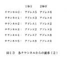
別の例として図13に示すように、各チヤンネルが2秒間の再生データを要求した場合を考える。この例においてハードデイスク装置は、1秒目にはアドレス1、2、3、5、7、8の順でアクセスし、2秒目には、アドレス2、3、4、6、8、9の順でアクセスすることになる。ここでハードデイスク装置が、1チヤンネルについて1秒分のアクセスを0.1 秒で行うことができる性能を有するとすると、6チヤンネル分のアクセスには0.6 秒だけかかる。この場合には、図14に示すように、2秒目のデータを1秒以内にアクセスすることができるので、2秒目の再生が間に合う。
【0014】
ところが、同じ例で、チヤンネル2が1秒目のデータとしてアドレス1を、2秒目のデータとしてアドレス10を要求したとすると、図15に示すように、アドレス1からアドレス10までのアクセスに1.1 秒かかつてしまい、チヤンネル2に対してデータの供給不足が生じ、この結果チヤンネル2の映像が途切れてしまう問題があつた。このようにデイスク装置から常に一定以上のデータ量を常に出力しなければならないシステムにおいては、デイスク装置がアクセスするアドレスを単純に並べ替えるだけでは、要求されるデータ量を出力することはできなかつた。
【0015】
本発明は以上の点を考慮してなされたもので、記録データの読出し順序を最適化することにより、各チヤンネルに途切れの無い再生データを供給し得るデイスク装置の再生方法を提案しようとするものである。
【0016】
【課題を解決するための手段】
かかる課題を解決するため本発明においては、所定時間内に複数のチヤンネルから供給された再生要求をデイスク録媒体のシーク時間が短くなるような順番に並べ替え、再生要求に応じた記録データを当該順番で再生して送出するデイスク装置の再生方法において、各チヤンネル毎に、前の時点に要求された記録データから次の時点に要求された記録データを再生するまでに必要な時間間隔を求め、当該時間間隔が予め設定されたアクセス間隔の最大時間以上になる再生要求についての記録データを優先的に再生するようにする。
【0017】
【作用】
各チヤンネル毎に、前の時点に要求された記録データから次の時点に要求された記録データを再生するまでに必要な時間間隔を求め、当該時間間隔が予め設定されたアクセス間隔の最大時間以上になる再生要求についての記録データを優先的に再生すれば、各チヤンネルに途切れの無い再生データを供給することができる。
【0018】
【実施例】
以下図面について、本発明の一実施例を詳述する。
【0019】
(1)AVサーバシステムの構成
図1において、20は全体として本発明を適用するAVサーバシステムの構成を示し、ビデオテープレコーダ(VTR)21等でなるデータ供給源22から出力される映像音声データD20をエンコード部23のエンコーダ24に与える。エンコーダ24は映像音声データD20をMPEG2の規格に従つたフオーマツトで符号化することにより符号化データD21を形成し、当該符号化データD21をサーバ部25に送出する。
【0020】
サーバ部25はメデイア制御部26及び複数のメデイアユニツト27A1〜27A7により構成されており、符号化データD21をメデイア制御部26に入力する。各メデイアユニツト27A1〜27A7はそれぞれ複数のハードデイスク装置を内蔵している。そしてサーバ部25のメデイア制御部26は入力した符号化データD21を、コントロール部28からの書込み制御信号S1に応じていずれかのメデイアユニツト27A1〜27A6又は27A7のハードデイスク装置を選択して記録する。またメデイア制御部26はコントロール部28からの読出し制御信号S2に応じて、所望の符号化データが記録されたハードデイスク装置を駆動して再生データを得る。
【0021】
またメデイア制御部26にはデコーダが内蔵されており、ハードデイスク装置によつて再生された再生データを復号する。さらにメデイア制御部26はデータ分配機能を有し、復号データD20をコントロール部28によつて指定された指定信号に従つて分配し、例えばテレビジヨン受像機でなる端末28A1〜28AN-1又は28ANに選択的に送出するようになされている。
【0022】
なお、AVサーバシステム20においては、データ供給源22による映像音声データD20の送出動作及びエンコーダ24の符号化動作をコントロール部28からの制御信号S3によつて制御する。またコントロール部28はデータ供給源22及びエンコーダ24の動作状態を状態信号S4に基づいて監視すると共に、メデイア制御部26の動作状態を状態信号S5に基づいて監視するようになされている。
【0023】
(2)サーバ部の構成
サーバ部25は、図2に示すように構成されている。なお図2では、説明を簡略化するため、7つのメデイアユニツト27A1〜27A7のうち1つのメデイアユニツト27A1に対応する構成部分のみを示した。
【0024】
サーバ部25はエンコーダ24からの符号化データD21を記録する際、当該符号化データD21をエンコーダインターフエース(エンコーダI/F)30及びエラーコードエンコーダ31を介して入出力部32A〜32Cに送出する。このときエラーコードエンコーダ31は符号化データD21を5分割し、この5分割したデータからパリテイを生成する。
【0025】
メデイア制御部26のメインCPU33は、コントロール部28からの書込み制御信号S1及び読出し制御信号S2を入力し、当該制御信号S1及びS2に基づいてハードデイスク装置HDD1〜HDD6及びHDDPを駆動制御するための駆動制御信号S6を入出力部32A〜32Cに送出する。
【0026】
この結果入出力部32A〜32Bはエラーコードエンコーダ31から与えられた符号化データを駆動制御信号S6に応じたハードデイスク装置HDD1〜HDDPによつて記録するようになされている。因に、ハードデイスク装置HDD1〜HDD5は映像音声データ記録用のハードデイスク装置であり、ハードデイスク装置HDDPはパリテイ用のハードデイスク装置である。
【0027】
一方、サーバ部25は再生時に、駆動制御信号S6に基づいて各ハードデイスクHDD1〜HDDPによつて読み出した再生データを、入出力部32A〜32Cを介してエラーコードデコーダ34に送出する。エラーコードデコーダ34は記録時に生成されたパリテイに基づいて再生データに対してエラー訂正処理を施すと共にこれを分配して、デコーダ部35を構成する複数のデコーダ35A〜35Fに選択的に送出する。
【0028】
実際上、メデイア制御部26においては、入出力部32A〜32C及びエラーコードデコーダ34の間、並びにエラーコードデコーダ34及びデコーダ部35の間がバスによつて接続されており、各ハードデイスク装置HDD1〜HDD5によつて読み出された再生データを時分割で伝送することにより、複数の再生データを指定された各チヤンネルCH1〜CH12に容易に分配し得るようになされている。なお、各デコーダ35A〜35Fは2チヤンネル分の復号データを同時に出力し得るようになされている。
【0029】
各入出力部32A〜32Cは、図3に示すように構成されている。ここで入出力部32Aと入出力部32B及び32Cは同様の構成でなることにより、以下入出力部32Aについて説明する。入出力部32Aは、エラーコードエンコーダ31から出力された符号化データをバツフア40、41に一旦蓄え、規定量のデータが蓄えられた時点で一気に記録用インターフエース(I/F)42、43を介してハードデイスク装置HDD1、HDD2に与えることによりハードデイスク上に記録する。
【0030】
また入出力部32Aはハードデイスク装置HDD1、HDD2によつて再生された再生データを、インターフエース42、43及びバツフア40、41を介してエラーデコーダ34に送出する。このように入出力部32Aにおいては、バツフア40、41に一旦データを蓄積してある程度まとまつたデータ量でデータの書込み及び読出しを行うことにより、ハードデイスク装置HDD1、HDD2のシーク時間を減らし、ハードデイスク装置HDD1、HDD2の実効速度を速くするようになされている。
【0031】
因に、入出力部32Aでは、バツフア40、41の容量をできるだけ少なくすることにより、構成を簡易化しコストを削減し得るにようになされている。また各バツフア40、41としてそれぞれフレームメモリを2つ用いることにより、記録データと再生データとのアクセスが衝突しないようになされている。
【0032】
すなわちバツフア40、41は1つのフレームメモリにハードデイスク装置HDD1、HDD2からの再生データを蓄積し、もう一方のフレームメモリにエラーコードエンコーダ31からのデータを蓄積するようになされている。従つてバツフア40、41には、最大2秒分のデータが記憶される。そして1フレーム分の記録又は再生が終了した時点でアクセスフレームを交換することにより、データ衝突が回避された記録及び再生ができるようになされている。
【0033】
また各入出力部32A〜32CはCPU44を有し、このCPU44にメインCPU33からの駆動制御信号S6を入力し、当該駆動制御信号S6に基づく駆動信号S8をインターフエース42、43を介して各ハードデイスク装置HDD1、HDD2に送出することにより、ハードデイスク装置HDD1、HDD2の読出し及び書込み動作を制御するようになされている。
【0034】
またCPU44は再生時にインターフエース42、43から出力される再生データを入力することにより、各ハードデイスク装置HDD1、HDD2のデータアクセス状態を監視することができるようになされている。そしてこの監視結果を監視結果信号S7としてメインCPU33に送出する。
【0035】
メインCPU33は監視結果信号S7を入力すると、当該監視結果をコントロール部28に状態信号S5により伝え、コントロール部28は監視結果をモニタに表示するようになされている。これによりユーザは、各ハードデイスク装置HDD1〜HDDPの動作状態をコントロール部28のモニタ上で容易に確認できる。
【0036】
さらにCPU44には、ソーテイング回路45、タイマ46及びFAT(File Allocation Table)メモリ47が接続されている。CPU44はデータ記録時にFATメモリ47に映像音声データのハードデイスク上の記録位置をクラス単位で記録する。CPU44はデータの読出し要求があると、FATメモリ47からソーテイング回路45に読出し要求があつたデータの記録位置を抜き出し、当該ソーテング回路45を用いて後述する読出し順序の並べ替えを行うようになされている。またCPU44はタイマ46によつてデータの読出し要求時間を管理するようになされている。
【0037】
ここでAVサーバシステム20によるハードデイスク上の記録フオーマツトを、図4に示す。AVサーバシステム20は、ハードデイスクデイスクの外周側から内周側に向つて順次、フオーマツト方式が記録される「ID領域」、デイスク内での各情報の記録開始セクタと大きさが記録される「フオーマツト領域」、符号化された映像音声データが記録される「映像データ領域」、デイスクの管理情報や映像の管理情報であるクリツプ情報が記録される「コントロールデータ領域」を形成する。
【0038】
なお、管理情報が記録された「コントロールデータ領域」は、クリツプ情報の登録情報が記録される「システム情報領域」、各クリツプの情報が記録される「フアイル情報領域」、映像音声データのハードデイスク上の記録位置をクラスタ単位で管理する「FAT領域」により形成されている。因に、各ブロツクの境界には将来の拡張用に予約領域が設けられている。また容量が2.15〔ギガ〕のハードデイスクに図4に示すような記録フオーマツトを施した場合の、各領域へのセクタ割当て例を、図5に示す。
【0039】
(3)実施例の記録データ再生処理
ここでこの実施例のサーバ部25においては、各チヤンネルCH1〜CH12からあるアドレスのデータを再生するための要求があると(すなわちコントロール部28から読出し制御信号S2が出力されると)、各チヤンネル毎に、前の時点に要求された記録データから次の時点に要求された記録データをアクセスするまでに必要な時間を求め、このアクセスに必要な時間間隔を考慮してアクセスするデータの順番を入れ換えることにより、各チヤンネルに途切れの無い映像音声データ(再生データ)を供給し得るようになされている。
【0040】
すなわちサーバ部25においては、チヤンネル毎にアクセス時の時間間隔を監視し、前のアクセスから次のアクセスに1秒以上かかりそうなときには、デイスク上の記録セクタの順序に関係なく(すなわち従来のように単に外周側から内周側、又は内周側から外周側に順に付された記録セクタの番号順に記録データを読み出すのではでなく)優先してそのアドレスの記録データを読み出すようにする。
【0041】
これを、図6に示すように、従来の再生順序ではデータ供給が間に合わなかつた場合を例にとつて説明する。なおここではチヤンネル数を6個とし、時間の監視単位を1/1000(1ミリ)秒とする。またアクセス間隔(すなわち1つのチヤンネルについて前のアクセスから次のアクセスまでにかかる時間)が750 ミリ秒以上となると優先してその記録データをアクセスするようにする。
【0042】
実施例の場合では、図7に示すように、チヤンネル1からの2秒目の要求であるアドレス4の読出しが終了した後に、チヤンネル2からの2秒目の要求であるアドレス10をアクセスすることになる。この結果チヤンネル2について、1秒目の要求を読み出してから2秒目の要求を読み出すまでに800 ミリ秒で済ませることができる。
【0043】
かくして、実施例のサーバ部25においては、そのシステムに適合したアクセス間隔の最大時間(実施例の場合750 ミリ秒)を設定し、この最大時間を基準としながら各チヤンネル毎のアクセス時間を管理し、その最大時間を越えたものを優先的にアクセスするようにしたことにより、各チヤンネルに映像音声データを途切れなく供給することができる。
【0044】
実際上、サーバ部25は、図8及び図9に示すような処理手順を実行することにより、上述したようにアクセス時間を管理し、各チヤンネルの映像音声データが途切れないような最適な読出し動作を行うようになされている。
【0045】
すなわちメインCPU33がステツプSP1においてデコーダ35A〜35Fからアクセス要求があるか否かを判断し、アクセス要求があるまで待機してアクセス要求があると、入出力部のCPU44にデータアクセスコマンド(すなわち駆動制御信号S6)を発信する。
【0046】
CPU44は、図9に示すように、ステツプSP11においてメインCPU33からのデータアクセスコマンドを受信し、コマンドの内容を内部メモリに記録すると共に受信時間をタイマ46に記録する。CPU44はステツプSP12でコマンドを待機状態とし、続くステツプSP13でタイマ46の内容を参照することにより受付終了時間か否か判断し、終了時間でない場合はステツプSP11に戻つて再び新しいコマンドを受信する。このようにCPU44は、受け付け終了時間迄ステツプSP11−S12−S13−S11を繰り返してコマンドを受け付けることにより、複数のコマンドを記憶するようになされている。
【0047】
CPU44はステツプSP13において肯定結果が得られ、コマンドの受付終了時間になると、ステツプSP14に移つて待機中のコマンドの中で規定時間(例えば750 ミリ秒)を越えているコマンドがあるか否か判断する。
【0048】
そしてCPU44はステツプSP14で否定結果が得られると、このことは優先してアクセスしなければならないコマンドが無いことを表し、このときステツプSP15に移り、ここでFATメモリ47からソーテイング回路45にコマンドに応じたデータを抜き出し、抜き出したFATデータに基づいてアクセスアドレスの並べ替えを行う。
【0049】
次にCPU44はステツプSP16において、並べ替えられたアドレスのうち最外周のアドレスを読み出すことを指示する駆動信号S8をハードデイスク装置HDD1〜HDD4又はHDD5に送出し、そのアドレスのデータを読み出させる。CPU44は続くステツプSP17において、実行したコマンドを待機中のコマンドから除き、続くステツプSP18において待機中のコマンドがあるか否か判断し、待機中のコマンドがある場合はステツプSP14に戻る。このようにCPU44は、ステツプSP14−SP15−SP16−SP17−SP18−SP14の処理ループを繰り返すことにより、従来と同様に外周側から内周側へと順次要求されたアドレスのデータを再生させる。またCPU44はステツプSP18において肯定結果が得られると、ステツプSP11に戻つて再び次のコマンドを受信する。
【0050】
これに加えて、CPU44はステツプSP14において肯定結果が得られると、このことは待機中のコマンドの中に直ぐに読み出さないと要求される時間を越えてしまう、すなわち映像音声データが途切れてしまうコマンドがあることを表し、このときステツプSP19に移つて、規定時間を越えているコマンドの中で一番規定時間を越えているコマンドを実行する。この結果、チヤンネルから出力される映像の途切れを未然に回避し得る。
【0051】
(4)実施例の動作
以上の構成において、AVサーバシステム20のサーバ部25は、各チヤンネルCH1〜CH12からの要求に応じて例えばハードデイスク装置HDD1〜HDDPを駆動して各チヤンネルCH1〜CH12に再生データを供給する。このときサーバ部25は第1の時刻(例えば1秒目)に各チヤンネルCH1〜CH12から複数の要求があり、第2の時刻(例えば2秒目)に各チヤンネルCH1〜CH12から複数の要求があると、先ず第1の時刻の要求をハードデイスク上でのシーク時間が短くなるように外周側から内周側に順番に並び替え、次に第2の時刻にあつた要求を同じく外周側から内周側に順番に並び替えて再生する順番を決定する。
【0052】
ここでサーバ部25は第2の時刻にあつた要求を並べ替える際、各チヤンネルCH1〜CH12毎に、第1の時刻の要求を再生してから、第2の時刻の要求を再生するまでにかかる時間を予め求め、この時間間隔が所定以上の要求を優先して再生するようにする。この結果ハードデイスク装置HDD1〜HDDPは各チヤンネルCH1〜CH12に途切れのない映像音声データを供給できるようになる。
【0053】
(5)実施例の効果
以上の構成によれば、各チヤンネルCH1〜CH12からの要求に対応した記録データをシーク時間が短くなる順序で再生すると共に、このとき各チヤンネル毎のアクセス時間間隔を予め求め、当該時間間隔が所定以上となる要求を優先して再生するようにしたことにより、各チヤンネルCH1〜CH12に途切れのない再生映像音声データを供給することができる。
【0054】
またこのように各チヤンネル毎のアクセス時間を管理したことにより、ハードデイスク装置HDD1〜HDDPの見かけ上のアクセス速度を向上させることができる。また低いデータ転送速度でも、システムから要求される各チヤンネルCH1〜CH12への再生データ供給量を満たすことができる。
【0055】
さらにハードデイスク装置を複数台並列に接続して転送能力を高めているようなシステムにおいて、一台のハードデイスク装置当りのデータ読出し能力が向上することにより、並列接続するハードデイスク装置の個数を低減でき、構成を簡易化できる。
【0056】
(6)他の実施例
なお上述の実施例においては、本発明によるデイスク装置の再生方法を、AVサーバシステム20に適用した場合について述べたが、本発明はこれに限らず、種々のデイスク装置の再生方法に適用することができる。例えばデイスク装置として光磁気デイスク装置を用いた場合にも適用でき、要はデイスク状記録媒体に記録された記録データを複数のチヤンネルからの要求に応じて再生するデイスク装置に広く適用し得る。
【0057】
また上述の実施例においては、各チヤンネルからの要求をハードデイスクの外周側から内周側に順に読み出すことによりシーク時間を短くする場合について述べたが、勿論各チヤンネルからの要求をハードデイスクの内周側から外周側に順に読み出すようにしてシーク時間を短くするようにしても良い。
【0058】
さらに上述の実施例においては、各チヤンネルからの要求をハードデイスクの外周側から内周側に順に読み出すことによりシーク時間を短くする場合について述べたが、必ずしもそうする必要はなく、要は各チヤンネルに再生映像音声データが途切れないような順番で再生するようにすれば良い。
【0059】
【発明の効果】
以上のように本発明によれば、所定時間内に複数のチヤンネルから供給された再生要求をデイスク状録媒体のシーク時間が短くなるような順番に並べ替え、再生要求に応じた記録データを当該順番で再生して送出するデイスク装置の再生方法において、各チヤンネル毎に、前の時点に要求された記録データから次の時点に要求された記録データを再生するまでに必要な時間間隔を求め、当該時間間隔が予め設定されたアクセス間隔の最大時間以上になる再生要求についての記録データを優先的に再生するようにしたことにより、記録データの読出し順序を最適化し得、各チヤンネルに途切れの無い再生データを供給することができる。
【図面の簡単な説明】
【図1】本発明を適用したAVサーバシステムの全体構成を示すブロツク図である。
【図2】サーバ部の構成を示すブロツク図である。
【図3】入出力部の構成を示すブロツク図である。
【図4】実施例のAVサーバシステムによる記録フオーマツトを示す略線図である。
【図5】各データ領域へのセクタ割当て例を示す略線図である。
【図6】各チヤンネルからの要求される読出しアドレスの例を示す図表である。
【図7】実施例によるアクセス順序の説明に供する略線図である。
【図8】チヤンネルからの読出し要求に対するサーバ部メインCPUの処理手順を示すフローチヤートである。
【図9】実施例によるアクセス順序選定の説明に供する処理手順を示すフローチヤートである。
【図10】従来のAVサーバシステムの構成を示すブロツク図である。
【図11】デイスク上でのアドレス例を示す略線図である。
【図12】各チヤンネルからの要求例を示す図表である。
【図13】各チヤンネルからの要求例を示す図表である。
【図14】図13の要求に基づいて再生データを読み出す場合のアクセス順序例を示す略線図である。
【図15】アクセス順序に不適合が生じる例を示す略線図である。
【符号の説明】
20……AVサーバシステム、22……データ供給源、23……エンコード部、25……サーバ部、26……メデイア制御部、27A1〜27A7……メデイアユニツト、28……コントロール部、28A1〜28AN……端末、32A〜32C……入出力部、33……メインCPU、35……デコーダ部、35A〜35F……デコーダ、40、41……バツフア、42、43……インターフエース、44……CPU、45……ソーテイング回路、46……タイマ、47……FATメモリ、HDD1〜HDD5、HDDP……ハードデイスク装置、D20……映像音声データ、D21……符号化データ、D22……復号データ、S1……書込み制御信号、S2……読出し制御信号、S3……制御信号、S4、S5……状態信号、S6……駆動制御信号、S7……監視結果信号、S8……駆動信号。[0001]
【table of contents】
The present invention will be described in the following order.
Industrial application fields
Conventional technology (Fig. 10)
Problems to be Solved by the Invention (FIGS. 10 to 15)
Means for solving the problem
Action
Example
(1) Configuration of AV server system (FIG. 1)
(2) Configuration of server unit (FIGS. 2 to 5)
(3) Recorded data reproduction process of the embodiment (FIGS. 6 to 9)
(4) Operation of the embodiment
(5) Effects of the embodiment
(6) Other embodiments
The invention's effect
[0002]
[Industrial application fields]
The present invention relates to a playback method for a disk device, and is suitable for application to a playback method for a disk device used in an AV server system, for example.
[0003]
[Prior art]
2. Description of the Related Art Conventionally, an AV (Audio Vidual: audio / video) server system has been proposed as a device that supplies video to each of a plurality of viewers from a single video supply source provided in a broadcasting station or the like. As shown in FIG. 10, the
[0004]
The
[0005]
At this time, the read operation from the
[0006]
[Problems to be solved by the invention]
By the way, in the
[0007]
Here, the data reproduction operation by the disk device will be described. Here, a case where a hard disk device is used as the disk device will be described. The hard disk device is configured to rotate a disk-shaped recording medium and record and reproduce data on the medium by a recording / reproducing head. At this time, since the recording / reproducing head is generally one, the data can be accessed only sequentially.
[0008]
Further, since the recording / reproducing head operates mechanically, when the access position of the recording / reproducing head is changed (so-called seeking), it takes a lot of time compared to the case of accessing consecutive positions. Further, after the recording / reproducing head is moved, it is necessary to wait for the rotation until the head reaches the circumference on which the designated data is recorded.
[0009]
Each channel 6A is similar to the disk device used in the
[0010]
In order to realize the maximum number of transmission channels in terms of performance, high performance is required by multiplying the access speed required per channel by the number of channels. Disappears. Therefore, it is necessary to make the seek time as short as possible. Usually, in order to shorten the seek time, when there are multiple access requests at the same time, change the access order so that the seek time is reduced and the seek time is shortened, and then access is performed in that order. To do.
[0011]
For example, as shown in FIG. 11, consider a disk with
[0012]
Consider a hard disk device that transfers playback data for 1 second per channel by one access from seek to data read. In the example shown in the figure, 6 accesses are completed within 1 second. It is necessary to supply reproduction data for 1 second to each of the 6 channels and to start access for the next second.
[0013]
As another example, consider a case where each channel requests reproduction data for 2 seconds as shown in FIG. In this example, the hard disk device accesses in the order of
[0014]
However, in the same example, if
[0015]
The present invention has been made in consideration of the above points, and intends to propose a playback method for a disk device capable of supplying continuous playback data to each channel by optimizing the reading order of recorded data. It is.
[0016]
[Means for Solving the Problems]
In order to solve this problem, in the present invention,Replay requests supplied from multiple channels within a given time Disc recording mediaArrange in order that seek time is shorter, and record data according to playback request in that order. In the playback method of the disk device to be played back and sent out, for each channel, the time interval required to play back the recording data requested at the next time from the recording data requested at the previous time is set.Seeking , The time interval isMaximum time between preset access intervals AboveReplay request The recorded data on is played back preferentially.
[0017]
[Action]
For each channel, the time interval required to reproduce the recording data requested at the next time from the recording data requested at the previous time is set.Seeking , The time interval isMaximum time between preset access intervals AboveReplay request If the recorded data is reproduced preferentially, continuous data can be supplied to each channel.
[0018]
【Example】
Hereinafter, an embodiment of the present invention will be described in detail with reference to the drawings.
[0019]
(1) Configuration of AV server system
In FIG. 1,
[0020]
The
[0021]
The media control unit 26 has a built-in decoder, and decodes the reproduction data reproduced by the hard disk device. Further, the media control unit 26 has a data distribution function, distributes the decoded data D20 in accordance with a designation signal designated by the
[0022]
In the
[0023]
(2) Configuration of server part
The
[0024]
When recording the encoded data D21 from the encoder 24, the
[0025]
The
[0026]
As a result, the input /
[0027]
On the other hand, during reproduction, the
[0028]
In practice, in the media control unit 26, the input /
[0029]
Each of the input /
[0030]
Further, the input /
[0031]
Incidentally, in the input /
[0032]
That is, the
[0033]
Each of the input /
[0034]
The
[0035]
When the
[0036]
Further, a sorting
[0037]
Here, the recording format on the hard disk by the
[0038]
The “control data area” in which the management information is recorded includes a “system information area” in which registration information of clip information is recorded, a “file information area” in which information of each clip is recorded, and a hard disk of video / audio data. Is formed by a “FAT area” for managing the recording position in cluster units. Incidentally, a reserved area is provided for future expansion at the boundary of each block. FIG. 5 shows an example of sector allocation to each area when a recording format as shown in FIG. 4 is applied to a hard disk with a capacity of 2.15 [Giga].
[0039]
(3) Recorded data reproduction processing of the embodiment
Here, in the
[0040]
That is, the
[0041]
This will be described with reference to an example in which data is not supplied in the conventional reproduction order as shown in FIG. Here, the number of channels is six, and the time monitoring unit is 1/1000 (1 millisecond). Also, when the access interval (that is, the time taken from the previous access to the next access for one channel) becomes 750 milliseconds or more, the recorded data is preferentially accessed.
[0042]
In the case of the embodiment, as shown in FIG. 7, after the reading of the
[0043]
Thus, in the
[0044]
In practice, the
[0045]
That is, the
[0046]
As shown in FIG. 9, the
[0047]
When a positive result is obtained at step SP13 and the command reception end time is reached, the
[0048]
When the
[0049]
Next, in step SP16, the
[0050]
In addition to this, if the
[0051]
(4) Operation of the embodiment
In the above configuration, the
[0052]
Here, when the
[0053]
(5) Effects of the embodiment
According to the above configuration, the recording data corresponding to the request from each channel CH1 to CH12 is reproduced in the order in which the seek time is shortened, and at this time, the access time interval for each channel is obtained in advance, and the time interval is predetermined. By reproducing the above request with priority, it is possible to supply uninterrupted reproduced video / audio data to each of the channels CH1 to CH12.
[0054]
Further, by managing the access time for each channel in this way, the apparent access speed of the hard disk devices HDD1 to HDDP can be improved. Further, even at a low data transfer rate, the reproduction data supply amount to each channel CH1 to CH12 required by the system can be satisfied.
[0055]
Furthermore, in a system in which multiple hard disk devices are connected in parallel to increase the transfer capacity, the number of hard disk devices connected in parallel can be reduced by improving the data reading capacity per hard disk device. Can be simplified.
[0056]
(6) Other embodiments
In the above-described embodiment, the case where the disk device playback method according to the present invention is applied to the
[0057]
In the above embodiment, the case where the seek time is shortened by sequentially reading the requests from the respective channels from the outer peripheral side to the inner peripheral side of the hard disk has been described. Of course, the request from each channel is changed to the inner peripheral side of the hard disk. The seek time may be shortened by sequentially reading from the outer periphery side.
[0058]
Furthermore, in the above-described embodiment, the case where the seek time is shortened by sequentially reading the requests from each channel from the outer peripheral side to the inner peripheral side of the hard disk has been described. The playback video / audio data may be played back in an order that does not interrupt.
[0059]
【The invention's effect】
As described above, according to the present invention,Replay requests supplied from multiple channels within a given time Of disk recording mediaArrange in order that seek time is shorter, and record data according to playback request in that order. In the playback method of the disk device to be played back and sent out, for each channel, the time interval required to play back the recording data requested at the next time from the recording data requested at the previous time is set.Seeking , The time interval isMaximum time between preset access intervals AboveReplay request As a result, the recording data read-out order can be optimized, and continuous reproduction data can be supplied to each channel.
[Brief description of the drawings]
FIG. 1 is a block diagram showing the overall configuration of an AV server system to which the present invention is applied.
FIG. 2 is a block diagram showing a configuration of a server unit.
FIG. 3 is a block diagram showing a configuration of an input / output unit.
FIG. 4 is a schematic diagram illustrating a recording format by the AV server system according to the embodiment.
FIG. 5 is a schematic diagram illustrating an example of sector allocation to each data area;
FIG. 6 is a chart showing an example of a read address requested from each channel.
FIG. 7 is a schematic diagram for explaining an access order according to the embodiment;
FIG. 8 is a flowchart showing a processing procedure of the server unit main CPU in response to a read request from a channel.
FIG. 9 is a flowchart showing a processing procedure for explaining access order selection according to the embodiment.
FIG. 10 is a block diagram showing a configuration of a conventional AV server system.
FIG. 11 is a schematic diagram illustrating an example of an address on a disk.
FIG. 12 is a chart showing an example of a request from each channel.
FIG. 13 is a chart showing an example of a request from each channel.
14 is a schematic diagram illustrating an example of an access order in the case of reading reproduction data based on the request of FIG.
FIG. 15 is a schematic diagram illustrating an example in which incompatibility occurs in an access order.
[Explanation of symbols]
20 ... AV server system, 22 ... Data supply source, 23 ... Encoding unit, 25 ... Server unit, 26 ... Media control unit, 27A1 ~ 27A7 …… Media unit, 28 …… Control unit, 28A1 ~ 28AN ... Terminals, 32A to 32C ... Input / output part, 33 ... Main CPU, 35 ... Decoder part, 35A to 35F ... Decoder, 40, 41 ... Buffer, 42, 43 ... Interface, 44 ...
Claims (3)
Translated fromJapanese各チヤンネル毎に、前の時点に要求された記録データから次の時点に要求された記録データを再生するまでに必要な時間間隔を求め、
当該時間間隔が予め設定されたアクセス間隔の最大時間以上になる再生要求についての記録データを優先的に再生する
ことを特徴とするデイスク装置の再生方法。A discthat rearrangesplayback requests froma plurality of channelssupplied within a predetermined time inan order that shortens theseek timeof the disk-shaped recording medium,and plays back and sends outthe recording data according to the playback request in that order. In the playback method of the device,
For each channel,determine the time interval required from the record data requested before the time until reproducing the record data requested in the next time,
A playback method for a disk device, wherein the recorded data is played back preferentially for aplayback requestin which the time interval is equal to or greater thana preset access interval maximum time .
ことを特徴とする請求項1に記載のデイスク装置の再生方法。If the playback request includes a playback request whose time interval exceeds the maximum time, the recorded data for the playback request exceeding the maximum time is played back, and playback whose time interval exceeds the maximum time is played back When there are no more requests, the remaining reproduction requests are rearranged to preferentially reproduce the recording data for the reproduction request in which the time interval is equal to or greater than a preset access interval. The method for reproducing a disk device according to claim 1.
ことを特徴とする請求項1に記載のデイスク装置の再生方法。The method for regenerating a disk device according to claim 1.
Priority Applications (1)
| Application Number | Priority Date | Filing Date | Title |
|---|---|---|---|
| JP10798195AJP3867864B2 (en) | 1995-04-08 | 1995-04-08 | Reproduction method of disk device |
Applications Claiming Priority (1)
| Application Number | Priority Date | Filing Date | Title |
|---|---|---|---|
| JP10798195AJP3867864B2 (en) | 1995-04-08 | 1995-04-08 | Reproduction method of disk device |
Publications (2)
| Publication Number | Publication Date |
|---|---|
| JPH08287601A JPH08287601A (en) | 1996-11-01 |
| JP3867864B2true JP3867864B2 (en) | 2007-01-17 |
Family
ID=14472966
Family Applications (1)
| Application Number | Title | Priority Date | Filing Date |
|---|---|---|---|
| JP10798195AExpired - Fee RelatedJP3867864B2 (en) | 1995-04-08 | 1995-04-08 | Reproduction method of disk device |
Country Status (1)
| Country | Link |
|---|---|
| JP (1) | JP3867864B2 (en) |
- 1995
- 1995-04-08JPJP10798195Apatent/JP3867864B2/ennot_activeExpired - Fee Related
Also Published As
| Publication number | Publication date |
|---|---|
| JPH08287601A (en) | 1996-11-01 |
Similar Documents
| Publication | Publication Date | Title |
|---|---|---|
| US5757415A (en) | On-demand data transmission by dividing input data into blocks and each block into sub-blocks such that the sub-blocks are re-arranged for storage to data storage means | |
| US6212681B1 (en) | Information processing apparatus and method therefor in a data transfer network | |
| JP4126713B2 (en) | Image reproducing apparatus and image reproducing method | |
| JP3612455B2 (en) | Data recording / reproducing apparatus, video data recording / reproducing method, and disk drive unit | |
| JP4265019B2 (en) | Data storage apparatus and method, and data transmission apparatus and method | |
| JP3867864B2 (en) | Reproduction method of disk device | |
| WO1996032673A1 (en) | Device and method for reproducing information signal | |
| US5842046A (en) | Disk drive system for storing a plurality of I frames non-interlaced with respect to B frames by storing B frames in a separate cylinder | |
| JPH1051740A (en) | Data transmission system | |
| JP4099548B2 (en) | Video signal recording and playback device | |
| JP3586892B2 (en) | Multi-channel video reproducing apparatus and control method thereof | |
| JP3799205B2 (en) | Data recording / reproducing apparatus and data recording / reproducing method | |
| JP3200852B2 (en) | Information signal reproducing apparatus and information signal reproducing method | |
| JPWO2010007727A1 (en) | Video recording apparatus, video reproduction apparatus and method thereof | |
| JP2652595B2 (en) | Audiovisual information provision system | |
| JP3153490B2 (en) | Recording / reproducing apparatus and recording / reproducing method thereof | |
| US20010041058A1 (en) | Data recording and reproducing method and data recording and reproducing apparatus | |
| JP3642090B2 (en) | Video data recording and playback method | |
| JPH10326448A (en) | Data transmitting device and data transmitting method | |
| JPH0854990A (en) | Video information provision device | |
| JPH08287614A (en) | Disk device and disk-like recording medium | |
| JP3228283B2 (en) | Data recording / reproducing apparatus and data recording / reproducing method | |
| KR0185916B1 (en) | A video service apparatus | |
| JP4182576B2 (en) | Data processing apparatus and method | |
| JPH0846584A (en) | Data transmission device |
Legal Events
| Date | Code | Title | Description |
|---|---|---|---|
| A977 | Report on retrieval | Free format text:JAPANESE INTERMEDIATE CODE: A971007 Effective date:20050929 | |
| A131 | Notification of reasons for refusal | Free format text:JAPANESE INTERMEDIATE CODE: A131 Effective date:20051014 | |
| A521 | Written amendment | Free format text:JAPANESE INTERMEDIATE CODE: A523 Effective date:20051212 | |
| TRDD | Decision of grant or rejection written | ||
| A01 | Written decision to grant a patent or to grant a registration (utility model) | Free format text:JAPANESE INTERMEDIATE CODE: A01 Effective date:20060922 | |
| A61 | First payment of annual fees (during grant procedure) | Free format text:JAPANESE INTERMEDIATE CODE: A61 Effective date:20061005 | |
| FPAY | Renewal fee payment (event date is renewal date of database) | Free format text:PAYMENT UNTIL: 20091020 Year of fee payment:3 | |
| FPAY | Renewal fee payment (event date is renewal date of database) | Free format text:PAYMENT UNTIL: 20101020 Year of fee payment:4 | |
| FPAY | Renewal fee payment (event date is renewal date of database) | Free format text:PAYMENT UNTIL: 20111020 Year of fee payment:5 | |
| LAPS | Cancellation because of no payment of annual fees |