JP3867023B2 - Suture device - Google Patents
Suture deviceDownload PDFInfo
- Publication number
- JP3867023B2 JP3867023B2JP2002191111AJP2002191111AJP3867023B2JP 3867023 B2JP3867023 B2JP 3867023B2JP 2002191111 AJP2002191111 AJP 2002191111AJP 2002191111 AJP2002191111 AJP 2002191111AJP 3867023 B2JP3867023 B2JP 3867023B2
- Authority
- JP
- Japan
- Prior art keywords
- staple
- anvil
- insertion portion
- tissue
- suturing
- Prior art date
- Legal status (The legal status is an assumption and is not a legal conclusion. Google has not performed a legal analysis and makes no representation as to the accuracy of the status listed.)
- Expired - Fee Related
Links
- 238000003825pressingMethods0.000claimsabstractdescription64
- 238000003780insertionMethods0.000claimsdescription116
- 230000037431insertionEffects0.000claimsdescription116
- 230000035515penetrationEffects0.000claims1
- 238000005452bendingMethods0.000description14
- 208000032843HemorrhageDiseases0.000description12
- 208000034158bleedingDiseases0.000description12
- 230000000740bleeding effectEffects0.000description12
- 210000004204blood vesselAnatomy0.000description12
- 230000004048modificationEffects0.000description11
- 238000012986modificationMethods0.000description11
- 238000000465mouldingMethods0.000description8
- 230000000694effectsEffects0.000description7
- 230000023597hemostasisEffects0.000description6
- 230000033001locomotionEffects0.000description6
- 230000001105regulatory effectEffects0.000description6
- 229910052751metalInorganic materials0.000description5
- 239000002184metalSubstances0.000description5
- 210000003815abdominal wallAnatomy0.000description4
- 210000000078clawAnatomy0.000description4
- 238000010586diagramMethods0.000description4
- 238000007599dischargingMethods0.000description4
- 210000000232gallbladderAnatomy0.000description4
- 239000012212insulatorSubstances0.000description4
- 239000000463materialSubstances0.000description3
- 238000000034methodMethods0.000description3
- 230000002265preventionEffects0.000description3
- 238000009958sewingMethods0.000description3
- 238000001356surgical procedureMethods0.000description3
- PXHVJJICTQNCMI-UHFFFAOYSA-NNickelChemical compound[Ni]PXHVJJICTQNCMI-UHFFFAOYSA-N0.000description2
- 210000000683abdominal cavityAnatomy0.000description2
- 201000001883cholelithiasisDiseases0.000description2
- 238000006073displacement reactionMethods0.000description2
- 230000002439hemostatic effectEffects0.000description2
- 239000011810insulating materialSubstances0.000description2
- 239000004033plasticSubstances0.000description2
- 230000000630rising effectEffects0.000description2
- 210000002784stomachAnatomy0.000description2
- 206010028980NeoplasmDiseases0.000description1
- 239000004809TeflonSubstances0.000description1
- 229920006362Teflon®Polymers0.000description1
- RTAQQCXQSZGOHL-UHFFFAOYSA-NTitaniumChemical compound[Ti]RTAQQCXQSZGOHL-UHFFFAOYSA-N0.000description1
- 210000001015abdomenAnatomy0.000description1
- 230000001154acute effectEffects0.000description1
- 210000001367arteryAnatomy0.000description1
- 210000000013bile ductAnatomy0.000description1
- 230000033228biological regulationEffects0.000description1
- 230000005540biological transmissionEffects0.000description1
- 210000004369bloodAnatomy0.000description1
- 239000008280bloodSubstances0.000description1
- 230000017531blood circulationEffects0.000description1
- 210000001124body fluidAnatomy0.000description1
- 239000010839body fluidSubstances0.000description1
- 201000011510cancerDiseases0.000description1
- 238000005524ceramic coatingMethods0.000description1
- -1ceramic coatingSubstances0.000description1
- 238000006243chemical reactionMethods0.000description1
- 230000001112coagulating effectEffects0.000description1
- 239000011248coating agentSubstances0.000description1
- 238000000576coating methodMethods0.000description1
- 239000004020conductorSubstances0.000description1
- 238000002674endoscopic surgeryMethods0.000description1
- 238000004299exfoliationMethods0.000description1
- 238000001125extrusionMethods0.000description1
- 238000002682general surgeryMethods0.000description1
- 230000009545invasionEffects0.000description1
- 229910052759nickelInorganic materials0.000description1
- 239000003973paintSubstances0.000description1
- 230000000149penetrating effectEffects0.000description1
- 230000002093peripheral effectEffects0.000description1
- 238000002271resectionMethods0.000description1
- 239000011347resinSubstances0.000description1
- 229920005989resinPolymers0.000description1
- 239000007779soft materialSubstances0.000description1
- 210000000779thoracic wallAnatomy0.000description1
- 239000010936titaniumSubstances0.000description1
- 229910052719titaniumInorganic materials0.000description1
- 210000003462veinAnatomy0.000description1
Images


Classifications
- A—HUMAN NECESSITIES
- A61—MEDICAL OR VETERINARY SCIENCE; HYGIENE
- A61B—DIAGNOSIS; SURGERY; IDENTIFICATION
- A61B17/00—Surgical instruments, devices or methods
- A61B17/068—Surgical staplers, e.g. containing multiple staples or clamps
- A61B17/072—Surgical staplers, e.g. containing multiple staples or clamps for applying a row of staples in a single action, e.g. the staples being applied simultaneously
- A61B17/07207—Surgical staplers, e.g. containing multiple staples or clamps for applying a row of staples in a single action, e.g. the staples being applied simultaneously the staples being applied sequentially
- A—HUMAN NECESSITIES
- A61—MEDICAL OR VETERINARY SCIENCE; HYGIENE
- A61B—DIAGNOSIS; SURGERY; IDENTIFICATION
- A61B17/00—Surgical instruments, devices or methods
- A61B17/068—Surgical staplers, e.g. containing multiple staples or clamps
- A61B17/072—Surgical staplers, e.g. containing multiple staples or clamps for applying a row of staples in a single action, e.g. the staples being applied simultaneously
- A61B2017/07214—Stapler heads
- A61B2017/07221—Stapler heads curved
Landscapes
- Health & Medical Sciences (AREA)
- Life Sciences & Earth Sciences (AREA)
- Surgery (AREA)
- Heart & Thoracic Surgery (AREA)
- Engineering & Computer Science (AREA)
- Biomedical Technology (AREA)
- Nuclear Medicine, Radiotherapy & Molecular Imaging (AREA)
- Medical Informatics (AREA)
- Molecular Biology (AREA)
- Animal Behavior & Ethology (AREA)
- General Health & Medical Sciences (AREA)
- Public Health (AREA)
- Veterinary Medicine (AREA)
- Surgical Instruments (AREA)
Abstract
Description
Translated fromJapanese【0001】
【発明の属する技術分野】
この発明は、腹壁等を貫通して体腔内に挿入し、体腔内の生体組織を縫合する縫合装置に関する。
【0002】
【従来の技術】
例えば、胆のう結石手術等において、再発防止のために胆のうごと摘出手術を行う場合、胆管と胆のうとの接続部を切断するが、この接続部には胆のう動脈、胆のう静脈が通っているため、接続部をナイフ等によって切断すると同時に縫合する必要がある。
【0003】
このような胆のう結石手術等においては腹壁等を貫通して体腔内に挿入して体腔内の組織を縫合する縫合器が用いられている。この種の縫合器には従来、例えば実公昭38−19282号公報、実公昭60−41924号公報および特開平3−12126号公報等で知られている。
【0004】
実公昭38−19282号公報は、外科的に胃の縫合に使用される縫合器であり、縫合部材としてのステープルとステープル押出し機構を有するステープル把持部材とアンビル部材からなり、両者ともその形状が胃の大湾に沿うように湾曲しており、ステープル把持部材の末端のヒンジピンによってアンビル部材と開閉自在に接続されている。
【0005】
実公昭60−41924号公報は、外科的に癌核を縫合する縫合器であり、鋏状の結紮器本体で、本体に支点を挟んだ一方を挟持部、他方を柄として十分に長く形成し、嘴状に腹部が向い合い、一方にステープルを保持し、他方がアンビルからなり、患部に合わせて湾曲している挟持部からなり、前記柄を開閉することにより開閉自在に設けられている。
【0006】
特開平3−12126号公報は、経皮的に体腔内に挿入され、体腔内組織を縫合する縫合器で、挿入部と、この挿入部の先端部に開閉自在に設けられ一方がアンビル、他方がステープルを保持するカートリッジからなる縫合器本体と、前記挿入部の先端部に設けられカートリッジからステープルを打出すファイリングレバーと、縫合器本体を開閉せしめる縫合開閉レバーとから構成されている。
【0007】
【発明が解決しようとする課題】
ところで、実公昭38−19282号公報は、アンビルとステープル保持部材のみで構成され、挿入部を持ってないため、経皮的に体腔内に挿入できない。また、縫合器本体に組織を切断する切断手段がないため、組織を切断するときには別途切断器を用意しなくてはならない。
【0008】
実公昭60−41924号公報は、体腔内に経皮的に挿入して使用する際、縫合器本体の開閉のための柄を開閉できるように体腔壁(腹壁、胸壁等)を切開しなければならないため、侵襲が大きく、また切断手段がないため、別途切断器を用意しなくてはならない。
【0009】
特開平3−12126号公報は、縫合器本体が挿入部の中心軸に対してストレートに形成されている。したがって、体腔内に癒着部があり、腔間が狭い時には縫合器本体をアプローチしにくく、また組織縫合部が挿入部の軸方向に存在しない場合、別途把持鉗子等によって組織を縫合器本体に挿入、把持してやらなければならない。
【0010】
このように従来の縫合器は、いずれも操作性が悪く、別の処置具が必要になったり、手術時間が長くかかり、患者に与える負担が大きいという問題がある。また、いずれの器具も、縫合部材の周辺や組織を切除した後の血液や体液の流れを止めることを効率的に行えるものはなかった。
【0011】
これは縫合部材の配列を完全に隙間なくすることは難しく、また止血用クリップ、ステープルなど単数の金属製縫合部材を用いるものに関しては、変形後の弾性的戻りにより止血、縫合が十分に行えなかった。
【0012】
また、組織縫合部に限らず、出血が起こった際には電気メスなどで出血部を凝固し、止血することが一般的に行われているが、内視鏡下手術では、そのために処置具を電気メス用電極に差し替えるのが煩雑であった。
【0013】
さらに、組織の縫合部位が切開部(傷口)であって、この切開部をステープルによって縫合する場合、切開部を閉じた状態で縫合する必要があるが、従来の縫合器では切開部を閉じることは困難であり、別の把持鉗子等の処置具が必要になったり、手術時間が長くかかり、縫合手術を効率的に行えるものではなかった。
【0014】
この発明は、前記事情に着目してなされたもので、その目的とするところは、生体組織に刺入可能な一対の刺入部を有する縫合手段によって組織の切開部等を引き寄せた状態で効率的に縫合でき、手術時間を短縮することができる縫合装置を提供することにある。
【0015】
【課題を解決するための手段】
この発明は前記目的を達成するために、体腔内に挿入可能な挿入部と、前記挿入部の基端部に設けられた操作部と、前記挿入部に設けられた先端部と、前記先端部に設けられ生体組織の被縫合部に刺入可能な一対の刺入部を両端部に有し、前記生体組織を縫合可能なステープルと、前記挿入部の先端部に設けられ、前記ステープルの中央部を保持する保持部と、前記操作部の操作に連動して操作される切替部材と、前記切替部材に連動して前記ステープルの一対の刺入部を左右交互に操作し、前記刺入部を前記生体組織に交互に穿刺する右押圧部材及び左押圧部材とからなり、前記ステープルの中央部を前記保持部によって保持した状態で、一方の刺入部を前記生体組織の被縫合部に穿刺して組織同士を引き寄せた状態で、前記ステープルの他方の刺入部を穿刺して前記生体組織の被縫合部を縫合することを特徴とする縫合装置にある。
前記右押圧部材及び左押圧部材は、好ましくは、前記操作部に設けられた操作ハンドルの操作が前記切替部材を介して連動し、交互に操作されることを特徴とする。
【0018】
【作用】
挿入部を体腔内に挿入し、その先端部の縫合手段を被縫合部に位置決めし、縫合する際に、縫合手段の一対の刺入部を被縫合部の組織に独立して刺入することにより、組織同士を引き寄せた状態で被縫合部を縫合することができる。
【0019】
【発明の実施の形態】
以下、この発明の各実施形態を図面に基づいて説明する。
【0020】
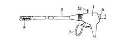
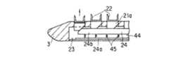
図1〜図10は第1の実施形態で、図1は縫合装置の全体構成を示す。1は操作部本体で、この操作部本体1には挿入部2の基端部が矢印方向に回転自在に連結されている。挿入部2の先端部には生体組織を挟持するカートリッジ3とアンビル4とからなる縫合器本体5が設けられている。
【0021】
操作部本体1には縫合器本体5を開閉する挟持操作手段としての開閉操作部6とステープル操作部7が設けられている。さらに、操作部本体1には縫合器本体5に電気的に接続する電力供給手段からの電力入力部としての高周波接続ピン32が外部に突出して設けられている。
【0022】
図2〜図7に示すように、前記挿入部2は、内筒8とこの内筒8に対して軸方向に進退自在に嵌合された外筒9とから構成されている。この内筒8の先端部における両側部には広角V字状のばね材からなる一対の継手10の基端部が枢支され、これら継手10の先端部間には内筒8と直交する方向にヒンジピン11が架設されている。このヒンジピン11の両端部は外筒9の側壁に設けられた略T字状のスリット12に挿入され、外筒9の進退時および継手10の上下時のガイド部を形成している。
【0023】
さらに、内筒8の先端部における上部内面には係合凹部13が設けられているとともに、この係合凹部13の近傍に位置する先端には前方に突出する突出片14が設けられ、この突出片14の上面には板ばね15が設けられている。
【0024】
一方、前記カートリッジ3の基端部には基端側に開口するL字状のヒンジ溝16が設けられ、このヒンジ溝16には開口から挿入することにより、前記ヒンジピン11が上下方向に回動自在および着脱自在に係合されている。
【0025】
また、前記アンビル4の基端部の上面には前記係合凹部13に係合する係合凸部17が設けられ、アンビル4の基端部の下面は前記板ばね15に弾性的に圧接されている。つまり、板ばね15の弾性押圧力によってアンビル4の係合凸部17を係合凹部13に係合する方向に付勢している。
【0026】
したがって、前記挿入部2の内筒8にはカートリッジ3とアンビル4がその基端部を支点として上下方向に回動(開閉)自在であり、カートリッジ3は継手10の弾性力によって、アンビル4は板ばね15の弾性力によって開方向に付勢され、内筒8に対して進退自在な外筒9を前進することにより、カートリッジ3とアンビル4の基端部が外筒9に嵌合して縫合器本体5が閉じられるように構成されている。
【0027】
さらに、カートリッジ3とアンビル4とからなる縫合器本体5は、その長手方向の略中間部から挿入部2の軸方向に対して略90゜湾曲している。そして、このカートリッジ3とアンビル4の幅方向の中間部には長手方向に亘ってカッタガイド溝18,19が湾曲して設けられ、このカッタガイド溝18,19の内部を切除手段としての後述するワイヤカッタ20がスライドするようになっている。
【0028】
前記カートリッジ3の内面にはカッタガイド溝18を挟んで両側には複数のスリット21…が2列配置され、これらスリット21…にはプッシャ21aが突没自在に収納され、このプッシャ21aの上面には縫合手段としてのステープル22が1個づつ脚部22aを上向きにし、しかも上方へ突出自在に収納されている。さらに、カートリッジ3の内部にはプッシャ21a…に対向してプレートガイド溝23が設けられ、このプレートガイド溝23の内部を後述するプッシャプレート24がスライドするようになっている。
【0029】
前記アンビル4の内面にはカッタガイド溝19を挟んで両側に前記スリット21…と対応して列をなした凹溝からなる成形溝25…が設けられ、この成形溝25はステープル21の脚部21aを互いに内側に折曲することができるように底面が円弧面に形成されている。
【0030】
前記ワイヤカッタ20およびプッシャプレート24は前記挿入部2の内筒8の内部に収納されている。まず、ワイヤカッタ20について説明すると、内筒8には前記カートリッジ3とアンビル4に設けられたカッタガイド溝18,19と対応する凹溝26,27が設けられ、これら凹溝26,27には可撓性を有するカッタホルダ28,28がスライド自在に収納されている。そして、このカッタホルダ28,28の先端部間には上下方向にワイヤからなるナイフ部29が張設されている。
【0031】
カッタホルダ28,28の内部には通電ケーブル28aが内挿されており、この一端は前記高周波接続ピン32に、他端は前記ワイヤカッタ20に接続され、ワイヤカッタ20に高周波電流を流すことができるようになっている。
【0032】
また、内筒8の底面には前記カートリッジ3とアンビル4に設けられたプレートガイド溝23と対応するプレートガイド面30が設けられ、このプレートガイド面30には帯状の金属板からなるプッシャプレート24が立位状態で、しかもスライド自在に支持され、このプッシャプレート24の先端部には先端に向かって下り勾配の傾斜面24aが形成されている。
【0033】
そして、ワイヤカッタ20およびプッシャプレート24は前記操作部本体1に設けられた連動操作手段としてのステープル操作部7に連結されており、ステープル操作部7に手指を掛けて引くことにより、ワイヤカッタ20およびプッシャプレート24が内筒8の内部を前進し、カートリッジ3およびアンビル4まで突出するようになっている。
【0034】
また、操作部本体1に設けられた開閉操作部6は挿入部2の外筒9と連結され、内筒8に対して外筒9を前進させることにより、カートリッジ3とアンビル4の基端部が外筒9に嵌合して縫合器本体5が閉じ、内筒8に対して外筒9を後退させることにより、カートリッジ3とアンビル4の基端部が外筒9から突出して縫合器本体5が開くようになっている。
【0035】
さらに、図9および図10に示すように、ワイヤカッタ20に接続する通電ケーブル28aは操作部本体1の内部の導電性部材31を介して高周波接続ピン32に接続されている。この高周波接続ピン32には高周波接続ケーブル33の一端部に設けられたコネクタ34が接続され、この高周波接続ケーブル33の他端は電力供給手段としての高周波焼灼装置35に接続されている。
【0036】
次に、前述のように構成された縫合装置の作用について説明する。生体の腹壁等の一部を切開し、その切開部分に縫合器本体5を押し当て、切開部分を押し開きながら縫合器本体5および挿入部2を腹腔内に挿入する。このとき、縫合器本体5は挿入部2の軸方向に対して略90゜湾曲しているため、縫合器本体5の先端部を切開部分に押し当て、挿入部2を縫合器本体5の湾曲方向と逆方向に回動しながら切開部分を押し開くことにより、容易に腹腔内に挿入することができる。
【0037】
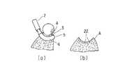
そして、図8(a)に示すように、挿入部2をさらに押し進めて縫合器本体5を生体組織の被縫合部Aに向かって前進させる。図1に破線で示すように、操作部本体1の開閉操作部6を引くと、挿入部2の外筒9が後退してカートリッジ3とアンビル4の基端部が外筒9から突出する。
【0038】
したがって、カートリッジ3は継手10の復元力によって、アンビル4は板ばね15の復元力によって押し広げられ、縫合器本体5が開く。そして、被縫合部Aをカートリッジ3とアンビル4との間に入れ、次に開閉操作部6を図1の実線に示すように押し込むと、外筒9が前進してカートリッジ3とアンビル4の基端部に外筒9が嵌合し、カートリッジ3とアンビル4が閉じて縫合器本体5によって被縫合部Aを挟持する。
【0039】
この状態で、操作部本体1のステープル操作部7を図1の矢印a方向に引くと、挿入部2の内筒8に内挿されたプッシャプレート24とワイヤカッタ20が前進し、プッシャプレート24はプレートガイド溝23に案内されて前進し、ワイヤカッタ20はワイヤガイド溝18,19に案内されて前進する。
【0040】
プッシャプレート24の前進に伴ってカートリッジ3の内部のプッシャ21aは傾斜面24aによって押し上げられ、スリット21の内部のステープル22は突出し、被縫合部Aに打ち出される。打ち出されたステープル22の脚部22aは生体組織を貫通し、その脚部22aはアンビル4に設けられた成形溝25によって互いに内側に折り曲げられ、被縫合部Aをステープル22によって縫合する。
【0041】
このようにステープル22によって被縫合部Aが2列づつ平行に2箇所縫合されると同時にワイヤカッタ20も前進するため、図8(b)に示すように、2箇所の縫合部の間に位置する生体組織はワイヤカッタ20のナイフ部29によって切断される。したがって、縫合と切断が同時に行うことができる。
【0042】
このとき、高周波焼灼装置35から高周波接続ケーブル33を介して高周波接続ピン32に高周波電流が流れ、さらに導電性部材31を介してワイヤカッタ20のナイフ部29に高周波電流が通電されるため、被縫合部Aの縫合時に生体組織を焼灼しながら縫合することができる。また、生体組織の切除を通電止血しながら行うので出血の恐れがないという効果がある。
【0043】
また、縫合器本体5が挿入部2の軸方向に対して略90゜湾曲しているため、被縫合部Aが挿入部2の軸線に対して平行もしくは垂直の方向に無いときに特にアプローチしやすく、また、操作部本体1に対して挿入部2が回転自在であるため、縫合器本体5を任意の方向に向けることができる。
【0044】
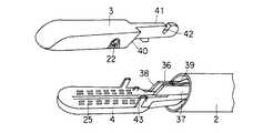
図11〜図14は第2の実施形態を示し、第1の実施形態と同一構成部分は同一番号を付して説明を省略する。この実施形態は縫合器本体5を構成するカートリッジ3を挿入部2に対して着脱自在に構成したものである。すなわち、挿入部2の先端部には2枚の板体を離間して平行に配置したカートリッジ接続部材36が設けられている。このカートリッジ接続部材36の基端部には2枚の板体間に亘ってヒンジピン37が架設され、先端部には傾斜面からなるカム面38が設けられている。さらに、カートリッジ接続部材36の上面には板ばねからなる押え部材39が圧接状態に設けられている。
【0045】
一方、カートリッジ3の基端部には前記カム面38と摺動する傾斜面40および突出片41が設けられている。この突出片40には前記ヒンジピン37に係合するヒンジ溝42が設けられている。
【0046】
そして、カートリッジ3の傾斜面40をカートリッジ接続部材36のカム面38上をスライドしながら突出片41をカートリッジ接続部材36の板体間に挿入することによってヒンジ溝42がヒンジピン37に係合され、カートリッジ3はカートリッジ接続部材36に対して上下方向に回動自在に枢支されている。さらに、カートリッジ3の突出片41は押え部材39によって下方へ弾性的に押圧されている。
【0047】
したがって、カートリッジ3はカートリッジ接続部材36に対して上下方向に移動自在であり、傾斜面40がカム面38を摺動しながら移動する。したがって、カートリッジ3はアンビル4と接離自在であり、生体組織をカートリッジ3とアンビル4とによって挟持する際に、生体組織の肉厚に応じてカートリッジ3が移動して肉厚に対応できる。なお、43はアンビル4に突設されたガイド片であり、カートリッジ3の横方向のずれを防止できる。
【0048】
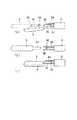
図15〜図17は第3の実施形態を示し、第1の実施形態と同一構成部分は同一番号を付して説明を省略する。この実施形態はステープル22を打ち出すプッシャプレート24の変形例であり、プッシャプレート24の先端部にはその先端から長手方向に沿って割り溝44が設けられている。
【0049】
そして、プッシャプレート24の下部桟44aはプレートガイド面23にスライド自在に接合され、上部桟44bはプッシャ21aに接合されているとともに、下部桟44aとの間に介在された複数個のコイルスプリング45…によって弾性的に上下動自在に支持されている。
【0050】
したがって、プッシャプレート24の前進に伴ってカートリッジ3の内部のプッシャ21aは傾斜面24aによって押し上げられ、スリット21の内部のステープル22は突出し、被縫合部Aに打ち出される。打ち出されたステープル22の脚部22aは生体組織を貫通し、その脚部22aはアンビル4に設けられた成形溝25によって互いに内側に折り曲げられ、被縫合部Aをステープル22によって縫合する。
【0051】
このとき、生体組織のうち、通常組織xの部分は打ち出されたときステープル22の脚部22aが深く折曲されるが、硬い組織yの部分はステープル22が打ち出されるときの反力によってプッシャプレート24のコイルスプリング45…が圧縮されて上部桟44bが下方に湾曲する。したがって、ステープル22が打ち出されたとき、上部桟44bが下方に湾曲した分だけ脚部22aが浅く折曲される。
【0052】
したがって、通常組織xの部分においても、硬い組織yの部分においても適度の力量でステープル22が打ち出されて生体組織を縫合することができ、縫合不全を防止することができる。
【0053】
また、高周波接続ピン32、プッシャプレート24、プッシャ21aを介してステープル22に高周波電流が流せるように構成されており、その他の部分は絶縁材によって形成されている。したがって、ステープル22の周囲の被縫合部Aを凝固焼灼しながら縫合することができる。
【0054】
また、複数のステープル22列のうち、一部の列、好ましくは切除線に近い列に高周波電流を流してもよい。なお、ステープル22は、チタン、ニッケルなどの金属製が導電性樹脂を用いる。
【0055】
図18は第3の実施形態の変形例であり、プッシャプレート24の先端部に斜めにスリット46を設け、プッシャプレート24自体の弾力で変形するようにしたものであり、第3の実施形態と同様の効果がある。
【0056】
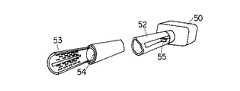
図19〜図21は前記各実施形態とは異なる縫合装置を示すもので、49はトラカール部である。このトラカール部49は、トラカール把持部50と先端に割り溝51を有したトラカール挿入部52およびこのトラカール挿入部52の内部に設けられ先端にアンビル部材53を有している。前記トラカール挿入部52には軸方向に進退自在な挿入される内筒54とこの内筒54の基端部に設けられた摺動操作部55とから構成されている。
【0057】
56は縫合部であり、これは前記トラカール部49の内部に挿入可能な挿入部57とこの挿入部57の先端部にヒンジ58で接続され、内部に組織を縫合するステープル(図示しない)を内蔵し、かつ各々のステープルを突出させる押出し機構(図示しない)を有するカートリッジ部材59を有している。
【0058】
このカートリッジ部材59にはガイド溝59aに案内されて前後方向に進退自在なナイフ部材60と前記挿入部57に接続されている把持部61と前記カートリッジ部材59の内部のステープルを突出させるとともに、ナイフ部材60を摺動させるレバー62が設けられている。
【0059】
このように構成された縫合器によれば、アンビル部材53とカートリッジ部材59との間に生体組織を入れ、摺動把持部55を把持しながらトラカール挿入部52を前方へ移動すると、トラカール挿入部52がアンビル部材53とカートリッジ部材59を覆うことにより、隙間がなくなり、生体組織を両部材によって確実に挟持することができる。
【0060】
この状態で、レバー62を引くことにより、カートリッジ部材59のステープルが突出し、生体組織をステープルによって縫合することができ、同時にナイフ部材60もカートリッジ部材59を摺動して組織を切除することができる。
【0061】
この縫合装置によれば、縫合部56の挿入部57がトラカールの役目をするため、縫合作用のトラカールが不用となり、分細径化が図られ、かつ低侵襲である。また、縫合部56を使用しないときにはトラカール部49は通常のトラカールとして機能するという効果がある。
【0062】
図22および図23は図19〜図21に示した縫合装置の変形例で、縫合部56の先端部に接続されるカートリッジ部材59のヒンジ部63に関するものであり、トラカール挿入部52にはヒンジピン64が突設され、カートリッジ部材59の基端部には傾斜面59aおよびカートリッジ部材59が上下方向に移動自在に前記ヒンジピン64に係合する長穴からなるヒンジ孔65が穿設されている。
【0063】
さらに、トラカール挿入部52および内筒54には軸方向にガイド溝52a,54aが設けられ、前記ヒンジ部63はガイド溝52a,54aから側方へ突出するようになっている。
【0064】
したがって、アンビル部材53とカートリッジ部材59とで形成された組織挟み代66の内部に生体組織を入れ、トラカール挿入部52を前進させると、カートリッジ部材59の傾斜面59aが押圧されてヒンジピン64とヒンジ孔65とが相対的に移動してカートリッジ部材59が上昇し、アンビル部材53とで生体組織を挟持する。
【0065】
このようにアンビル部材53に対してカートリッジ部材59が平行移動してアンビル部材53とで生体組織を挟持するため、生体組織が滑って逃げることはなく、アンビル部材53とカートリッジ部材59の先端側の生体組織も確実に挟持して縫合できるという効果がある。
【0066】
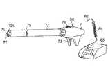
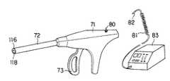
図24〜図30は第4の実施形態を示す。図30は縫合装置の全体構成を示すもので、操作部本体71には縫合器本体としての挿入部72が回転自在に連結されている。操作部本体71にはステープル操作ハンドル73と湾曲操作レバー74が設けられている。
【0067】
挿入部72の先端部72aの近傍には湾曲部75が設けられ、先端部72aの端面には縫合部材としてのステープルを放出するステープル放出部76およびステープル放出部76と近接して突出すように取り付けられた穿刺手段としての針状部材77が設けられている。
【0068】
針状部材77の基端部は先端部72aに対して絶縁体78によって支持されており、この針状部材77は挿入部72に内挿された導電部材79を介して操作部本体71に導かれ、この導電部材79は操作部本体71に設けられた高周波接続ピン80に電気的に接続されている。
【0069】
この高周波接続ピン80には高周波接続ケーブル81の一端部に設けられたコネクタ82が接続され、この高周波接続ケーブル81の他端は高周波焼灼装置83に接続されている。
【0070】
図24〜図27は、挿入部72の先端構造を示すもので、挿入部72の内部における下半分にはステープル収納部としてのステープル収納溝84が設けられている。挿入部72の内部における上半分にはアンビル収納溝85が設けられ、これらは挿入部72の長手方向に沿って設けられている。ステープル収納溝84の内部には弾性を持った金属板体からなるステープルトラック86が収納され、この先端部には傾斜立上り面86aを介してコ字状に折曲されたカム面87が設けられている。
【0071】
前記ステープルトラック86の上部には押えプレート88が設けられ、このステープルトラック86と押えプレート88との間には複数個の縫合部材としてのステープル89…が収納され、このステープル89は細径線材を略ω状に成形したもので、その尖端脚部を先端側に向けて配列され、ステープル収納溝84に設けられた押圧ばね90によってステープル出口91aの方向に付勢されている。
【0072】
前記押えプレート88の上部にはステープル出口91aと連通する成形トラック92aを前後方向に摺動自在な成形部材92が設けられている。この成形部材92は先端部にコ字状の切欠部からなる成形部93が設けられているとともに、上部には突起94が設けられている。この成形部材92は前記操作部本体71に設けられたステープル操作ハンドル73と連結されており、ステープル操作ハンドル73によってステープル出口91aとステープル成形部91bとの間を進退自在になっている。
【0073】
この成形部材92の上部で、前記アンビル収納溝85の内部には前後方向に移動自在なアンビル95が設けられている。このアンビル95には前記突起94と係合するアンビル溝85を有しているとともに、アンビル収納溝85に設けられたアンビル規制溝97に係合する突出片98を有している。
【0074】
さらに、このアンビル95の先端部にはステープル89の変形時にステープル89の中央部に当接するフランジ99が設けられているとともに上面にスリット100が設けられている。このスリット100には線状体からなる解放ばね101が挿入されて下方へ三角形状に突出しており、ステープル89の変形後、ステープル89をアンビル95のフランジ99から放出するように付勢している。
【0075】
また、挿入部72の先端面のステープル放出部76は、ステープル放出口102と、この下方にステープル放出口102と連通するステープル放出溝103が設けられ、このステープル放出溝103は変形後のステープル89が通過するだけの幅を持っている。
【0076】
図28は前記湾曲部75の構造を示すもので、挿入部先端側72xと挿入部末端側72yは回動自在に連結されている。すなわち、挿入部先端側72xは円筒状の先端側カバー104によって覆われ、挿入部末端側72yは円筒状の末端側カバー105によって覆われている。これらカバー104と105はヒンジ部106によって回動自在に枢支されている。
【0077】
末端側カバー105の上部側には前記操作部本体71に設けられた湾曲操作レバー74と連結された湾曲操作ワイヤ107が挿通されており、この湾曲操作ワイヤ107はヒンジ部106を通過して先端側カバー104に連結されている。ヒンジ部106の下部側には先端側カバー104と末端側カバー105との間に介在されたばね部材108が設けられ、湾曲部75をストレートな状態に復帰するように付勢している。
【0078】
さらに、挿入部先端側72xの軸心部には軸方向に貫通孔109が設けられ、この貫通孔109には前記成形部材92の末端部が軸方向にスライド自在に挿入され、この成形部材92はスプリング110によって操作部本体71側へ付勢されている。
【0079】
挿入部末端側72yの軸心部には軸方向に貫通孔111が設けられ、この貫通孔111には操作部本体71のステープル操作ハンドル73と連結された操作ワイヤ112が挿通され、これは前記成形部材92と連結されている。
【0080】
操作ワイヤ112はコイルシース113によって被覆され、さらにその外側が軟性の材質の操作チューブ114によって被覆されている。そして、このコイルシース113および操作チューブ114はヒンジ部106を通過して挿入部先端側72xに連結されている。
【0081】
したがって、操作部本体71の湾曲操作レバー74を手元側へ引くと湾曲操作ワイヤ107が操作部本体71側へ引かれ、先端側カバー104が末端側カバー105とのヒンジ部106を中心として回動して挿入部72の湾曲部75は湾曲する。また湾曲部75は常にストレートの状態になるようにばね部材108により付勢されており、湾曲操作レバー74を解放すると挿入部72はストレートの状態になる。
【0082】
なお、ここで湾曲操作レバー74にロック機構を設けて湾曲をかけた状態を維持できるようにしてもよい。また、湾曲をかけた状態でも、ステープル操作ハンドル73を操作して操作ワイヤ112の力を成形部材92に伝える経路は前述のようにフレキシブルに構成されているので、ステープル89を変形させることができる。
【0083】
次に、前述のように構成された縫合装置の作用について説明する。
【0084】
図24はステープル装填時の状態、図25はステープル変形時の状態を示す。操作部本体71のステープル操作ハンドル73を操作し、操作ワイヤ112を前進させると、この操作ワイヤ112と連結された成形部材92は先端方向へ移動する。ステープル出口91aでは成形部材92はステープルトラック86の先端より押し上げられたステープル89と突き当てられ、ステープル89を先端方向に移動させる。
【0085】
その後、ステープル89は解放ばね101の成形トラック92a内に突出されるように設けられた折曲部101aの後側に突き当てられる。この時、解放ばね101とアルビル95は固定されているので、アンビル95も同時に先端方向への力を受け移動を開始する。
【0086】
ステープル成形部91bにおいてアンビル規制溝97の先端側にアンビル95の上面の突出片98が当接してアンビル95の移動が止まる。さらに、成形部材95とステープル89は先端側へ移動を行う。この時、ステープル89の中央部に突き当てられていた解放ばね101は押しのけられ、ステープル89の中央部はフランジ99と当接する。
【0087】
さらに、成形部材92が先端側へ移動し、ステープル89は成形部材92の成形部93とフランジ99との間で変形されて閉じた状態になる。この時、ステープル操作ハンドル73は完全に閉じた状態になる。その後、ステープル操作ハンドル73を操作して操作ワイヤ112を後退させると、成形部材92は操作部本体71側へ移動し始め、変形後のステープル89を保持していた力がなくなり、解放ばね25による下方へ加えられた力により、閉じられたステープル89はフランジ99によりステープル放出部76を通って挿入部72の先端から放出される。ステープル放出部76には下方に変形後のステープル89が通過する放出溝103があるため、変形後のステープル89はこの放出溝103を通って放出される。
【0088】
ステープル89の変形後、最初に成形部材92が操作部本体71側へ移動し、アンビル溝96の後端部に成形部材92の突起94が突き当てられ、アンビル95も後端側へ移動する。このアンビル95と成形部材92の移動はアンビル95の上面の突出片98がアンビル規制溝97の後端に突き当たる位置で停止する。この時、成形部材92が覆っていたステープル出口91aは開かれステープルトラック86の前端の弾性力により、次のステープル89が成形部材92の先端へ押し上げられる。
【0089】
また、成形トラック92aの先端はステープル出口91aとステープル収納溝84を塞ぎ、次のステープル89がステープル出口91aに移動するのを防ぐ。なお、成形部材92がステープル出口91aの上部を通過する時、成形部材92の下面とステープルトラック86と一体のカム面87が当接し、ステープルトラック86の先端部はステープル収納溝84内に押し戻された次のステープル89がステープルトラック86の先端へ移動してくる。
【0090】
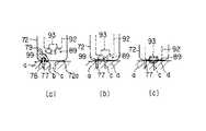
したがって、前述のように構成された縫合装置を用いて生体組織の縫合部位を縫合する場合には、図30の(a)に示すように、ステープル89の変形前に、高周波焼灼装置82から高周波接続ケーブル81を介して高周波接続ピン80に高周波電流が流れ、さらに導電部材79を介して針状部材77に高周波電流が通電される。
【0091】
次に、挿入部72の先端の針状部材77を組織aの縫合部位bの近傍に刺入する。針状部材77を組織aに刺入した後、挿入部72の先端部72aを移動し、同図の(b)に示すように、切開部(傷口)cを閉じるように反対側の組織片へ近付ける。次に、同図の(c)に示すように、組織片同士を密着させたまま、前述した操作によってステープル89を組織aに刺入変形させ、切開部cの縫合を行なう。
【0092】
このように挿入部72の先端に針状部材77を設けることにより、組織aの縫合部位bを確認しやすく、術者は片手操作で簡単に組織片を合わせて縫合を行うことができるとともに、高周波電流によって組織を焼灼することができる。
【0093】
図31〜図38は第5の実施形態を示す。図38は縫合装置の全体構成を示すもので、操作部本体71には縫合器本体としての挿入部72が回転自在に連結されている。操作部本体71にはステープル操作ハンドル73が設けられている。
【0094】
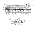
図31〜図33は、挿入部72の先端部に内蔵されたステープル成形機構115を示すもので、挿入部72はステープル放出部116を有する上カバー117とステープル放出溝118を有する下カバー119とから構成されている。
【0095】
下カバー119にはステープル収納部としてのステープル収納溝84が設けられ、上カバー117にはアンビル収納溝85が設けられ、これらは挿入部72の長手方向に沿って設けられている。ステープル収納溝84の内部には弾性を持った金属板体からなるステープルトラック86が収納され、この先端部には傾斜立上り面86aを介してコ字状に折曲されたカム面87が設けられている。
【0096】
前記ステープルトラック86の上部には逆行防止爪88aを有する押えプレート88が設けられ、このステープルトラック86と押えプレート88との間には縫合手段としての複数個のステープル89…が収納されている。このステープル89は細径線材を略ω状に成形したもので、一対の刺入部89a,89bが設けられている。そして、一対の刺入部89a,89bを先端側に向けて配列され、ステープル収納溝84に設けられた押圧ばね90によってステープル出口91aの方向に付勢されている。
【0097】
前記押えプレート88の上部にはステープル出口91aと連通し、前後方向に摺動自在な一対の刺入操作手段としての右押圧部材120aと左押圧部材120bが並設されている。右押圧部材120aの先端には切欠部が設けられ、この切欠部と左押圧部材120bの先端とによってコ字状の成形部93が設けられている。
【0098】
右押圧部材120aの上部には前記逆行防止爪88aと掛合する掛合孔121aと突起121bが設けられている。この右押圧部材120aと左押圧部材120bは前記操作部本体71に設けられた復帰ばね130によって後退方向に付勢されているとともに、後述する手段によってステープル操作ハンドル73と連結されており、ステープル操作ハンドル73によってステープル出口91aとステープル成形部91bとの間を進退自在になっている。
【0099】
この右押圧部材120aの上部で、前記アンビル収納溝85の内部には前後方向に移動自在なアンビル95が設けられている。このアンビル95には前記突起121bと係合するアンビル溝96を有しているとともに、アンビル収納溝85に設けられたアンビル規制溝97に係合する突出片98を有している。
【0100】
さらに、このアンビル95の先端部にはステープル89の変形時にステープル89の中央部に当接する保持部としてのフランジ99が設けられているとともに上面にスリット100が設けられている。このスリット100には線状体からなる解放ばね101が挿入されて下方へ三角形状に突出しており、ステープル89の変形後、ステープル89をアンビル95のフランジ99から放出するように付勢している。
【0101】
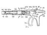
図34〜図36に示すように、操作部本体71にはステープル操作ハンドル73が枢支ピン132を支点として開閉自在に枢支され、スプリング133によって後退方向へ付勢されている。
【0102】
ステープル操作ハンドル73には連結ピン134によって押圧部材135が連結され、この押圧部材135はステープル操作ハンドル73によって前後方向に移動自在に設けられている。押圧部材135の先端には連続的な周状の4つのカム面135aが形成され、このカム面135aは後端に周状の4つのカム面137aを持ち、かつ前後方向に移動自在な同筒状の切替部材137と対向している。
【0103】
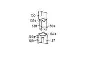
切替部材137は付勢ばね136によって操作部1側に付勢されている。また、切替部材137の外周には操作部本体71に設けられた規制溝138と嵌合し、その後端にカム面139aを有するガイド部139が周方向に4等分に配置されている。切替部材137の前端には外押圧部140と、この外押圧部140より内周側に配置された内押圧部141が90°間隔に交互に配置されている。
【0104】
また、切替部材137と押圧部材135は操作部本体71に設けられ前端両側にカム面138aを持つ規制溝138によって周方向の回転が規制されている。さらに、規制溝138によって支持されているとき、押圧部材135と切替部材137の周状のカム面135a,137aは1/4ピッチずれている。
【0105】
したがって、ステープル操作ハンドル73をスプリング133の付勢力に抗して矢印a方向に回動すると、押圧部材135が前進し、切替部材137を前方へ押す。切替部材137が規制溝138のない位置まで押されると、押圧部材135と切替部材137の接するカム面135a,137aは1/4ピッチずれているため、ずれを補正する方向へ回転するようになっている。
【0106】
ステープル操作ハンドル73が矢印a方向と反対方向に回動すると、切替部材137は付勢ばね136により後方へ付勢され規制溝138の入口で再びガイド部139の端面のカム面139aと規制溝138のカム面138aが当接して回転され、90°の方向にある他のガイド部139が規制溝138に入るようになっている。つまり、ステープル操作ハンドル73の1回の開閉で切替部材137は90°ずつ回転するようになっている。
【0107】
一方、前記右押圧部材120aの後端は挿入部72の長手方向軸に対して外側に、左押圧部材120bの後端は挿入部72の長手方向軸に対して内側に配置されているため、ステープル操作ハンドル73の1回の開閉で切替部材137は90°ずつ回転し、右押圧部材120aと左押圧部材120bには、外押圧部140、内押圧部141とが交互に接するようになる。
【0108】
さらに、右押圧部材120aの先端部には成形部93に露出する電極部材142が絶縁体143を介して固定されており、この電極部材142は挿入部72に内挿された導電部材79を介して操作部本体71に導かれ、この電極部材142は操作部本体71に設けられた高周波接続ピン80に電気的に接続されている。
【0109】
この高周波接続ピン80は高周波接続ケーブル81の一端部に設けられたコネクタ82に接続され、この高周波接続ケーブル81の他端は高周波焼灼装置83に接続されている。
【0110】
次に、前述のように構成された縫合器の作用について説明する。
【0111】
図33はステープル成形前の状態、図32はステープル成形時の状態を示す。操作部本体71のステープル操作ハンドル73を操作し、押圧部材135を介して切替部材137が前進し、外押圧部140によって右押圧部材120aに押圧されると、右押圧部材120aは先端方向へ移動する。
【0112】
ステープル出口91aではステープルトラック86の先端より押し上げられたステープル89が待機しているため、そのステープル89は解放ばね101の折曲部101aの後側に突き当てられる。この時、解放ばね101とアルビル95は固定されているので、アンビル95も同時に先端方向への力を受け移動を開始する。
【0113】
ステープル成形部91bにおいてアンビル規制溝97の先端側にアンビル95の上面の突出片98が当接してアンビル95の移動が止まる。さらに、右押圧部材120aとステープル89は先端側へ移動を行う。この時、ステープル89の中央部に突き当てられていた解放ばね101は押しのけられ、ステープル89の中央部はフランジ99と当接する。
【0114】
さらに、右押圧部材120aが先端側へ移動し、ステープル89の右刺入部89aは右押圧部材120aとフランジ99との間で変形される。ステープル操作ハンドル73からの力がなくなると、右押圧部材120aは復帰ばね130によって後方へ移動しようとするが、押えプレート88に設けられた逆行防止爪88aにより成形位置で固定される。
【0115】
さらに、ステープル操作ハンドル73を矢印a方向に回動すると、切替部材137が90°ずつ回転し、内押圧部141が左押圧部材120bに接し、左押圧部材120bに力が加わり、左押圧部材120bが先端側へ移動し、ステープル89の左刺入部89bが変形される。
【0116】
成形中において、左押圧部材120bの下面で逆行防止爪88aを押さえ、右押圧部材120aの固定を解除する。ステープル操作ハンドル73が戻り始めると左押圧部材120bに加わる先端方向への力はなくなり、解放ばね101により変形後のステープル89は下側に押され、ステープル放出溝118を通って放出される。また左右押圧部材120a,120bは後方へ戻り初期状態になる。
【0117】
ステープル89の成形後、左右押圧部材120a,120bが復帰ばね130によって操作部本体71側へ移動し、アンビル溝96の後端部に右押圧部材120aの突起121bが突き当てられ、アンビル96も後端側へ移動する。このアンビル95と右押圧部材120aの移動はアンビル95の上面の突出片98がアンビル規制溝97の後端に突き当たる位置で停止する。この時、左右押圧部材120a,120bが覆っていたステープル出口91aは開かれステープルトラック86の前端の弾性力により、次のステープル89が左右押圧部材120a,120bの先端へ押し上げられる。
【0118】
したがって、前述のように構成された縫合装置を用いて生体組織の縫合部位を縫合する場合には、図37の(a)に示すように、ステープル放出部116を縫合部位に位置決めし、同図(b)に示すように、右押圧部材120aによってステープル89の右刺入部89aを変形する。ステープル89の右刺入部89aを成形させた状態、つまりステープル89の成形過程で、その一端を挿入部72の先端から突き出させることで一方の組織片xに右刺入部89aを刺入することができる。次に、挿入部72の先端部を移動させ、組織片xを他方の組織片yに引き寄せることができる。次に、同図(c)に示すように左押圧部材120bによってステープル89の左刺入部89bを変形することにより、組織片yを組織片xに引き寄せ、組織片x,y同士を密着した状態で縫合することができる。したがって、縫合部位を合わせるために把持鉗子を必要とせず、縫合操作が簡単になり、処理部位の視認性もよくなる。
【0119】
このとき、高周波焼灼装置83から高周波接続ケーブル81を介して高周波接続ピン80に高周波電流が流れ、さらに導電部材79を介して電極部材142に高周波電流が通電されるため、ステープル89を介して縫合部位の生体組織を焼灼しながら縫合することができる。
【0120】
図39〜図41は第6の実施形態を示し、体腔内の管状組織の端部を縫合する縫合装置あり、操作部本体151と挿入部152とからなり、操作部本体151にはハンドル153、厚み調節ねじ154および高周波接続ピン155が設けられている。挿入部152の先端には内部に縫合部材としてのU字状のステープル156を円筒状に複数個収容するステープル収容部157が設けられている。
【0121】
ステープル収容部157の中心部にはアンビル軸158が貫通して設けられ、この先端部にはねじ軸からなる連結部159が突設され、この接続部159はアンビル160の連結ロッド161に設けられたねじ穴162に着脱可能に接続されるようになっている。さらに、連結部159はアンビル軸158に内挿された通電ケーブル163を介して前記高周波接続ピン155に電気的に接続されている。
【0122】
ステープル収容部157の内部にはステープル156を後方から前方へ押し出すためのプッシャ164が進退自在に設けられ、このプッシャ164は挿入部152に内挿された連結管165を介してハンドル153に連結されている。さらに、前記ステープル156列の内周には円筒状のカッタ166が進退自在に設けられている。
【0123】
前記高周波接続ピン155は高周波接続ケーブル167の一端部に設けられたコネクタ168に接続され、この高周波接続ケーブル167の他端は高周波焼灼装置169に接続されている。
【0124】
したがって、アンビル160とステープル収容部157との間に縫合する一方の組織eを位置し、連結部159に高周波電流を流しながら連結部159を組織eに穿刺する。連結部159が組織eを突き抜けた後、他方の組織fに位置させたアンビル160の連結ロッド161のねじ穴162に連結部159を接続する。
【0125】
アンビル160とステープル収容部157との間を適切な距離に調節し、ハンドル153を閉じると、プッシャ164が前進してステープル収容部157の内部のステープル156が組織e,fに穿刺されるとともに、アンビル160によってU字状のステープル156の脚部が内側に変形され、組織e,fを縫合する。同時にカッタ166が前進して縫合部より内側の組織e,fを切除することができる。
【0126】
このように連結部159に高周波電流を流しながら連結部159を組織eに穿刺することにより、穿刺するときの抵抗が小さくなり、また穿刺部位に血管があり、出血しやすい場合でも高周波電流により焼灼止血できる。また、連結部159の先端に鋭利な針部を取り付ける必要がなく、操作性が向上するという効果がある。
【0127】
図42および図43は第7の実施形態を示し、図42は縫合装置としてのクリップアプリケータの全体を示す。クリップ装置171には複数のU字状のクリップ172を収容するクリップ収容部(図示しない)が設けられている。クリップ装置171は操作部本体173と挿入部174とからなり、操作部本体173にはハンドル175、スイッチ176および高周波接続ピン177が設けられ、この高周波接続ピン177は高周波接続ケーブル178を介して高周波焼灼装置(図示しない)に電気的に接続されている。
【0128】
挿入部174の先端部にはジョー179が設けられ、このジョー179はハンドル175によって開閉され、ハンドル175を操作してジョー179を閉じたときにあらかじめ装填されているクリップ172を変形され、血管等を結紮して留置できるようになっている。
【0129】
操作部本体173、挿入部174、ハンドル175はプラスチック材料等の絶縁材料によって形成され、ジョー179はステンレス材料等の導電材料によって形成されている。但し、図43に示すように、ジョー179は、その内面、つまりクリップ172と接触する部分を除き、テフロンコーティング、セラミックコーティング、塗料等の絶縁膜180が施されている。
【0130】
このクリップアプリケータの作用を説明すると、結紮しようとする血管をジョー179に装填されたクリップ172の間に位置させた後、ハンドル175を操作してジョー179を閉じ、クリップ172を塑性変形させて血管に結紮留置させ、この状態でスイッチ176を操作してジョー179を介してクリップ172に高周波電流を流して焼灼する。血管の複数箇所を前記操作によって結紮留置した後、クリップ172相互間の血管を切断する。
【0131】
このようにクリップ172の塑性変形による機械的な血流の遮断に加えて高周波電流の焼灼による止血も付加されるため、クリップ172を留置した部分から出血することがなく安全である。また、他の手術操作により不用意にクリップ172が移動、脱落のあった場合にも出血することがなく、安全性が極めて高い。
【0132】
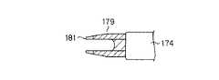
図44は第7の実施形態の変形例1を示し、ジョー179の先端部に非絶縁部181を設けたものである。なお、非絶縁部181はモノポーラだけでなく、バイポーラとなるように構成してもよい。
【0133】
このように構成することにより、クリップ172の留置作業を行おうとしてクリップ装置171を体腔内に挿入中に、不意の出血が発生した場合、その出血部位に非絶縁部181を接触させ、スイッチ176を操作することにより、出血部位に高周波電流を流して焼灼を行い止血することができる。また、止血のみに止まらず、組織の剥離作業に用いてもよい。
【0134】
したがって、不意の出血に対してクリップ装置171を抜去して他の高周波用鉗子を挿入する必要がなく、速やかな止血が行え、また高周波用鉗子の抜き挿しの煩わしさがなく、円滑な手術が行える。
【0135】
図45は第7の実施形態の変形例2を示し、ジョー179の内部に一対のクリップ172を装填でき、またジョー179の先端部に絶縁体182を介して一対の電極183を設けた構成である。
【0136】
このクリップアプリケータの作用を説明すると、結紮しようとする血管をジョー179に装填されたクリップ172の間に位置させた後、ハンドル175を操作してジョー179を閉じ、クリップ172を塑性変形させて血管に結紮留置させ、この状態でスイッチ176を操作してジョー179を介してクリップ172に高周波電流を流して血管を切断する。
【0137】
このように構成することにより、一回の操作で一対のクリップ172を留置でき、また切断もできる。さらに、高周波電流によって切断するため、止血効果があり、仮にクリップ172の締めが緩い場合にも止血することがなく安全である。高周波電流の強さを調節してクリップ172の間を切断せずに焼灼のみを行ってもよく、この場合、確実な止血法となる。
【0138】
図46および図47は第7の実施形態の変形例3を示し、ジョー179の内部には一対のクリップ172が装填でき、またジョー179の先端部には絶縁体182を介して一対の電極183が進退自在に設けられている。この一対の電極183は挿入部174の内部を貫通する伝達部材(図示しない)を介して操作部本体173に設けられた切断用ハンドル184に連動している。
【0139】
したがって、結紮しようとする血管をジョー179に装填されたクリップ172の間に位置させた後、ハンドル175を操作してジョー179を閉じ、クリップ172を塑性変形させて血管に結紮留置させ、この状態でスイッチ176を操作してジョー179を介してクリップ172に高周波電流を流しつつ、切断用ハンドル184を操作すると、一対の電極183が進退(図48において紙面に対して垂直方向)して血管を切断できる。一対の電極183は先端が鋭角に形成されているため、血管との接触面積が小さく、切れ味が良好である。
【0140】
なお、前記各実施形態においては、挿入部の先端部に縫合部材を設け、経皮的に体腔内に挿入して体腔内組織を縫合する場合について説明したが、一般の外科手術にも利用できる。
【0141】
【発明の効果】
以上説明したように、この発明によれば、挿入部の先端部に一対の刺入部を有する縫合手段を設けることにより、挿入部を体腔内に挿入し、その先端部の縫合手段を被縫合部に位置決めし、縫合する際に、縫合手段の一対の刺入部を被縫合部の組織に独立して刺入して組織同士を引き寄せた状態で被縫合部を縫合することができる。従って、組織の切開部等を密着した状態で効率的に縫合でき、手術時間を短縮することができるという効果がある。
【図面の簡単な説明】
【図1】この発明の第1の実施形態を示す縫合装置の全体の斜視図。
【図2】同実施形態の縫合器本体の分解斜視図。
【図3】同実施形態の縫合器本体の斜視図。
【図4】同実施形態の挿入部の先端部の縦断側面図。
【図5】同実施形態の挿入部の先端部の縦断側面図。
【図6】同実施形態の挿入部の横断正面図。
【図7】同実施形態の縫合器本体の縦断側面図。
【図8】同実施形態の縫合装置の使用状態の斜視図。
【図9】同実施形態の縫合装置の全体の斜視図。
【図10】同実施形態の操作部本体の一部切欠した斜視図。
【図11】この発明の第2の実施形態を示す縫合装置の縫合部材の分解斜視図。
【図12】同実施形態の縫合器本体の斜視図。
【図13】同実施形態の縫合装置の全体の斜視図。
【図14】同実施形態の縫合器本体の組立て手順を示す説明図。
【図15】この発明の第3の実施形態を示す縫合器本体の側面図。
【図16】同実施形態の作用説明図。
【図17】同実施形態の縫合装置で縫合された生体組織の状態を示す断面図。
【図18】同実施形態の縫合器本体の変形例を示す側面図。
【図19】この発明の第1〜第3の実施形態とは異なる縫合装置の全体の斜視図。
【図20】同縫合装置のトラカール部材の斜視図。
【図21】同縫合装置の縫合部の斜視図。
【図22】図19の縫合装置の変形例を示すアンビル部材とカートリッジ部材の縦断側面図。
【図23】同縫合装置の作用を示す説明図。
【図24】この発明の第4の実施形態の縫合装置のステープル装填時の挿入部を示す縦断側面図。
【図25】同実施形態の縫合装置のステープル変形時の挿入部を示す縦断側面図。
【図26】同実施形態の挿入部の正面図。
【図27】同実施形態の挿入部の分解斜視図。
【図28】同実施形態の挿入部の湾曲部の縦断側面図。
【図29】同実施形態の縫合装置の全体を示す斜視図。
【図30】同実施形態の作用説明図。
【図31】この発明の第5の実施形態の縫合装置の挿入部の分解斜視図。
【図32】同実施形態の縫合装置のステープル成形時の挿入部を示す縦断側面図および正面図。
【図33】同実施形態の縫合装置のステープル成形前の挿入部を示す縦断側面図。
【図34】同実施形態の縫合装置の縦断側面図。
【図35】同実施形態の押圧部材と切替部材の斜視図。
【図36】図34の矢印a−a線に沿う断面図。
【図37】同実施形態の作用説明図。
【図38】同実施形態の縫合装置全体の斜視図。
【図39】この発明の第6の実施形態の縫合装置全体の側面図。
【図40】同実施形態の縫合装置の挿入部の縦断側面図。
【図41】同実施形態の作用説明図。
【図42】この発明の第7の実施形態のクリップアプリケータ全体の側面図。
【図43】同実施形態のジョーの斜視図。
【図44】この発明の第7の実施形態の変形例1のジョーの平面図。
【図45】第7の実施形態の変形例2のジョーの先端部の正面図。
【図46】第7の実施形態の変形例3のクリップアプリケータ全体の側面図。
【図47】同変形例のジョーの先端部の正面図。
【符号の説明】
72…挿入部
89…ステープル(縫合手段)
89a,89b…刺入部
120a,120b…押圧部材[0001]
BACKGROUND OF THE INVENTION
The present invention relates to a suturing device that penetrates an abdominal wall or the like and inserts it into a body cavity to suture a living tissue in the body cavity.
[0002]
[Prior art]
For example, when performing gallbladder removal surgery to prevent recurrence in gallbladder stone surgery, etc., the connection between the bile duct and gallbladder is cut, but the gallbladder artery and gallbladder vein pass through this connection. It is necessary to sew the part simultaneously with cutting with a knife or the like.
[0003]
In such gallbladder stone surgery and the like, a suturing device that penetrates the abdominal wall and the like and inserts it into a body cavity and sutures the tissue in the body cavity is used. This type of suturing device is conventionally known, for example, in Japanese Utility Model Publication No. 38-19282, Japanese Utility Model Publication No. 60-41924 and Japanese Patent Application Laid-Open No. 3-12126.
[0004]
Japanese Utility Model Publication No. 38-19282 is a suturing device used for surgically suturing the stomach, comprising a staple as a suturing member, a staple gripping member having a staple pushing mechanism, and an anvil member, both of which have the shape of the stomach. And is connected to the anvil member in a freely openable and closable manner by a hinge pin at the end of the staple gripping member.
[0005]
Japanese Utility Model Publication No. 60-41924 is a suturing device for surgically suturing a cancer nucleus, and is a saddle-shaped ligature body, which is formed sufficiently long with one of the fulcrum sandwiched in the body and the other as a handle. The abdomen faces in a bowl-like shape, the staple is held on one side, the other is made of an anvil, and the holding part is curved in accordance with the affected part, and is opened and closed by opening and closing the handle.
[0006]
Japanese Patent Application Laid-Open No. 3-12126 is a suture device that is percutaneously inserted into a body cavity and sutures tissue in the body cavity, and is provided at the insertion portion and the distal end portion of the insertion portion so that it can be freely opened and closed. Is constituted by a suturing device main body comprising a cartridge for holding staples, a filing lever provided at the distal end of the insertion portion for ejecting staples from the cartridge, and a suturing opening / closing lever for opening and closing the suturing device main body.
[0007]
[Problems to be solved by the invention]
Incidentally, Japanese Utility Model Publication No. 38-19282 is composed of only an anvil and a staple holding member and does not have an insertion portion, and therefore cannot be inserted into a body cavity percutaneously. In addition, since there is no cutting means for cutting the tissue in the main body of the suture instrument, a cutting device must be prepared separately when cutting the tissue.
[0008]
In Japanese Utility Model Publication No. 60-41924, when a percutaneous insertion into a body cavity is used, the body cavity wall (abdominal wall, chest wall, etc.) must be incised so that the handle for opening and closing the suture instrument body can be opened and closed. Therefore, since the invasion is large and there is no cutting means, a cutting device must be prepared separately.
[0009]
In Japanese Patent Application Laid-Open No. 3-12126, the suture instrument body is formed straight with respect to the central axis of the insertion portion. Therefore, when there is an adhesion part in the body cavity and the space between the spaces is narrow, it is difficult to approach the main body of the suture device, and when there is no tissue suture portion in the axial direction of the insertion portion, the tissue is inserted into the main body of the suture device with a separate grasping forceps or the like. You have to hold it.
[0010]
As described above, all of the conventional suturing devices have poor operability, and there is a problem that a separate treatment tool is required, the operation time is long, and the burden on the patient is large. In addition, none of the instruments can efficiently stop the flow of blood or body fluid after the periphery of the suture member or tissue is excised.
[0011]
This is because it is difficult to make the arrangement of the suture members completely free, and for those using a single metal suture member such as a hemostatic clip or staple, hemostasis and suture cannot be sufficiently performed due to elastic return after deformation. It was.
[0012]
In addition to tissue sutures, when bleeding occurs, the bleeding part is generally coagulated and stopped with an electric knife, etc., but in endoscopic surgery, a treatment tool is used for this purpose. It was complicated to replace the electrode with an electrode for an electric knife.
[0013]
Furthermore, when the tissue suture site is an incision (wound) and this incision is sutured with staples, it is necessary to suture the incision with the incision closed, but with conventional suture instruments, the incision is closed. It was difficult, and a separate treatment tool such as a grasping forceps was required, and the operation time was long, so that the suturing operation could not be performed efficiently.
[0014]
The present invention has been made paying attention to the above-mentioned circumstances, and the object thereof is to improve efficiency in a state in which an incision portion or the like of a tissue is drawn by a suturing means having a pair of insertion portions that can be inserted into a living tissue. It is an object of the present invention to provide a suturing device that can be sutured automatically and can shorten the operation time.
[0015]
[Means for Solving the Problems]
In order to achieve the above object, the present invention provides an insertion portion that can be inserted into a body cavity, an operation portion provided at a proximal end portion of the insertion portion, a distal end portion provided at the insertion portion, and the distal end portion A pair of insertion parts that can be inserted into the sutured part of a living tissueOn both ends A staple capable of suturing the living tissue;A holding portion that is provided at a distal end portion of the insertion portion and holds a central portion of the staple; In conjunction with the operation of the operation unitOperated off Replacement parts and frontDeadline In conjunction with the replacement member, the pair of staple insertion portionsAlternately left and right Operate and puncture the living tissue alternately into the living tissueRight pressing member and left pressing member Said stapleIn the state where the central part of the In a state in which one puncturing portion is punctured into the sutured portion of the biological tissue and the tissues are pulled together, the other puncture portion of the staple is punctured to sew the sutured portion of the biological tissue. In the suturing device.
SaidThe right pressing member and the left pressing member are preferably operated alternately by the operation of the operation handle provided in the operation unit being linked via the switching member. It is characterized by that.
[0018]
[Action]
Inserting the insertion portion into the body cavity, positioning the suture means at the distal end of the insertion portion to the sutured portion, and inserting the pair of insertion portions of the suture means independently into the tissue of the sutured portion when sewing Thus, the sutured portion can be sutured while the tissues are pulled together.
[0019]
DETAILED DESCRIPTION OF THE INVENTION
Embodiments of the present invention will be described below with reference to the drawings.
[0020]
1 to 10 show the first embodiment, and FIG. 1 shows the overall configuration of the suturing apparatus.
[0021]
The operation portion
[0022]
As shown in FIGS. 2-7, the said
[0023]
Furthermore, an
[0024]
On the other hand, an L-shaped
[0025]
Further, an engagement
[0026]
Therefore, the
[0027]
Further, the suturing device
[0028]
A plurality of
[0029]
Formed on the inner surface of the
[0030]
The
[0031]
An energizing cable 28 a is inserted inside the
[0032]
Further, a
[0033]
The
[0034]
Further, the opening / closing operation unit 6 provided in the operation unit
[0035]
Further, as shown in FIGS. 9 and 10, the energizing cable 28 a connected to the
[0036]
Next, the operation of the suturing device configured as described above will be described. A part of the living body, such as the abdominal wall, is incised, the suturing device
[0037]
And as shown to Fig.8 (a), the
[0038]
Therefore, the
[0039]
In this state, when the
[0040]
As the
[0041]
In this way, the stitched portion A is stitched in parallel by two rows in two rows by the staple 22 at the same time, and the
[0042]
At this time, a high-frequency current flows from the high-
[0043]
Further, since the
[0044]
FIGS. 11-14 shows 2nd Embodiment, and the same component as 1st Embodiment attaches | subjects the same number, and abbreviate | omits description. In this embodiment, the
[0045]
On the other hand, an
[0046]
The
[0047]
Therefore, the
[0048]
15 to 17 show a third embodiment, and the same components as those of the first embodiment are denoted by the same reference numerals and description thereof is omitted. This embodiment is a modification of the
[0049]
The lower beam 44a of the
[0050]
Therefore, as the
[0051]
At this time, the leg portion 22a of the staple 22 is bent deeply when the portion of the normal tissue x is punched out of the living tissue, while the portion of the hard tissue y is pushed by the reaction force when the staple 22 is punched out. The 24
[0052]
Accordingly, the staple 22 can be driven out with an appropriate amount of force in both the normal tissue x portion and the hard tissue y portion, so that the living tissue can be sutured, and the failure of the suture can be prevented.
[0053]
In addition, a high-frequency current is allowed to flow through the staple 22 via the high-
[0054]
In addition, a high-frequency current may be passed through some of the plurality of 22 rows of staples, preferably a row close to the resection line. The staple 22 is made of a metal such as titanium or nickel and uses a conductive resin.
[0055]
FIG. 18 shows a modified example of the third embodiment, in which a
[0056]
19 to 21 show a suturing device different from the above embodiments, and 49 is a trocar portion. The
[0057]
[0058]
The
[0059]
According to the suturing device thus configured, when a living tissue is inserted between the
[0060]
By pulling the
[0061]
According to this suturing device, since the
[0062]
FIGS. 22 and 23 are modifications of the suturing apparatus shown in FIGS. 19 to 21 and relate to the
[0063]
Further, the
[0064]
Accordingly, when a living tissue is put into the
[0065]
In this way, the
[0066]
24 to 30 show a fourth embodiment. FIG. 30 shows the overall configuration of the suturing apparatus, and an operation portion
[0067]
A bending
[0068]
The proximal end portion of the needle-shaped
[0069]
The high
[0070]
24 to 27 show the distal end structure of the
[0071]
A
[0072]
Formed on the upper part of the
[0073]
An
[0074]
Further, a
[0075]
Further, the
[0076]
FIG. 28 shows the structure of the bending
[0077]
A bending
[0078]
Further, a through
[0079]
A through hole 111 is provided in the axial direction at the axial center of the insertion portion
[0080]
The
[0081]
Therefore, when the bending
[0082]
Here, a lock mechanism may be provided on the bending
[0083]
Next, the operation of the suturing device configured as described above will be described.
[0084]
FIG. 24 shows a state when staples are loaded, and FIG. 25 shows a state when staples are deformed. When the staple operation handle 73 of the operation section
[0085]
Thereafter, the
[0086]
In the
[0087]
Further, the forming
[0088]
After the deformation of the staple 89, the forming
[0089]
The leading end of the forming
[0090]
Therefore, when a suture site of a living tissue is sutured using the suturing device configured as described above, the high
[0091]
Next, the needle-
[0092]
By providing the needle-
[0093]
31 to 38 show a fifth embodiment. FIG. 38 shows the overall configuration of the suturing apparatus, and an operating portion
[0094]
FIGS. 31 to 33 show the
[0095]
The
[0096]
A
[0097]
On the upper part of the
[0098]
A hooking
[0099]
An
[0100]
Further, the tip of the
[0101]
As shown in FIGS. 34 to 36, a staple operation handle 73 is pivotally supported on the operation portion
[0102]
A
[0103]
The switching
[0104]
In addition, the switching
[0105]
Accordingly, when the staple operation handle 73 is rotated in the direction of arrow a against the urging force of the
[0106]
When the staple operation handle 73 rotates in the direction opposite to the arrow a direction, the switching
[0107]
Meanwhile, the rear end of the
[0108]
Further, an
[0109]
The high
[0110]
Next, the operation of the suturing device configured as described above will be described.
[0111]
FIG. 33 shows a state before staple forming, and FIG. 32 shows a state during staple forming. When the staple operating handle 73 of the operating portion
[0112]
Since the staple 89 pushed up from the leading end of the
[0113]
In the
[0114]
Further, the
[0115]
Further, when the staple operation handle 73 is rotated in the direction of arrow a, the switching
[0116]
During molding, the
[0117]
After forming the staple 89, the left and right pressing
[0118]
Therefore, when the sutured portion of the living tissue is sutured using the suturing device configured as described above, the
[0119]
At this time, a high-frequency current flows from the high-
[0120]
39 to 41 show a sixth embodiment, which is a suturing device for suturing an end portion of a tubular tissue in a body cavity, and includes an operation portion
[0121]
An
[0122]
A
[0123]
The high
[0124]
Therefore, one tissue e to be sutured is positioned between the
[0125]
When the distance between the
[0126]
In this way, by puncturing the tissue e while passing a high-frequency current through the connecting
[0127]
42 and 43 show a seventh embodiment, and FIG. 42 shows an entire clip applicator as a suturing device. The
[0128]
A
[0129]
The operation portion
[0130]
The operation of the clip applicator will be described. After the blood vessel to be ligated is positioned between the
[0131]
Thus, in addition to mechanical blood flow interruption due to plastic deformation of the
[0132]
FIG. 44 shows a first modification of the seventh embodiment, in which a
[0133]
With this configuration, when an unexpected bleeding occurs during insertion of the
[0134]
Therefore, it is not necessary to remove the
[0135]
FIG. 45 shows a second modification of the seventh embodiment, in which a pair of
[0136]
The operation of the clip applicator will be described. After the blood vessel to be ligated is positioned between the
[0137]
By comprising in this way, a pair of
[0138]
46 and 47 show a third modification of the seventh embodiment. A pair of
[0139]
Therefore, after the blood vessel to be ligated is positioned between the
[0140]
In each of the embodiments described above, the case where the suture member is provided at the distal end of the insertion portion and the tissue in the body cavity is sutured by percutaneously inserted into the body cavity has been described, but it can also be used for general surgery. .
[0141]
【The invention's effect】
As described above, according to the present invention, by providing a suturing means having a pair of insertion portions at the distal end portion of the insertion portion, the insertion portion is inserted into the body cavity, and the suturing means at the distal end portion is sutured. When positioning and suturing, the pair of piercing portions of the suturing means can be inserted independently into the tissue of the sutured portion and the sutured portion can be sutured in a state where the tissues are pulled together. Therefore, there is an effect that the suture can be efficiently sutured in a state where the incision portion of the tissue is in close contact, and the operation time can be shortened.
[Brief description of the drawings]
FIG. 1 is an overall perspective view of a suturing device showing a first embodiment of the present invention.
FIG. 2 is an exploded perspective view of the suturing device main body according to the embodiment.
FIG. 3 is a perspective view of the suturing device main body according to the embodiment.
FIG. 4 is a longitudinal side view of a distal end portion of an insertion portion according to the embodiment.
FIG. 5 is a longitudinal side view of the distal end portion of the insertion portion of the embodiment.
FIG. 6 is a cross-sectional front view of the insertion portion of the embodiment.
FIG. 7 is a longitudinal side view of the suturing device main body according to the embodiment.
FIG. 8 is a perspective view of the suture device of the embodiment in use.
FIG. 9 is an overall perspective view of the suturing device according to the embodiment.
FIG. 10 is a partially cutaway perspective view of the operation unit main body according to the embodiment.
FIG. 11 is an exploded perspective view of a suturing member of a suturing device showing a second embodiment of the present invention.
FIG. 12 is a perspective view of the suturing device main body according to the embodiment.
FIG. 13 is an overall perspective view of the suturing device according to the embodiment.
FIG. 14 is an explanatory view showing an assembly procedure of the suturing device main body according to the embodiment.
FIG. 15 is a side view of a suture instrument body showing a third embodiment of the present invention.
FIG. 16 is an operation explanatory diagram of the embodiment.
FIG. 17 is a cross-sectional view showing a state of a living tissue sutured by the suturing device of the embodiment.
18 is a side view showing a modification of the suturing device main body according to the embodiment. FIG.
FIG. 19 is an overall perspective view of a suturing apparatus different from the first to third embodiments of the present invention.
FIG. 20 is a perspective view of a trocar member of the suturing device.
FIG. 21 is a perspective view of a suturing portion of the suturing device.
22 is a longitudinal side view of an anvil member and a cartridge member showing a modification of the suturing device of FIG. 19. FIG.
FIG. 23 is an explanatory view showing the operation of the suturing device.
FIG. 24 is a longitudinal side view showing an insertion portion when a staple is loaded in a suturing device according to a fourth embodiment of the present invention.
FIG. 25 is a longitudinal side view showing an insertion portion when the staple is deformed in the suturing device of the embodiment.
FIG. 26 is a front view of the insertion portion of the embodiment.
FIG. 27 is an exploded perspective view of the insertion portion of the embodiment.
FIG. 28 is a longitudinal side view of the bending portion of the insertion portion of the embodiment.
FIG. 29 is a perspective view showing the entirety of the suturing device according to the embodiment;
FIG. 30 is an operation explanatory diagram of the embodiment.
FIG. 31 is an exploded perspective view of an insertion portion of a suturing device according to a fifth embodiment of the present invention.
FIG. 32 is a longitudinal side view and a front view showing an insertion portion at the time of staple forming of the suturing device of the embodiment.
FIG. 33 is a longitudinal side view showing an insertion part before staple forming of the suturing device of the embodiment.
FIG. 34 is a longitudinal side view of the suturing device according to the embodiment.
FIG. 35 is a perspective view of a pressing member and a switching member according to the embodiment.
36 is a sectional view taken along the line aa in FIG. 34. FIG.
FIG. 37 is an operation explanatory diagram of the embodiment.
38 is a perspective view of the entire suturing device according to the embodiment. FIG.
FIG. 39 is a side view of the entire suturing device according to the sixth embodiment of the present invention.
40 is a longitudinal side view of the insertion portion of the suturing device of the embodiment. FIG.
41 is an operation explanatory diagram of the embodiment. FIG.
FIG. 42 is a side view of the entire clip applicator according to the seventh embodiment of the present invention.
FIG. 43 is a perspective view of the jaw of the embodiment.
FIG. 44 is a plan view of a jaw of
FIG. 45 is a front view of a tip portion of a jaw according to
FIG. 46 is a side view of the entire clip applicator of
47 is a front view of the tip portion of the jaw according to the modification. FIG.
[Explanation of symbols]
72. Insertion part
89 ... Staple (Suture means)
89a, 89b ... insertion part
120a, 120b ... pressing member
Claims (2)
Translated fromJapanese前記挿入部の基端部に設けられた操作部と、
前記挿入部に設けられた先端部と、
前記先端部に設けられ生体組織の被縫合部に刺入可能な一対の刺入部を両端部に有し、前記生体組織を縫合可能なステープルと、
前記挿入部の先端部に設けられ、前記ステープルの中央部を保持する保持部と、
前記操作部の操作に連動して操作される切替部材と、
前記切替部材に連動して前記ステープルの一対の刺入部を左右交互に操作し、前記刺入部を前記生体組織に交互に穿刺する右押圧部材及び左押圧部材とからなり、
前記ステープルの中央部を前記保持部によって保持した状態で、一方の刺入部を前記生体組織の被縫合部に穿刺して組織同士を引き寄せた状態で、前記ステープルの他方の刺入部を穿刺して前記生体組織の被縫合部を縫合することを特徴とする縫合装置。An insertion part that can be inserted into a body cavity;
An operation portion provided at a proximal end portion of the insertion portion;
A tip provided in the insertion portion;
A staple that is provided at the distal end and can be inserted into a sutured portion of a living tissueat both ends, and a staple that can suture the living tissue;
A holding portion that is provided at a distal end portion of the insertion portion and holds a central portion of the staple;
AndSWITCHING member operated in conjunction with operation of the operating unit,
Operating a pair of penetration of the staple in conjunction with the priorSL SWITCHING memberalternately left and right, it the deployed section from theright pressing member and the left pressing member to puncture alternately to the body tissue,
Withthe central portion of the stapleheld by the holding portion, the other insertion portion of the staple is punctured with one insertion portion inserted into the sutured portion of the living tissue and the tissues pulled together. Then, a suturing device for suturing the sutured portion of the living tissue.
Priority Applications (1)
| Application Number | Priority Date | Filing Date | Title |
|---|---|---|---|
| JP2002191111AJP3867023B2 (en) | 1992-05-19 | 2002-06-28 | Suture device |
Applications Claiming Priority (3)
| Application Number | Priority Date | Filing Date | Title |
|---|---|---|---|
| JP4-126246 | 1992-05-19 | ||
| JP12624692 | 1992-05-19 | ||
| JP2002191111AJP3867023B2 (en) | 1992-05-19 | 2002-06-28 | Suture device |
Related Parent Applications (1)
| Application Number | Title | Priority Date | Filing Date |
|---|---|---|---|
| JP5072553ADivisionJPH0630944A (en) | 1992-05-19 | 1993-03-30 | Suturing apparatus |
Publications (2)
| Publication Number | Publication Date |
|---|---|
| JP2003052704A JP2003052704A (en) | 2003-02-25 |
| JP3867023B2true JP3867023B2 (en) | 2007-01-10 |
Family
ID=26462465
Family Applications (1)
| Application Number | Title | Priority Date | Filing Date |
|---|---|---|---|
| JP2002191111AExpired - Fee RelatedJP3867023B2 (en) | 1992-05-19 | 2002-06-28 | Suture device |
Country Status (1)
| Country | Link |
|---|---|
| JP (1) | JP3867023B2 (en) |
Families Citing this family (11)
| Publication number | Priority date | Publication date | Assignee | Title |
|---|---|---|---|---|
| WO2006044799A2 (en)* | 2004-10-18 | 2006-04-27 | Tyco Healthcare Group, Lp | Extraluminal sealant applicator and method |
| US7467740B2 (en)* | 2005-09-21 | 2008-12-23 | Ethicon Endo-Surgery, Inc. | Surgical stapling instruments having flexible channel and anvil features for adjustable staple heights |
| US7506791B2 (en)* | 2006-09-29 | 2009-03-24 | Ethicon Endo-Surgery, Inc. | Surgical stapling instrument with mechanical mechanism for limiting maximum tissue compression |
| US20080169328A1 (en)* | 2007-01-11 | 2008-07-17 | Shelton Frederick E | Buttress material for use with a surgical stapler |
| JP4503038B2 (en)* | 2007-04-02 | 2010-07-14 | Hoya株式会社 | Endoscopic treatment tool |
| US8418907B2 (en) | 2009-11-05 | 2013-04-16 | Covidien Lp | Surgical stapler having cartridge with adjustable cam mechanism |
| KR102773368B1 (en)* | 2014-09-15 | 2025-02-27 | 어플라이드 메디컬 리소시스 코포레이션 | Surgical stapler with self-adjusting staple height |
| CN108078604B (en)* | 2018-01-23 | 2023-10-03 | 四川大学华西第二医院 | Oviduct suture forceps |
| CN111513784A (en)* | 2020-05-19 | 2020-08-11 | 微至(苏州)医疗科技有限公司 | Olecranon type auxiliary anastomat under mirror |
| US11871925B2 (en)* | 2020-07-28 | 2024-01-16 | Cilag Gmbh International | Surgical instruments with dual spherical articulation joint arrangements |
| TW202310804A (en)* | 2021-09-02 | 2023-03-16 | 邁斯科生醫股份有限公司 | Clamp jaw assembly of blood vessel clip applier and reset mechanism thereof which can automatically reset after clamping a blood vessel and clamping a clip nail |
- 2002
- 2002-06-28JPJP2002191111Apatent/JP3867023B2/ennot_activeExpired - Fee Related
Also Published As
| Publication number | Publication date |
|---|---|
| JP2003052704A (en) | 2003-02-25 |
Similar Documents
| Publication | Publication Date | Title |
|---|---|---|
| EP3520710B1 (en) | Releaseable coupling features for proximal portions of linear surgical stapler | |
| US5919202A (en) | Surgical instrument with jaws and movable internal needle and method for use thereof | |
| EP1813214B1 (en) | Surgical clip and applier device | |
| US5893863A (en) | Surgical instrument with jaws and movable internal hook member for use thereof | |
| US5389098A (en) | Surgical device for stapling and/or fastening body tissues | |
| EP3135212B1 (en) | Surgical instrument for joining tissue | |
| US5922001A (en) | Surgical instrument with jaws and a movable internal blade member and method for use thereof | |
| JPH0630945A (en) | Suturing apparatus | |
| US5993466A (en) | Suturing instrument with multiple rotatably mounted spreadable needle holders | |
| US5984938A (en) | Surgical instrument with jaws and movable internal scissors and method for use thereof | |
| AU710892B2 (en) | Multi functional instrument with interchangeable operating units for performing endoscopic procedures | |
| US6099550A (en) | Surgical instrument having jaws and an operating channel and method for use thereof | |
| US7875029B1 (en) | Surgical device switchable between clip application and coagulation modes | |
| US12364475B2 (en) | Features to enhance staple height consistency in curved surgical stapler | |
| JP2014171909A (en) | Interchangeable tip reload | |
| CA2297809A1 (en) | Surgical instrument with arcuately movable offset end effectors and method of using the same | |
| WO1997010756A1 (en) | Combined tissue clamping and suturing instrument | |
| WO1999005975A1 (en) | Suturing instrument with spreadable needle holder mounted for arcuate movement | |
| JP3867023B2 (en) | Suture device | |
| JPH0630944A (en) | Suturing apparatus | |
| JP2003052703A (en) | Suturing apparatus | |
| WO1999055217A2 (en) | Multiple needle suturing instrument and method | |
| HK1106117B (en) | Surgical clip and applier device |
Legal Events
| Date | Code | Title | Description |
|---|---|---|---|
| A131 | Notification of reasons for refusal | Free format text:JAPANESE INTERMEDIATE CODE: A131 Effective date:20051025 | |
| A521 | Written amendment | Free format text:JAPANESE INTERMEDIATE CODE: A523 Effective date:20051214 | |
| A131 | Notification of reasons for refusal | Free format text:JAPANESE INTERMEDIATE CODE: A131 Effective date:20060307 | |
| A521 | Written amendment | Free format text:JAPANESE INTERMEDIATE CODE: A523 Effective date:20060501 | |
| A131 | Notification of reasons for refusal | Free format text:JAPANESE INTERMEDIATE CODE: A131 Effective date:20060801 | |
| A521 | Written amendment | Free format text:JAPANESE INTERMEDIATE CODE: A523 Effective date:20060908 | |
| TRDD | Decision of grant or rejection written | ||
| A01 | Written decision to grant a patent or to grant a registration (utility model) | Free format text:JAPANESE INTERMEDIATE CODE: A01 Effective date:20061003 | |
| A61 | First payment of annual fees (during grant procedure) | Free format text:JAPANESE INTERMEDIATE CODE: A61 Effective date:20061006 | |
| LAPS | Cancellation because of no payment of annual fees |