JP3864300B2 - Unlocking method - Google Patents
Unlocking methodDownload PDFInfo
- Publication number
- JP3864300B2 JP3864300B2JP2000292932AJP2000292932AJP3864300B2JP 3864300 B2JP3864300 B2JP 3864300B2JP 2000292932 AJP2000292932 AJP 2000292932AJP 2000292932 AJP2000292932 AJP 2000292932AJP 3864300 B2JP3864300 B2JP 3864300B2
- Authority
- JP
- Japan
- Prior art keywords
- electronic key
- identification code
- key device
- safe
- unlocking
- Prior art date
- Legal status (The legal status is an assumption and is not a legal conclusion. Google has not performed a legal analysis and makes no representation as to the accuracy of the status listed.)
- Expired - Fee Related
Links
- 238000000034methodMethods0.000titleclaimsdescription22
- 230000005540biological transmissionEffects0.000description12
- 238000001514detection methodMethods0.000description7
- 238000010586diagramMethods0.000description6
- 230000004044responseEffects0.000description3
- 230000003247decreasing effectEffects0.000description2
- 230000002457bidirectional effectEffects0.000description1
- 230000000694effectsEffects0.000description1
- 230000006870functionEffects0.000description1
Images


Classifications
- G—PHYSICS
- G07—CHECKING-DEVICES
- G07C—TIME OR ATTENDANCE REGISTERS; REGISTERING OR INDICATING THE WORKING OF MACHINES; GENERATING RANDOM NUMBERS; VOTING OR LOTTERY APPARATUS; ARRANGEMENTS, SYSTEMS OR APPARATUS FOR CHECKING NOT PROVIDED FOR ELSEWHERE
- G07C9/00—Individual registration on entry or exit
- G07C9/00174—Electronically operated locks; Circuits therefor; Nonmechanical keys therefor, e.g. passive or active electrical keys or other data carriers without mechanical keys
- G07C9/00896—Electronically operated locks; Circuits therefor; Nonmechanical keys therefor, e.g. passive or active electrical keys or other data carriers without mechanical keys specially adapted for particular uses
- G—PHYSICS
- G07—CHECKING-DEVICES
- G07C—TIME OR ATTENDANCE REGISTERS; REGISTERING OR INDICATING THE WORKING OF MACHINES; GENERATING RANDOM NUMBERS; VOTING OR LOTTERY APPARATUS; ARRANGEMENTS, SYSTEMS OR APPARATUS FOR CHECKING NOT PROVIDED FOR ELSEWHERE
- G07C9/00—Individual registration on entry or exit
- G07C9/20—Individual registration on entry or exit involving the use of a pass
- G07C9/28—Individual registration on entry or exit involving the use of a pass the pass enabling tracking or indicating presence
- G—PHYSICS
- G07—CHECKING-DEVICES
- G07F—COIN-FREED OR LIKE APPARATUS
- G07F9/00—Details other than those peculiar to special kinds or types of apparatus
- G07F9/06—Coin boxes
- G—PHYSICS
- G07—CHECKING-DEVICES
- G07C—TIME OR ATTENDANCE REGISTERS; REGISTERING OR INDICATING THE WORKING OF MACHINES; GENERATING RANDOM NUMBERS; VOTING OR LOTTERY APPARATUS; ARRANGEMENTS, SYSTEMS OR APPARATUS FOR CHECKING NOT PROVIDED FOR ELSEWHERE
- G07C9/00—Individual registration on entry or exit
- G07C9/00174—Electronically operated locks; Circuits therefor; Nonmechanical keys therefor, e.g. passive or active electrical keys or other data carriers without mechanical keys
- G07C2009/00753—Electronically operated locks; Circuits therefor; Nonmechanical keys therefor, e.g. passive or active electrical keys or other data carriers without mechanical keys operated by active electrical keys
- G07C2009/00769—Electronically operated locks; Circuits therefor; Nonmechanical keys therefor, e.g. passive or active electrical keys or other data carriers without mechanical keys operated by active electrical keys with data transmission performed by wireless means
- G07C2009/00793—Electronically operated locks; Circuits therefor; Nonmechanical keys therefor, e.g. passive or active electrical keys or other data carriers without mechanical keys operated by active electrical keys with data transmission performed by wireless means by Hertzian waves
Landscapes
- Physics & Mathematics (AREA)
- General Physics & Mathematics (AREA)
- Lock And Its Accessories (AREA)
Description
Translated fromJapanese【0001】
【発明の属する技術分野】
本発明は開錠対象物、例えば金庫の開錠を行う開錠方法に関する。
【0002】
【従来の技術】
従来、金庫の開錠方法として、例えば特開昭60−128764号公報に開示されるものがある。これは次のような方法である。金庫収納員は現場に行き、公衆電話機から電話局の受付台に電話をする。金庫収納員と受付台の対応者は通話を行い、通話の中で金庫収納員はプッシュボタンダイヤルを利用してID番号を送出するか、又は音声により暗号を伝える。次に受付台の対応者はID番号又は暗号を照合し、正規であることが判明したならば公衆電話機にロック開放指令を送出すると同時に今回のID番号又は暗号を無効とし新しいID番号又は暗号を設定する。このロック開放指令により公衆電話機のロックAの機構は開放され、金庫収納員は合鍵を使用してロックBの機構を開放する。以上で金庫が開錠する。
【0003】
【発明が解決しようとする課題】
しかしながら、上記のような従来の開錠方法では、金庫を開錠するために専用のオペレータが必要で省力化が図れないという問題点があった。また、1つのID番号を知ることができれば、単独者が開錠をすることが可能であり、セキュリティの確保に限界があった。
【0004】
本発明は上記の点に鑑みなされたもので、開錠対象物側のシステムを無人化して省力化が可能であり、しかも高いセキュリティを確保することができる開錠方法を提供することを目的とする。
【0005】
【課題を解決するための手段】
本発明の第1の開錠方法は、無線により識別符号を送受信可能な開錠対象物と、無線により識別符号を送受信可能な複数の電子鍵装置とを有し、前記複数の電子鍵装置は、前記開錠対象物から送信された識別符号を発端として、受信した識別符号が記憶している識別符号と一致し正しい場合に、既に使用された識別符号とは異なる識別符号を次段の電子鍵装置に送信することを連鎖的に繰り返し、最終段の電子鍵装置から所定の識別符号を前記開錠対象物に送信し、前記開錠対象物は前記最終段の電子鍵装置から送信された前記識別符号を受信してそれが記憶している識別符号と一致し正しい場合に開錠操作が行われることを特徴とする。
【0006】
本発明の第2の開錠方法は、無線により識別符号を送受信可能な開錠対象物と、無線により識別符号を送受信可能な複数の電子鍵装置とを有し、前記複数の電子鍵装置は、前記開錠対象物から送信された識別符号を発端として、受信した識別符号が記憶している識別符号と一致し正しい場合に、かつ検出した生体的特徴から電子鍵装置所有者が正規の所有者と認めた場合に、既に使用された識別符号とは異なる識別符号を次段の電子鍵装置に送信することを連鎖的に繰り返し、最終段の電子鍵装置から所定の識別符号を前記開錠対象物に送信し、前記開錠対象物は前記最終段の電子鍵装置から送信された前記識別符号を受信してそれが記憶している識別符号と一致し正しい場合に開錠操作が行われることを特徴とする。
【0009】
【発明の実施の形態】
次に添付図面を参照して本発明による開錠方法の実施の形態を詳細に説明する。図1は本発明の開錠方法の第1の実施の形態を説明するために第1の金庫装置を示す構成図である。この第1の金庫装置は、金庫10と、第1の電子鍵装置20と、第2の電子鍵装置30とからなる。電子鍵装置の個数はセキュリティの高さによって容易に増減できるが、ここでは2個とする。
【0010】
金庫10は、送受信部11と、制御部12と、施錠・開錠機構部13と、メモリ14とを有する。メモリ14には、識別符号(以下IDという)として“A”と“C”とが記憶される。そして、この金庫10は、メモリ14に記憶されたID=Aを常にID1として送受信部11より送信している。一方、送受信部11でIDが受信され、そのIDが“C”であることがメモリ14に記憶されたID=Cとの比較で制御部12で判別されると、制御部12により施錠・開錠機構部13が操作されて、金庫10の開錠が行われる。
【0011】
第1の電子鍵装置20は第1開錠者20aが所有する。この第1の電子鍵装置20は、送受信部21と、判別部22と、メモリ23とを有する。メモリ23には、IDとして“A”と“B”とが記憶される。そして、この第1の電子鍵装置20は、送受信部21でIDを受信したとき、そのIDが“A”であることがメモリ23に記憶されたID=Aとの比較で判別部22により判別されると、メモリ23に記憶されたID=BがID2として送受信部21から送信される。すなわち、第1の電子鍵装置20は、金庫10から正規のID(ID=A)を受信すると、ID2としてID=Bを送信する。
【0012】
第2の電子鍵装置30は第2開錠者30aが所有する。この第2の電子鍵装置30は、第1の電子鍵装置20と同様に送受信部31と、判別部32と、メモリ33とを有するが、メモリ33にはIDとして“B”と“C”とが記憶される。そして、この第2の電子鍵装置30は、送受信部31でIDを受信したとき、そのIDが“B”であることがメモリ33に記憶されたID=Bとの比較で判別部32により判別されると、メモリ33に記憶されたID=CがID3として送受信部31から送信される。すなわち、第2の電子鍵装置30は、第1の電子鍵装置20から正規のID(ID=B)を受信すると、ID3としてID=Cを送信する。
【0013】
なお、送受信部11,21,31は全て例えば、マスター(サーバー)とスレーブ(クライアント)間で近距離の双方向無線通信システムで行う。周波数帯域は、特別な免許を必要とせず、ほぼ全世界で共通に使用できるISM(2.4GHz帯)を利用する。この無線通信システムでは、特定の端末を識別できるように端末識別番号がそれぞれ個別に割り当てられる。端末識別番号は書き換えができないように、不揮発性メモリにストアされる。
【0014】
また、データの通信を行う前に、通信相手が通信エリア内に入ったことを検出する機能を持つ。そして通信相手を検出した後、接続相手を選択或いは接続相手として適しているか判断し、データの通信を行うために接続処理(呼び出し)を行う。
検出する側をマスターとすると、マスター側は検出及び接続ボタンを持つ。ユーザーが検出ボタンを押すことによって、マスターは検出信号を送信し、応答信号の受信を待つ。検出される側(スレーブ)は検出信号を受信するために、周期的に受信動作を行い、検出信号を受信したら、自分の端末識別番号を応答信号として送り返す。
そして、マスター側は応答信号の受信に成功したら、端末識別番号を例えば表示器等を設け表示する。ユーザーが接続を望む場合は、接続相手を選択し接続ボタンを押すことで、マスターは接続処理に入り、データの通信を開始する。
【0015】
本実施例はマスターと複数のスレーブとの通信、マスターを中心としたリンクを構成する。
通信接続を開始すると、マスターはスレーブに対して一時的なアドレスを割り当てる。スレーブは、受信したアドレスから自分宛であるかどうかを判断し、自分宛の場合はデータを取り込み、自分宛でない場合は破棄する。マスターとスレーブのデータ通信が行われている間でも、上記通信エリア内の端末検出・接続手順を行うことにより、スレーブを随時追加できる。また、データ通信終了時にはスレーブに割り当てた一時的なアドレスを放棄することができる。このように、時分割にスレーブの追加・放出を繰り返すことによって、数多くの端末と通信が可能となる。
【0016】
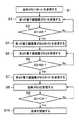
このような装置における金庫10の開錠動作を図2のフローチャートを参照して説明する。金庫10は常にID1としてID=Aを送信する(ステップS1)。このID1を第1の電子鍵装置20が受信する(ステップS2)。すると、第1の電子鍵装置20は、受信したID1がID=Aであるか、すなわち金庫10からの正規のIDであるか判別する(ステップS3)。そして、ID1がID=Aであると判別されると、第1の電子鍵装置20はID2としてID=Bを送信する(ステップS4)。このID2を第2の電子鍵装置30が受信する(ステップS5)。すると、第2の電子鍵装置30は、受信したID2がID=Bであるか、すなわち第1の電子鍵装置20からの正規のIDであるか判別する(ステップS6)。そして、ID2がID=Bであると判別されると、第2の電子鍵装置30はID3としてID=Cを送信する(ステップS7)。このID3を金庫10が受信する(ステップS8)。すると、金庫10は、受信したID3がID=Cであるか、すなわち第2の電子鍵装置30からの正規のIDであるか判別する(ステップS9)。そして、ID3がID=Cであると判別されると、金庫10で制御部12により施錠・開錠機構部13が操作されて開錠が行われる(ステップS10)。
【0017】
以上のように上記の装置によると、第1開錠者20aおよび第2開錠者30aが所有する第1の電子鍵装置20および第2の電子鍵装置30を持ち寄って複数のIDを使用してそれらが正しく送受信された場合にのみ金庫10で開錠が行われる。したがって、セキュリティが高い。また、機密性の高さによって電子鍵装置の数を容易に増減でき、適切なセキュリティの保持が可能である。さらに、金庫10側のシステムは無人化することができ、省力化を図ることができる。
【0018】
図3は本発明の開錠方法の第2の実施の形態を説明するために第2の金庫装置を示す構成図である。この第2の金庫装置では、第1の電子鍵装置20が送信したID2と第2の電子鍵装置30が送信したID3の両方を金庫10が受信して、これらID2とID3がID=BおよびID=Cであると判別されたとき、すなわち、金庫10が第1および第2の電子鍵装置20,30の両方から正規のIDを受信したとき、金庫10の制御部12で施錠・開錠機構部13を操作して金庫10の開錠が行われる。その他は図1の第1の金庫装置と同様であり、図中同一部分には図1と同一符号を付す。なお、金庫10のメモリ14には、第1および第2の電子鍵装置20,30から受信したID2とID3が“B”および“C”であることを判別するために比較用のID“B”および“C”が記憶される。
【0019】
この第2の金庫装置における詳細な開錠動作が図4のフローチャートに示されている。これを説明すると、金庫10は常にID1としてID=Aを送信する(ステップS21)。このID1を第1の電子鍵装置20が受信する(ステップS22)。すると、第1の電子鍵装置20は、受信したID1がID=Aであるか、すなわち金庫10からの正規のIDであるか判別する(ステップS23)。そして、ID1がID=Aであると判別されると、第1の電子鍵装置20はID2としてID=Bを送信する(ステップS24)。このID2を第2の電子鍵装置30が受信する(ステップS25)。同時にID2は金庫10で受信され、金庫10のメモリ14に記憶される(ステップS26)。第2の電子鍵装置30は、受信したID2がID=Bであるか、すなわち第1の電子鍵装置20からの正規のIDであるか判別する(ステップS27)。そして、ID2がID=Bであると判別されると、第2の電子鍵装置30はID3としてID=Cを送信する(ステップS28)。このID3を金庫10が受信し(ステップS29)、ID3を金庫10のメモリ14に記憶する(ステップS30)。同時に、金庫10は、メモリ14に記憶したID3がID=Cであるか、かつステップS26でメモリ14に記憶したID2がID=Bであるか、すなわち第1および第2の電子鍵装置20,30から正規のIDを受信したか判別する(ステップS31)。そして、ID2がID=B、ID3がID=Cであると判別されると、金庫10で制御部12により施錠・開錠機構部13が操作されて開錠が行われる(ステップS32)。
【0020】
このような第2の金庫装置によれば、第1の電子鍵装置20と第2の電子鍵装置30からの両方のIDを金庫10が受信するようにしたので、セキュリティをより高くすることができる。
【0021】
図5は本発明の開錠方法の第3の実施の形態を説明するために第3の金庫装置を示す構成図である。この第3の金庫装置では、第1の電子鍵装置20と第2の電子鍵装置30の両方にセンサ24,34が付加される。第1の電子鍵装置20に付加されたセンサ24は、第1の電子鍵装置20の所有者の生体的特徴(例えば指紋)を検出して、第1の電子鍵装置20の所有者が正規の所有者(第1開錠者20a)であるかを検出する。詳細には、センサ24から得られた情報と、予めメモリ23に記憶してある正規所有者の生体的特徴の情報とを判別部22で比較して、第1の電子鍵装置20の所有者が正規の所有者であるかを検出する。そして、第1の電子鍵装置20は、上記のようにして所有者が正規の所有者であると判別され、かつ受信したIDが金庫10からの正規のID(ID=A)であるとき、ID2としてID=Bを送信する。
【0022】
同様に、第2の電子鍵装置30に付加されたセンサ34は、第2の電子鍵装置30の所有者の生体的特徴(例えば指紋)を検出して、第2の電子鍵装置30の所有者が正規の所有者(第2開錠者30a)であるかを検出する。詳細には、センサ34から得られた情報と、予めメモリ33に記憶してある正規所有者の生体的特徴の情報とを判別部32で比較して、第2の電子鍵装置30の所有者が正規の所有者であるかを検出する。そして、第2の電子鍵装置30は、上記のようにして所有者が正規の所有者であると判別され、かつ受信したIDが第1の電子鍵装置20からの正規のID(ID=B)であるとき、ID3としてID=Cを送信する。第3の金庫装置のその他の構成は図1の第1の金庫装置と同一であり、図中同一部分には図1と同一符号を付す。
【0023】
この第3の金庫装置における詳細な開錠動作が図6のフローチャートに示されている。これを説明すると、金庫10は常にID1としてID=Aを送信する(ステップS41)。このID1を第1の電子鍵装置20が受信する(ステップS42)。すると、第1の電子鍵装置20は、受信したID1がID=Aであるか、すなわち金庫10からの正規のIDであるか判別する(ステップS43)。そして、ID1がID=Aであると、第1の電子鍵装置20はさらにセンサ24からの情報を基に所有者が正規の所有者であるか判別する(ステップS44)。そして、所有者も正規の所有者であると判別されると、第1の電子鍵装置20はID2としてID=Bを送信する(ステップS45)。このID2を第2の電子鍵装置30が受信する(ステップS46)。すると、第2の電子鍵装置30は、受信したID2がID=Bであるか、すなわち第1の電子鍵装置20からの正規のIDであるか判別する(ステップS47)。そして、ID2がID=Bであると、第2の電子鍵装置30はさらにセンサ34からの情報を基に所有者が正規の所有者であるか判別する(ステップS48)。そして、所有者も正規の所有者であると判別されると、第2の電子鍵装置30はID3としてID=Cを送信する(ステップS49)。このID3を金庫10が受信する(ステップS50)。すると、金庫10は、受信したID3がID=Cであるか、すなわち第2の電子鍵装置30からの正規のIDであるか判別する(ステップS51)。そして、ID3がID=Cであると判別されると、金庫10で制御部12により施錠・開錠機構部13が操作されて開錠が行われる(ステップS52)。
【0024】
このような第3の金庫装置によれば、第1および第2の電子鍵装置20,30で所有者が正規かということも判断して第1および第2の電子鍵装置20,30からIDを送信するようにしたので、よりセキュリティが高まる。
【0025】
なお、以上の実施の形態は、金庫を開錠する場合について説明したが、本発明の開錠方法は、出入口扉など他の開錠対象物を開錠する場合にも勿論利用できる。
【0026】
【発明の効果】
以上詳細に説明したように本発明の開錠方法によれば、無線と複数の識別符号を使用して開錠することにより、開錠対象物側のシステムを無人化して省力化が可能であり、しかもセキュリティを高めることができる。
【図面の簡単な説明】
【図1】本発明による開錠方法の第1の実施の形態を説明するために第1の金庫装置を示す構成図。
【図2】第1の金庫装置における開錠動作を詳細に示すフローチャート。
【図3】本発明による開錠方法の第2の実施の形態を説明するために第2の金庫装置を示す構成図。
【図4】第2の金庫装置における開錠動作を詳細に示すフローチャート。
【図5】本発明による開錠方法の第3の実施の形態を説明するために第3の金庫装置を示す構成図。
【図6】第3の金庫装置における開錠動作を詳細に示すフローチャート。
【符号の説明】
10 金庫
20 第1の電子鍵装置
30 第2の電子鍵装置[0001]
BACKGROUND OF THE INVENTION
The present invention relates to an unlocking method for unlocking an object to be unlocked, for example, a safe.
[0002]
[Prior art]
Conventionally, as a method for unlocking a safe, there is one disclosed in, for example, Japanese Patent Laid-Open No. 60-128764. This is the following method. The safe clerk goes to the site and calls from the public telephone to the telephone office reception desk. The safe clerk and the reception desk corresponder make a call, and during the call, the safe clerk sends out an ID number using a push button dial, or conveys the cipher by voice. Next, the responder at the reception desk checks the ID number or encryption, and if it is found to be legitimate, sends a lock release command to the public telephone, and at the same time invalidates the current ID number or encryption and obtains a new ID number or encryption. Set. This lock release command releases the lock A mechanism of the public telephone, and the safe occupant opens the lock B mechanism using the combined key. The safe is now unlocked.
[0003]
[Problems to be solved by the invention]
However, the conventional unlocking method as described above has a problem that a dedicated operator is required to unlock the safe and labor saving cannot be achieved. Further, if one ID number can be known, a single person can open the lock, and there is a limit in ensuring security.
[0004]
The present invention has been made in view of the above points, and an object thereof is to provide an unlocking method that can save labor by unmanning the system on the side of the unlocking object and that can ensure high security. To do.
[0005]
[Means for Solving the Problems]
The first unlocking method of the present invention includes an unlocking object capable of transmitting and receiving an identification code wirelessly, and a plurality of electronic key devices capable of transmitting and receiving the identification code wirelessly, wherein the plurality of electronic key devices are asbeginning the identification code transmitted from the unlocked object, if the received identification code is correct matches the identification code stored,the next stage of the electronic different identification code from the already identified codes usedThe transmission to thekey device is repeated in a chain, a predetermined identification code is transmitted from the last stage electronic key device to the unlocking object, and the unlocking object is transmitted from the last stage electronic key device. The unlocking operation is performed when the identification code is received and coincides with the stored identification code and is correct.
[0006]
The second unlocking method of the present invention includes an unlocking object capable of transmitting and receiving an identification code wirelessly and a plurality of electronic key devices capable of transmitting and receiving the identification code wirelessly, and the plurality of electronic key devices include When the identification code transmitted from the object to be unlocked is astarting point and the received identification code matches and is correct with the stored identification code, and the owner of the electronic key device is properly owned from the detected biological characteristics. If it is recognized that the user is an authorized person, the transmission of an identification code different from the identification code already used to thenext-stage electronic key device is repeated in a chain, and the predetermined identification code is unlocked from the last-stage electronic key device. When the unlocking object receives the identification code transmitted from the last stage electronic key device and matches the stored identification code, the unlocking operation is performed. It is characterized by that.
[0009]
DETAILED DESCRIPTION OF THE INVENTION
Next, an embodiment of the unlocking method according to the present invention will be described in detail with reference to the accompanying drawings. FIG. 1 is a block diagram showing a first safe apparatus for explaining the first embodiment of the unlocking method of the present invention. The first safe device includes a safe 10, a first
[0010]
The safe 10 includes a transmission /
[0011]
The first
[0012]
The second
[0013]
The transmission /
[0014]
It also has a function of detecting that a communication partner has entered the communication area before performing data communication. After detecting the communication partner, it is determined whether the connection partner is selected or suitable as the connection partner, and connection processing (calling) is performed in order to perform data communication.
If the detection side is a master, the master side has detection and connection buttons. When the user presses the detection button, the master transmits a detection signal and waits for reception of a response signal. In order to receive the detection signal, the detected side (slave) periodically performs a receiving operation, and when receiving the detection signal, returns its own terminal identification number as a response signal.
And if the master side succeeds in receiving the response signal, the terminal identification number is displayed by providing a display, for example. When the user wants to connect, the master enters a connection process by selecting a connection partner and pressing the connection button, and starts data communication.
[0015]
In this embodiment, communication between a master and a plurality of slaves and a link centering on the master are configured.
When the communication connection is started, the master assigns a temporary address to the slave. The slave determines whether it is addressed to itself from the received address, fetches data if it is addressed to itself, and discards it if it is not addressed to itself. Even while data communication between the master and the slave is performed, a slave can be added at any time by performing the terminal detection / connection procedure in the communication area. Also, the temporary address assigned to the slave can be abandoned at the end of data communication. In this manner, communication with a large number of terminals becomes possible by repeatedly adding and releasing slaves in a time-sharing manner.
[0016]
The unlocking operation of the safe 10 in such an apparatus will be described with reference to the flowchart of FIG. The safe 10 always transmits ID = A as ID1 (step S1). The first electronic
[0017]
As described above, according to the above-described device, the first electronic
[0018]
FIG. 3 is a block diagram showing a second safe apparatus for explaining the second embodiment of the unlocking method of the present invention. In this second safe device, the safe 10 receives both ID2 transmitted by the first electronic
[0019]
The detailed unlocking operation in the second safe apparatus is shown in the flowchart of FIG. Explaining this, the safe 10 always transmits ID = A as ID1 (step S21). The first electronic
[0020]
According to such a second safe device, since the safe 10 receives both IDs from the first electronic
[0021]
FIG. 5 is a block diagram showing a third safe apparatus for explaining the third embodiment of the unlocking method of the present invention. In the third safe device,
[0022]
Similarly, the
[0023]
The detailed unlocking operation in the third safe device is shown in the flowchart of FIG. Explaining this, the safe 10 always transmits ID = A as ID1 (step S41). The first electronic
[0024]
According to such a third safe device, the first and second electronic
[0025]
In the above embodiment, the case where the safe is unlocked has been described. However, the unlocking method of the present invention can of course be used when unlocking other objects to be unlocked such as the doorway.
[0026]
【The invention's effect】
As described in detail above, according to the unlocking method of the present invention, by unlocking using the radio and a plurality of identification codes, it is possible to save labor by unmanning the system on the unlocking object side. And security can be improved.
[Brief description of the drawings]
FIG. 1 is a configuration diagram showing a first safe device for explaining a first embodiment of an unlocking method according to the present invention;
FIG. 2 is a flowchart showing in detail an unlocking operation in the first safe device.
FIG. 3 is a block diagram showing a second safe apparatus for explaining a second embodiment of the unlocking method according to the present invention.
FIG. 4 is a flowchart showing in detail an unlocking operation in the second safe apparatus.
FIG. 5 is a configuration diagram showing a third safe apparatus for explaining a third embodiment of the unlocking method according to the present invention;
FIG. 6 is a flowchart showing in detail an unlocking operation in the third safe device.
[Explanation of symbols]
10
Claims (2)
Translated fromJapanese前記複数の電子鍵装置は、前記開錠対象物から送信された識別符号を発端として、受信した識別符号が記憶している識別符号と一致し正しい場合に、既に使用された識別符号とは異なる識別符号を次段の電子鍵装置に送信することを連鎖的に繰り返し、最終段の電子鍵装置から所定の識別符号を前記開錠対象物に送信し、
前記開錠対象物は前記最終段の電子鍵装置から送信された前記識別符号を受信してそれが記憶している識別符号と一致し正しい場合に開錠操作が行われることを特徴とする開錠方法。An unlocking object capable of transmitting and receiving the identification code wirelessly, and a plurality of electronic key devices capable of transmitting and receiving the identification code wirelessly,
The plurality of electronic key devices are different from the identification codes already used when the identification code transmitted from the unlocking object is astarting point and the received identification code matches and is correct. Sending the identification code tothe electronic key device at thenext stage is repeated in a chain, and a predetermined identification code is transmitted from the electronic key device at the final stage to the unlocking object,
The unlocking object receives the identification code transmitted from the last stage electronic key device, and the unlocking operation is performed when the identification code matches the stored identification code and is correct. Lock method.
前記複数の電子鍵装置は、前記開錠対象物から送信された識別符号を発端として、受信した識別符号が記憶している識別符号と一致し正しい場合に、かつ検出した生体的特徴から電子鍵装置所有者が正規の所有者と認めた場合に、既に使用された識別符号とは異なる識別符号を次段の電子鍵装置に送信することを連鎖的に繰り返し、最終段の電子鍵装置から所定の識別符号を前記開錠対象物に送信し、
前記開錠対象物は前記最終段の電子鍵装置から送信された前記識別符号を受信してそれが記憶している識別符号と一致し正しい場合に開錠操作が行われることを特徴とする開錠方法。An unlocking object capable of transmitting and receiving the identification code wirelessly, and a plurality of electronic key devices capable of transmitting and receiving the identification code wirelessly,
Said plurality of electronic key devices, wherein thebeginning of the identification code transmitted from the unlocked object, if the received identification code is correct matches the identification code stored therein and an electronic key from the detected biometric features When the device owner recognizes that the device is a legitimate owner, the identification code different from the identification code already used is repeatedly transmitted tothe electronic key device at thenext stage, and the electronic key device at the final stage repeats the predetermined process. Is transmitted to the unlocking object,
The unlocking object receives the identification code transmitted from the last stage electronic key device, and the unlocking operation is performed when the identification code matches the stored identification code and is correct. Lock method.
Priority Applications (8)
| Application Number | Priority Date | Filing Date | Title |
|---|---|---|---|
| JP2000292932AJP3864300B2 (en) | 2000-09-26 | 2000-09-26 | Unlocking method |
| ES01954391TES2200732T3 (en) | 2000-09-26 | 2001-07-31 | METHOD FOR UNLOCKING AN ELECTRONIC CERADURE. |
| US10/381,337US6903651B2 (en) | 2000-09-26 | 2001-07-31 | Method of unlocking electronic lock |
| DE0001331329TDE01954391T1 (en) | 2000-09-26 | 2001-07-31 | METHOD FOR OPENING AN ELECTRONIC LOCK |
| PCT/JP2001/006591WO2002027126A1 (en) | 2000-09-26 | 2001-07-31 | Method of unlocking electronic lock |
| EP01954391AEP1331329B1 (en) | 2000-09-26 | 2001-07-31 | Method of unlocking electronic lock |
| DE60135864TDE60135864D1 (en) | 2000-09-26 | 2001-07-31 | METHOD FOR OPENING AN ELECTRONIC LOCK |
| CNB018163319ACN1242147C (en) | 2000-09-26 | 2001-07-31 | Method of unlocking electronic lock |
Applications Claiming Priority (1)
| Application Number | Priority Date | Filing Date | Title |
|---|---|---|---|
| JP2000292932AJP3864300B2 (en) | 2000-09-26 | 2000-09-26 | Unlocking method |
Publications (2)
| Publication Number | Publication Date |
|---|---|
| JP2002097825A JP2002097825A (en) | 2002-04-05 |
| JP3864300B2true JP3864300B2 (en) | 2006-12-27 |
Family
ID=18775796
Family Applications (1)
| Application Number | Title | Priority Date | Filing Date |
|---|---|---|---|
| JP2000292932AExpired - Fee RelatedJP3864300B2 (en) | 2000-09-26 | 2000-09-26 | Unlocking method |
Country Status (7)
| Country | Link |
|---|---|
| US (1) | US6903651B2 (en) |
| EP (1) | EP1331329B1 (en) |
| JP (1) | JP3864300B2 (en) |
| CN (1) | CN1242147C (en) |
| DE (2) | DE60135864D1 (en) |
| ES (1) | ES2200732T3 (en) |
| WO (1) | WO2002027126A1 (en) |
Families Citing this family (10)
| Publication number | Priority date | Publication date | Assignee | Title |
|---|---|---|---|---|
| JP4503280B2 (en)* | 2003-12-16 | 2010-07-14 | 亮 田口 | Electronic lock unlocking authentication system by tally verification |
| CN100497050C (en)* | 2004-01-26 | 2009-06-10 | 东芝解决方案株式会社 | Security system, authentication system for vehicle, method and program |
| JP4723352B2 (en)* | 2005-11-10 | 2011-07-13 | 株式会社東海理化電機製作所 | Electronic key system and communication unit |
| FR2895433B1 (en)* | 2005-12-23 | 2009-11-06 | Serv Trayvou Interverrouillage | SECURITY SYSTEM BELONGING TO AN INTERLOCKING DEVICE HAVING A SET OF ELECTRONIC KEYS |
| JP4593530B2 (en)* | 2006-07-03 | 2010-12-08 | 日本電信電話株式会社 | Key release determination system, key release determination method, key release determination device, and distributed key device |
| CN102279984B (en)* | 2010-06-12 | 2013-07-03 | 上海鸿隆电子技术有限公司 | Inner container of wireless power supply ticket box |
| CN102268939A (en)* | 2011-06-23 | 2011-12-07 | 湖北盛佳电器设备有限公司 | Electronic cluster lock system |
| CN108765649A (en)* | 2018-05-14 | 2018-11-06 | 吴东辉 | Electronic lock control method and device and system |
| CN109779411B (en)* | 2019-02-28 | 2020-06-30 | 北京沃东天骏信息技术有限公司 | Block chain-based coded lock unlocking method, device and equipment |
| CN110644859A (en)* | 2019-08-26 | 2020-01-03 | 中山欧朗金属制品有限公司 | Lock and control method thereof |
Family Cites Families (13)
| Publication number | Priority date | Publication date | Assignee | Title |
|---|---|---|---|---|
| JPS60128764A (en) | 1983-12-16 | 1985-07-09 | Nippon Telegr & Teleph Corp <Ntt> | Locking release system of lock |
| FR2585153A1 (en)* | 1985-07-17 | 1987-01-23 | Desgorces Jean | Method of control of sequential operations by presentation of fingerprints, and its application to strongrooms |
| US4918431A (en)* | 1988-10-31 | 1990-04-17 | Motorola, Inc. | Method and apparatus for automatically adjusting the output power of a transmitter |
| JPH02171893A (en)* | 1988-12-23 | 1990-07-03 | Matsushita Electric Works Ltd | Valuables keeping device |
| JPH05233896A (en)* | 1992-02-24 | 1993-09-10 | Yuuseidaijin | In/out managing device |
| JP2697605B2 (en)* | 1994-04-20 | 1998-01-14 | 日産自動車株式会社 | Vehicle antitheft device and method for registering ID number of vehicle antitheft device |
| US5668876A (en)* | 1994-06-24 | 1997-09-16 | Telefonaktiebolaget Lm Ericsson | User authentication method and apparatus |
| JPH08185587A (en)* | 1994-12-28 | 1996-07-16 | Matsushita Electric Works Ltd | Apparatus arrangement box |
| JP3477699B2 (en) | 1994-12-29 | 2003-12-10 | マツダ株式会社 | Vehicle anti-theft device |
| DE19516992C1 (en)* | 1995-05-09 | 1996-04-04 | Siemens Ag | Operating system for automobile anti-theft device |
| US5777547A (en)* | 1996-11-05 | 1998-07-07 | Zeftron, Inc. | Car identification and ordering system |
| DE19722424C5 (en)* | 1997-05-28 | 2006-09-14 | Telefonaktiebolaget Lm Ericsson (Publ) | Method of securing access to a remote system |
| US6795920B1 (en)* | 1999-06-30 | 2004-09-21 | International Business Machines Corporation | Vault controller secure depositor for managing secure communication |
- 2000
- 2000-09-26JPJP2000292932Apatent/JP3864300B2/ennot_activeExpired - Fee Related
- 2001
- 2001-07-31USUS10/381,337patent/US6903651B2/ennot_activeExpired - Fee Related
- 2001-07-31DEDE60135864Tpatent/DE60135864D1/ennot_activeExpired - Lifetime
- 2001-07-31ESES01954391Tpatent/ES2200732T3/ennot_activeExpired - Lifetime
- 2001-07-31WOPCT/JP2001/006591patent/WO2002027126A1/enactiveIP Right Grant
- 2001-07-31CNCNB018163319Apatent/CN1242147C/ennot_activeExpired - Fee Related
- 2001-07-31EPEP01954391Apatent/EP1331329B1/ennot_activeExpired - Lifetime
- 2001-07-31DEDE0001331329Tpatent/DE01954391T1/enactivePending
Also Published As
| Publication number | Publication date |
|---|---|
| CN1242147C (en) | 2006-02-15 |
| US20040012484A1 (en) | 2004-01-22 |
| ES2200732T3 (en) | 2009-03-01 |
| DE01954391T1 (en) | 2004-04-15 |
| EP1331329B1 (en) | 2008-09-17 |
| CN1466648A (en) | 2004-01-07 |
| EP1331329A4 (en) | 2007-05-09 |
| WO2002027126A1 (en) | 2002-04-04 |
| DE60135864D1 (en) | 2008-10-30 |
| ES2200732T1 (en) | 2004-03-16 |
| JP2002097825A (en) | 2002-04-05 |
| US6903651B2 (en) | 2005-06-07 |
| EP1331329A1 (en) | 2003-07-30 |
Similar Documents
| Publication | Publication Date | Title |
|---|---|---|
| JPS63574A (en) | Unlocking control apparatus | |
| JP3864300B2 (en) | Unlocking method | |
| JP6351425B2 (en) | Keyless entry device and control method thereof | |
| US20090066477A1 (en) | Authentication apparatus | |
| JP5436587B2 (en) | Electronic key device and base unit used for electronic key device | |
| JP3386430B2 (en) | Key with authentication opening and closing function and IC card | |
| EP3640880B1 (en) | Vehicular control system | |
| JP2003056232A (en) | Unlocking method and lock control device | |
| JP6702840B2 (en) | Wireless communication correctness determination system | |
| CN111179474B (en) | Unlocking processing method and device for vehicle authenticated by user and electronic equipment | |
| JP2009174224A (en) | Door locking/unlocking control device and door locking/unlocking control system | |
| JP2006342620A (en) | Keyless entry unit | |
| JP3741023B2 (en) | In-vehicle communication device and communication method | |
| JP2020088408A (en) | Authentication system and authentication method | |
| JPH1046885A (en) | Electronic lock system | |
| JP2011111845A (en) | Electronic key system | |
| JP5140578B2 (en) | Portable terminal, mutual authentication system, portable terminal control method, and portable terminal control program | |
| JPH09279917A (en) | Keyless entry device | |
| JP2018180842A (en) | User authentication system and user authentication method | |
| JP2017150294A (en) | Key authentication system | |
| JP2021111038A (en) | Authentication system, authentication method, and authentication device | |
| KR101791975B1 (en) | digital door lock opening device using genuine product remote controller for vehicle and digital door lock system | |
| JP2021129158A (en) | Authentication system and authentication method | |
| JP3022832B2 (en) | How to lock a mobile phone dial using external media | |
| JP2019218699A (en) | Locking and unlocking system for building |
Legal Events
| Date | Code | Title | Description |
|---|---|---|---|
| A131 | Notification of reasons for refusal | Free format text:JAPANESE INTERMEDIATE CODE: A131 Effective date:20051018 | |
| A521 | Written amendment | Free format text:JAPANESE INTERMEDIATE CODE: A523 Effective date:20051216 | |
| A131 | Notification of reasons for refusal | Free format text:JAPANESE INTERMEDIATE CODE: A131 Effective date:20060411 | |
| A521 | Written amendment | Free format text:JAPANESE INTERMEDIATE CODE: A523 Effective date:20060413 | |
| TRDD | Decision of grant or rejection written | ||
| A01 | Written decision to grant a patent or to grant a registration (utility model) | Free format text:JAPANESE INTERMEDIATE CODE: A01 Effective date:20060821 | |
| A61 | First payment of annual fees (during grant procedure) | Free format text:JAPANESE INTERMEDIATE CODE: A61 Effective date:20060919 | |
| R150 | Certificate of patent or registration of utility model | Free format text:JAPANESE INTERMEDIATE CODE: R150 | |
| FPAY | Renewal fee payment (event date is renewal date of database) | Free format text:PAYMENT UNTIL: 20091013 Year of fee payment:3 | |
| FPAY | Renewal fee payment (event date is renewal date of database) | Free format text:PAYMENT UNTIL: 20101013 Year of fee payment:4 | |
| FPAY | Renewal fee payment (event date is renewal date of database) | Free format text:PAYMENT UNTIL: 20111013 Year of fee payment:5 | |
| FPAY | Renewal fee payment (event date is renewal date of database) | Free format text:PAYMENT UNTIL: 20121013 Year of fee payment:6 | |
| FPAY | Renewal fee payment (event date is renewal date of database) | Free format text:PAYMENT UNTIL: 20121013 Year of fee payment:6 | |
| S111 | Request for change of ownership or part of ownership | Free format text:JAPANESE INTERMEDIATE CODE: R313111 | |
| FPAY | Renewal fee payment (event date is renewal date of database) | Free format text:PAYMENT UNTIL: 20121013 Year of fee payment:6 | |
| R350 | Written notification of registration of transfer | Free format text:JAPANESE INTERMEDIATE CODE: R350 | |
| FPAY | Renewal fee payment (event date is renewal date of database) | Free format text:PAYMENT UNTIL: 20131013 Year of fee payment:7 | |
| LAPS | Cancellation because of no payment of annual fees |