JP3862899B2 - Optimization device - Google Patents
Optimization deviceDownload PDFInfo
- Publication number
- JP3862899B2 JP3862899B2JP26414899AJP26414899AJP3862899B2JP 3862899 B2JP3862899 B2JP 3862899B2JP 26414899 AJP26414899 AJP 26414899AJP 26414899 AJP26414899 AJP 26414899AJP 3862899 B2JP3862899 B2JP 3862899B2
- Authority
- JP
- Japan
- Prior art keywords
- solution
- crew
- segment
- flight
- chromosome
- Prior art date
- Legal status (The legal status is an assumption and is not a legal conclusion. Google has not performed a legal analysis and makes no representation as to the accuracy of the status listed.)
- Expired - Fee Related
Links
Images


Classifications
- G—PHYSICS
- G06—COMPUTING OR CALCULATING; COUNTING
- G06Q—INFORMATION AND COMMUNICATION TECHNOLOGY [ICT] SPECIALLY ADAPTED FOR ADMINISTRATIVE, COMMERCIAL, FINANCIAL, MANAGERIAL OR SUPERVISORY PURPOSES; SYSTEMS OR METHODS SPECIALLY ADAPTED FOR ADMINISTRATIVE, COMMERCIAL, FINANCIAL, MANAGERIAL OR SUPERVISORY PURPOSES, NOT OTHERWISE PROVIDED FOR
- G06Q99/00—Subject matter not provided for in other groups of this subclass
Landscapes
- Business, Economics & Management (AREA)
- Physics & Mathematics (AREA)
- General Business, Economics & Management (AREA)
- General Physics & Mathematics (AREA)
- Engineering & Computer Science (AREA)
- Theoretical Computer Science (AREA)
- Management, Administration, Business Operations System, And Electronic Commerce (AREA)
Description
Translated fromJapanese【0001】
【発明の属する技術分野】
本発明は、最適化装置に関する。
【0002】
【従来の技術】
最適化は、高度なコンピュータ利用における知的処理の根幹をなすものであり、スケジューリング問題、配車計画問題、パターン推定、時間割り自動割りつけ、乗員配置問題等の具体的な応用分野がある。しかしながら、計算量や記憶装置の記憶容量の制限から、このような大規模な最適化問題を、直接、全解探索で解くことは現実的ではない。
【0003】
近年のコンピュータの性能の向上に伴い、従来のエキスパートシステム等で解決が困難であった問題を解決する手段として、確率的最適化手法(ジミュレーティド・アニーリング、GA(遺伝的アルゴリズム))等が注目をあび、その実用化のための研究がなされている。様々な最適化手法の中でも、特に、GAは、その手法の単純さから注目されている。
【0004】
また、全ての産業において、人員のスケジュールは根本的な問題であるが、これは、最適化問題の1つとして捉えることができる。この問題は、あらゆる産業分野で、コスト削減に決定的な影響を与える。
【0005】
例えば、航空分野では、世界的に、燃料代の次に人件費が大きいといわれており、この人件費の削減が大きな課題となっている。
組み合わせ問題を解く一般的手法として、LP(Linear Progrming) やIP(Integere Programing)のような、連立方程式によるモデル化と数学的求解が用いられ、問題をSet PartioningまたはSet Covering問題として解いている。
【0006】
しかし、これらの手法では、複雑な問題を解く場合、定式化そのものが難しく、例え、定式化できたとしても、大規模問題では定義性や組み合わせ数が増大し、実用的な時間内に解が得られない。しかも、何時間実行させても、結局、解が見つからない場合がある等の難点がある。
【0007】
また、高速化のためにカラムジェネレーション等の手法も用いられているが、カラムの生成時間やメモリ容量の制限等の問題から、大規模な問題では様々な限界に直面する。
【0008】
このような従来手法を解決する手段として注目されたのがGA(Genetic Algorithms)である。GAでは問題をモデル化し、そのパラメータを染色体で表現する。GAで最適化を行う際には、染色体をデコードしてパラメータに変換し、そのパラメータを問題モデルに投入してその評価を行い、その評価値を染色体の適応度として用いることで、個体(染色体)を進化させ、最適化を進展させる。
【0009】
【発明が解決しようとする課題】
1. 問題の記述性の問題
IP/LPでは、問題の記述を行列の形式で表現しなけらばならず、この方式では、個別の条件を詳細に反映するのは困難である。
【0010】
カラムジェネレーションで解く一つの解法では、問題をルール化し、カラムジェネレーション時の生成ルールとして問題の詳細を記述するものもあるが、問題を如何にルールで表現するか、ルールの網羅性や妥当性の検証、ルール間の無矛盾性の確保等、様々の問題を抱えている。
2. 探索手法の問題
従来手法にはない長所を持つGAであっても、解空間が膨大になると求解能力にも、以下のような限界が生じてくる。
【0011】
1) GAの染色体が、解空間の全てをカバーできない。
2) 解空間を一様に覆うようなコーディングをすると、制約違反がある領域や、解としては不適当な領域が非常に多くなり、最適化が効率的に行えない。
【0012】
3) 解生成ルールを用いた解生成が望ましい場合があるが、単純にルールだけを用いて解を生成すると、求解手法の硬直化を招き、良質の解が得られなくなる。
3. スケジュール期間と作業の規則性の問題
実際にスケジュールを行わればならない対象は、日によって特定の作業があったり、なかったりするかなり複雑なものであるが、従来手法ではこれを直接に扱うことが困難であるため、同じ作業が連日続く事を暗黙の前提として、数日に渡るスケジュールを組んでいる。これを、Daily Modelという。
【0013】
スケジュール対象の作業は、今後、ますます不定期になるので、Daily Modelのような解法は、ますます実体に則さないスケジューリングになっている。
【0014】
ところで、米国の航空乗務員スケジュールのように、週末だけ一部の作業のないようなものが考えられ、これをWeekly Modelという。
更に、全ての不定期なスケジュール対象を取り入れ、スケジュール期間が1〜2ヵ月程度になるものをFully Dated Modelといい、これを直接扱った例は知られていない。
【0015】
本発明の目的は、従来は解を得ることが不可能であった、Fully Dated Modelのような、広範囲な探索空間を有し、かつ制約条件の多い制約充足最適化問題の解を自動生成可能な最適化装置を実現することである。
【0016】
【課題を解決するための手段】
本発明の最適化装置は、以下の各手段を備える。
求解データ提示手段は、遺伝的アルゴリズムにより求められた染色体として表現された求解データを問題モデルに適用した結果得られる解の評価値を、前記染色体の適応度として受け取り、前記染色体を遺伝的アルゴリズムにより進化させることにより、求解データの最適化を進行させる。
【0017】
求解手段は、該求解データ提示手段から受け取る前記求解データから、少なくとも局所探索手法と確率的探索手法の併用により、前記問題モデルの解を求める。
【0018】
評価値算出手段は、該求解手段により求められた解の評価値を算出し、それを前記求解データ提示手段に出力する。
解取得手段は、前記求解データ提示手段、前記求解手段、及び前記評価値算出手段を制御して、前記問題モデルの最終的な解を求める。
【0022】
前記問題モデルは、ある単位の作業の一連の繋がりから成る1日単位の複数の第1のスケジュールを、複数日にまたがって接続することにより得られる複数日に跨がる第2のスケジュールの解を求める制約充足最適化問題のモデルである。
【0023】
このような構成において、前記作業は、航空機の便の乗務であり、この場合、前記第1のスケジュールは1日の乗務パターンであり、前記第2のスケジュールは複数日に跨がる乗務パターンである。この場合、前記局所探索手法は、期割れとなった便の残りの運航日に運航可能な接続便を探索する際に使用される。また、前記確率的探索手法は、次に接続する便を探索するために使用される。
【0024】
また、前記求解手段は、前記染色体の第1の遺伝子と、各シップライン毎に設けられた、該各シップラインの分割方法を確率的に決定するための情報が格納されているセグメンテーション確率テーブルとを使用して、各シップラインをセグメントに分割し、該分割されたセグメントを接続することにより前記複数日に跨がる乗務パターンを作成すると共に、前記染色体の第2の遺伝子と、各便毎に設けられた、該各便に接続すべき便に関する接続確率値が格納されているセグメント接続確率テーブルとを使用して、次に接続すべきセグメントを確率的に探索する。
【0028】
このような態様において、前記求解手段は、前記染色体の第2の遺伝子と各便毎に設けられた、該各便に接続すべき便に関する接続確率値が格納されているセグメント接続確率テーブルとを使用して、次に接続すべきセグメントを確率的に探索する。
【0031】
【発明の実施の形態】
以下、図面を参照しながら本発明の実施形態を説明する。
図1は、本発明の実施形態の原理を説明する図である。尚、図1では、最適化機構としてGA(Geneteic Algorithms) を採用しているが、本発明の最適化機構はGAに限定されるものではない。
【0032】
GA処理部1は、適応度計算器1−1、選択操作器1−2、交叉操作器1−3、及び突然変異操作器1−4から構成される。
適応度計算器1−1は、自らが管理する、ある世代の染色体集団2内の各染色体2−1の適応度を計算する。選択操作器1−2は、適応度計算器1−1の計算結果に基づき、適応度の高い染色体21−が、より多く次世代の親として選ばれるように選択操作を行う。
【0033】
交叉操作器1−3は、選択操作器1−2によって選択された染色体2−1をランダムに2個ずつ組み合わせ、ある確率(交叉率)で、2つの染色体2−1の遺伝子列を部分的に交換する。
【0034】
突然変異操作器1−4は、ある確率(突然変異率)で、染色体2−1の各遺伝子座の遺伝子を他の対立遺伝子と入れ換える。
適応度計算器1−1は、突然変異操作器1−4により得られた染色体2−1により、染色体集団2内のN個の染色体2−1を次世代に置き換える。
【0035】
染色体2−1は、m個(mは任意の整数)の遺伝子から構成されている。各遺伝子座の遺伝子は文字列、ビット列、整数配列等で表現される。各染色体2−1は、解2−2と適応度2−3を有する。解2−1は、デコード処理器3により、問題モデル計算部4内部の問題モデルのパラメータに変換された染色体2−1が問題モデルで評価される際に生成される問題の解である。適応度2−3は、解2−2の問題モデルでの評価値(目的関数値)によって決定される染色体2−1の適応度である。
【0036】
デコード処理部3は、染色体集団2から染色体2−1を順次取り出し、染色体2−1の各遺伝子を、問題モデル計算部4で計算される問題のパラメータ3−1にデコードする。このデコード処理において、一部の遺伝子について、確率テーブル(不図示)が利用されることが、本発明の特徴の一つである。
【0037】
問題モデル計算部4は、デコード処理部3から問題のパラメータ3−1を受け取り、それを基に、対象の問題の解を生成し、その解の評価値を算出する。この評価値は、例えば、染色体2−1の適応度に等しい。
【0038】
問題モデル計算部4は、コントーラ4−1、局所探索手法器4−2、GA探索器4−3、確率的探索器4−4、制約違反判定器4−5、制約違反処理器4−6、及び解・適応度算出器4−7を備えている。
【0039】
コントーラ4−1は、問題モデル計算部4全体を制御し、解の生成過程において、その時の条件に応じて、局所探索手法器4−2、GA探索器4−3、または確率的探索器4−4を起動する。例えば、局所探索手法により新たな解の候補を探索する必要が生じた場合には、局所探索手法器4−2を起動して、新たな解の候補を探索する。また、染色体2−1の遺伝子のデコードにより新たな解の候補を探索可能なときは、GA探索器4−3を起動して、新たな解の候補を検索する。また、さらに、確率的探索器4−4により新たな解の候補を検索可能なときは、確率的探索器4−4を起動して、新たな解の候補を探索する。
【0040】
局所探索手法器4−2、GA探索器4−3、または確率的探索器4−4の処理が繰り返し行われることにより、最適解または準最適解が求められるが、その過程で、得られた途中の解が制約違反を起こしていないか否かが制約違反判定器4−5によって判定される。
【0041】
制約違反判定器4−5によって制約違反が判定されると、制約違反処理器4−6が起動され、局所探索手法器4−2、GA探索器4−3、または確率的探索器4−4によって追加された解の一部を除去する等の処理がなされ、処理はコントーラ4−1に移行する。コントーラ4−1は、解の作成処理が終了したか判断し、まだ、終了していなければ、上述したような判断を行い、局所探索手法器4−2、GA探索器4−3、または確率的探索器4−4を起動する。
【0042】
以上のようなループ処理を続けながら、コントーラ4−1が解の生成の終了を判断すると、解・適応度算出器4−7はコントーラ4−1から生成された解を受け取り、その解の評価値(染色体2−1の適応度)を算出する。そして、解・適応度算出器4−7は、デコード処理部3によってデコードされた染色体2−1の解2−2及び適応度2−3を染色体集団2に返す。
【0043】
本発明の原理の要点を簡単に説明する。
〔1〕 デコード処理部3のデコードにより得られた問題パラメータ3−1が問題モデル計算部4に投入されると、問題モデル計算部4はその問題パラメータ3−1を基に、問題モデル計算部4によって問題の解を生成する。
【0044】
問題モデル計算部4内部の問題モデルは、予め組み込まれたパラメータによって、問題を正しく記述できる状態になっている。
〔2〕 問題モデル計算部4は、コントーラ4−1の制御によって、局所探索手法器4−2、GA探索器4−3、または確率的探索器4−4を起動しながら、問題モデルの解を生成する。問題モデル計算部4で生成された解は、制約違反判定器4−1によって制約違反を起こしていないかチェックされ、制約違反がなければ、問題モデル計算部4で処理は続行される。一方、制約違反が発見された場合には、制約違反処理器4−6によって、局所探索手法器4−2、GA探索器4−3、または確率的探索器4−4によって新たに付加された解の一部を除去する処理がなされる。
【0045】
〔3〕 局所探索手法器4−2は、局所探索手法により解の候補を探索する。例えば乗務パターンの生成において、期割れの便が生じた場合、その便の期割れを補完する接続便を探索する。
【0046】
〔4〕 GA探索器4−3は、例えば、染色体2−1の一部の遺伝子の情報を基に、解の候補を探索する。
〔5〕 確率的探索器4−4は、解の候補を、確率テーブル(不図示)を参照して探索する。確率テーブルにおいては、予め計算された解候補の確率と、これまでに生成した解と解の候補との関係から、新たな確率が計算され、この確率に応じて解の候補を提示する。確率テーブルから解候補として提示されるものには、単純な確率だけではなく、問題の特質に合わせたものも含まれる。
【0047】
確率的探索器4−4は、例えば、GA探索器4−3による処理が不可能になった場合に起動される。
〔6〕 問題モデル計算部4により、最終的な解の生成が終了した後に、その解の適応度の計算を行い、染色体集団2に、〔1〕でデコードされた染色体2−1の解2−2とその適応度2−3を返す。
【0048】
〔7〕 〔1〕〜〔6〕が、染色体集団2内の全ての染色体2−1に対して実施され、それらに対応する解2−2と適応度2−3が求められると、適応度計算器1−1は、染色体集団2の世代交代を行い、全体の最適化を進行させる。
【0049】
図2は、図1の最適化装置の処理アルゴリズムを説明するフローチャートである。尚、このフローチャートは1つの染色体2−1を対象としたフローチャートである。
【0050】
まず、デコード処理部3が染色体集団2から染色体2−1を一つ取り出し、それをデコードする(ステップS1)。このデコードによって、探索の開始点、探索順等のデータ(染色体情報)が得られる(ステップS2)。これらのデータは、例えば、後述する染色体40の遺伝子41〜43をデコードすることによって得られる。
【0051】
次に、問題モデル計算部4が、上記デコードによって得られた染色体情報に従って解の生成を開始する。問題モデル計算部4は、求解の状態判定を行い(ステップS3)、その判定結果に応じて、解の生成処理を実施する。
【0052】
解の生成処理は、「GA探索器4−3に従った解の付加処理」(ステップS4)、「確率的探索器4−4を用いた解の付加処理」(ステップS5)、及び「局所探索手法器4−2による解の付加処理」(ステップS6)のいずれかから成る。
【0053】
ステップS4、S5またはS6の処理によって生成された解は、制約違反判定器4−1によって制約条件を満足しているか否か判定される(ステップS7)。そして、ステップS7で制約条件を満足していると判定された場合、ステップS3に戻り、ステップS3において解の生成処理の続行または終了が判断される。
【0054】
一方、ステップS7において、ステップS4、S5またはS6で生成された解が制約違反を起こしていると判定されると、その解からステップS4、S5,またはS6で付加された部分が除去され(ステップS8)、ステップS3に戻り、他の解の探索に移行する。
【0055】
以上のようにして、ステップS3〜S8の処理が繰り返され、ステップS3で、所定の評価値以上の解(最適解または準最適解)が得られたと判定されると処理を終了する。また、処理の続行が困難になったときにも処理を終了する。また、さらに、探索回数が所定数を越えても満足する解が得られない場合にも、処理を終了する場合がある。
【0056】
次に、本発明を、航空機の乗務員(Crew)の長期に渡る乗務パターンの生成に適用した実施形態について説明する。
乗務パターン作成は、制約充足最適化問題(与えられた制約条件を全て満足し、目標とする評価指標を最適化する問題)の一種であり、特に、自動化が困難とされる時系列スケジュール問題である。
【0057】
まず、本実施形態で取り使う乗務パターン作成業務の概要について説明する。
便の航空機の乗務員は、事務所がある空港(基地空港)発の便から乗務を開始し、1日最大4回まで、いくつかの便を乗り継いで乗務した後、その日の乗務を終え、どこかの空港で宿泊する。そして、翌日は、その空港を出発する別の便から乗務を開始する。このようにして、何日かの乗務を繰り返し後、3日以内に最初の乗務の基地空港に戻ってくる。この一連の便の乗り継ぎのパターンを「乗務パターン」と呼ぶ。乗務パターンの作成業務では、ダイヤ上の全ての便が、いずれかのパターンに含まれるように、乗務パターンを複数作成する必要がある。
【0058】
航空機の便には、特定の日のみ運航する「期割れ便」という便が存在する。乗務パターンの作成の際には、このような期割れ便を、運航日付に不整合が生じないように、乗務パターンにうまく組み込む必要があり、このことが、問題をさらに複雑にしている。
【0059】
機種(基幹路線に利用される機種、ローカル路線に利用される機種)によって問題の複雑性は異なるが、問題の規模は、おおまかには、乗務パターンを作成する際に取り扱う便数に依存する。1997年に運用されたデータによれば、最小規模の問題(機種がボーイング777)では対象便数は38便、最大規模の問題では364便となっている。該最大規模の問題では、364の各便のそれぞれに対して、次に乗り継ぐ便を、平均150の便から選択できるので、これだけで、組み合わせ数は、150の364乗(=10の780乗)となる。
【0060】
さらに、最大2か月間のダイヤに対して、日毎に異なった乗務パターンを作成する必要があるので、最大では、10の780乗のさらに60乗の組み合わせ数となる。実際には、毎日、できるだけ同じパターンで運航するように乗務パターンを作成しているため、そこまで巨大な探索空間にはならないが、それでも探索空間が巨大(10の780乗の3〜4乗)であることに変わりはない。
【0061】
以上述べたことから、明らかなように、乗務パターンの作成の困難さの本質は、以下の点にある。
1) 探索空間(組み合わせ数)が巨大である。
【0062】
2) 制約条件が多く、問題が複雑である。
制約条件は、30種類以上もあり、最適解どころか制約充足解を得るだけでも困難である。
【0063】
これらの制約条件の中には、個々の乗務パターンを作成していく途中で判定できる局所的条件と、全ての乗務パターンを完成させないと判定できない大域的条件がある。局所的条件に関しては、処理の途中で回避できる場合もあるが、大域的条件に関してはそのような工夫ができない。
【0064】
3) 解の品質に対する要求レベルが高い
制約充足解の導出が困難な上に、解の最適化に対する要求も高度である乗務パターンによって、ダイヤを運航するのに必要になる乗務員ののべ人数が決定される。一人の乗務員が、一日になるべく多くの便に乗務できるようなパターンを作成すれば、必要とされる乗務員ののべ人数が削減される。
【0065】
以下に述べる実施形態は、上述した乗務パターンの自動作成に本発明を適用したものであり、下記の1)〜3)のような特長をもつGAに対して独自に拡張を施し、そのGAをシステムに組み込むことにより、今まで、解決不可能であったFull Dated Modelでの解を得ることに成功したものである。
【0066】
1) 問題解決のための知識獲得が必ずしも必要ではない。
2) 広い範囲の探索が可能である。
3) 動作の並列性が高く、複数のCPUによる処理の高速化が可能である。
【0067】
本実施形態で、GAの一般的な枠組みに対して施した拡張は、以下の通りである。
1. 便接続に関する確率テーブルの適用
本実施形態では、ある便から次の便への接続を変数とし、接続可能な候補を選択肢として探索する。このような選択肢は一般に複数存在するが、個々の選択肢が採用される望ましさはかならずしも同等ではない。そこで、専門家が乗務パターンを作成する際に接続している便の組み合わせを分析し、望ましい組み合わせの便同士が持つ特徴を抽出し、これを、各選択肢の選択確率に反映させる確率テーブルを作成するようにした。この確率テーブルを用いることにより、望ましい接続状態が出現する頻度が高くなり、質の良い解が短時間で得られるようになった。
【0068】
2. セグメンテーション
いくつかの変数をグループ化し、それらの値を選択肢とする上位変数を用意することで、探索空間を制限した。実際には、専門家が、同じ機材で運航している便には、できる限り同じ乗務員が乗務するように便を接続している点に着目し、同じ機材で運航している複数の便をグループ(セグメント)として、まとめて扱うようにした。この際、グループを決定的に作成するのではなく、グループ化(セグメンテーション)の選択肢を変数として設定し、これをGAによって探索するようにした。尚、このセグメンテーションの選択のための確率テーブルを用意し、GAをデコードする際に、この確率テーブルを参照して、セグメンテーションを決定するようにした。
【0069】
これにより、平均3便程度の便をまとめて扱うことができるようになり、同質の問題に対しては、問題規模(便数)が約3分の1である問題とほぼ同程度の処理時間で求解が可能になった。さらに、求解時間の短縮のみならず、従来の方式では解を得ることができなかった問題に対する求解可能性を向上させることができるようになった。実際に、この手法の導入により探索空間を劇的に縮小させることができ、大規模問題に対しても解を得ることができるようになった。
【0070】
図3は、本発明の実施形態のGA・クルー・ペアリング・システムの全体構成を示すブロック図である。
GUI(グラフィカル・ユーザ・インタフェース)装置10は、例えば、パーソナルコンピュータであり、ソフトウェアであるクルー・ペアリング・エディタ11と制約条件エディタ12を実行する。
【0071】
制約条件エディタ(Constraint Condition Editor)11は、プリプロセスで必要となるプリプロセス情報(制約条件やGAパラメータ等)の作成用のエディタである。制約条件エディタ11によって作成・変更されたプリプロセス情報は、ファイル13に格納される。ファイル13に格納されたプリプロセス情報は、プリプロセッサ21により読みだされる。
【0072】
また、クルー・ペアリング・エディタ(Crew Pairing Editor)12は、GAクルー・ペアリング・最適化装置20の最適化部22により生成された乗務パターンを入力し、それを表示装置(不図示)にグラフィカルに表示する。また、クルー・ペアリング・エディタ12は、ファイル14に格納されている便データを表示装置に表示する。この便データは、乗務パターンの作成に必要な、各便の情報(便名、機種、機材番号、出発空港、出発時刻、到着空港、到着時刻、運航パターン等)である。
【0073】
ファイル14に格納されている便データは、GAクルー・ペアリング・最適化装置20内のプリプロセッサ21により読みだされる。
GAクルー・ペアリング・最適化装置20は、プリプロセッサ(Pre Processor) 21と最適化部(0ptimizer) 22を備える。
【0074】
最適化部22は、GA実行部22aとクルー・ペアリングモデル計算部22bを備える。GA実行部22aは図1のGA処理部1、染色体集団2及びデコード処理部3に相当し、クルー・ペアリングモデル計算部22bは図1の問題モデル計算部4に相当する。
【0075】
プリプロセッサ21は、乗務パターンを作成する際の前処理(プリプロセス処置)を行う。前処理としては、以下のようなものがある。
1) プリプロセス情報(全ての便データ、制約条件、GAパラメータ等)の読み込み
2) 各乗務便について、乗り継ぎ可能な全ての便と、デッドヘッドをリストアップする。尚、デッドヘッドとは、パイロットを該パイロットが次に乗務する便の出発空港まで輸送することであり、この輸送には、通常の一般運航便や鉄道が利用される。デッドヘッドには当日接続用と翌日接続用の2種類がある。したがって、このリストアップは、当日と翌日の接続便まで含む(接続情報セットアップ処理)。
【0076】
3) 各シップラインについて、可能な切断を全てリストアップする(シップライン設定セットアップ処理)。尚、シップラインとは、ある1日に1つの機種で連続して運航している便を、時間の順序に連ねたものである。
【0077】
上記接続情報セットアップ処理においては、上述したように、各乗務便について、乗り継ぎ可能な全ての便と、デッドヘッドをリストアップする。そして、接続状況からヒューリスティクスに導出した評価基準に従って、各接続の望ましさを計算・設定しておく(接続確率テーブルの作成)。
【0078】
上記シップライン設定セットアップ処理においては、シップラインの全ての可能な切断を行い、各切断(セグメンテーション)が制約に違反していないかをチェックする。さらに、各切断方法についてヒューリスティクスに導出した評価を予め行い、記録しておく。
【0079】
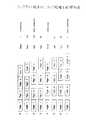
図4は、上記シップライン設定セットアップ処理の一例を示す図である。
同図は、flight1,flight2 ,flight3 ,及びflight4 の4便を接続したシップラインの切断(セグメンテーション)の例であり、「0」〜「7」の番号で識別される8種類の切断方法が示されている。同図において、“illegal ”が制約違反の切断を示している。したがって、「0」と「4」の切断が制約違反に該当する。
【0080】
制約違反でない切断については、“point ”で示された評価値が設定されており、例えば、「2」の切断に対しては、最高の評価値“500”が設定されている。また、「7」の切断に対しては、最低の評価値“1”が設定されている。制約違反を起こしていない6種類のセグメンテーションについて、その評価値に応じて、セグメンテーション確率テーブルが作成される。このセグメンテーション確率テーブルの作成方法については後述する。
【0081】
以下に、最適化部22の動作を簡単に説明する。
〔1〕 クルー・ペアリングモデル計算部22bは、GA実行部22aから入力される染色体集団2の個々の個体をデコードし、問題(クルー・ペアリングモデル)のパラメータに変換する。尚、ここでは、個体と表現しているが、これは図1の染色体2−1(個体の表現型)に該当するものである。
【0082】
〔2〕 クルー・ペアリングモデル計算部22bは、〔1〕で得られた第1のパラメータと前記セグメンテーション確率テーブルを用いて、シップライン切断(セグメント)を設定する。
【0083】
〔3〕 クルー・ペアリングモデル計算部22bは、各セグメントの割り付け順位を、〔1〕で得られた第2のパラメータにしたがって決定する。
〔4〕 クルー・ペアリングモデル計算部22bは、セグメントの後端の便について、次の接続情報(セグメント接続確率テーブル)を設定する。
【0084】
〔5〕 クルー・ペアリングモデル計算部22bは、
(a) セグメントを、〔3〕で得られた割り付け順位に従って順番に取り出し、それらのセグメントを、〔1〕で得られた第3のパラメータまたは[4〕で得られたセグメント接続確率テーブルに従って接続する。
【0085】
(b) セグメントを接続する際に、その接続が制約違反を起こしていないかチェックする。
(c) 制約違反を起こしていた場合は、(a)で接続したセグメントを取り除き、新たなセグメントを接続するために(a)に戻る。
【0086】
(d) 予め設定した条件を満足する解が生成されるまで、(a)〜(c)の処理を繰り返す。
〔6〕 クルー・ペアリングモデル計算部22bは、〔5〕で生成された解について、その適応度を計算する。
【0087】
〔7〕 上記解と上記適応度を、GA実行部22aに返す。
〔8〕 GA実行部22aは、クルー・ペアリングモデル計算部22bから、全ての個体(染色体2−1)の解と適応度を入力すると、遺伝的アルゴリズムにより、染色体集団2の世代交代を行う。
【0088】
〔9〕 クルー・ペアリングモデル計算部22bは、この世代交代により得られた個体(染色体2−1)について、〔1〕〜〔7〕を繰り返し、最適解または準最適解を生成する。
【0089】
〔10〕 最適化部22は、上記最適解または上記準最適解を、クルー・ペアリング・エディタ12に出力する。
図5は、本実施形態で使用する制約条件の事例を示す図である。本実施形態で作成する乗務パターンは、同図に示された、「乗務便数」(4便以下)、「乗務時間」(6時間以上)、「勤務時間」(11時間以下)、「乗務前準備時間」(60分)、「乗務後整理時間」(30分)、「日中の乗換え時間」(90分以上)、「宿泊禁止空港」(空港名を指定)、「基地比率」(東京60%:大阪40%)、「基地空港」(空港名を指定)、「連続勤務日数上限」(3日)、「固定パターン指定」(便のリストで指定)等の制約条件を満足しなければならない。
【0090】
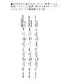
図6は、シップラインの具体例を示す図である。
シップライン(Ship line )1〜3は、以下のようになっており、全て、4つの便を連結したものとなっている。
【0091】
シップライン1:HND(羽田)→ITM(伊丹)→SPK(札幌)→ITM(伊丹)→HND(羽田)
シップライン2:SPK(札幌)→TOY(富山)→HND(羽田)→KMO(熊本)→SPK(札幌)
シップライン3:SPK(札幌)→TOY(富山)→羽田(HND)→広島(HIJ)→SPK(札幌)
図6の各シップライン1〜3の各便に付与されたf1〜f12は便名である。また、シップライン1は連日(through days)運航する便となっているが、シップライン2は奇数日のみ運航する期割れ便、シップライン3は偶数日のみ運航する期割れ便となっている。同図の左端に示すビット列は、運航日程(operating days) を示すものであり、各ビットが1日に対応している。そして、“1”のビット値が運航を、“0”のビット値が非運航を示している。
【0092】
ところで、便は「通月便」と「期割れ便」に分類される。通月(regular) 便は、スケジュール期間中、連日運航する便である。期割れ(irregular) 便は、スケジュール期間中、連日運航しない不規則な便である。
【0093】
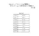
次に、図7を参照して、図6の各シップライン(Ship line )1〜3のセグメント接続確率テーブルの作成方法の一例を説明する。ここでは、理解を容易なものとするために、1日の乗務便数は「2」という制約条件が設定されているものとする。また、以下のような加点のルールを定める。この加点ルールはヒューリスティクスに定めたものである。
【0094】
・ シップラインが2つに分かれたら100点
・ シップラインが3つに分かれたら20点
・ シップラインが4つに分かれたら0点
・ HAD,ITMで切断されたら10点
・ SPKで切断されたら5点
図7に、上記規則に従って、シップライン1〜3の各切断(セグメンテーション)に付けた点数(point )を示す。同図(a)〜(c)が、それぞれ、シップライン1〜3に対応している。シップライン1〜3のいずれにおいても、5種類の切断(○印が右側に付与された切断)が制約条件を満足している。
【0095】
各シップラインについて、制約条件を満足する切断を、その点数に応じて、予め設定された幅(図7の例の場合は0〜256)にマッピングして、セグメンテーション確率テーブル30a〜30bを作成する。
【0096】
図7に示す例では、点数の高いセグメンテーション(Segmentation) から順に、セグメンテーション確率テーブル30a〜30cに登録するようにしている。また、各セグメントの登録数は点数に比例配分したものとなっている。したがって、セグメンテーション確率テーブル30a〜30cにおいては、点数の高いセグメント程、選択される確率が高くなる。よって、遺伝子のセグメントメント探索値(セグメンテーション情報)が0〜256まで無作為に選ばれる場合、各シップライン1〜3について,セグメンテーション確率テーブル30a〜30cを参照してセグメントを選択すれば、適切なセグメント選択が実現できる。尚、図7のセグメンテーション(Segmentation) においては、制約条件として、最大離陸数=2、最大飛行時間=180分、最大労働時間=360分が設定されている。なお、図7のセグメンテーション確率テーブル30a〜30cのセグメンテーションの格納方法は,あくまでも一例であり、その格納方法には各種形態が考えられる。
【0097】
図8は、シップライン1のセグメンテーション情報S10〜S17を表現するデータ構造の一例を示す図である。セグメンテーションS10〜S17は3ビットのビット列で表され、先頭のビットがf1とf2を、2番目のビットがf2とf3を、3番目のビットがf3とf4を切断するか否かを示す。これらのビットが“1”であれば切断を、“0”であれば非切断を示す。
【0098】
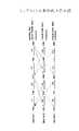
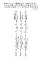
図9は、本実施形態で使用する染色体2−1の構成例を示す図である。
同図に示す染色体40は、図6のシップライン1〜3から、乗務パターンを作成するためのものである。染色体40は、便1(f1)〜便12(f12)の割り付け順序情報を格納する遺伝子41、各シップライン1〜3のセグメンテーション情報を格納している遺伝子42、及び各便1(f1)〜便12(f12)について接続候補便情報(接続候補リスト)を格納している遺伝子43(43−1〜43−12)から構成されている。
【0099】
この染色体40は、遺伝子42、遺伝子41、遺伝子43の順にデコードされる。遺伝子42は3個の整数型のデータの配列であり、順に、シップライン1(sl1 )、シップライン2(sl2 )、及びシップライン3(sl3 )の各シップラインのセグメンテーション(segmentation) 情報〔整数値〕を格納している。この遺伝子42の各シップライン1、シップライン2、及びシップライン3の各整数値は、それぞれ、上述したセグメンテーション確率テーブル30a,30b,30cのアドレス値である。
【0100】
遺伝子42の各シップライン1〜3に割り当てられた値は、シップライン1、2、3の順に、個別にデコードされる。このデコードの際、各シップラインの割当値は、対応するセグメンテーション確率テーブルのアドレスを示すポインタとして使用され、該アドレスからセグメンテーション情報を取得するために利用される。
【0101】
上述したように、セグメンテーション確率テーブル30a,b,cには、有効な(illegal)なセグメンテーション情報が格納されている。したがって、遺伝子42をデコードすることにより、各シップライン1〜3のセグメンテーション情報を取得できる。そして、このセグメンテーション情報を基に、各シップライン1〜シップライン3について、1または複数のセグメントが得られる。該セグメントは、上述したように、1便または複数の便の接続であり、各セグメントは先頭の便(最初に出発する便)と最後の便(最後に到着する便)よって規定される。
【0102】
このようにして得られた各セグメントから、まず、先頭の便が取得される。この取得された先頭の便は、遺伝子41のデコードに利用される。遺伝子41は12個の整数型のデータの配列であり、便1(f1)〜便12(f12)の順に、割り付け順序情報を格納している。上述した遺伝子42のデコード処理の結果、上記先頭の便に該当する便のみが有効便として抽出され、その有効便が遺伝子41の対応値に従ってソートされる(遺伝子41の整数値が小さい有効便から順にソートされる)。このソートの結果、まず、先頭にソートされた便が先頭の便となっているセグメントを先頭する乗務パターンの作成が開始される。また、上記有効便を先頭の便とするセグメントの後尾の便についてセグメント接続確率テーブルが作成される。このセグメント接続確率テーブルは、後述するように乗務パターンを作成する際のセグメント接続に利用される。
【0103】
遺伝子43は、便1〜便12の各便に対応する12個の配列43(43−1〜43−12)を有し、各配列43には、各便の接続候補リストが格納されている。各配列43の要素は便の識別子を示す整数値である。この遺伝子43は、乗務パターンのセグメント接続に利用される。すなわち、該セグメント接続の際、配列43から配列順に(接続候補リストのリスト順に)、配列要素(接続候補となるセグメントの先頭の便)を取り出し、それまでに作成されている乗務パターンにそのセグメントを接続する。そして、このセグメント接続が制約違反であるか判断される。
【0104】
そして、制約違反である場合には、そのセグメントの接続は破棄され、配列43から次のセグメントが選択される。一方、該セグメント接続が制約違反でない場合は、乗務パターンの作成は続行される。また、各配列43−1〜43−12の要素数(接続候補便数)は、各便毎に可変であり、最終要素の後には“−1”(強制終了)が設定される。
【0105】
次に、本実施形態の全体動作を図10のフローチャートを参照しながら説明する。同図において、ステップS21〜S25がプリプロセッサ21が実行するプリプロセス処理を示している。
【0106】
まず、プリプロセッサ21がファイル13から制約条件、GAパラメータ等を読み込み、それらをメモリ(不図示)上に展開する(ステップS21)。
該GAパラメータは、例えば、染色体集団2の染色体2−1の個数、選択操作器1−2の選択操作率、交叉操作器1−3の交叉率、及び突然変異操作器1−4の突然変異率等である。
【0107】
次に、プリプロセッサ21はファイル14から便データを一式読み込み、それを該メモリ上に展開する(ステップS22)。
続いて、上記ファイル14から読み込んだ便データを基に、便接続を調べ、各乗務便について後述する接続テーブルを作成する(ステップS23)。
【0108】
次に、上記ファイル13から読み込んだ情報を基に、シップラインを抽出し、各シップラインについて図7に示すようなセグメンテーション確率テーブルを作成する(ステップS24)。
【0109】
続いて、ステップS21で読み込んだGAパラメータの計算を行い、GA22aを構築する(ステップS25)。以上の処理により、プリプロセス処理が終了する。
【0110】
次に、最適化部22が図2のフローチャートに示すアルゴリズムを実行し、GA実行部22aとクルー・ペアリングモデル計算部22bを駆使しながら、問題の解の探索を行う(ステップS26)。クルー・ペアリングモデル計算部22bは、GA探索器4−3、局所探索手法器4−2、または確率的探索器4−4により解の探索を行う。
【0111】
局所探索手法器4−2においては、例えば以下のような処理を行う。
例1) 連日運航する通月便に対して、偶数日に運航する期割れ便(01010101の乗務パターン)を割り当てた後に、それを補完する奇数日に運航する期割れ便(10101010の乗務パターン)を探して、それを上記通月便の残りの運航日に割り当てる処理を行う。
【0112】
例2) 乗務パターンの開始が期割れ便であった場合に、それを補完する期割れ便が無く、かつ、最初の乗務パターンの2日目が基地からデッドアヘッドで接続できる場合、そのようなパターンを生成する。
【0113】
また、各染色体2−1の適応度(評価値)は、例えば、以下の式により設定する。
適応度=α・(乗務パターンに組み込まれていない便数)+β・(乗務パターン数)+γ・(移動費用)+δ・(基地比率からの逸脱)+・・・
上記比例定数α、β、γ、δ等は、例えば実験を繰り返しながら決定する。そして、作成した解に対して上記式を適用し、その適応度を算出する。尚、α、β、γ、δは正の定数である。
【0114】
ステップS26の処理は、処理の実行の中断の指令があったか、指定回数の探索を終了したか、または指定の条件を満足する解が得られたかのいずれかの判断がなされるまで(ステップS27)、クルー・ペアリングモデル計算部22b内のセグメント接続コントローラ(図1のコントーラ4−1に相当)の制御により、繰り返し行われる。
【0115】
そして、ステップS27で、セグメント接続コントローラにより上記いずれかの判断がなされると(ステップS27,Yes)、クルー・ペアリングモデル計算部22bは、それまでに得られた解(最良の解等)をクルー・ペアリング・エディタ11に出力する(ステップS28)。
【0116】
図11及び図12は、ステップS23で作成される接続テーブルのデータ構造を示す図である。
図11は、接続テーブルの全体構成を示す図である。
【0117】
同図に示すように、接続テーブル50は、「対象の便情報50a」、「同一機材の次接続の便情報50b」、「当日乗換便情報50c」、「当日デッドヘッド情報50d」、「翌日の乗務便情報50e」、「翌日乗換便情報50f」、「翌日デッドヘッド情報50g」、「セグメント接続テーブル50h」、「基地空港からの出発情報50i」、及び「基地空港への到着情報50j」から成る。
【0118】
図12は、上記情報50a〜50jの内、セグメント接続テーブル50h以外の情報のデータ構造を示す図である。
同図に示すように、これらの情報は、「便名60a」、「機材番号60b」、「出発空港60c」、「出発時刻60d」、「到着空港60e」、「到着時刻60f」、「運航パターン60g」、及び「乗務時間60h」の各フィールドから構成されるレコード60として、接続テーブル50に格納される。運航パターン60gは、例えば、一ヵ月の運航日程を示す31ビットの2値のビット列で構成される。この場合、“1”が運航日を、“0”が非運航日を示す。
【0119】
図13は、本実施形態の最適化部22による解の生成処理(複数の乗務パターンの作成処理)の全体フローを説明する図である。尚、このフローチャートは、一つの染色体2−1(染色体40)による解の生成処理を説明するフローチャートである。
【0120】
まず、染色体40の遺伝子43の各シップラインのセグメンテーション情報について、それぞれに対応するセグメンテーション確率テーブルを用いてデコードする(ステップS41)。これにより、遺伝子43に登録された各シップラインが、そのセグメンテーション情報に応じて、1または複数のセグメントに分割される。
【0121】
次に、ステップS41で得られた各セグメントの先頭の便の遺伝子41の値を参照し、上述した先頭の便のソート処理を行い、セグメントの割り付け順を設定する(ステップS42)。すなわち、ソート順位の高い先頭便を有するセグメント程、割り付け順位を高く設定する。
【0122】
例えば、染色体40の場合、遺伝子42による各シップライン1(sl1) 〜3(sl3) のセグメント分割により、図6のシップライン1〜3が、図14で破線で示すようにセグメント分割されたとする。すなわち、シップライン1がセグメントS1とS2に、シップライン2がセグメントS3とS4に、シップライン3がセグメントS5とS6に分割されたとする。この結果、遺伝子41が参照されて、図15に示すようなソート結果(f1,f3,f7,f5,f11,f)が得られる。そして、最終的に、図16に示すようにセグメントの割り付け順位(S1,S2,S4,S3,S6,S5)が設定される。
【0123】
続いて、セグメント接続を開始するにあたって、上記各セグメントの後尾の便の接続情報を処理する。この処理は、セグメントの先頭に位置していない接続(便)を除去する処理である(ステップS43)。以上のようにして、有効な接続便が求まる。例えば、図7(a)に示すシップライン1が、セグメンテーションS12で切断された場合、有効な接続便はf2とf4となる。
【0124】
次に、ステップS43で得られた有効な接続便の全てに対して、個々に、セグメント接続確率テーブル(Segment 接続確率テーブル) を作成する(ステップS44)。
【0125】
図17は、上述したように、図7(a)にシップライン1が、セグメンテーションS12で切断された場合における、有効な接続便f2に関するセグメント接続確率テーブルの例を示す図である。
【0126】
同図に示す、f2に関するセグメント接続確率テーブル70は、f3、f5,f9との接続確率、f5→f6,f5→f10,f9→f6,及びf9→f10との接続確率を示している。この場合、f3は、当日デッドヘッド後に当日乗務は行わない接続である(接続確率は、0.20)。また、f3及びf5は、翌日乗務の接続である(接続確率は、それぞれ、0.30,0.20)。また、さらに、f5→f6,f5→f10,f9→f6,及びf9→f10は、翌日デッドヘッド後に翌日乗務を行う接続である(接続確率は、それぞれ、0.10,0.05,0.05,及び0.10)。尚、このステップS44のセグメント接続確率テーブルの作成は、プリプロセス処理で得られたセグメント接続確率テーブル50hや既に作成されている乗務パターン等を基にして行われる,セグメント接続確率テーブルの再構成処理である。
【0127】
以上のようにして、GA実行部22aのデコード処理部3によるステップS41〜S44のデコード処理が行われる。
次に、クルー・ペアリングモデル計算部22bによる解の生成処理が開始される。
【0128】
この場合、まず、クルー・ペアリングモデル計算部22b内部に設けられたセグメント接続コントローラ(不図示)が、ステップS42で得られたセグメントの割り付け順位結果に従って、先頭のセグメントを取り出し、このセグメントを先頭とする乗務パターンの作成を開始する。また、セグメント接続コントローラは、以下に示す判断基準にしたがって、ステップS46〜48の3つのステップSのいすれかの処理を実行する。
【0129】
▲1▼ もし、通月(regular)のセグメントが期割れになったらステップS46 で局所探索によりセグメント(Segment)を繋ぐ。
▲2▼ 現在、処理対象のセグメントの遺伝子43に、まだ、未使用で、かつ、まだ乗務パターンに組み込まれていない接続候補便情報があれば、ステップS47で、その接続候補便情報に従って、セグメントを繋ぐ。
【0130】
▲3▼ 現在、処理対象のセグメントの遺伝子43で使用可能な接続候補便情報が無くなれば、ステップS48で、ステップS44で作成したセグメント接続確率テーブルを用いて、セグメントを繋ぐ。
【0131】
セグメント接続確率テーブルは、▲1▼〜▲3▼の順に、順に判断して、実行すべきステップを決定する。
ステップS46では、局所探索手法器4−2が未接続のセグメントの中から、現時点の乗務パターンの後尾の便に接続するのに最適なセグメントを、局所探索により探索し、そのセグメントを、該乗務パターンの最後尾の便に繋げる。
【0132】
ステップS47では、GA探索器4−3が、現在までに作成されている乗務パターンの最後尾の便の遺伝子43の接続候補リストに従って、該最後尾の便に接続すべきセグメントを決定する。
【0133】
ステップS48では、確率的探索器4−4がステップS44で作成されたセグメント接続確率テーブルに従って、現在までに作成されている乗務パターンの最後尾の便に接続すべきセグメントを決定する。尚、このとき使用されるセグメント接続確率テーブルは、該最後尾の便のセグメント接続確率テーブルである。
【0134】
上記ステップS46〜S48のいずれかのステップの処理によって、セグメントの新たな接続が行われると、制約違反判定器4−5によって、そのセグメントの接続が制約違反器かどうかが判断される(ステップS49)。
【0135】
そして、制約違反であれば、制約違反処理器4−6がステップS46、S47,またはS48で繋いだセグメントを、現在の乗務パターンから取り除き(ステップS50)、ステップS45に戻る。
【0136】
一方、ステップS49で制約違反でないと判断されれば、乗務パターン(Crew Pattern) が完成したか判断する(ステップS51)。
乗務パターンの完成条件とは、例えば、以下のようなものである。
【0137】
▲1▼ ステップS47の遺伝子43のデコードで“−1”(強制終了)がデコードされたとき。
▲2▼ 乗務パターンの終端の便で、当日に、基地空港に帰還可能である確率が95%である。
【0138】
ステップS51で、乗務パターンが完成していないと判断した場合は、ステップS45に戻り、次のセグメントの接続処理に進む。
一方、ステップS51で、乗務パターンが完成したと判断すれば、該乗務パターンを解の一部として登録する等の終端処理を行い、次の乗務パターンの作成処理に移行するために、ステップS45に戻る。
【0139】
以上のようにして、ステップS45〜S52のループ処理が繰り返されることにより、次々に複数の乗務パターンが作成され、解が作成されていく。そして、ステップS45で、セグメント接続コントローラは、処理の終了を判断すると、それまでに得られた解を解・適応度算出器4−7に出力し、処理の実行権を解・適応度算出器4−7に委譲する。
【0140】
解・適応度算出器4−7は、セグメント接続確率テーブルから受け取った解の適応度を算出し(ステップS51)、今回の処理で使用した染色体2−1(染色体40)の解2−2と適応度2−3を染色体集団2に出力し(ステップS52)、処理を終了する。
【0141】
図18〜図22は、図13のフローチャートの処理の実行による乗務パターン作成(解2−2の作成)の手順を具体的に説明する図である。
以下の説明では、図18に示すシップライン(Ship line) 1〜3について乗務パターンを作成する例について説明する。尚、図18は、上述した図6に示すシップライン1〜3と同一なので、ここでは、各シップラインの構成などの詳しい説明は省略する。
【0142】
まず、全てのシップライン1〜3が、染色体40の遺伝子42のデコードにより、それぞれに対応する図7(a)〜(c)に示すセグメンテーション確率テーブル30a〜30cを参照して、図19に示すようにセグメント分割されたとする。すなわち、シップライン1は、便f1と便f2を接続するセグメントS1と、便f3と便f4を接続するセグメントS2に分割されたとする。同様にして、図19に示すように、シップライン2は、便f5と便f6を接続するセグメントS3と、便f7と便f8を接続するセグメントS4に分割され、シップライン3は、便f9と便f10を接続するセグメントS5と、便f11と便f12を接続するセグメントS6に分割されたとする。
【0143】
次に、遺伝子41のデコードの結果により、セグメント接続コントローラにより、セグメントS1を先頭とする乗務パターンの作成が開始される(図16参照)。図9では図示していないが、セグメントS1の後尾の便f2の遺伝子43(43−2)に最初の接続候補便として、セグメントS5の先頭の便f9が指定されていたとする。これにより、セグメントS1とセグメントS5を図21の実線の矢印1のように接続する(ステップS47)。このセグメント接続が制約違反でないとすると、セグメントS5は基準空港(HND)に到着する便f10が終端の便となっているので、まず、第1の乗務パターン(S1→S5)の作成が終了する。この結果、セグメントS5は奇数日の期割れ(0101010101)なので、セグメントS1の残りの運航は偶数日の期割れとなる。
【0144】
次に、上記期割れにより、局所探索手法器4−2により局所探索が開始され、セグメントS1の接続先として、偶数日の期割れとなっているセグメントS3が見つけ出されたとする(ステップS46)。これにより、セグメントS1とセグメントS3を図21の破線の矢印2のように接続する。このセグメント接続が制約違反でないとすると、セグメントS3は基準空港(HND)に到着する便f6が終端の便となっているので、図20の破線の矢印2に示すような第2の乗務パターン(S1→S3)が作成される。
【0145】
以上の処理により、セグメントS1の運航日は全て、上記第1及び第2の乗務パターンに組み込まれたので、セグメントS1を先頭とする乗務パターンの作成処理は、終了する。
【0146】
次に、セグメント接続コントローラは、図16に示すセグメント割り付け順に従って、セグメントS2を先頭とする乗務パターンの作成を開始させる。
すると、セグメントS2は基地空港(この場合、基地空港には、HND(羽田)だけが指定されているとする)からのデッドヘッドがないため、先頭とはなれず、次の先頭となるセグメントの検索処理に進む。
【0147】
この結果、図16に示す割り付け順に従って、次の先頭セグメントはセグメントS4となる。この時点で、セグメントS4に接続可能な残りのセグメントはセグメントS2なので、図21の実線の矢印3に示すように,セグメントS4とセグメントS2を図21の実線の矢印3のように接続する(ステップS46)。このセグメント接続が制約違反でないとすると、セグメントS2は基準空港(HND)に到着する便f4が終端の便となっているので、図21の実線の矢印3に示すような第3の乗務パターン(S4→S2)が作成される。
【0148】
この第3の乗務パターンの作成により、セグメントS2の残りの運航は偶数日に運航する期割れとなるので、セグメント接続コントローラにより、局所探索手法器4−2が起動され、局所探索により、期割れとなったセグメントS2を補完するセグメントが探索される。これにより、セグメントS2に接続するセグメントとして、セグメントS2と同様なパターンの偶数日に運航する期割れとなっているセグメント6が探索され、図21の実線の矢印3に示すように,セグメントS2とセグメントS6を図21の破線の矢印3のように接続する(ステップS46)。このセグメント接続が制約違反でないとすると、セグメントS6は基準空港(HND)に到着する便f12が終端の便となっているので、図21の破線の矢印4で示される第4の乗務パターン(S6→S2)が作成される。
【0149】
以上の処理により、セグメントS2の運航日は全て、上記第3及び第4の乗務パターンに組み込まれたので、セグメントS2を先頭とする乗務パターンの作成処理は、終了する。
【0150】
この結果、全てのセグメントS1〜S6の全ての運航日が、第1〜第4の乗務パターンに組み込まれたので、乗務パターン生成のプロセスは全て終了する。
尚、図19〜図20に示す例では、確率的探索器4−4が利用されていないが、局所探索手法器4−2及びGA探索器4−3のいずれでも、適切なセグメントを探索できない場合には、セグメント接続コントローラにより確率的探索器4−4が起動され、確率的探索器4−4によりセグメント接続が実行される。
【0151】
尚、上記実施形態は、本発明を乗務パターン作成装置に適用した例であるが、本発明は、これに限定されることなく、制約充足最適化問題等を解く最適化装置全てに適用可能である。
【0152】
図22は、本発明の実施形態を実現するコンピュータのハードウェア構成を示す図である。
同図において、CPU101は、バス109を介して、ROM102、RAM103、外部記憶装置104、記録媒体駆動装置105、入出力装置107,及び通信インターフェース108と接続されている。
【0153】
CPU101は、ROM102に記憶されたプログラム及びRAM103にロードされたプログラムを実行することにより、上述した本実施形態の最適化装置の機能を実現する。外部記憶装置104は、RAM103にロードされる上記プログラム、上記ファイル13、14等を記憶する。
【0154】
外部記憶装置104は、例えば、磁気ディスク装置、光磁気ディスク装置等である。記録媒体駆動装置105は、上記プログラムが記録された可搬記憶媒体106が装着される。可搬記憶媒体106に格納されているプログラムは、記録媒体駆動装置105により読み取られ、RAM103上にロードされ、CPU101により実行される。この実行により、上述した本実施形態の最適化装置の機能が実現される。
【0155】
通信インターフェース108は、ネットワーク200を介して情報提供業者300が保有する上記プログラムを、外部記憶装置104にダウンロードする。このようにしてダウンロードされたプログラムは、外部記憶装置104から読みだされてRAM103に展開されて、CPU101により実行される。この実行により、上述した本実施形態の最適化装置の機能が実現される。
【0156】
また、上記プログラムを、情報提供業者300が保有するコンピュータで遠隔実行させて、上述した本実施形態の最適化装置の機能を該コンピュータで実現されることも可能である。このような形態の場合、解は、通信インターフェース108を介して、コンピュータ100に受信され、入出力装置107を介して出力されることになる。
【0157】
入出力装置107は、ユーザに、GUI等を介して、外部記憶装置104等に格納されている制約条件エディタ11、クルー・ペアリング・エディタ12をCPU101に実行させる環境を提供する。そして、ユーザに、これらのエディタ11、12を利用して、ファイル13、14を作成・編集させる。また、入出力装置107は、上記プログラムの実行により得られた解等を出力(表示・印字等)する。
【0158】
可搬記憶媒体106は、磁気ディスク、光ディスク、光磁気ディスク、CD(Compact Disc)、DVD(Digital Versatile Disc) ,PCカード等である。
ネットワーク200は、インターネット、イントラネット、エクストラネット、VPN(Virtual Private Network)、公衆回線、専用回線、衛星回線、CATV(CAble TeleVision)回線、LAN,MAN,WAN等である。
【0159】
【発明の効果】
以上、説明したように、本発明によれば、以下のような効果が得られる。
1) 従来技術では全く扱うことができなかった、不定期な業務を含む長期間に渡るモデル(Fully Dated Model)での計画を処理することが可能になる。
2) 個々の処理に必要な前処理、後処理を、解生成の段階で問題モデルが自動的に付与するため、航空機の乗務パターンの作成に適用した場合、デッドヘッド(dead head )等の取扱が一元的に可能になる。
3) 広範囲な探索空間を持つ問題を、効率的に探索可能になり、探索時間を大幅に減少させることが可能になる。また、ヒューリスティクス、確率的探索、ルールに基づく探索がバランス良く実現でき、制約条件が多い組み合わせ問題についても、質の良い解を短時間に導出できるようになる。。
4) 航空の乗務スケジュールの作成に適用した場合、従来、数年間の実務経験を積んだ専門家が、人手で一週間程度かけていたスケジュール作成を、半日程度で自動的に作成できるようになった。
【図面の簡単な説明】
【図1】本発明の原理構成図である。
【図2】本発明の原理を説明するフローチャートである。
【図3】本発明の実施形態の全体システム構成を示すブロック図である。
【図4】シップライン設定セットアップ処理を説明する図である。
【図5】本実施形態で使用する制約条件の事例を示す図である。
【図6】シップラインの具体例を示す図である。
【図7】図6の各シップラインのセグメンテーション確率テーブルの作成方法を説明する図である。
【図8】」図6のシップライン1の8種類のセグメンテーションを表現するデータ構造を示す図である。
【図9】本実施形態で使用する染色体のデータ構造の一例を示す図である。
【図10】本実施形態の全体動作を説明するフローチャートである。
【図11】プリプロセス処理で作成する接続テーブルのデータ構造を示す図である。
【図12】図12のセグメント接続確率テーブル以外のレコードのデータ構造を示す図である。
【図13】本実施形態による、染色体を用いた解の生成処理を説明するフローチャートである。
【図14】シップライン1〜3の一例を示す図である。
【図15】図15のシップライン1〜3について、図9の染色体をデコードすることにより得られるセグメントの先頭便のソート結果を示す図である。
【図16】図16のソート結果を基にして得られる、セグメントの割り付け順位を示す図である。
【図17】図13のフローチャートの染色体のデコード処理で生成される、有効な接続の便のセグメント接続確率テーブルのデータ構造の一例を示す図である。
【図18】シップライン1〜3の具体例を示す図である。
【図19】図9の染色体を、図7のセグメンテーション確率テーブルを利用してデコードした結果、得られる図18のシップライン1〜3のセグメント分割結果を示す図である。
【図20】図19のセグメント分割結果に対して、図9の染色体のデコード結果と局所探索手法を適用して、第1及び第2の乗務パターンを作成する手順を説明する図である。
【図21】図20に示された処理の後に、図9の染色体のデコード結果と局所探索手法を適用して、第3及び第4の乗務パターンを作成する手順を説明する図である。
【図22】本実施形態を実現するコンピュータのハードウェア構成の一例を示す図である。
【符号の説明】
1 GA処理部
1−1 適応度計算器
1−2 選択操作器
1−3 交叉操作器
1−4 突然変異操作器
2 染色体集団
2−1 染色体
2−2 解
2−3 適応度
3 デコード処理部
3−1 問題のパラメータ
4 問題モデル計算部
4−1 コントローラ
4−2 局所探索手法器
4−3 GA探索器
4−4 確率的探索器
4−5 制約違反判定器
4−6 制約違反処理器
4−7 解・適応度算出器
10 GUI(グラフィカル・ユーザ・インタフェース)装置
11 制約条件エディタ
12 クルー・ペアリング・エディタ
13 制約条件等を格納するファイル
14 便データを格納するファイル
20 GAクルー・ペアリング・最適化装置
21 プリプロセッサ
22 最適化部
22a GA実行部
22b クルー・ペアリングモデル計算部
30a シップライン1用のセグメンテーション確率テーブル
30b シップライン2用のセグメンテーション確率テーブル
30c シップライン3用のセグメンテーション確率テーブル
40 染色体
41 各便1〜便12の割り付け順序情報を格納する遺伝子
42 セグメンテーション1〜3のセグメンテーション情報を格納している遺伝子
43 便1〜便12の接続候補リストを格納している遺伝子
50 プリプロセス処理で作成される接続テーブルのデータ構造
50a 対象の便情報
50b 同一機材の次接続便情報
50c 当日乗換便情報
50d 当日デッドヘッド情報
50e 翌日の乗務便情報
50f 翌日の乗換便情報
50g 翌日デッドヘッド情報
50h セグメント接続確率テーブル
50i 基地空港からの出発情報
50j 基地空港への到着情報
60 50a〜50g及び50i,50jのデータ構造
70 セグメント接続確率テーブル
100 コンピュータ
101 CPU
102 ROM
103 RAM
104 外部記憶装置
105 記録媒体駆動装置
106 可搬記録媒体
107 入出力装置
108 通信インターフェース
200 ネットワーク
300 情報提供業者[0001]
BACKGROUND OF THE INVENTION
The present inventionOptimization device About.
[0002]
[Prior art]
Optimization forms the basis of intelligent processing in advanced computer utilization, and has specific application fields such as scheduling problems, dispatch planning problems, pattern estimation, automatic time allocation, and occupant placement problems. However, it is not realistic to solve such a large-scale optimization problem directly by searching for all solutions because of the amount of calculation and the storage capacity of the storage device.
[0003]
As computer performance has improved in recent years, stochastic optimization methods (simulated annealing, GA (genetic algorithm)) have attracted attention as a means of solving problems that were difficult to solve with conventional expert systems. Abi, research for its practical use has been made. Among various optimization methods, GA is attracting attention because of its simplicity.
[0004]
In all industries, personnel scheduling is a fundamental problem, which can be considered as one of optimization problems. This problem has a decisive impact on cost reduction in all industrial sectors.
[0005]
For example, in the aviation field, it is said that labor costs are the second largest after fuel costs, and reducing labor costs is a major issue.
As a general method for solving the combination problem, modeling using simultaneous equations and mathematical solution such as LP (Linear Progrming) and IP (Integere Programming) are used, and the problem is solved as a Set Partitioning or Set Covering problem.
[0006]
However, these methods are difficult to formulate when solving complex problems.For example, even if it can be formulated, large-scale problems will increase the definition and the number of combinations, and will be solved within a practical time frame. I can't get it. In addition, there is a problem that no solution is found after all hours.
[0007]
Also, column generation and other methods are used for speeding up, but due to problems such as column generation time and memory capacity limitations, large-scale problems face various limitations.
[0008]
GA (Genetic Algorithms) has attracted attention as a means for solving such a conventional method. In GA, the problem is modeled and its parameters are expressed in chromosomes. When optimizing with GA, a chromosome is decoded and converted into a parameter, the parameter is input into a problem model, the evaluation is performed, and the evaluation value is used as the fitness of the chromosome. ) And advance optimization.
[0009]
[Problems to be solved by the invention]
1. Problem descriptiveness problem
In IP / LP, a description of a problem must be expressed in the form of a matrix. With this method, it is difficult to reflect individual conditions in detail.
[0010]
One method of solving with column generation is to rule the problem and describe the details of the problem as a generation rule at the time of column generation, but how to express the problem with the rule, the completeness and validity of the rule It has various problems such as verification and ensuring consistency between rules.
2. Problems with search methods
Even with a GA that has advantages not found in conventional methods, the following limitations are also imposed on the solution seeking ability when the solution space becomes enormous.
[0011]
1) The GA chromosome cannot cover the entire solution space.
2) If coding is performed so as to cover the solution space uniformly, there will be a large number of areas where there are constraint violations and areas that are inappropriate as solutions, and optimization cannot be performed efficiently.
[0012]
3) Although it may be desirable to generate a solution using a solution generation rule, if a solution is simply generated using only the rule, the solution finding method becomes rigid and a high-quality solution cannot be obtained.
3. Schedule period and regularity of work
The target that actually needs to be scheduled is quite complicated with or without specific work depending on the day, but it is difficult to handle this directly with conventional methods, so the same work is done every day. Assuming that it will continue, we have a schedule for several days. This is called Daily Model.
[0013]
Since the work to be scheduled becomes more and more irregular in the future, solutions such as the Daily Model are increasingly non-substantial scheduling.
[0014]
By the way, there may be a case where there is no work on the weekend only, such as the US flight crew schedule, and this is called a Weekly Model.
Furthermore, a case in which all irregular schedule targets are taken and the schedule period is about 1 to 2 months is called a Full Date Model, and an example in which this is directly handled is not known.
[0015]
The object of the present invention is to automatically generate a solution for a constraint satisfaction optimization problem having a wide search space and a large number of constraint conditions, such as a Fully Dated Model, where it was impossible to obtain a solution in the past. NaOptimization device Is to realize.
[0016]
[Means for Solving the Problems]
The optimization apparatus of the present invention comprises the following means.
The solution data presentation meansExpressed as a chromosome determined by a genetic algorithm The solution dataProblem model The evaluation value of the solution obtained as a result of applicationAs the fitness of the chromosome ReceiveEvolving the chromosomes by genetic algorithms As a result, optimization of the solution data is advanced.
[0017]
The solicitation means is based on the solicitation data received from the solicitation data presentation means.Small The solution of the problem model is obtained by using the local search method and the probabilistic search method at least.
[0018]
The evaluation value calculation means calculates the evaluation value of the solution obtained by the solution finding means, and outputs it to the solution finding presentation means.
The solution acquisition unit controls the solution-finding data presenting unit, the solution finding unit, and the evaluation value calculating unit to obtain a final solution of the problem model.
[0022]
The problem model is,Ah Constraint Satisfaction Optimum for finding a solution of a second schedule that spans multiple days obtained by connecting a plurality of first schedules consisting of a series of operations in units of one day across multiple days A model of the problemis there .
[0023]
In such a configuration, the work isVoyage In this case, the first schedule is a one-day crew pattern, and the second schedule is a crew pattern that spans multiple days. In this case, the local search method is, Period Used when searching for connected flights that can be operated on the remaining operating days of broken flights. The probabilistic search method is used to search for the next connected flight.
[0024]
Further, the solution finding means includes:Each ship using the first gene of the chromosome and a segmentation probability table provided for each shipline and storing information for probabilistically determining a division method of each shipline. By dividing the line into segments and connecting the divided segments to create a crew pattern that spans the plurality of days, the second gene of the chromosome and each of the flights provided for each flight, Using the segment connection probability table storing connection probability values related to flights to be connected to flights, the next segment to be connected is stochastically searched. .
[0028]
In such an aspect, the solution finding means includes a segment connection probability table that is provided for each flight and stores a connection probability value related to a flight to be connected to each flight, provided for each flight. Use to probabilistically search for the next segment to connect.
[0031]
DETAILED DESCRIPTION OF THE INVENTION
Hereinafter, embodiments of the present invention will be described with reference to the drawings.
FIG. 1 is a diagram for explaining the principle of an embodiment of the present invention. In FIG. 1, GA (Geneteic Algorithms) is adopted as an optimization mechanism, but the optimization mechanism of the present invention is not limited to GA.
[0032]
The
The fitness calculator 1-1 calculates the fitness of each chromosome 2-1 in the
[0033]
The crossover operator 1-3 combines two chromosomes 2-1 selected by the selection operator 1-2 at random, and partially sets the gene strings of the two chromosomes 2-1 with a certain probability (crossover rate). Replace with.
[0034]
The mutation operator 1-4 replaces the gene at each locus on the chromosome 2-1 with another allele with a certain probability (mutation rate).
The fitness calculator 1-1 replaces the N chromosomes 2-1 in the
[0035]
Chromosome 2-1 is composed of m genes (m is an arbitrary integer). The gene at each locus is represented by a character string, a bit string, an integer array, or the like. Each chromosome 2-1 has a solution 2-2 and a fitness 2-3. The solution 2-1 is a solution of the problem generated when the chromosome 2-1 converted into the parameter of the problem model in the problem
[0036]
The
[0037]
The problem
[0038]
The problem
[0039]
The controller 4-1 controls the entire problem
[0040]
An optimal solution or a suboptimal solution is obtained by repeatedly performing the processing of the local search method device 4-2, the GA search device 4-3, or the probabilistic search device 4-4. The constraint violation determiner 4-5 determines whether or not the solution on the way does not cause a constraint violation.
[0041]
When the constraint violation determiner 4-5 determines a constraint violation, the constraint violation processor 4-6 is activated, and the local search method unit 4-2, the GA searcher 4-3, or the probabilistic searcher 4-4. A process such as removing a part of the solution added by is performed, and the process proceeds to the controller 4-1. The controller 4-1 determines whether the solution creation process has been completed. If not yet completed, the controller 4-1 performs the above-described determination, and determines the local search method device 4-2, the GA search device 4-3, or the probability. The automatic searcher 4-4 is activated.
[0042]
When the controller 4-1 determines the end of the generation of the solution while continuing the loop processing as described above, the solution / fitness calculator 4-7 receives the solution generated from the controller 4-1, and evaluates the solution. The value (fitness of chromosome 2-1) is calculated. Then, the solution / fitness calculator 4-7 returns the solution 2-2 and fitness 2-3 of the chromosome 2-1 decoded by the
[0043]
The main points of the principle of the present invention will be briefly described.
[1] When the problem parameter 3-1 obtained by the decoding of the
[0044]
The problem model in the problem
[2] The problem
[0045]
[3] The local search method unit 4-2 searches for solution candidates by the local search method. For example, in the generation of a crew pattern, when an unsatisfied flight occurs, a connection flight that complements the unscheduled flight is searched.
[0046]
[4] The GA searcher 4-3 searches for a solution candidate based on, for example, information on a part of genes of the chromosome 2-1.
[5] The probabilistic searcher 4-4 searches for a solution candidate with reference to a probability table (not shown). In the probability table, a new probability is calculated from the previously calculated probability of the solution candidate and the relationship between the solution generated so far and the solution candidate, and a solution candidate is presented according to this probability. What is presented as a solution candidate from the probability table includes not only simple probabilities but also those tailored to the nature of the problem.
[0047]
The probabilistic searcher 4-4 is activated, for example, when the processing by the GA searcher 4-3 becomes impossible.
[6] After the final generation of the solution is completed by the problem
[0048]
[7] [1] to [6] are performed on all chromosomes 2-1 in the
[0049]
FIG. 2 is a flowchart for explaining a processing algorithm of the optimization apparatus of FIG. This flowchart is a flowchart for one chromosome 2-1.
[0050]
First, the
[0051]
Next, the problem
[0052]
The solution generation processing includes “solution addition processing according to GA searcher 4-3” (step S4), “solution addition processing using probabilistic searcher 4-4” (step S5), and “localization processing”. It includes any one of “addition processing of solution by search method device 4-2” (step S6).
[0053]
The solution generated by the process of step S4, S5, or S6 is determined by the constraint violation determiner 4-1 whether or not the constraint condition is satisfied (step S7). If it is determined in step S7 that the constraint condition is satisfied, the process returns to step S3, and it is determined in step S3 whether the solution generation process continues or ends.
[0054]
On the other hand, if it is determined in step S7 that the solution generated in step S4, S5 or S6 has caused a constraint violation, the portion added in step S4, S5 or S6 is removed from the solution (step S7). S8), the process returns to step S3, and a search is made for another solution.
[0055]
As described above, the processes in steps S3 to S8 are repeated, and when it is determined in step S3 that a solution (optimum solution or quasi-optimal solution) equal to or higher than a predetermined evaluation value is obtained, the process ends. The process is also terminated when it is difficult to continue the process. Further, the process may be terminated when a satisfactory solution cannot be obtained even when the number of searches exceeds a predetermined number.
[0056]
Next, an embodiment in which the present invention is applied to generation of a crew pattern over a long period of an aircraft crew (Crew) will be described.
Crew pattern creation is a kind of constraint satisfaction optimization problem (a problem that satisfies all the given constraints and optimizes the target evaluation index), especially for time series scheduling problems that are difficult to automate. is there.
[0057]
First, an outline of crew pattern creation work used in the present embodiment will be described.
The flight crew of the flight starts from the flight from the airport where the office is located (base airport), transfers several flights up to 4 times a day, then finishes the day's flight, Overnight at the airport. The next day, the crew starts from another flight that departs from the airport. In this way, after repeating several days of crew, we will return to the base airport of the first crew within three days. This series of flight connection patterns is referred to as a “crew pattern”. In the crew pattern creation work, it is necessary to create a plurality of crew patterns so that all flights on the diagram are included in any pattern.
[0058]
There are flights called “early flights” that operate only on specific days. When creating a crew pattern, such unscheduled flights need to be successfully incorporated into the crew pattern so that there is no inconsistency in flight dates, which further complicates the problem.
[0059]
The complexity of the problem varies depending on the model (model used for the main route and model used for the local route), but the scale of the problem roughly depends on the number of flights handled when creating the crew pattern. According to the data operated in 1997, the target number of flights is 38 for the smallest problem (model Boeing 777), and 364 for the largest problem. In the problem of the maximum scale, for each of the 364 flights, the next flight to be connected can be selected from an average of 150 flights. Thus, the number of combinations is 150 to the 364th power (= 10 to the 780th power). It becomes.
[0060]
Furthermore, since it is necessary to create a different crew pattern for each day for a diagram of a maximum of two months, the maximum number of combinations is 10 780 to 60. Actually, since the crew pattern is created so as to operate in the same pattern as much as possible every day, it does not become a huge search space, but the search space is still huge (10 to 780 to the third to the fourth power) It remains the same.
[0061]
As is clear from the above description, the essence of the difficulty of creating a crew pattern is as follows.
1) The search space (number of combinations) is huge.
[0062]
2) There are many constraints and the problem is complicated.
There are 30 or more constraint conditions, and it is difficult to obtain a constraint satisfaction solution rather than an optimal solution.
[0063]
Among these constraint conditions, there are a local condition that can be determined in the course of creating each crew pattern, and a global condition that cannot be determined unless all crew patterns are completed. There are cases where local conditions can be avoided during the process, but such a device cannot be made for global conditions.
[0064]
3) High requirement level for solution quality
The number of crew members required to operate a diagram is determined by a crew pattern in which it is difficult to derive a constraint satisfaction solution and the requirements for solution optimization are high. If a pattern is created so that one crew member can board as many flights as possible in one day, the total number of crew members required will be reduced.
[0065]
In the embodiment described below, the present invention is applied to the automatic creation of crew patterns described above. The GA having the following features 1) to 3) is independently extended, and the GA is By incorporating it into the system, it has succeeded in obtaining a solution in the Full Date Model, which has been impossible until now.
[0066]
1) Knowledge acquisition for problem solving is not always necessary.
2) A wide range of searches is possible.
3) The parallelism of the operation is high, and the processing speed by a plurality of CPUs can be increased.
[0067]
In this embodiment, the extensions made to the general framework of GA are as follows.
1. Application of probability table for flight connection
In the present embodiment, a connection from one flight to the next flight is used as a variable, and a connectable candidate is searched as an option. In general, there are a plurality of such options, but the desirability of adopting each option is not always equivalent. Therefore, the expert analyzes the combination of flights connected when creating the crew pattern, extracts the characteristics of the desired combination of flights, and creates a probability table that reflects this in the selection probability of each option I tried to do it. By using this probability table, the frequency of appearance of a desirable connection state is increased, and a high-quality solution can be obtained in a short time.
[0068]
2. segmentation
The search space was limited by grouping several variables and preparing higher-order variables that use those values as options. In fact, paying attention to the fact that specialists connect flights so that the same crew is on board as much as possible on flights operated by the same aircraft, and multiple flights operated by the same aircraft. Grouped as a group (segment). At this time, instead of creating a group deterministically, grouping (segmentation) options are set as variables, and this is searched by GA. A probability table for selecting the segmentation is prepared, and the segmentation is determined with reference to the probability table when the GA is decoded.
[0069]
As a result, it is possible to handle an average of about three flights at once, and for the same quality problem, the processing time (number of flights) is about the same as that of the problem with about one third of the problem size (number of flights). The solution is now possible. Furthermore, not only the solution time is shortened, but also the possibility of solving problems that cannot be solved by the conventional method can be improved. In fact, the introduction of this method has dramatically reduced the search space, and it has become possible to obtain solutions for large-scale problems.
[0070]
FIG. 3 is a block diagram showing the overall configuration of the GA crew pairing system according to the embodiment of the present invention.
A GUI (graphical user interface)
[0071]
A
[0072]
A
[0073]
The flight data stored in the
The GA crew pairing /
[0074]
The
[0075]
The
1) Reading preprocess information (all flight data, constraints, GA parameters, etc.)
2) For each flight, list all available flights and dead head. The dead head means that the pilot is transported to the departure airport of the flight on which the pilot is next in service, and a normal general flight or rail is used for this transport. There are two types of deadheads, one for the current day and one for the next day. Therefore, this list-up includes the connection flights of the current day and the next day (connection information setup process).
[0076]
3) List all possible cuts for each shipline (shipline setting setup process). A shipline is a series of flights that are operated continuously by one model on a certain day in time order.
[0077]
In the connection information setup process, as described above, for each flight, all the flights that can be connected and the dead head are listed. Then, the desirability of each connection is calculated and set according to the evaluation criteria derived from the connection status into heuristics (creation of a connection probability table).
[0078]
In the shipline setting setup process, all possible cuts of the shipline are performed, and it is checked whether each cut (segmentation) violates the constraint. Further, an evaluation derived from heuristics for each cutting method is performed in advance and recorded.
[0079]
FIG. 4 is a diagram showing an example of the shipline setting setup process.
The figure is an example of the cutting (segmentation) of the shipline connecting four flights flight1, flight2, flight3, and flight4, and shows eight cutting methods identified by numbers "0" to "7". Has been. In the figure, “illegal” indicates the disconnection of the constraint violation. Therefore, the disconnection of “0” and “4” corresponds to a constraint violation.
[0080]
An evaluation value indicated by “point” is set for cutting that is not a constraint violation. For example, the highest evaluation value “500” is set for cutting “2”. Further, the lowest evaluation value “1” is set for “7” cutting. A segmentation probability table is created according to the evaluation values for the six types of segmentation in which no constraint violation has occurred. A method for creating this segmentation probability table will be described later.
[0081]
The operation of the
[1] The crew pairing model calculation unit 22b decodes each individual of the
[0082]
[2] The crew pairing model calculation unit 22b sets the shipline cut (segment) using the first parameter obtained in [1] and the segmentation probability table.
[0083]
[3] The crew pairing model calculation unit 22b determines the allocation order of each segment according to the second parameter obtained in [1].
[4] The crew pairing model calculation unit 22b sets the following connection information (segment connection probability table) for the flights at the rear end of the segment.
[0084]
[5] The crew pairing model calculation unit 22b
(A) Segments are taken out in order according to the allocation order obtained in [3], and those segments are connected according to the third parameter obtained in [1] or the segment connection probability table obtained in [4]. To do.
[0085]
(B) When connecting segments, it is checked whether the connection causes a constraint violation.
(C) If a constraint violation has occurred, the segment connected in (a) is removed, and the process returns to (a) to connect a new segment.
[0086]
(D) The processes of (a) to (c) are repeated until a solution that satisfies a preset condition is generated.
[6] The crew pairing model calculation unit 22b calculates the fitness of the solution generated in [5].
[0087]
[7] The solution and the fitness are returned to the GA execution unit 22a.
[8] When the GA execution unit 22a inputs the solutions and fitness values of all individuals (chromosome 2-1) from the crew pairing model calculation unit 22b, the GA execution unit 22a performs the generational change of the
[0088]
[9] The crew pairing model calculation unit 22b repeats [1] to [7] for the individual (chromosome 2-1) obtained by this generation change to generate an optimal solution or a sub-optimal solution.
[0089]
[10] The
FIG. 5 is a diagram showing examples of constraint conditions used in the present embodiment. The crew patterns created in the present embodiment are shown in the same figure, as shown in the figure, “Number of crew flights” (4 flights or less), “Crew hours” (6 hours or more), “Working hours” (11 hours or less), “Before crew” “Preparation time” (60 minutes), “Relocation time after flight” (30 minutes), “Day transfer time” (90 minutes or more), “Do not stay” (designate the airport name), “Base ratio” (Tokyo) 60%:
[0090]
FIG. 6 is a diagram illustrating a specific example of a ship line.
Ship lines (Ship lines) 1 to 3 are as follows, and all four lines are connected.
[0091]
Shipline 1: HND (Haneda) → ITM (Itami) → SPK (Sapporo) → ITM (Itami) → HND (Haneda)
Shipline 2: SPK (Sapporo) → TOY (Toyama) → HND (Haneda) → KMO (Kumamoto) → SPK (Sapporo)
Shipline 3: SPK (Sapporo) → TOY (Toyama) → Haneda (HND) → Hiroshima (HIJ) → SPK (Sapporo)
In FIG. 6, f1 to f12 given to the flights on the
[0092]
By the way, flights are categorized into “monthly flights” and “part-time flights”. Regular flights are flights that operate daily during the schedule. Irregular flights are irregular flights that do not operate every day during the schedule.
[0093]
Next, an example of a method for creating the segment connection probability table for each of the ship lines (Ship lines) 1 to 3 in FIG. 6 will be described with reference to FIG. Here, in order to facilitate understanding, it is assumed that a restriction condition of “2” is set for the number of flights in a day. In addition, the following rules are added. This point addition rule is determined by heuristics.
[0094]
・ 100 points if the ship line is divided into two
・ 20 points if the ship line is divided into three
・ 0 points if the shipline is divided into 4
・ 10 points when cut by HAD or ITM
・ 5 points when cut with SPK
FIG. 7 shows the points given to each cut (segmentation) of the
[0095]
For each ship line, the cutting satisfying the constraint condition is mapped to a preset width (0 to 256 in the example of FIG. 7) according to the score, and segmentation probability tables 30a to 30b are created. .
[0096]
In the example shown in FIG. 7, the segments are registered in the segmentation probability tables 30 a to 30 c in order from the segmentation with the highest score. In addition, the number of registrations for each segment is proportionally distributed to the points. Therefore, in the segmentation probability tables 30a to 30c, the segment having a higher score has a higher probability of being selected. Therefore, when the segment search value (segmentation information) of a gene is randomly selected from 0 to 256, if a segment is selected with reference to the segmentation probability tables 30a to 30c for each of the
[0097]
FIG. 8 is a diagram illustrating an example of a data structure expressing the segmentation information S10 to S17 of the
[0098]
FIG. 9 is a diagram illustrating a configuration example of the chromosome 2-1 used in the present embodiment.
The
[0099]
The
[0100]
The values assigned to the
[0101]
As described above, the segmentation probability tables 30a, 30b, 30c store valid segmentation information. Therefore, by decoding the
[0102]
First, the first flight is acquired from each segment obtained in this way. The acquired first flight is used for decoding the
[0103]
The
[0104]
If it is a constraint violation, the connection of the segment is discarded and the next segment is selected from the
[0105]
Next, the overall operation of this embodiment will be described with reference to the flowchart of FIG. In the figure, steps S21 to S25 indicate preprocessing processing executed by the
[0106]
First, the
The GA parameters include, for example, the number of chromosomes 2-1 in the
[0107]
Next, the
Subsequently, the flight connection is checked based on the flight data read from the
[0108]
Next, ship lines are extracted based on the information read from the
[0109]
Subsequently, the GA parameter read in step S21 is calculated, and the GA 22a is constructed (step S25). With the above processing, the preprocessing processing is completed.
[0110]
Next, the
[0111]
In the local search method unit 4-2, for example, the following processing is performed.
Example 1) For a full-time flight that operates every day, after allocating a break-up flight (01010101 crew pattern) that runs on an even day, a non-breaking flight (10101010 crew pattern) that runs on an odd day that complements it. And assigning it to the remaining operating days of the above-mentioned monthly flights.
[0112]
Example 2) If the start of a crew pattern is premature, there is no premature flight that complements it, and the second day of the first crew pattern can be connected deadly from the base. Generate a pattern.
[0113]
Moreover, the fitness (evaluation value) of each chromosome 2-1 is set by the following formula, for example.
Fitness = α · (number of flights not included in crew pattern) + β · (number of crew patterns) + γ · (movement cost) + δ · (deviation from base ratio) + ...
The proportional constants α, β, γ, δ, etc. are determined, for example, by repeating experiments. And the said formula is applied with respect to the produced solution, and the fitness is calculated. Α, β, γ, and δ are positive constants.
[0114]
The process of step S26 is performed until it is determined whether there is a command for interrupting the execution of the process, whether the designated number of searches has been completed, or whether a solution satisfying the designated condition has been obtained (step S27). This is repeatedly performed under the control of the segment connection controller (corresponding to the controller 4-1 in FIG. 1) in the crew pairing model calculation unit 22b.
[0115]
In step S27, when any of the above determinations is made by the segment connection controller (step S27, Yes), the crew pairing model calculation unit 22b calculates the solution (the best solution etc.) obtained so far. The data is output to the crew pairing editor 11 (step S28).
[0116]
11 and 12 are diagrams showing the data structure of the connection table created in step S23.
FIG. 11 is a diagram showing the overall configuration of the connection table.
[0117]
As shown in the figure, the connection table 50 includes "target flight information 50a", "
[0118]
FIG. 12 is a diagram showing a data structure of information other than the segment connection table 50h among the information 50a to 50j.
As shown in the figure, these pieces of information include “
[0119]
FIG. 13 is a diagram illustrating an overall flow of a solution generation process (a plurality of crew pattern creation processes) by the
[0120]
First, the segmentation information of each ship line of the
[0121]
Next, with reference to the value of the
[0122]
For example, in the case of
[0123]
Subsequently, when the segment connection is started, the connection information of the tail flights of each segment is processed. This process is a process of removing a connection (feces) not located at the head of the segment (step S43). As described above, an effective connection flight is obtained. For example, when the
[0124]
Next, a segment connection probability table (Segment connection probability table) is created for each of the valid connection flights obtained in step S43 (step S44).
[0125]
FIG. 17 is a diagram illustrating an example of the segment connection probability table related to the effective connection flight f2 when the
[0126]
The segment connection probability table 70 relating to f2 shown in the figure shows the connection probabilities with f3, f5 and f9, and the connection probabilities with f5 → f6, f5 → f10, f9 → f6 and f9 → f10. In this case, f3 is a connection that does not perform the crew on the day after the deadhead on the day (connection probability is 0.20). F3 and f5 are connections for the next day crew (connection probabilities are 0.30 and 0.20, respectively). Further, f5 → f6, f5 → f10, f9 → f6, and f9 → f10 are connections for performing the next day crew after the next day deadhead (connection probabilities are 0.10, 0.05, 0. 05, and 0.10). The creation of the segment connection probability table in step S44 is performed based on the segment connection probability table 50h obtained by the preprocessing process, the crew pattern already created, and the like. It is.
[0127]
As described above, the decoding processing of steps S41 to S44 is performed by the
Next, a solution generation process by the crew pairing model calculation unit 22b is started.
[0128]
In this case, first, a segment connection controller (not shown) provided in the crew pairing model calculation unit 22b extracts the first segment according to the segment allocation result obtained in step S42, and sets this segment as the first. Start creating a crew pattern. Further, the segment connection controller executes any one of the three steps S of steps S46 to S48 in accordance with the following criteria.
[0129]
{Circle around (1)} If the segment of the full month (periodic) becomes unsatisfactory, the segment (Segment) is connected by local search in step S46.
(2) If there is connection candidate flight information that is not yet used and not yet incorporated in the crew pattern in the
[0130]
(3) If there is no connection candidate flight information that can be used with the
[0131]
The segment connection probability table determines in order from (1) to (3) in order, and determines a step to be executed.
In step S46, the local search method unit 4-2 searches for an optimum segment to connect to the tail flight of the current crew pattern from unconnected segments by local search, and the segment is searched for the crew. Connect to the last flight of the pattern.
[0132]
In step S47, the GA searcher 4-3 determines a segment to be connected to the last flight according to the connection candidate list of the
[0133]
In step S48, the probabilistic searcher 4-4 determines a segment to be connected to the last flight of the crew pattern created so far according to the segment connection probability table created in step S44. The segment connection probability table used at this time is the segment connection probability table of the last flight.
[0134]
When a new connection of a segment is made by the process in any one of steps S46 to S48, the constraint violation determiner 4-5 determines whether the connection of the segment is a constraint violation device (step S49). ).
[0135]
If it is a constraint violation, the constraint violation processor 4-6 removes the segment connected in step S46, S47, or S48 from the current crew pattern (step S50), and returns to step S45.
[0136]
On the other hand, if it is determined in step S49 that there is no constraint violation, it is determined whether the crew pattern is completed (step S51).
The crew pattern completion conditions are, for example, as follows.
[0137]
(1) When "-1" (forced termination) is decoded in the decoding of the
(2) The probability of returning to the base airport on the day of the flight at the end of the crew pattern is 95%.
[0138]
If it is determined in step S51 that the crew pattern has not been completed, the process returns to step S45 to proceed to the connection process for the next segment.
On the other hand, if it is determined in step S51 that the crew pattern has been completed, termination processing such as registration of the crew pattern as a part of the solution is performed, and the process proceeds to step S45 to proceed to the next crew pattern creation process. Return.
[0139]
As described above, by repeating the loop processing of steps S45 to S52, a plurality of crew patterns are created one after another, and solutions are created. In step S45, when the segment connection controller determines the end of the process, the segment connection controller outputs the solution obtained so far to the solution / fitness calculator 4-7, and determines the right to execute the process. Delegate to 4-7.
[0140]
The solution / fitness calculator 4-7 calculates the fitness of the solution received from the segment connection probability table (step S51), and the solution 2-2 of the chromosome 2-1 (chromosome 40) used in this processing The fitness 2-3 is output to the chromosome group 2 (step S52), and the process is terminated.
[0141]
18 to 22 are diagrams for specifically explaining the procedure of crew pattern creation (solution 2-2 creation) by executing the processing of the flowchart of FIG.
In the following description, an example of creating crew patterns for
[0142]
First, all the
[0143]
Next, as a result of decoding the
[0144]
Next, it is assumed that the local search is started by the local search method unit 4-2 due to the above-described period cracking, and the segment S3 that has been cracked on the even day is found as the connection destination of the segment S1 (step S46). . As a result, the segment S1 and the segment S3 are connected as indicated by the dashed
[0145]
As a result of the above processing, all the operation dates of the segment S1 have been incorporated into the first and second crew patterns, so the crew pattern creation process starting from the segment S1 ends.
[0146]
Next, the segment connection controller starts creation of a crew pattern starting from the segment S2 in accordance with the segment allocation order shown in FIG.
Then, since segment S2 has no dead head from the base airport (in this case, only HND (Haneda) is designated at the base airport), it cannot be the head and the next head segment is searched. Proceed to processing.
[0147]
As a result, the next head segment is segment S4 according to the allocation order shown in FIG. At this time, since the remaining segment connectable to the segment S4 is the segment S2, as shown by the
[0148]
Due to the creation of the third crew pattern, the remaining operations of the segment S2 are scheduled to be operated on even days. Therefore, the local search method unit 4-2 is activated by the segment connection controller, and the local search is performed. A segment that complements the segment S2 is searched. As a result, as a segment connected to the segment S2, the
[0149]
As a result of the above processing, all the operation dates of segment S2 have been incorporated into the third and fourth crew patterns, so the crew pattern creation process starting from segment S2 ends.
[0150]
As a result, since all the operation dates of all the segments S1 to S6 are incorporated in the first to fourth crew patterns, all the crew pattern generation processes are completed.
In the examples shown in FIGS. 19 to 20, the probabilistic searcher 4-4 is not used, but neither the local search method unit 4-2 nor the GA searcher 4-3 can search for an appropriate segment. In this case, the probabilistic searcher 4-4 is activated by the segment connection controller, and the segment connection is executed by the probabilistic searcher 4-4.
[0151]
The above embodiment is an example in which the present invention is applied to a crew pattern creation device. However, the present invention is not limited to this, and can be applied to all optimization devices that solve a constraint satisfaction optimization problem. is there.
[0152]
FIG. 22 is a diagram illustrating a hardware configuration of a computer that implements the embodiment of the present invention.
In FIG. 1, a
[0153]
The
[0154]
The
[0155]
The
[0156]
In addition, the above-described program can be remotely executed by a computer owned by the
[0157]
The input /
[0158]
The portable storage medium 106 is a magnetic disk, an optical disk, a magneto-optical disk, a CD (Compact Disc), a DVD (Digital Versatile Disc), a PC card, or the like.
The
[0159]
【The invention's effect】
As described above, according to the present invention, the following effects can be obtained.
1) It is possible to process a plan with a long-term model (Fully Dated Model) including irregular work, which could not be handled at all by the prior art.
2) Since the problem model automatically assigns the pre-processing and post-processing necessary for each processing at the solution generation stage, when it is applied to the creation of an aircraft crew pattern, handling of a dead head, etc. Is possible in a centralized manner.
3) A problem with a wide search space can be efficiently searched, and the search time can be greatly reduced. Further, heuristics, probabilistic search, and rule-based search can be realized in a well-balanced manner, and a high-quality solution can be derived in a short time for a combination problem with many constraints. .
4) When applied to the creation of flight schedules for aviation, specialists with several years of work experience can now automatically create schedules that took about a week by hand and can be created automatically in about half a day. It was.
[Brief description of the drawings]
FIG. 1 is a principle configuration diagram of the present invention.
FIG. 2 is a flowchart illustrating the principle of the present invention.
FIG. 3 is a block diagram showing an overall system configuration according to the embodiment of the present invention.
FIG. 4 is a diagram for explaining shipline setting setup processing;
FIG. 5 is a diagram showing an example of constraint conditions used in the present embodiment.
FIG. 6 is a diagram illustrating a specific example of a ship line.
7 is a diagram for explaining a method of creating a segmentation probability table for each ship line in FIG. 6;
FIG. 8 is a diagram illustrating a data structure representing eight types of segmentation of the
FIG. 9 is a diagram illustrating an example of a data structure of a chromosome used in the present embodiment.
FIG. 10 is a flowchart illustrating the overall operation of the present embodiment.
FIG. 11 is a diagram illustrating a data structure of a connection table created by preprocessing.
12 is a diagram showing a data structure of records other than the segment connection probability table of FIG.
FIG. 13 is a flowchart illustrating solution generation processing using chromosomes according to the present embodiment.
FIG. 14 is a diagram illustrating an example of
15 is a diagram showing a sorting result of the first flights of segments obtained by decoding the chromosome of FIG. 9 for
FIG. 16 is a diagram showing the segment allocation order obtained based on the sort result of FIG. 16;
FIG. 17 is a diagram showing an example of a data structure of a segment connection probability table for flights with valid connections generated by the chromosome decoding process in the flowchart of FIG. 13;
FIG. 18 is a diagram showing a specific example of
19 is a diagram showing the segment division results of
20 is a diagram for explaining a procedure for creating first and second crew patterns by applying the result of chromosome decoding and the local search method of FIG. 9 to the segment division result of FIG. 19;
21 is a diagram for explaining a procedure for creating third and fourth crew patterns by applying the result of chromosome decoding and the local search method of FIG. 9 after the processing shown in FIG. 20;
FIG. 22 is a diagram illustrating an example of a hardware configuration of a computer that implements the present embodiment.
[Explanation of symbols]
1 GA processor
1-1 Fitness calculator
1-2 Selection controller
1-3 Crossing controller
1-4 Mutation controller
2 Chromosome population
2-1 Chromosome
2-2 Solution
2-3 Fitness
3 Decoding processing section
3-1 Problem parameters
4 Problem model calculator
4-1 Controller
4-2 Local search method unit
4-3 GA searcher
4-4 Stochastic searcher
4-5 Constraint violation decision unit
4-6 Constraint violation processor
4-7 Solution / fitness calculator
10 GUI (Graphical User Interface) device
11 Constraint Editor
12 Crew Pairing Editor
13 File to store constraints
14 File to store flight data
20 GA crew, pairing and optimization equipment
21 Preprocessor
22 Optimization Department
22a GA execution unit
22b Crew pairing model calculator
30a Segmentation probability table for
30b Segmentation probability table for
30c Segmentation probability table for
40 chromosomes
41 Gene storing allocation order information of
42 Genes that store segmentation information for
43 Genes storing connection candidate lists for
50 Data structure of connection table created by preprocessing
50a Target flight information
50b Next connection information of the same equipment
50c Transfer service information on the day
50d Deadhead information on the day
50e Next day flight information
50f Next day transfer information
50g next day dead head information
50h Segment connection probability table
Departure information from 50i base airport
50j Arrival information at base airport
60 50a-50g and 50i, 50j data structure
70 segment connection probability table
100 computers
101 CPU
102 ROM
103 RAM
104 External storage device
105 Recording medium driving device
106 Portable recording media
107 I / O device
108 Communication interface
200 network
300 Information provider
Claims (1)
Translated fromJapanese該求解データ提示手段から受け取る前記求解データから、少なくとも局所探索手法と確率的探索手法の併用により、前記問題モデルの解を求める求解手段と、
該求解手段により求められた解の評価値を算出し、それを前記求解データ提示手段に出力する評価値算出手段と、
前記求解データ提示手段、前記求解手段、及び前記評価値算出手段を制御して、前記問題モデルの最終的な解を求める解取得手段と、を備え、
前記問題モデルは、ある単位の作業の一連の繋がりから成る1日単位の複数の第1のスケジュールを、複数日にまたがって接続することにより得られる複数日に跨がる第2のスケジュールの解を求める制約充足最適化問題のモデルであり、
前記作業は航空機の便の乗務であり、前記第1のスケジュールは1日の乗務パターンであり、前記第2のスケジュールは複数日に跨がる乗務パターンであり、
前記局所探索手法は、期割れとなった便の残りの運航日に運航可能な接続便を探索する際に使用され、
前記確率的探索手法は、次に接続する便を探索するために使用され、
前記求解手段は、前記染色体の第1の遺伝子と、各シップライン毎に設けられた、該各シップラインの分割方法を確率的に決定するための情報が格納されているセグメンテーション確率テーブルとを使用して、各シップラインをセグメントに分割し、該分割されたセグメントを接続することにより前記複数日に跨がる乗務パターンを作成すると共に、前記染色体の第2の遺伝子と、各便毎に設けられた、該各便に接続すべき便に関する接続確率値が格納されているセグメント接続確率テーブルとを使用して、次に接続すべきセグメントを確率的に探索することを特徴とする最適化装置。The evaluation value of the solution obtained as a result of applying the solvingdata represented as a chromosome found by a genetic algorithmto issuemodel,will receivea fitness of thechromosome,by evolving the genetic algorithm the chromosome, Solution data presentation means for proceeding with optimization of solution data;
Solution finding means for obtaining a solution of the problem model from the solution data received from the solution-finding means by at least a combination of a local search method and a probabilistic search method;
An evaluation value calculating means for calculating an evaluation value of the solution obtained by the solution finding means and outputting it to the solution finding presentation means;
A solution acquisition means for controlling the solution data presenting means, the solution finding means, and the evaluation value calculating means to obtain a final solution of the problem model;
The problem model is a solution of a second schedule extending over a plurality of days obtained by connecting a plurality of first schedules in a unit of one day consisting of a series of connections of a unit of work over a plurality of days. Is a model of the constraint satisfaction optimization problem
The work is an aircraft flight crew, the first schedule is a one-day crew pattern, and the second schedule is a crew pattern spanning multiple days,
The local search method is used when searching for a connected flight that can be operated on the remaining operation days of the flights that have been broken.
The probabilistic search method is used to search for the next flight to be connected,
The solving means uses afirst gene of the chromosome and a segmentation probability table provided for each ship line and storing information for probabilistically determining a division method of each ship line. Then, each ship line is divided into segments, and by connecting the divided segments, a crew pattern that spans the plurality of days is created, and the second gene of the chromosome is provided for each flight. And a segment connection probability table in which connection probability values relating to flights to be connected to each flight are stored, and a segment to be connected next is stochastically searched. .
Priority Applications (3)
| Application Number | Priority Date | Filing Date | Title |
|---|---|---|---|
| JP26414899AJP3862899B2 (en) | 1999-09-17 | 1999-09-17 | Optimization device |
| US09/660,582US6651046B1 (en) | 1999-09-17 | 2000-09-12 | Optimizing apparatus, optimizing method, and storage medium |
| GB0022752AGB2359643A (en) | 1999-09-17 | 2000-09-15 | Optimisation using GA |
Applications Claiming Priority (1)
| Application Number | Priority Date | Filing Date | Title |
|---|---|---|---|
| JP26414899AJP3862899B2 (en) | 1999-09-17 | 1999-09-17 | Optimization device |
Publications (2)
| Publication Number | Publication Date |
|---|---|
| JP2001092802A JP2001092802A (en) | 2001-04-06 |
| JP3862899B2true JP3862899B2 (en) | 2006-12-27 |
Family
ID=17399140
Family Applications (1)
| Application Number | Title | Priority Date | Filing Date |
|---|---|---|---|
| JP26414899AExpired - Fee RelatedJP3862899B2 (en) | 1999-09-17 | 1999-09-17 | Optimization device |
Country Status (3)
| Country | Link |
|---|---|
| US (1) | US6651046B1 (en) |
| JP (1) | JP3862899B2 (en) |
| GB (1) | GB2359643A (en) |
Families Citing this family (23)
| Publication number | Priority date | Publication date | Assignee | Title |
|---|---|---|---|---|
| US7191140B2 (en)* | 2001-05-29 | 2007-03-13 | Navitaire, Inc. | Method and system for generating optimal solutions for open pairings through one-way fixes and matching transformations |
| US7110525B1 (en) | 2001-06-25 | 2006-09-19 | Toby Heller | Agent training sensitive call routing system |
| US7346528B2 (en)* | 2001-11-13 | 2008-03-18 | Navitaire, Inc. | Integrated decision support system for optimizing the training and transition of airline pilots |
| US20030095151A1 (en)* | 2001-11-20 | 2003-05-22 | Shackleford J. Barry | Real-time interactive adjustment of control parameters for a genetic algorithm computer |
| US7240018B2 (en)* | 2002-01-11 | 2007-07-03 | Navitaire, Inc. | Rapid generation of minimum length pilot training schedules |
| US6766497B2 (en)* | 2002-01-25 | 2004-07-20 | Hewlett-Packard Development Company, L.P. | Method and system for reproduction in a genetic optimization process |
| US6950811B2 (en)* | 2002-07-15 | 2005-09-27 | Koninklijke Philips Electronics N.V. | Method and apparatus for optimizing video processing system design using a probabilistic method to fast direct local search |
| US20060095484A1 (en)* | 2004-10-28 | 2006-05-04 | Netaps Inc. | Method and system for solving an optimization problem |
| US8232095B2 (en)* | 2004-11-18 | 2012-07-31 | The Regents Of The University Of California | Apparatus and methods for manipulation and optimization of biological systems |
| US7389279B2 (en)* | 2005-06-24 | 2008-06-17 | Palo Alto Research Center Incorporated | System and method for time-aware path finding |
| US8073726B1 (en)* | 2007-03-23 | 2011-12-06 | American Airlines, Inc. | System and method for generating solutions based on associated operational penalties for allocating crew members |
| US7987163B2 (en)* | 2008-02-12 | 2011-07-26 | Bae Systems Information And Electronic Systems Integration Inc. | Apparatus and method for dynamic web service discovery |
| US20150269509A1 (en)* | 2012-10-31 | 2015-09-24 | Nec Corporation | Schedule generation device, schedule generation method, and storage medium |
| US10970682B1 (en)* | 2015-06-04 | 2021-04-06 | Incontact, Inc. | System and method for agent scheduling using mixed integer linear programming |
| JP6440840B2 (en)* | 2015-06-15 | 2018-12-19 | 株式会社日立製作所 | Planning work support system and planning work support method |
| CN105678421A (en)* | 2016-01-07 | 2016-06-15 | 中山大学 | Genetic algorithm-based guide sign guidance reachability optimization method |
| US11379730B2 (en) | 2016-06-16 | 2022-07-05 | The Aerospace Corporation | Progressive objective addition in multi-objective heuristic systems and methods |
| US11676038B2 (en)* | 2016-09-16 | 2023-06-13 | The Aerospace Corporation | Systems and methods for multi-objective optimizations with objective space mapping |
| CN106681291B (en)* | 2017-01-09 | 2019-05-10 | 北京理工大学 | A production scheduling method and system |
| CN107507377A (en)* | 2017-08-08 | 2017-12-22 | 北京佳讯飞鸿电气股份有限公司 | The signal processing method and device of optical fiber perimeter system |
| US11893523B2 (en) | 2021-01-20 | 2024-02-06 | Ge Aviation Systems Llc | Methods and systems for generating holistic airline schedule recovery solutions accounting for operations, crew, and passengers |
| WO2023238225A1 (en)* | 2022-06-07 | 2023-12-14 | 日本電信電話株式会社 | Route finding device, route finding method, and program |
| CN116894532B (en)* | 2023-08-15 | 2024-07-09 | 中国南方航空股份有限公司 | Route planning method, device, medium and equipment |
Family Cites Families (7)
| Publication number | Priority date | Publication date | Assignee | Title |
|---|---|---|---|---|
| US5255345A (en) | 1988-02-17 | 1993-10-19 | The Rowland Institute For Science, Inc. | Genetic algorithm |
| US5222192A (en)* | 1988-02-17 | 1993-06-22 | The Rowland Institute For Science, Inc. | Optimization techniques using genetic algorithms |
| US5704713A (en)* | 1995-08-08 | 1998-01-06 | Exxon Production Research Company | Reconstruction of geologic thermal histories |
| US5897629A (en) | 1996-05-29 | 1999-04-27 | Fujitsu Limited | Apparatus for solving optimization problems and delivery planning system |
| US6182014B1 (en)* | 1998-11-20 | 2001-01-30 | Schlumberger Technology Corporation | Method and system for optimizing logistical operations in land seismic surveys |
| US6487544B1 (en) | 1999-04-05 | 2002-11-26 | Koninlijke Philips Electronics N.V. | Method for optimizing a line of pick and place machines |
| US6408276B1 (en) | 1999-07-30 | 2002-06-18 | Caleb Technologies Corp. | Crew optimization engine for repair of pairings during irregular airline operations |
- 1999
- 1999-09-17JPJP26414899Apatent/JP3862899B2/ennot_activeExpired - Fee Related
- 2000
- 2000-09-12USUS09/660,582patent/US6651046B1/ennot_activeExpired - Fee Related
- 2000-09-15GBGB0022752Apatent/GB2359643A/ennot_activeWithdrawn
Also Published As
| Publication number | Publication date |
|---|---|
| GB0022752D0 (en) | 2000-11-01 |
| GB2359643A (en) | 2001-08-29 |
| US6651046B1 (en) | 2003-11-18 |
| JP2001092802A (en) | 2001-04-06 |
Similar Documents
| Publication | Publication Date | Title |
|---|---|---|
| JP3862899B2 (en) | Optimization device | |
| ElMaraghy et al. | Scheduling of manufacturing systems under dual-resource constraints using genetic algorithms | |
| Campos Ciro et al. | Open shop scheduling problem with a multi-skills resource constraint: a genetic algorithm and an ant colony optimisation approach | |
| Dorndorf et al. | Evolution based learning in a job shop scheduling environment | |
| Cheng et al. | Air traffic control using genetic search techniques | |
| JP5144830B2 (en) | Pipeline optimizer system | |
| Li et al. | A novel representation scheme for disassembly sequence planning | |
| CN115730799A (en) | Method, system and equipment for scheduling production tasks of flexible assembly job workshop | |
| Housos et al. | Automatic optimization of subproblems in scheduling airline crews | |
| Glass et al. | A comparison of local search methods for flow shop scheduling | |
| Gholami et al. | Solving parallel machines job-shop scheduling problems by an adaptive algorithm | |
| Zhao et al. | A genetic algorithm approach to the scheduling of FMSs with multiple routes | |
| Swarup et al. | A genetic algorithm approach to generator unit commitment | |
| US20020095393A1 (en) | Computer program for and method of discrete event computer simulation incorporating biological paradigm for providing optimized decision support | |
| Lawrynowicz | Genetic algorithms for solving scheduling problems in manufacturing systems | |
| Djedović et al. | Optimization of business processes by automatic reallocation of resources using the genetic algorithm | |
| Guo et al. | Solving the airline crew recovery problem by a genetic algorithm with local improvement | |
| Pulugurtha et al. | Using genetic algorithms to evaluate aircraft ground holding policy under static conditions | |
| JP3934213B2 (en) | Automatic time-series pattern creation method | |
| Reyes et al. | An evolutionary hybrid scheduler based in Petri net structures for FMS scheduling | |
| JP3866453B2 (en) | Taboo search device | |
| El-Shekeil et al. | PRECESION: progressive recovery and restoration planning of interdependent services in enterprise data centers | |
| KR102777040B1 (en) | A factory simulator-based scheduling neural network learning system with lot history reproduction function | |
| JPH11272727A (en) | Wiring path design support method | |
| JPH11154172A (en) | Wiring path design support method |
Legal Events
| Date | Code | Title | Description |
|---|---|---|---|
| A131 | Notification of reasons for refusal | Free format text:JAPANESE INTERMEDIATE CODE: A131 Effective date:20051122 | |
| A521 | Request for written amendment filed | Free format text:JAPANESE INTERMEDIATE CODE: A523 Effective date:20060119 | |
| A131 | Notification of reasons for refusal | Free format text:JAPANESE INTERMEDIATE CODE: A131 Effective date:20060502 | |
| A521 | Request for written amendment filed | Free format text:JAPANESE INTERMEDIATE CODE: A523 Effective date:20060608 | |
| TRDD | Decision of grant or rejection written | ||
| A01 | Written decision to grant a patent or to grant a registration (utility model) | Free format text:JAPANESE INTERMEDIATE CODE: A01 Effective date:20060926 | |
| A61 | First payment of annual fees (during grant procedure) | Free format text:JAPANESE INTERMEDIATE CODE: A61 Effective date:20060927 | |
| R150 | Certificate of patent or registration of utility model | Free format text:JAPANESE INTERMEDIATE CODE: R150 | |
| LAPS | Cancellation because of no payment of annual fees |