JP3861215B2 - Helmet connection device - Google Patents
Helmet connection deviceDownload PDFInfo
- Publication number
- JP3861215B2 JP3861215B2JP2001329161AJP2001329161AJP3861215B2JP 3861215 B2JP3861215 B2JP 3861215B2JP 2001329161 AJP2001329161 AJP 2001329161AJP 2001329161 AJP2001329161 AJP 2001329161AJP 3861215 B2JP3861215 B2JP 3861215B2
- Authority
- JP
- Japan
- Prior art keywords
- tape
- tool
- helmet
- ear
- ear hook
- Prior art date
- Legal status (The legal status is an assumption and is not a legal conclusion. Google has not performed a legal analysis and makes no representation as to the accuracy of the status listed.)
- Expired - Lifetime
Links
- 238000003780insertionMethods0.000claimsdescription98
- 230000037431insertionEffects0.000claimsdescription98
- 230000008878couplingEffects0.000claimsdescription21
- 238000010168coupling processMethods0.000claimsdescription21
- 238000005859coupling reactionMethods0.000claimsdescription21
- 210000000078clawAnatomy0.000description8
- 238000005192partitionMethods0.000description5
- 230000000694effectsEffects0.000description4
- 230000002265preventionEffects0.000description3
- 238000010586diagramMethods0.000description1
- 238000009434installationMethods0.000description1
- 230000013011matingEffects0.000description1
- 235000013372meatNutrition0.000description1
- 230000000717retained effectEffects0.000description1
- 230000011218segmentationEffects0.000description1
Images


Landscapes
- Helmets And Other Head Coverings (AREA)
Description
Translated fromJapanese【0001】
【発明の属する技術分野】
本発明は、ヘルメットの両側に設けられた耳掛テープにあごテープを連結するためのワンタッチ式の連結装置に関する。
【0002】
【従来の技術】
従来、この種のヘルメット用連結装置は、例えば、図11および12に符号1にて示すように、一端に差込口(図示略)を有しかつ他端部にテープ挿通孔2aを有する扁平箱形状の受具2と、この受具2に差込み可能な挿入部(図示略)を一端側に有しかつ他端側にテープ挿通孔3aを有する差込具3とからなっており、受具2に対する差込具3の差込みに応じて両者がロックされ、かつ受具2に設けた一対の操作片4を外部操作することにより両者がアンロックされる構造となっていた。
【0003】
そして、このような連結装置1をヘルメット5の両側に設けられた耳掛テープ6(片側は省略)に対するあごテープ7の連結に用いるには、従来一般には、片側の耳掛テープ6に輪状部8aを介して一端部を通し掛けした補助テープ8の他端部を受具2のテープ挿通孔2aに通して連繋し、一方、図示を略す他側の耳掛テープに前記輪状部8aと同様の輪状部を介して一端部を通し掛けしたあごテープ7の自由端部を差込具3のテープ挿通孔3aに通して折返えし、その折返し端部を、例えば枠状のアジャスタ(図示略)に長さ調整可能に締付け固定するようにしていた。
【0004】
【発明が解決しようとする課題】
しかしながら、上記したあごテープ7の連結態様によれば、補助テープ8およびあごテープ7が左右の耳掛テープ6に輪状部8aを介して通し掛けされているため、図11に示すように前側または後側からヘルメット5に外力(衝撃)F1、F2が加わると、補助テープ8の輪状部8aまたはあごテープ7の輪状部、すなわち耳掛テープ6に対するあごテープ7の連繋部が移動し、ヘルメット5が頭部から脱落してしまう危険があった。
【0005】
なお、この対策として、例えば図13に示すように、耳掛テープ6に係止片9を縫着して補助テープ8の輪状部8aの移動を規制し、あるいは図14に示すように、前記補助テープ8を省略して、受具2を、そのテープ挿通孔2aを利用して直接耳掛テープ6に通し掛けして、その通し部の周りを縫着(破線で示す)することが一部で行われている。しかし、これらの対策によれば、着用者によっては、耳掛テープ6に対するあごテープ7の連繋部に片寄りが生じ、図15に示すように、耳掛テープ6の前側または後側に緩み部6´が生じて、ヘルメット5の前側から外力F1が加わった場合(▲1▼)または後側から外力F2が加わった場合(▲2▼)に、前記同様にヘルメット5が脱落してしまう危険があり、根本的な対策には至らない。
【0006】
本発明は、上記した従来の問題点に鑑みてなされたもので、その課題とするところは、耳掛テープに対するあごテープの連繋部を位置調整できることはもちろん、耳掛テープの緊張時には該連繋部を位置固定でき、もってヘルメットの脱落防止に大きく寄与する安全性の高いヘルメット用連結装置を提供することにある。
【0007】
【課題を解決するための手段】
上記課題を解決するため、本発明は、ヘルメットの両側に設けられた耳掛テープにあごテープを連結する連結装置であって、一端に差込口を有する受具と、前記受具に差込み可能な挿入部を一端側に有する差込具とを備え、前記受具に対する前記差込具の差込みに応じて両者がロックされかつ外部操作により両者がアンロックされるヘルメット用連結装置において、前記受具に、棒状分割片により分割された2つのテープ挿通孔を有するテープ締部を設け、前記分割片は、矩形の枠内に平行移動可能に橋架すると共に、端面を波形にした該分割片の両端部を前記枠の外側へ外部操作可能に突出させ、該テープ締部を有する受具は、その2つのテープ挿通孔を通して前記分割片で折返す態様で前記耳掛テープの1つに通し掛けし、前記差込具には、他側の耳掛テープから延ばした前記あごテープを連繋し、前記分割片は、耳掛テープの緊張に応じて移動して、該耳掛テープを枠に押圧すると共に、前記受具に対する差込具の差込みに応じて、該差込具の挿入部の先端が前記テープ締部の分割片に対して耳掛テープを押圧することを特徴とする。
このように構成したヘルメット用連結装置においては、耳掛テープが緊張していない状態では、耳掛テープに対してテープ締部を自由に移動させることができるので、耳掛テープに対するあごテープの連繋部の片寄りを解消することができる。また、耳掛テープが緊張した状態では、テープ締部が耳掛テープを締付けるように作用するので、該連繋部が移動することはない。さらに、前記分割片が、耳掛テープの緊張に応じて移動して、該耳掛テープを枠に押圧するので、耳掛テープに対するあごテープの連繋部はより確実に位置固定される。また、受具に差込具を差込むと同時に、差込具の挿入部の先端が耳掛テープを押えるので、耳掛テープに対するあごテープの連繋部はより確実に位置固定される。
【0009】
【発明の実施の形態】
以下、本発明の実施の形態を図面に基いて説明する。
【0010】
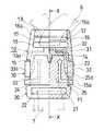
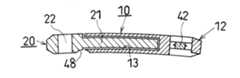
図1および2は、本発明に係るヘルメット用連結装置の第1の実施の形態を示したものである。両図において、10は、一端に差込口11を、他端側にテープ締部12をそれぞれ有する扁平箱形状の受具、20は、一端側に前記受具10に差込み可能な挿入部21を、他端側にテープ挿通孔22をそれぞれ有する差込具である。受具10は、後に詳述するようにそのテープ締具12を利用して前記ヘルメット5の耳掛テープ6(図11、12)に通し掛けされ、一方、差込具20にはそのテープ挿通孔22を利用して前記あごテープ7(図11、12)が連繋されるようになっている。
【0011】
上記受具10は、全体として扁平箱形状をなしており、前記差込口11から続くその内空部13は、テープ締部12に隣接する箇所に設けた仕切壁14で止まりとなっている。受具10はまた、その左右側壁の、前記差込口11に偏った部分に内空部14を外部に開放する長孔15を設けている。
【0012】
上記受具10の他端側に設けたテープ締部12は、ここでは、前記仕切壁14を共用する矩形の枠部16と、この枠部16を構成する左右の側板16a間に橋架された分割片(固定分割片)17と、この分割片17により分割された、枠部16内の2つのベルト挿通孔18、19とからなっている。枠部16を構成する先端側の端板16bは、受具10の裏面側(使用時に顔面に対面する側)に偏倚する箇所に該裏面と平行をなすように配置されている。また、前記分割片17は、アングル状をなし、受具10のおもて面側に偏倚する箇所に内側を下向きにして配置されている。このテープ締部12には、図2に示されるように2つのテープ挿通孔18、19を通して分割片17で折返す態様で前記耳掛テープ6が連繋されるようになており、この状態で耳掛テープ6に受具10の裏面に沿う方向の張力Fがかかると、テープ締部12から耳掛テープ6に締付力が作用する。
【0013】
一方、差込具20は、その挿入部21の両側に一対の爪片23を設けている。この一対の爪片23は、先端側を残すように挿入部21に設けたL字形スリット24により腕状に形成されており、その自由端部は、受具10に対する抜け方向へ向かうに従って次第に側方へ張り出す拡張部25となっている。ここで、左右一対の爪片23間におけるそれぞれの拡張部25の先端エッジを結ぶ間隔は、前記受具10の差込口11の幅寸法よりもわずか大きくなっており、これにより、いま、差込具20の挿入部21を受具10に差込むと、前記一対の爪片23が、相互に内側へ弾性変形して差込口11を通過した後、元の状態に復帰する。そして、一対の爪片23が元の状態に復帰すると、それぞれの拡張部25の先端エッジ部分が前記受具10の側面に設けた長孔15内にわずか入り込み、これにより該先端エッジ部分が長孔15の、差込口側内端15aに着座し、受具10に対する差込具20の抜けが規制(ロック)される。
【0014】
受具10の内空部13の底部側には、門形をなすアンロック用操作部材30が内装されている。この操作部材30は、その底片に設けたボス部31を受具10の仕切壁14に設けた貫通孔14aに嵌入させると共に、受具10を通して前記ボス部31に打込んだピン32により受具10に対して抜け止めされている。また、この操作部材30の左右の脚片には前記受具10の側面の長孔15に嵌入可能な把持部33が一体に形成されている。この把持部33は、常時は受具10の側面からわずか外側へ突出するようにその厚さが設定されており、その外表面には波形の滑止め部33aが設けられている。また、この把持部33の先端側の内縁は、常時は前記左右一対の爪片23の拡張部25の外側傾斜面25aに当接するようになっている。したがって、いま、差込具20が受具10に差込まれて抜け不能にロックされた状態(図1)のもと、この操作部材30の左右の把持部33を指で挟んで内側へ変形させると、各把持部33の内縁が前記傾斜面25a上を滑動しながら差込具20の左右の爪片23に内向きでかつ抜け方向の力を加え、これにより差込具20はワンタッチで受具10から抜ける(アンロックされる)ようになる。
【0015】
上記のように構成した連結装置において、その受具10は、図2に示したように裏面側からテープ締部12の2つのテープ挿通孔18、19を通して分割片17で折返す態様で耳掛テープ6の1つに通し掛けされる。また、差込具20は、そのテープ挿通孔22に他側の耳掛テープ6から延ばしたあごテープ7を通して折返し、さらにその折返し端部をアジャスタ(図示略)により締付け固定することで、該あごテープ7に連繋される。この場合、受具10に対して差込具20を差込む前段階では、耳掛テープ6が緩んだ(緊張していない)状態にあるので、着用者に合せて受具10を耳掛テープ6に沿って移動させ、耳掛テープ6に対する受具10の連繋部の片寄りをなくするように位置調整する。
【0016】
そして、この調整後、受具10に対して差込具20を差込むと、差込具20の挿入部21に設けた左右一対の爪片23の作用で、受具10と差込具20とは抜け不能にロックされ、この結果、あごテープ7の一端は本締付装置を介して片側の耳掛テープ6に連結される。この時、前記アジャスタによりあごテープ7の長さを調整することで、耳掛テープ6は緊張状態となる。すると、受具10に設けたテープ締部12から耳掛テープ6に締付力が作用し、受具10は耳掛テープ6に対して位置固定される。すなわち、片側の耳掛テープ6に対するあごテープ7の連繋部は不動の状態となり、したがって、使用中、前記図11に示したように前側または後側からヘルメット5に外力F1またはF2が加わっても、ヘルメット5は脱落することはない。
【0017】
ここで、図3に示すように、上記受具10のテープ締部12と同様の構造を有するテープ締部12´とテープ挿通孔35とを有するテープ締具36を用意して、このテープ締具36を、他側の耳掛テープ6に対するあごテープ7の連繋に用いるようにしてもよい。なお、図3には、上記テープ締部12に対応する構成要素にダッシュ(´)を付して示している。この場合は、該テープ締具36のテープ締部12´をあごテープ7に通し掛けし、かつそのテープ挿通孔35にあごテープ7の一端に設けた輪状部37を連繋する。このようなテープ締具36を用いることで、上記連結装置を設けた側と同様に他側の耳掛テープ6に対するあごテープ7の連繋部の片寄りを解消することができることはもちろん、耳掛テープ6が緊張した状態では該連繋部を位置固定することができ、ヘルメット5の脱落はより確実に防止される。なお、このテープ締具36は、そのテープ締部12´をテープ挿通孔35を設けた部分にも適用してもよいもので、この場合は、あごテープ7の一端に輪状部37を設ける必要はなくなる。
【0018】
図4および5は、本発明に係るヘルメット用連結装置の第2の実施の形態を示したものである。なお、本第2の実施の形態における受具10および差込具20の基本構造は、上記操作部材30(図1)を省略して、該操作部材30の操作部33に相当する操作部33´を受具10に一体に設けた点を除くと、第1の実施の形態と同じであるので、ここでは、同一部分に同一符号を付し、それらの説明を省略することとする。本第2の実施の形態の特徴とするところは、受具10の他端側に設けるテープ締部の構造を変更した点にある。
【0019】
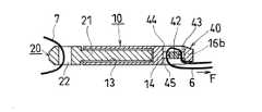
すなわち、本第2の実施の形態におけるテープ締部40は、前記受具10の仕切壁14を共用する矩形の枠部16と、この枠部16を構成する左右の側板16a間に平行移動可能に橋架された分割片(可動分割片)42と、この分割片42により分割された、枠部16内の2つのベルト挿通孔43、44とからなっている。枠部16を構成する先端側の端板16bは、ここでは受具10の厚さ方向に起立する状態で配置されている。前記可動分割片42は、板状をなし、前記左右の側板16aに形成した長孔45内に両端部を摺動可能に嵌合させている。また、この可動分割片42の両端部には、端面を波形に形成した把持部42aが一体に設けられており、この把持部42aは、枠部16の側板16aの側面からわずか突出するように位置決めされている。このテープ締部40には、図5に示されるように2つのテープ挿通孔43、44を通して分割片42で折返す態様で前記耳掛テープ6が連繋されるようになっており、この状態で耳掛テープ6に受具10の裏面に沿う方向の張力Fがかかると、前記可動分割片42が端板16b側へ移動し、テープ締部40から耳掛テープ6に締付力が作用すると同時に、可動分割片42と端板16bとの間に耳掛テープ6が挟持されるようになる。なお、可動分割片42には、多数の小突起46が設けられており、この小突起46が滑り止めとなって、耳掛テープ6に対してより確実に締付力が作用する。
本第2の実施の形態としての連結装置の使用態様並びに基本的な作用効果は、上記第1の実施の形態と同様であるが、耳掛テープ6が緩んでいる状態では、テープ締部40の可動分割片42の把持部42aを指で挟んで自由に移動させることができるので、ヘルメットを被った状態でも耳掛テープ6に対する受具10の連繋部の位置を調整することができ、より簡単にかつ正確に位置調整を行うことできる。また、耳掛テープ6の緊張に応じてテープ締部40の可動分割片42が端板16b側へ移動するので、可動分割片42と端板16bとの間に耳掛テープ6が強固に挟持され、この結果、ヘルメット5の脱落はより確実に防止されるようになる。さらに、可動分割片42の移動により締付力が発生するので、その両側のテープ挿通孔43、44を大きめに設定することができ、その分、種々の厚みの耳掛テープ6に汎用的に使用できる。
なお、この可動分割片42を備えたテープ締部40の構造は、上記第1の実施の形態におけるテープ締部12に代えてそのまま用いるようにしてもよいものである。
【0020】
図6および7は、本発明に係るヘルメット用連結装置の第3の実施の形態を示したものである。なお、本第3の実施の形態における受具10および差込具20の基本構造は、上記第2の実施の形態と同じであるので、ここでは、同一部分に同一符号を付し、それらの説明を省略することとする。本第3の実施の形態の特徴とするところは、差込具20の挿入部21の先端部21aを、受具10の仕切壁14を貫通させてテープ締部12のベルト挿通孔44内に突出させた点にある。
本第3の実施の形態としての連結装置の使用態様並びに基本的な作用効果は、上記第2の実施の形態と同様であるが、差込具20を受具10に差込むと、差込具20の挿入部21の先端部21aが耳掛テープ6を可動分割片42に対して押え、耳掛テープ6に対するあごテープ7の連繋部はより確実に位置固定される。この場合、前記可動分割片42は、第1の実施の形態における固定分割片17に代えてもよいことは、もちろんである。
【0021】
ここで、上記第1乃至第3の実施の形態における各連結装置は、その受具10および差込具20を含めた全体を、顔面に倣うように湾曲形状としてもよいものである。図8は、上記第2の実施の形態としての連結装置をこのように湾曲形状とした状態を示したもので、この場合は、その湾曲凹面が顔面に添うことで、使用感が向上する。また、上記各連結装置は、同じく図8に示すように、その受具10と差込具20との合せ部であって、顔面に当る側に凹部48を設けるようにしてもよく、この場合は、受具10と差込具20との合せ部が直接顔面に当ることがないので、誤って両者の間に肉が挟まれることはなくなり、安全性が向上する。
【0022】
図9および10は、本発明に係るヘルメット用連結装置の第4の実施の形態を示したものである。なお、本第4の実施の形態における受具10および差込具20の基本構造は、上記第1の実施の形態と同じであるので、ここでは、同一部分に同一符号を付し、それらの説明を省略することとする。本第4の実施の形態の特徴とするところは、受具10の他端側に設けるテープ締部の設置箇所を変更した点にある。
【0023】
すなわち、本第4の実施の形態におけるテープ締部50は、前記受具10の裏面側に該裏面と所定の間隙Sを開けて平行配置した支持板51上に配設されている。支持板51は、受具10と一体に成形され、その一端部が受具10の差込口11側に寄った部分に連接部52を介して支承されている。しかして、この支持板51には、所定の間隔を開けて2つのベルト挿通孔53、54が設けられており、この2つのベルト挿通孔53と54との間は分割片55として構成されている。2つのベルト挿通孔53、54のうち、支持板51の自由端側に位置するベルト挿通孔53は、受具10に対する差込具20の差込方向にわずか傾斜するように配置されている。このテープ締部50には、図10に示したように支持板51と受具10との間隙Sを利用して、その2つのテープ挿通孔53、54を通して分割片55で折返す態様で耳掛テープ6の1つが連繋され、この状態で耳掛テープ6に受具10の裏面に沿う方向の張力Fがかかると、テープ締部50から耳掛テープ6に締付力が作用するようになる。
本第4の実施の形態としての連結装置の使用態様並びに作用効果は、上記第1の実施の形態と同様であるが、テープ締具50が受具10に重なる状態で設置されているので、受具10の全長が短くなり、より耳掛テープ6に近い箇所であごテープ7を耳掛テープ6に連繋することができ、使用時に、連結装置があご側に寄ることがないので、使用感が向上する。
【0024】
なお、上記各実施の形態においては、差込具20のテープ挿通孔22に他側の耳掛テープ6から延ばしたあごテープ7を通して折返し、その折返し端部をアジャスタ(図示略)により締付け固定するようにしたが、本発明は、この差込具20にも、そのテープ挿通孔22に代えて、第1乃至第3の実施の形態におけるテープ締部12、40を設けるようにしてもよく、この場合は、前記した特別のアジャスタは不要になる。
また、上記第1乃至第3の実施の形態においては、受具10にテープ締部12、40を設けて、受具10を耳掛テープ6に通し掛けするようにしたが、本発明は、該テープ締部12、40を差込部20に設けて、差込部20を耳掛部テープ6に通し掛けするようにしてもよいものである。
【0025】
【発明の効果】
以上、説明したように、本発明に係るヘルメット用連結装置によれば、耳掛テープに対するあごテープの連繋部を位置調整できることはもちろん、耳掛テープの緊張時には該連繋部を位置固定できるので、ヘルメットの脱落防止に大きく寄与するものとなる。
【図面の簡単な説明】
【図1】本発明に係るヘルメット用連結装置の第1の実施の形態を一部断面として示す平面図である。
【図2】図1のX−X矢視線に沿う断面図である。
【図3】他側の耳掛テープに対するあごテープの連繋に用いるテープ締具の構造を示す平面図である。
【図4】本発明に係るヘルメット用連結装置の第2の実施の形態を一部断面として示す平面図である。
【図5】図4のX´−X´矢視線に沿う断面図である。
【図6】本発明に係るヘルメット用連結装置の第3の実施の形態を示す平面図である。
【図7】図6のX"−X"矢視線に沿う断面図である。
【図8】第2の実施の形態としての連結装置を全体に湾曲させた状態を示す断面図である。
【図9】本発明に係るヘルメット用連結装置の第4の実施の形態を示す平面図である。
【図10】図8に示した連結装置を一部断面として示す側面図である。
【図11】ヘルメットに対する従来の連結装置の使用態様を示す模式図である。
【図12】従来の連結装置の使用態様を拡大して示す斜視図である。
【図13】従来のヘルメット脱落防止対策の1つの実施形態を示す斜視図である。
【図14】従来のヘルメット脱落防止対策の他の実施形態を示す斜視図である。
【図15】図13に示したヘルメット脱落防止対策における不具合発生状態を示す模式図である。
【符号の説明】
5 ヘルメット、 6 耳掛テープ、 7 あごテープ
10 受具
12、40、50 テープ締部
16 枠部
17、42、55 分割片
18,19、43,44、53,54 ベルト挿通孔
20 差込具
21 差込具の挿入部
30 操作部材、 33 操作部[0001]
BACKGROUND OF THE INVENTION
The present invention relates to a one-touch type coupling device for coupling a jaw tape to an ear hook tape provided on both sides of a helmet.
[0002]
[Prior art]
Conventionally, as shown in FIG. 11 and FIG. 12, this type of helmet connecting device is a flat having an insertion port (not shown) at one end and a
[0003]
In order to use such a connecting
[0004]
[Problems to be solved by the invention]
However, according to the connection mode of the
[0005]
As a countermeasure against this, for example, as shown in FIG. 13, a
[0006]
The present invention has been made in view of the above-described conventional problems, and the problem is that the position of the link portion of the jaw tape with respect to the ear hook tape can be adjusted, as well as the connection portion during tension of the ear hook tape. It is an object of the present invention to provide a highly safe connecting device for a helmet that can fix the position of the helmet and greatly contribute to preventing the helmet from falling off.
[0007]
[Means for Solving the Problems]
In order to solve the above-mentioned problem, the present invention is a connecting device for connecting a chin tape to an ear hook tape provided on both sides of a helmet, and a receiving tool having an insertion port at one end, and can be inserted into the receiving tool. and a plug member having a insertion portion at one end, the helmet coupling device to which both are unlocked by both locked and external operation in accordance with the insertion of the plug member relative to the female component, thereceiving The tool is provided with a tape fastening portion having two tape insertion holes divided by a rod-like divided piece, and the divided piece is bridged in a rectangular frame so as to be movable in parallel, and theend pieceis corrugated . Both ends are projected to the outside of the frame so as to be externally operable, and areceiving tool having the tape fastening portion is passed through one of the ear hook tapes in such a manner that it is folded back by the divided piece through the two tape insertion holes. and, tothe insertion tool , Tandem the jaw tape extended from the other side of the ear tape, the divided piece is moved in accordance with the tension of the ear tape,while pressing the the ear hanging tape to theframe, the difference with respect to the receiving fixture In accordance with the insertion of the insertion tool, the tip of the insertion part of the insertion tool presses thehook tape against the divided piece of the tape fastening part .
In the helmet connecting apparatus configured as described above, since the tape fastening portion can be freely moved with respect to the ear hook tape in a state where the ear hook tape is not tensed, the jaw tape is linked to the ear hook tape. The offset of the part can be eliminated. Further, in a state where the hook tape is in tension, the tape tightening portion acts so as to tighten the hook tape, so that the connecting portion does not move. Further, since the divided piece moves according to the tension of the ear hook tape and presses the ear hook tape against the frame, the position of the connecting portion of the jaw tape to the ear hook tape is more reliably fixed.At the same time that the insertion tool is inserted into the receiver, the tip of the insertion portion of the insertion tool presses the ear hook tape, so that the position of the link portion of the jaw tape with respect to the ear hook tape is more reliably fixed.
[0009]
DETAILED DESCRIPTION OF THE INVENTION
Hereinafter, embodiments of the present invention will be described with reference to the drawings.
[0010]
1 and 2 show a first embodiment of a helmet coupling device according to the present invention. In both figures, 10 is a flat box-shaped receptacle having an
[0011]
The
[0012]
Here, the
[0013]
On the other hand, the
[0014]
On the bottom side of the
[0015]
In the connecting device configured as described above, the receiving
[0016]
Then, after this adjustment, when the
[0017]
Here, as shown in FIG. 3, a
[0018]
4 and 5 show a second embodiment of the helmet coupling device according to the present invention. Note that the basic structure of the
[0019]
That is, the
The usage and basic operational effects of the coupling device as the second embodiment are the same as those of the first embodiment. However, when the
Note that the structure of the
[0020]
6 and 7 show a third embodiment of a helmet coupling device according to the present invention. In addition, since the basic structure of the receiving
The use mode and the basic operation and effect of the coupling device as the third embodiment are the same as those of the second embodiment. However, when the
[0021]
Here, each of the coupling devices in the first to third embodiments may have a curved shape so that the entirety including the receiving
[0022]
9 and 10 show a fourth embodiment of a helmet coupling device according to the present invention. In addition, since the basic structure of the receiving
[0023]
That is, the
The usage mode and operational effects of the coupling device as the fourth embodiment are the same as those of the first embodiment, but the
[0024]
In each of the above embodiments, the
Moreover, in the said 1st thru | or 3rd embodiment, although the tape clamp | tightening
[0025]
【The invention's effect】
As described above, according to the helmet coupling device according to the present invention, not only can the position of the link portion of the chin tape to the ear hook tape be adjusted, but also the position of the link portion can be fixed when the ear hook tape is in tension. This will greatly contribute to preventing the helmet from falling off.
[Brief description of the drawings]
FIG. 1 is a plan view showing a first embodiment of a helmet coupling device according to the present invention as a partial cross section.
FIG. 2 is a cross-sectional view taken along the line XX in FIG.
FIG. 3 is a plan view showing a structure of a tape fastener used for connecting a jaw tape to an ear hook tape on the other side.
FIG. 4 is a plan view showing a second embodiment of the helmet coupling device according to the present invention as a partial cross section.
5 is a cross-sectional view taken along the line X′-X ′ in FIG.
FIG. 6 is a plan view showing a third embodiment of a helmet coupling device according to the present invention.
7 is a cross-sectional view taken along the line X ″ -X ″ in FIG. 6.
FIG. 8 is a cross-sectional view showing a state in which the coupling device according to the second embodiment is curved as a whole.
FIG. 9 is a plan view showing a fourth embodiment of a helmet coupling device according to the present invention.
10 is a side view showing the coupling device shown in FIG. 8 as a partial cross-section. FIG.
FIG. 11 is a schematic view showing how the conventional connecting device is used for a helmet.
FIG. 12 is an enlarged perspective view showing a usage state of a conventional coupling device.
FIG. 13 is a perspective view showing one embodiment of a conventional helmet drop-off prevention measure.
FIG. 14 is a perspective view showing another embodiment of a conventional helmet drop-off prevention measure.
FIG. 15 is a schematic diagram showing a failure occurrence state in the helmet dropout prevention measure shown in FIG. 13;
[Explanation of symbols]
5 Helmet, 6 Ear hook tape, 7
Claims (1)
Translated fromJapanesePriority Applications (1)
| Application Number | Priority Date | Filing Date | Title |
|---|---|---|---|
| JP2001329161AJP3861215B2 (en) | 2001-10-26 | 2001-10-26 | Helmet connection device |
Applications Claiming Priority (1)
| Application Number | Priority Date | Filing Date | Title |
|---|---|---|---|
| JP2001329161AJP3861215B2 (en) | 2001-10-26 | 2001-10-26 | Helmet connection device |
Publications (2)
| Publication Number | Publication Date |
|---|---|
| JP2003129325A JP2003129325A (en) | 2003-05-08 |
| JP3861215B2true JP3861215B2 (en) | 2006-12-20 |
Family
ID=19145103
Family Applications (1)
| Application Number | Title | Priority Date | Filing Date |
|---|---|---|---|
| JP2001329161AExpired - LifetimeJP3861215B2 (en) | 2001-10-26 | 2001-10-26 | Helmet connection device |
Country Status (1)
| Country | Link |
|---|---|
| JP (1) | JP3861215B2 (en) |
Families Citing this family (2)
| Publication number | Priority date | Publication date | Assignee | Title |
|---|---|---|---|---|
| US7753050B2 (en) | 2001-09-07 | 2010-07-13 | Resmed Limited | Headgear connection assembly for a respiratory mask assembly |
| US7841345B2 (en) | 2004-01-16 | 2010-11-30 | Resmed Limited | Headgear connection assembly for a respiratory mask assembly |
- 2001
- 2001-10-26JPJP2001329161Apatent/JP3861215B2/ennot_activeExpired - Lifetime
Also Published As
| Publication number | Publication date |
|---|---|
| JP2003129325A (en) | 2003-05-08 |
Similar Documents
| Publication | Publication Date | Title |
|---|---|---|
| US7234209B2 (en) | Mounting structure and mounting method for vehicle interior parts | |
| TWI527720B (en) | Seat belt locking device | |
| TWI243031B (en) | Buckle | |
| JPS6257507A (en) | Buckle for leather string | |
| JPH07249453A (en) | Connector unlock structure | |
| JPH0870912A (en) | Buckle device for infant restraining/protecting sheet | |
| TWI730324B (en) | Bolt for buckle and buckle | |
| TWI462706B (en) | Cord lock | |
| JP3861215B2 (en) | Helmet connection device | |
| JP2001090886A (en) | Hose clamp | |
| JPH07304416A (en) | Tongue assembly for seat belt device | |
| JP5628585B2 (en) | buckle | |
| JP3430323B2 (en) | Slider for synthetic resin bag chuck | |
| JP2002262921A (en) | Fitting device for fitting portable article | |
| JP2001287620A (en) | Cover member for buckle | |
| JP4470076B2 (en) | Retention clip for protective equipment of ribbed helmet | |
| JPH0735130Y2 (en) | Metal clip | |
| JP4001525B2 (en) | Clip and clip fixing structure | |
| CA2920593C (en) | Spring actuated engagement device | |
| JPH0864977A (en) | Din rail fixture with lock | |
| JP3286489B2 (en) | Tongue plate for continuous 3-point seat belt | |
| JP2003269424A (en) | Fastening structure | |
| JP3231858B2 (en) | Self-lock release device | |
| JPH0756471Y2 (en) | Furniture hinges | |
| JP3462606B2 (en) | Buckle for safety belt for working at height |
Legal Events
| Date | Code | Title | Description |
|---|---|---|---|
| A977 | Report on retrieval | Free format text:JAPANESE INTERMEDIATE CODE: A971007 Effective date:20040122 | |
| A131 | Notification of reasons for refusal | Free format text:JAPANESE INTERMEDIATE CODE: A131 Effective date:20040421 | |
| A521 | Written amendment | Free format text:JAPANESE INTERMEDIATE CODE: A523 Effective date:20040602 | |
| A02 | Decision of refusal | Free format text:JAPANESE INTERMEDIATE CODE: A02 Effective date:20040811 | |
| A521 | Written amendment | Free format text:JAPANESE INTERMEDIATE CODE: A523 Effective date:20040902 | |
| A911 | Transfer to examiner for re-examination before appeal (zenchi) | Free format text:JAPANESE INTERMEDIATE CODE: A911 Effective date:20040913 | |
| A912 | Re-examination (zenchi) completed and case transferred to appeal board | Free format text:JAPANESE INTERMEDIATE CODE: A912 Effective date:20041008 | |
| A521 | Written amendment | Free format text:JAPANESE INTERMEDIATE CODE: A523 Effective date:20060809 | |
| A61 | First payment of annual fees (during grant procedure) | Free format text:JAPANESE INTERMEDIATE CODE: A61 Effective date:20060912 | |
| R150 | Certificate of patent or registration of utility model | Ref document number:3861215 Country of ref document:JP Free format text:JAPANESE INTERMEDIATE CODE: R150 Free format text:JAPANESE INTERMEDIATE CODE: R150 | |
| FPAY | Renewal fee payment (event date is renewal date of database) | Free format text:PAYMENT UNTIL: 20091006 Year of fee payment:3 | |
| FPAY | Renewal fee payment (event date is renewal date of database) | Free format text:PAYMENT UNTIL: 20101006 Year of fee payment:4 | |
| R250 | Receipt of annual fees | Free format text:JAPANESE INTERMEDIATE CODE: R250 | |
| FPAY | Renewal fee payment (event date is renewal date of database) | Free format text:PAYMENT UNTIL: 20111006 Year of fee payment:5 | |
| R250 | Receipt of annual fees | Free format text:JAPANESE INTERMEDIATE CODE: R250 | |
| FPAY | Renewal fee payment (event date is renewal date of database) | Free format text:PAYMENT UNTIL: 20111006 Year of fee payment:5 | |
| FPAY | Renewal fee payment (event date is renewal date of database) | Free format text:PAYMENT UNTIL: 20121006 Year of fee payment:6 | |
| R250 | Receipt of annual fees | Free format text:JAPANESE INTERMEDIATE CODE: R250 | |
| FPAY | Renewal fee payment (event date is renewal date of database) | Free format text:PAYMENT UNTIL: 20131006 Year of fee payment:7 | |
| R250 | Receipt of annual fees | Free format text:JAPANESE INTERMEDIATE CODE: R250 | |
| R250 | Receipt of annual fees | Free format text:JAPANESE INTERMEDIATE CODE: R250 | |
| R250 | Receipt of annual fees | Free format text:JAPANESE INTERMEDIATE CODE: R250 | |
| R250 | Receipt of annual fees | Free format text:JAPANESE INTERMEDIATE CODE: R250 | |
| R250 | Receipt of annual fees | Free format text:JAPANESE INTERMEDIATE CODE: R250 | |
| R250 | Receipt of annual fees | Free format text:JAPANESE INTERMEDIATE CODE: R250 | |
| S111 | Request for change of ownership or part of ownership | Free format text:JAPANESE INTERMEDIATE CODE: R313113 | |
| R350 | Written notification of registration of transfer | Free format text:JAPANESE INTERMEDIATE CODE: R350 | |
| R250 | Receipt of annual fees | Free format text:JAPANESE INTERMEDIATE CODE: R250 | |
| R250 | Receipt of annual fees | Free format text:JAPANESE INTERMEDIATE CODE: R250 | |
| R250 | Receipt of annual fees | Free format text:JAPANESE INTERMEDIATE CODE: R250 | |
| R250 | Receipt of annual fees | Free format text:JAPANESE INTERMEDIATE CODE: R250 | |
| EXPY | Cancellation because of completion of term |