JP3860474B2 - In-vehicle / portable map display device - Google Patents
In-vehicle / portable map display deviceDownload PDFInfo
- Publication number
- JP3860474B2 JP3860474B2JP2002002830AJP2002002830AJP3860474B2JP 3860474 B2JP3860474 B2JP 3860474B2JP 2002002830 AJP2002002830 AJP 2002002830AJP 2002002830 AJP2002002830 AJP 2002002830AJP 3860474 B2JP3860474 B2JP 3860474B2
- Authority
- JP
- Japan
- Prior art keywords
- vehicle
- map
- current position
- mode
- portable
- Prior art date
- Legal status (The legal status is an assumption and is not a legal conclusion. Google has not performed a legal analysis and makes no representation as to the accuracy of the status listed.)
- Expired - Lifetime
Links
- 238000001514detection methodMethods0.000claimsdescription11
- 238000012937correctionMethods0.000claimsdescription2
- 238000010586diagramMethods0.000description11
- 238000000034methodMethods0.000description11
- 238000012545processingMethods0.000description5
- 238000006243chemical reactionMethods0.000description4
- 239000004973liquid crystal related substanceSubstances0.000description2
- 238000012986modificationMethods0.000description2
- 230000004048modificationEffects0.000description2
- 238000013459approachMethods0.000description1
- 230000001413cellular effectEffects0.000description1
- 230000000694effectsEffects0.000description1
- 239000011159matrix materialSubstances0.000description1
Images


Landscapes
- Navigation (AREA)
- Traffic Control Systems (AREA)
- Instructional Devices (AREA)
Description
Translated fromJapanese【0001】
【発明の属する技術分野】
本発明は車載/携帯兼用地図表示装置に係り、とくに道路データを用いて現在位置を道路上に修正可能な車載/携帯兼用地図表示装置に関する。
【0002】
【従来の技術】
車載用ナビゲーション装置では、衛星航法または自立航法で現在位置を検出し、地図描画用の地図データを用いて現在位置周辺の地図画像を現在位置マークとともに描画し、液晶ディスプレイに表示するようにしている。
ところで、衛星航法または自立航法で検出した現在位置に誤差が有ると、現在位置マークは地図画像上の道路から外れた位置に表示されて不自然な表示状態となる。そこで、従来から車載用ナビゲーション装置では、衛星航法または自立航法で検出した現在位置を、道路データを用いて投影法、パターンマッチング法等のマップマッチングにより、現在位置データを道路上に修正したのち、図8に示す如く地図画像MIを現在位置マークVMとともに描画し、画面表示するようにしている。現在位置マークVMは地図画像MIの或る道路RDの上に乗っている。
【0003】
【発明が解決しようとする課題】
けれども、従来の車載用ナビゲーション装置を携帯用と兼用して用いようとする場合、図9に示す如く車両専用道路RDaの近くの車両と歩行者両用の一般道路RDbを歩行しているとき、衛星航法で検出した現在位置Pが誤差で車両専用道路RDaの方に近かったりすると、マップマッチングにより車両専用道路RDaの上に現在位置が間違って修正されてしまうことがあった(図9の符号P´)。本発明は上記した従来技術の問題に鑑み、車載用と携帯用のいずれで使用する場合もマップマッチングを正しく行える車載/携帯兼用地図表示装置を提供することを、その目的とする。
【0004】
【課題を解決するための手段】
本発明の請求項1記載の車載/携帯兼用地図表示装置では、現在位置を検出する現在位置検出手段と、地図描画用の地図データとマップマッチング用の道路データを記憶した記憶手段と、道路データを用いてマップマッチングにより、現在位置検出手段で検出された現在位置を修正する修正手段と、地図画像を現在位置マークとともに表示する表示手段と、地図データを用いて現在位置を含む一定範囲の地図画像を現在位置マークとともに描画し、表示手段に表示させる地図表示制御手段と、を備えた車載/携帯兼用地図表示装置において、使用モードを車載モードと携帯モードに切り替える使用モード切り替え手段を備えるとともに、記憶手段に記憶する道路データには車両用と歩行者用の2種類用意しておき、修正手段は、使用モードが車載モードの場合、車両用の道路データを用いてマップマッチングを行い、使用モードが携帯モードの場合、歩行者用の道路データを用いてマップマッチングを行うようにしたこと、を特徴としている。
請求項2では、使用モード切り替え手段は、ユーザによる使用モード切り替え操作に従い使用モードの切り替えを行うようにしたこと、を特徴としている。
請求項3では、使用モード切り替え手段は、車両に固定された架台への装置の着脱を検知して、架台に装着されたときは車載モード、架台から外されたときは携帯モードに使用モードを切り替えるようにしたこと、を特徴としている。
【0005】
【発明の実施の形態】
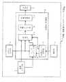
次に、本発明の一つの実施の形態を図1を参照して説明する。図1は本発明に係る車載/携帯兼用ナビゲーション装置の構成図である。
1は車載/携帯兼用地図表示装置の一例としての車載/携帯兼用ナビゲーション装置であり、所定の縮尺の地図描画用の地図データとマップマッチング用の道路データを記憶した地図メモリ部から、衛星航法で検出した現在位置周辺の地図画像の表示に必要な地図データを読み出し、該読み出した地図データを用いて、現在位置を中心に含む一定範囲の地図画像を現在位置マークとともに描画し、画面表示する。この際、車載で使用する際は衛星航法で検出した現在位置を、車両用道路データを用いてマップマッチングにより道路上に修正した現在位置データに基づき地図画像を現在位置マークとともに描画して画面表示させ、携帯で使用する際は衛星航法で検出した現在位置データを歩行者用道路データを用いてマップマッチングにより道路上に修正した現在位置データに基づき地図画像を現在位置マークとともに描画して画面表示させることができる。
【0006】
車載/携帯兼用ナビゲーション装置1の内、2は衛星航法により定期的に現在位置と現在方位を検出するGPS受信部、3は液晶ドットマトリクス式の表示部、4はエリア別の地図描画用の地図データと、エリア別のマップマッチングを行うための車両用道路データ及び歩行者用道路データが記憶された地図メモリ部である。ここで車両用道路データとは、車両が走行可能な道路の道路データであり、歩行者用道路データとは、歩行可能な道路の道路データである。5は操作部であり、装置の使用モードを車載モードと携帯モードに切り替える操作などをする。6はマイコン構成の地図表示制御部であり、この内、7は操作部5での使用モード切り替え操作に従い、各部の使用モードの切り替え処理を行う使用モード切り替え部、8はGPS受信部2で検出された現在位置を地図メモリ部4に記憶された道路データを用いてマップマッチングにより道路上に修正するマップマッチング部であり、使用モードが車載モードの場合、GPS受信部2で検出した現在位置を車両用道路データを用いてマップマッチングにより道路上に修正し、反対に使用モードが携帯モードの場合、GPS受信部2で検出した現在位置を歩行者用道路データを用いてマップマッチングにより道路上に修正する。9は表示部3の1画面分の画像記憶領域を有し、地図画像を記憶する画像メモリ部、10は描画部であり、地図メモリ部4に記憶された地図データを用いて現在位置を中心とする1画面分で北を上向きとした地図画像を画像メモリ部9に描画するとともに、当該描画した地図画像の中心に現在方位に相当する向きで現在位置マークを描画する。11は画像メモリ部9に記憶された画像を読み出し所定の映像信号に変換しながら表示部3へ出力し、現在位置マーク付の地図画像を画面表示させる映像変換部である。
【0007】
車載/携帯兼用ナビゲーション装置1は片手で持てる大きさで方形の箱形に形成されており、図2に示す如く、車両の車室内前部のダッシュボード20に固定された架台(クレイドル)21に着脱自在に装着できるようになっている。
【0008】
図3は地図表示制御部6による地図表示制御処理を示すフローチャート、図4は携帯モードでのマップマッチングの説明図、図5は表示部3での表示例を示す説明図であり、以下、これらの図を参照して上記した実施の形態の動作を説明する。なお、予め、使用モード切り替え部7の図示しない内蔵メモリに記憶された現在モードフラグF(0;車載モード、1;携帯モード)が車載モードを示す0になっているものとする。また、車載/携帯兼用ナビゲーション装置1は図示しない内蔵バッテリ部より各部に所定の直流電源が供給されるものとする。
【0009】
(1)車載モード
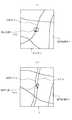
ユーザが車載/携帯兼用ナビゲーション装置1を車載モードで使用したい場合、図2に示す如く、車両の車室内のダッシュボード20に固定された架台21に車載/携帯兼用ナビゲーション装置1を装着しておく。車載/携帯兼用ナビゲーション装置1の電源キー(図示せず)を押して電源をオンすると、GPS受信部2が衛星航法により定期的に現在位置と現在方位を検出して出力する。一方、地図表示制御部6は電源オンに伴い、まず使用モード切り替え部7がFをチェックし、ここでは0なのでマップマッチング部8と描画部10を車載モードに切り替える(図3のステップS10、S11)。続いて、地図表示制御部6はGPS受信部2から現在位置と現在方位を入力し、マップマッチング部8が地図メモリ部4に記憶された現在位置周辺の車両用道路データを用いてマップマッチングによりGPS受信部2から入力した現在位置を車両が走行可能な道路上に修正する(ステップS12、S13)。そして、描画部10がマップマッチング部8で修正後の現在位置データに基づき、地図メモリ部4に記憶された現在位置周辺の地図データを用いて修正後の現在位置を中心とする北を上向きとした地図画像を画像メモリ部9に描画し、かつ、当該地図画像の中心にGPS受信部2から入力した現在方位に相当する向きで車載モード用の現在位置マークを重ねて描画する(ステップS14)。画像メモリ部9に描画された画像は映像変換部11により所定の映像信号に変換されて表示部3へ出力され、画面表示される(ステップS15)。画面には図5(1)に示す如く、地図画像MIの中心に車両が走行可能な道路RDcに乗った車載モード用の現在位置マークVMが表示されるので、現在位置がどこであるか地図上で確認できる。
【0010】
ステップS15のあと、使用モード切り替え部7が操作部5で使用モード切り替え操作がされたかチェックし(ステップS16)、ここではNOなので地図表示制御部6はFが0であることを確認したのち(ステップS17)、ステップS12に戻って前述と同様の処理を繰り返す。この結果、車両の移動に伴い、地図画像MIの上で現在位置マークVMが相対移動する。
【0011】
(2)携帯モード
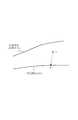
その後、ユーザが車載/携帯兼用ナビゲーション装置1を車外へ持ち出して携帯モードで使用したい場合、架台21から車載/携帯兼用ナビゲーション装置1を取り外すとともに、操作部5で使用モード切り替え操作を行う。すると、使用モード切り替え部7がステップS16でYESと判断し、Fを反転して1とする(ステップS18)。そして、マップマッチング部8と描画部10を携帯モードに切り替える(図3のステップS10、S19)。続いて、地図表示制御部6はGPS受信部2から現在位置と現在方位を入力し、マップマッチング部8が地図メモリ部4に記憶された現在位置周辺の歩行者用道路データを用いてマップマッチングによりGPS受信部2から入力した現在位置を歩行者が歩行可能な道路上に修正する(ステップS20、S21)。このとき、ユーザが図4に示す如く車両専用道路RDaの近くの車両と歩行者両用の一般道路RDbを歩行しているとき、衛星航法で検出した現在位置Pが誤差で車両専用道路RDaの方により近かった場合でも、歩行者用道路データには車両専用道路RDaのデータが存在しないので、一般道路RDbの上に現在位置が正しく修正される(図4の符号P´)。
【0012】
このあと、描画部10がマップマッチング部8で修正後の現在位置データに基づき、地図メモリ部4に記憶された現在位置周辺の地図データを用いて修正後の現在位置を中心とする北を上向きとした地図画像を画像メモリ部9に描画し、かつ、当該地図画像の中心にGPS受信部2から入力した現在方位に相当する向きで携帯モード用の現在位置マークを重ねて描画する(ステップS22)。画像メモリ部9に描画された画像は映像変換部11により所定の映像信号に変換されて表示部3へ出力され、画面表示される(ステップS15)。画面には図5(2)に示す如く、地図画像MIの中心に現在位置マークMMが表示されるが、該現在位置マークMMは車両専用道路RDaでなく一般道路RDbに乗っているので、現在位置がどこであるか地図上で正しく確認できる。また、現在位置マークMMの形から携帯モードに切り替わっていることが容易に判る。
【0013】
ステップS15のあと、使用モード切り替え部7が操作部5で使用モード切り替え操作がされたかチェックし(ステップS16)、ここではNOなので地図表示制御部6はFが1であることを確認したのち(ステップS17)、ステップS20に戻って前述と同様の処理を繰り返す。この結果、ユーザの歩行に伴い、地図画像MIの上で現在位置マークMMが相対移動する。
【0014】
この実施の形態によれば、ユーザが車載モードに切り替えた場合、車両用道路データを用いてマップマッチングにより現在位置が修正されるので、地図画像上の現在位置マークは車両で走行可能な道路上に正しく乗り、反対に、ユーザが携帯モードに切り替えた場合、歩行者用道路データを用いてマップマッチングにより現在位置が修正されるので、地図画像上の現在位置マークは歩行者が歩行可能な道路上に正しく乗る。また、現在位置マークの形から使用モードが車載モードと携帯モードのいずれに切り替わっているか容易に判る。
【0015】
なお、上記した実施の形態では使用モードはユーザが操作部5で切り替え操作をすることで切り替わるようにしたが、本発明は何らこれに限定されず、架台21への着脱に連動して自動的に切り替わるようにしても良い。
例えば、図6に示す如く、架台21Aの底部22に突起23を設けておくとともに、車載/携帯兼用ナビゲーション装置1Aの側には、該車載/携帯兼用ナビゲーション装置1Aを架台21Aに装着したとき突起23にアクチュエータ(図示せず)が押されて接点を閉じるスイッチ部(マイクロスイッチ等)12を設けておく。スイッチ部12は接点が閉じているときLレベル、開いているときHレベルとなるスイッチ信号を出力するようにする。そして、使用モード切り替え部7Aは図3のステップS10でFの値をチェックする代わりに、スイッチ部12から出力されたスイッチ信号のレベルをチェックし、車載/携帯兼用ナビゲーション装置1Aが架台21Aに装着されていてスイッチ信号がLレベルのときはステップS11に進み、反対に車載/携帯兼用ナビゲーション装置1Aが架台21Aから取り外されていてHレベルのときはステップS19に進むようにする。同様に、図3のステップS17でFの値をチェックする代わりに、スイッチ信号のレベルをチェックし、車載/携帯兼用ナビゲーション装置1Aが架台21Aに装着されていてスイッチ信号がLレベルのときはステップS12に進み、反対に車載/携帯兼用ナビゲーション装置1Aが架台21Aから取り外されていてHレベルのときはステップS20に進むようにしても良い。図6の例によれば、ユーザがとくに使用モード切り替え操作をしなくても、車載で使用するため車載/携帯兼用ナビゲーション装置1Aを架台21Aに装着すれば、装着されたことが検知されて自動的に車載モードとなり、携帯で使用するため車載/携帯兼用ナビゲーション装置1Aを架台21Aから取り外せば、取り外したことが検知されて自動的に携帯モードとなり、手間が省ける。
【0016】
また、例えば、図7に示す如く、架台21Bの底部22にカーバッテリからの電源(+B)を外部に給電可能なオス形電源端子24、25を設けておくとともに、車載/携帯兼用ナビゲーション装置1Bの側には、該車載/携帯兼用ナビゲーション装置1Bを架台21Bに装着したときオス形電源端子24、25と各々着脱自在に嵌合するメス形電源端子13、14を設けておく。更に、車載/携帯兼用ナビゲーション装置1Bには所定の直流電圧+Vを各部に供給する内蔵バッテリ部(2次電池タイプ)15のほか、カーバッテリからの外部電源(+B)から所定の直流電圧+Vを形成して各部に供給するDC/DCコンバータ部16と、メス形電源端子13、14への+Bの給電を検知し、給電されているときLレベル、されていないときHレベルの外部電源検知信号を出力する外部電源検知部17とを設けておく。そして、使用モード切り替え部7Bは図3のステップS10でFの値をチェックする代わりに、外部電源検知部17から出力された外部電源検知信号のレベルをチェックし、車載/携帯兼用ナビゲーション装置1Bが架台21Bに装着されていて外部電源検知信号がLレベルのときはステップS11に進み、反対に車載/携帯兼用ナビゲーション装置1Bが架台21Bから取り外されていてHレベルのときはステップS19に進むようにする。同様に、図3のステップS17でFの値をチェックする代わりに、外部電源検知信号のレベルをチェックし、車載/携帯兼用ナビゲーション装置1Bが架台21Bに装着されていて外部電源検知信号がLレベルのときはステップS12に進み、反対に車載/携帯兼用ナビゲーション装置1Bが架台21Bから取り外されていてHレベルのときはステップS20に進むようにしても良い。図7の例によっても、ユーザがとくに使用モード切り替え操作をしなくても、車載で使用するため車載/携帯兼用ナビゲーション装置1Bを架台21Bに装着すれば該装着が検知されて自動的に車載モードとなり、携帯で使用するため車載/携帯兼用ナビゲーション装置1Bを架台21Bから取り外せば、該取り外しが検知されて自動的に携帯モードとなり、手間が省ける。
【0017】
【発明の効果】
本発明によれば、使用モードが車載モードに切り替わると、車両用道路データを用いてマップマッチングにより現在位置が修正されるので、地図画像上の現在位置マークは車両で走行可能な道路上に正しく乗り、反対に、携帯モードに切り替わると、歩行者用道路データを用いてマップマッチングにより現在位置が修正されるので、地図画像上の現在位置マークは歩行者が歩行可能な道路上に正しく乗る。
【図面の簡単な説明】
【図1】本発明の一つの実施の形態に係る車載/携帯兼用ナビゲーション装置の構成図である。
【図2】図1の車載/携帯兼用ナビゲーション装置の車両への設置方法の説明図である。
【図3】図1中の地図表示制御部による地図表示制御処理を示すフローチャートである。
【図4】図1中のマップマッチング部による携帯モード下でマップマッチング処理の説明図である。
【図5】図1中の表示部での画面表示例を示す説明図である。
【図6】図1の車載/携帯兼用ナビゲーション装置の変形例を示す構成図である。
【図7】図1の車載/携帯兼用ナビゲーション装置の他の変形例を示す構成図である。
【図8】従来の車載用ナビゲーション装置での画面表示例を示す説明図である。
【図9】従来のマップマッチングの問題点の説明図である。
【符号の説明】
1、1A、1B 車載/携帯兼用ナビゲーション装置
2 GPS受信部 3 表示部
4 地図メモリ部 5 操作部
6 地図表示制御部
7、7A、7B 使用モード切り替え部
8 マップマッチング部 9 画像メモリ部
10 描画部 11 映像変換部
12 スイッチ部 13、14 メス形電源端子
15 内蔵バッテリ部 16 DC/DCコンバータ部
17 外部電源検知部 21、21A、21B 架台
23 突起 24、25 オス形電源端子[0001]
BACKGROUND OF THE INVENTION
The present invention relates to an on-vehicle / portable map display device, and more particularly to an on-vehicle / portable map display device that can correct a current position on a road using road data.
[0002]
[Prior art]
The in-vehicle navigation system detects the current position by satellite navigation or self-contained navigation, draws a map image around the current position using map data for map drawing, and displays it on the liquid crystal display. .
By the way, if there is an error in the current position detected by satellite navigation or self-contained navigation, the current position mark is displayed at a position off the road on the map image, resulting in an unnatural display state. Therefore, in the conventional vehicle-mounted navigation device, after correcting the current position data on the road by map matching such as projection method and pattern matching method using the road data, the current position detected by satellite navigation or self-contained navigation, As shown in FIG. 8, the map image MI is drawn together with the current position mark VM and displayed on the screen. The current position mark VM is on a certain road RD of the map image MI.
[0003]
[Problems to be solved by the invention]
However, when the conventional in-vehicle navigation device is used for both portable use and when walking on a general road RDb for both vehicles and pedestrians as shown in FIG. If the current position P detected by navigation approaches the vehicle-only road RDa due to an error, the current position may be erroneously corrected on the vehicle-only road RDa by map matching (reference P inFIG. 9 ). ´). The present invention has been made in view of the above-described problems of the prior art, and an object thereof is to provide an on-vehicle / portable map display device that can correctly perform map matching when used in both on-vehicle and portable.
[0004]
[Means for Solving the Problems]
In the on-vehicle / portable map display device according to
According to a second aspect of the present invention, the usage mode switching means switches the usage mode in accordance with a usage mode switching operation by the user.
According to a third aspect of the present invention, the use mode switching means detects attachment / detachment of the device to / from the gantry fixed to the vehicle, and sets the use mode to the in-vehicle mode when the device is attached to the gantry and to the portable mode when the device is removed from the gantry. It is characterized by the fact that it has been switched.
[0005]
DETAILED DESCRIPTION OF THE INVENTION
Next, one embodiment of the present invention will be described with reference to FIG. FIG. 1 is a configuration diagram of a vehicle-mounted / portable navigation device according to the present invention.
[0006]
Of the in-car /
[0007]
The vehicle-mounted /
[0008]
FIG. 3 is a flowchart showing map display control processing by the map
[0009]
(1) On-vehicle mode When the user wants to use the on-vehicle /
[0010]
After step S15, the use
[0011]
(2) Mobile mode After that, when the user wants to take the in-vehicle /
[0012]
Thereafter, the drawing unit 10 uses the map data around the current position stored in the
[0013]
After step S15, the use
[0014]
According to this embodiment, when the user switches to the in-vehicle mode, the current position is corrected by map matching using the vehicle road data. When the user switches to the mobile mode correctly, the current position is corrected by map matching using the pedestrian road data, so the current position mark on the map image is a road onwhich the pedestrian can walk Get on top correctly. Further, it can be easily understood from the shape of the current position mark whether the use mode is switched to the in-vehicle mode or the portable mode.
[0015]
In the above-described embodiment, the use mode is switched by the user performing a switching operation with the operation unit 5. However, the present invention is not limited to this, and the use mode is automatically linked to the attachment / detachment to the
For example, as shown in FIG. 6, a projection 23 is provided on the bottom 22 of the gantry 21A, and the projection is provided on the side of the in-car / portable navigation device 1A when the on-vehicle / portable navigation device 1A is mounted on the gantry 21A. 23 is provided with a switch portion (microswitch or the like) 12 that closes a contact point when an actuator (not shown) is pushed. The switch unit 12 outputs a switch signal that is L level when the contact is closed and H level when the contact is open. Then, the use mode switching unit 7A checks the level of the switch signal output from the switch unit 12 instead of checking the value of F in step S10 of FIG. 3, and the in-vehicle / portable navigation device 1A is mounted on the mount 21A. If the switch signal is at the L level, the process proceeds to step S11. Conversely, if the in-vehicle / portable portable navigation apparatus 1A is detached from the gantry 21A and is at the H level, the process proceeds to step S19. Similarly, instead of checking the value of F in step S17 in FIG. 3, the level of the switch signal is checked. If the vehicle-mounted / portable navigation device 1A is mounted on the gantry 21A and the switch signal is at the L level, the step is performed. On the contrary, if the vehicle-mounted / portable navigation device 1A is detached from the mount 21A and is at the H level, the process may proceed to step S20. According to the example of FIG. 6, even if the user does not particularly perform a use mode switching operation, if the vehicle-mounted /
[0016]
Further, for example, as shown in FIG. 7,
[0017]
【The invention's effect】
According to the present invention, when the use mode is switched to the in-vehicle mode, the current position is corrected by map matching using the vehicle road data. Therefore, the current position mark on the map image is correctly displayed on the road where the vehicle can travel. take, on the contrary, when the switching to the mobile mode, because the current position by the map matching by using the road data for the pedestrian is modified, the current position mark on the map image ispedestrian properly ride on a possible walk road.
[Brief description of the drawings]
FIG. 1 is a configuration diagram of an in-vehicle / portable navigation device according to an embodiment of the present invention.
2 is an explanatory diagram of a method for installing the vehicle-mounted / portable navigation device of FIG. 1 on a vehicle. FIG.
FIG. 3 is a flowchart showing map display control processing by a map display control unit in FIG. 1;
FIG. 4 is an explanatory diagram of map matching processing in a portable mode by a map matching unit in FIG.
5 is an explanatory diagram showing a screen display example on the display unit in FIG. 1. FIG.
6 is a configuration diagram showing a modification of the vehicle-mounted / portable navigation device of FIG. 1; FIG.
7 is a block diagram showing another modification of the in-vehicle / portable navigation device of FIG. 1. FIG.
FIG. 8 is an explanatory diagram showing a screen display example in a conventional in-vehicle navigation device.
FIG. 9 is an explanatory diagram of problems of conventional map matching.
[Explanation of symbols]
DESCRIPTION OF
Claims (3)
Translated fromJapanese使用モードを車載モードと携帯モードに切り替える使用モード切り替え手段を備えるとともに、
記憶手段に記憶する道路データには車両用と歩行者用の2種類用意しておき、
修正手段は、使用モードが車載モードの場合、車両用の道路データを用いてマップマッチングを行い、使用モードが携帯モードの場合、歩行者用の道路データを用いてマップマッチングを行うようにしたこと、
を特徴とする車載/携帯兼用地図表示装置。Current position detection means for detecting the current position, storage means for storing map drawing map data and map matching road data, and current position detected by the current position detection means by map matching using the road data Display means for displaying the map image together with the current position mark, display means for displaying the map image together with the current position mark, and a map display control for drawing a range of map images including the current position using the map data together with the current position mark and displaying on the display means A vehicle-mounted / portable map display device comprising:
With use mode switching means for switching the use mode between the in-vehicle mode and the mobile mode,
Prepare two types of road data to be stored in the storage means for vehicles and for pedestrians,
The correction means is that map matching is performed using road data for vehicles when the use mode is in-vehicle mode, and map matching is performed using road data for pedestrians when the use mode is portable mode. ,
An on-vehicle / portable map display device characterized by the above.
を特徴とする請求項1記載の車載/携帯兼用地図表示装置。The usage mode switching means switches the usage mode according to the usage mode switching operation by the user,
The on-vehicle / portable map display device according to claim 1.
を特徴とする請求項1記載の車載/携帯兼用地図表示装置。The use mode switching means detects the attachment / detachment of the device to / from the base fixed to the vehicle, and switches the use mode to the in-vehicle mode when attached to the base and the portable mode when detached from the base. ,
The on-vehicle / portable map display device according to claim 1.
Priority Applications (1)
| Application Number | Priority Date | Filing Date | Title |
|---|---|---|---|
| JP2002002830AJP3860474B2 (en) | 2002-01-09 | 2002-01-09 | In-vehicle / portable map display device |
Applications Claiming Priority (1)
| Application Number | Priority Date | Filing Date | Title |
|---|---|---|---|
| JP2002002830AJP3860474B2 (en) | 2002-01-09 | 2002-01-09 | In-vehicle / portable map display device |
Publications (3)
| Publication Number | Publication Date |
|---|---|
| JP2003207350A JP2003207350A (en) | 2003-07-25 |
| JP2003207350A5 JP2003207350A5 (en) | 2005-07-14 |
| JP3860474B2true JP3860474B2 (en) | 2006-12-20 |
Family
ID=27642581
Family Applications (1)
| Application Number | Title | Priority Date | Filing Date |
|---|---|---|---|
| JP2002002830AExpired - LifetimeJP3860474B2 (en) | 2002-01-09 | 2002-01-09 | In-vehicle / portable map display device |
Country Status (1)
| Country | Link |
|---|---|
| JP (1) | JP3860474B2 (en) |
Families Citing this family (7)
| Publication number | Priority date | Publication date | Assignee | Title |
|---|---|---|---|---|
| JP2006064460A (en)* | 2004-08-25 | 2006-03-09 | Navitime Japan Co Ltd | Position information providing server and system, portable terminal, and program |
| KR100609241B1 (en) | 2006-02-03 | 2006-08-08 | 주식회사 자티전자 | Navigation terminal system and mode thereof with mode conversion function to land, sea and mountaineering electronic map |
| JP4903649B2 (en)* | 2007-08-10 | 2012-03-28 | 株式会社ゼンリンデータコム | Map display device and map display method |
| JP5244245B2 (en)* | 2012-01-05 | 2013-07-24 | 株式会社ゼンリンデータコム | Map display device and map display method |
| JP2015197876A (en)* | 2014-04-03 | 2015-11-09 | オプテックス株式会社 | driving diagnostic device |
| JP6398377B2 (en)* | 2014-06-30 | 2018-10-03 | カシオ計算機株式会社 | Information processing apparatus, information processing method, and program |
| JP6460524B2 (en)* | 2015-01-29 | 2019-01-30 | 株式会社ゼンリンデータコム | NAVIGATION SYSTEM, NAVIGATION DEVICE, FLYER, AND NAVIGATION CONTROL METHOD |
Family Cites Families (7)
| Publication number | Priority date | Publication date | Assignee | Title |
|---|---|---|---|---|
| JP2000171264A (en)* | 1998-12-08 | 2000-06-23 | Alpine Electronics Inc | Course guide method |
| JP2001317947A (en)* | 2000-03-01 | 2001-11-16 | Matsushita Electric Ind Co Ltd | Navigation device |
| JP2001280992A (en)* | 2000-03-29 | 2001-10-10 | Hitachi Ltd | Geographic information output system |
| JP4496326B2 (en)* | 2000-07-14 | 2010-07-07 | 株式会社日立製作所 | Route guidance method and terminal device therefor |
| JP3691366B2 (en)* | 2000-08-23 | 2005-09-07 | 株式会社日立製作所 | Terminal device |
| JP2002189727A (en)* | 2000-12-20 | 2002-07-05 | Denso Corp | Map data distribution system and server |
| JP2002372424A (en)* | 2001-06-14 | 2002-12-26 | Matsushita Electric Ind Co Ltd | Position display device and position calculation method |
- 2002
- 2002-01-09JPJP2002002830Apatent/JP3860474B2/ennot_activeExpired - Lifetime
Also Published As
| Publication number | Publication date |
|---|---|
| JP2003207350A (en) | 2003-07-25 |
Similar Documents
| Publication | Publication Date | Title |
|---|---|---|
| US10324703B2 (en) | Terminal, vehicle, and method for controlling the same | |
| JP3893647B2 (en) | Navigation device | |
| JP5884649B2 (en) | In-vehicle display device | |
| JP3860475B2 (en) | In-vehicle / portable map display device | |
| JP4754702B2 (en) | Portable navigation device | |
| JP3860474B2 (en) | In-vehicle / portable map display device | |
| CN103471611B (en) | Automatic navigator, based on the onboard navigation system of smart mobile phone and authentication method thereof | |
| JP3910463B2 (en) | In-vehicle / portable map display device | |
| JP2002357450A (en) | Portable terminal, data transfer system, and program | |
| JP2003202229A (en) | On-vehicle/portable map display device | |
| JP3910462B2 (en) | In-vehicle / portable map display device | |
| US10009851B1 (en) | Battery charge level based mobile navigation system | |
| JP4604006B2 (en) | In-vehicle / portable map display device | |
| JP3607501B2 (en) | Navigation device | |
| KR200428341Y1 (en) | Navigation device with handsfree function | |
| JP5025175B2 (en) | Map display device and map display program | |
| JP2003207345A (en) | Map display device in on-vehicle as well as portable mode | |
| JP2012063261A (en) | Vehicle position detection device | |
| JP2004359051A (en) | In-vehicle display device, and in-vehicle information providing device | |
| JP2003148968A (en) | Portable type navigation system | |
| CN102788583B (en) | Personal navigation device for providing electronic navigation map and navigation method therefor | |
| KR100779127B1 (en) | Car navigation apparatus and control method therefor | |
| JP3918800B2 (en) | Navigation device | |
| JP2003262526A (en) | Display system for vehicles | |
| JP2002357429A (en) | Car navigation system |
Legal Events
| Date | Code | Title | Description |
|---|---|---|---|
| RD01 | Notification of change of attorney | Free format text:JAPANESE INTERMEDIATE CODE: A7421 Effective date:20040921 | |
| A521 | Request for written amendment filed | Free format text:JAPANESE INTERMEDIATE CODE: A523 Effective date:20041111 | |
| A621 | Written request for application examination | Free format text:JAPANESE INTERMEDIATE CODE: A621 Effective date:20041111 | |
| A131 | Notification of reasons for refusal | Free format text:JAPANESE INTERMEDIATE CODE: A131 Effective date:20060705 | |
| TRDD | Decision of grant or rejection written | ||
| A01 | Written decision to grant a patent or to grant a registration (utility model) | Free format text:JAPANESE INTERMEDIATE CODE: A01 Effective date:20060919 | |
| A61 | First payment of annual fees (during grant procedure) | Free format text:JAPANESE INTERMEDIATE CODE: A61 Effective date:20060921 | |
| R150 | Certificate of patent or registration of utility model | Ref document number:3860474 Country of ref document:JP Free format text:JAPANESE INTERMEDIATE CODE: R150 Free format text:JAPANESE INTERMEDIATE CODE: R150 | |
| S531 | Written request for registration of change of domicile | Free format text:JAPANESE INTERMEDIATE CODE: R313531 | |
| R350 | Written notification of registration of transfer | Free format text:JAPANESE INTERMEDIATE CODE: R350 | |
| FPAY | Renewal fee payment (event date is renewal date of database) | Free format text:PAYMENT UNTIL: 20090929 Year of fee payment:3 | |
| FPAY | Renewal fee payment (event date is renewal date of database) | Free format text:PAYMENT UNTIL: 20100929 Year of fee payment:4 | |
| R250 | Receipt of annual fees | Free format text:JAPANESE INTERMEDIATE CODE: R250 | |
| FPAY | Renewal fee payment (event date is renewal date of database) | Free format text:PAYMENT UNTIL: 20100929 Year of fee payment:4 | |
| FPAY | Renewal fee payment (event date is renewal date of database) | Free format text:PAYMENT UNTIL: 20110929 Year of fee payment:5 | |
| R250 | Receipt of annual fees | Free format text:JAPANESE INTERMEDIATE CODE: R250 | |
| FPAY | Renewal fee payment (event date is renewal date of database) | Free format text:PAYMENT UNTIL: 20120929 Year of fee payment:6 | |
| R250 | Receipt of annual fees | Free format text:JAPANESE INTERMEDIATE CODE: R250 | |
| S531 | Written request for registration of change of domicile | Free format text:JAPANESE INTERMEDIATE CODE: R313531 | |
| FPAY | Renewal fee payment (event date is renewal date of database) | Free format text:PAYMENT UNTIL: 20120929 Year of fee payment:6 | |
| R350 | Written notification of registration of transfer | Free format text:JAPANESE INTERMEDIATE CODE: R350 | |
| FPAY | Renewal fee payment (event date is renewal date of database) | Free format text:PAYMENT UNTIL: 20120929 Year of fee payment:6 | |
| FPAY | Renewal fee payment (event date is renewal date of database) | Free format text:PAYMENT UNTIL: 20120929 Year of fee payment:6 | |
| FPAY | Renewal fee payment (event date is renewal date of database) | Free format text:PAYMENT UNTIL: 20120929 Year of fee payment:6 | |
| FPAY | Renewal fee payment (event date is renewal date of database) | Free format text:PAYMENT UNTIL: 20130929 Year of fee payment:7 | |
| R250 | Receipt of annual fees | Free format text:JAPANESE INTERMEDIATE CODE: R250 | |
| R250 | Receipt of annual fees | Free format text:JAPANESE INTERMEDIATE CODE: R250 | |
| R250 | Receipt of annual fees | Free format text:JAPANESE INTERMEDIATE CODE: R250 | |
| R250 | Receipt of annual fees | Free format text:JAPANESE INTERMEDIATE CODE: R250 | |
| R250 | Receipt of annual fees | Free format text:JAPANESE INTERMEDIATE CODE: R250 | |
| R250 | Receipt of annual fees | Free format text:JAPANESE INTERMEDIATE CODE: R250 | |
| R250 | Receipt of annual fees | Free format text:JAPANESE INTERMEDIATE CODE: R250 | |
| R250 | Receipt of annual fees | Free format text:JAPANESE INTERMEDIATE CODE: R250 | |
| R250 | Receipt of annual fees | Free format text:JAPANESE INTERMEDIATE CODE: R250 | |
| R250 | Receipt of annual fees | Free format text:JAPANESE INTERMEDIATE CODE: R250 | |
| EXPY | Cancellation because of completion of term |