JP3859816B2 - Hollow fiber membrane filtration device - Google Patents
Hollow fiber membrane filtration deviceDownload PDFInfo
- Publication number
- JP3859816B2 JP3859816B2JP15841697AJP15841697AJP3859816B2JP 3859816 B2JP3859816 B2JP 3859816B2JP 15841697 AJP15841697 AJP 15841697AJP 15841697 AJP15841697 AJP 15841697AJP 3859816 B2JP3859816 B2JP 3859816B2
- Authority
- JP
- Japan
- Prior art keywords
- hollow fiber
- fiber membrane
- fixing member
- water
- laminate
- Prior art date
- Legal status (The legal status is an assumption and is not a legal conclusion. Google has not performed a legal analysis and makes no representation as to the accuracy of the status listed.)
- Expired - Lifetime
Links
Images


Landscapes
- Separation Using Semi-Permeable Membranes (AREA)
Description
Translated fromJapanese【0001】
【発明の属する技術分野】
本発明は、中空糸膜濾過装置に関し、特に高汚濁性・高粘性の流体を濾過する際に用いられる中空糸膜濾過装置に関する。本装置の具体的な利用分野としては、染料濾過、酒類の濾過、河川水・湖沼水の濾過、工業用水濾過、排水処理等が挙げられる。
【0002】
【従来の技術】
高汚濁性、高粘性の流体を中空糸膜を用いて濾過する装置の濾過方式としては、中空糸膜の外側に被処理水を流動させ、その剪断作用により膜面への汚濁物質の沈着を防ぎながら被処理水の一部を濾過するクロスフロー方式と、間欠的にエアスクラビング、逆通水、逆通気等により膜面の洗浄を行いながら被処理水のすべてを濾過する全量濾過方式とが用いられている。
【0003】
前者は操作が簡便であるものの、被処理水の流動のために処理水量当たりのエネルギー消費が大きい。一方、後者はエネルギー消費はそれ程大きくないものの、膜面の汚染防止や汚泥除去にモジュール構造上に特別の工夫が必要である。その具体例として、中空糸膜を平型に展開して開放水槽に浸漬し処理水を吸引濾過する特開平7−236817号や特開平7−100486号記載のモジュールや、容器の中に中空糸編織物をジグザグ状に折り畳んだり、積層して積層体として被処理水に圧力をかけて濾過する特開平5−261254号や特願平7−325274号に記載のモジュールを使った濾過装置が提案されている。
【0004】
【発明が解決しようとする課題】
しかし、処理水量当たりのエネルギー消費の小さい全量濾過方式の濾過装置においても、浸漬して吸引濾過する構造のモジュールを使った濾過装置は、濾過差圧を基本的に大気圧以上に大きくできないことや、さらに逆通水や逆通気洗浄時の圧力が構造設計上大きくとれないために、処理水量を大きくするにはかなり大きな中空糸膜面積を組み込まざるを得なかった。
【0005】
一方、容器に収納し加圧して濾過する構造のモジュールを使った濾過装置は、濾過差圧を大きくでき、また逆通水や逆通気洗浄時の圧力も構造設計上大きくすることができる。その反面、エアスクラビングによる洗浄性および汚濁物質の沈積の点から、配設された中空糸膜の下方端は、中空糸膜に開口端部を形成する固定部材を設けず自由端とし、上側の端部にしか固定部材を成型できないという制約があった。そのため、中空糸内流路の圧損により中空糸膜編織物の積層体の長さを長くすると膜の利用効率が小さくなるため、結果としてモジュール長さを大きくすることができず、装置設置面積当たりの処理水量を大きくとり得なかった。
【0006】
本発明の目的は、中空糸膜を用いた処理水当たりのエネルギーコストの小さい全量濾過方式の濾過装置であって、膜利用効率が高く、膜の洗浄性に優れ、汚濁物質の除去性に問題がなく、かつ設置面積が小さい性能を有する濾過装置を提供することにある。
【0007】
【課題を解決するための手段】
上記目的を達成する本発明は、缶体容器内に中空糸膜編織物の積層体を濾過膜として配設してなる中空糸膜濾過装置において、該積層体の上下両端に積層体を固定し中空糸膜の開口端を形成する固定部材が配設され、上部固定部材は缶体容器に固着され、下部固定部材は処理水出口に連通する集水セルに接合され、該集水セルは濾滓が通過する通路を缶体容器の内壁面との間に形成しつつ缶体容器に対して係着され、かつ下部固定部材の上面近傍の各積層体間に、被処理水供給ノズルおよび/または散気ノズルをそれぞれの流出孔が下方に向けて開口するように配設したことを特徴とする中空糸膜濾過装置である。
【0008】
【発明の実施の形態】
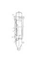
以下、本発明を図面に従って詳細に説明する。図1は、本発明の中空糸膜濾過装置の一例を示す縦断面図であり、図2は、図1の矢視の位置方向の横断面図である。
【0009】
図1において、濾過装置本体を構成する缶体容器1には、上部集水蓋2と底部斗3が取り付けられ、その内部には濾過膜である中空糸膜編織物の積層体4が配設されている。積層体4は、図に示すように中空糸膜編織物が互いに平行に配列されてなるものであり、各編織物は相互に密着するのではなく、ある程度の間隔を有していることが好ましく、配列の間隔は等しくするのが装置設計上並びに運転上からも好ましい。各中空糸膜編織物は、上部固定部材5と下部固定部材6によって配設位置が固定されている。配列の間隔は等しくするのが装置設計上並びに運転上からも好ましい。上部固定部材5は缶体容器に固着され、下部固定部材6は集水セルに接合されている。
【0010】
積層体4に用いる中空糸膜編織物は、通常は、中空糸膜が緯糸として用いられて編織された編物または織物であり、例えば特公平4−26886号、特開昭63ほ91673号に記載された方法により製造される。この編織物に用いる中空糸膜としては、ポリオレフィン系、ポリビニルアルコール系、ポリ(メタ)アクリル系、セルロース系、フッ素系等各種のものが使用できる。上部固定部材5と下部固定部材6には、例えばウレタン樹脂、エポキシ樹脂、不飽和ポリエステル樹脂あるいはこれらに熱可塑樹脂をブレンドしたものが使用できる。
【0011】
中空糸膜の開口端は、上部固定部材5および下部固定部材6の両方に形成され、中空糸膜で濾過された処理水は、上部開口端より出たものは上部集水蓋2中に集水され、下部開口端より出たものは集水セル7中に集水される。集水セル7は、下部固定部材6とはOリングなどのシール部材を介して液密にされて固設されている。上部集水蓋2の中の処理水は上部吐出口11から流出し、集水セル7中の処理水は、フレキシブルホースを介して缶体容器1に配設された下部吐出口10から流出する。
【0012】
集水セル7は、缶体容器1の内壁面から突出した支持部材8に取り付けられている調整ピン9により、その上下方向の位置を中空糸膜編織物の張力の状態が適正となるように調整して支持部材8に係着されている。支持部材8は、通常4個乃至8個取り付けられ(図2には4個の場合を示す)、集水セル7の周り、すなわちこれらの支持部材8の間を、濾過膜から脱落沈降する濾滓が通過する。支持部材8の間の通路を通過した濾滓は底部斗3に一旦集められ、随時排泥口15より排出される。
【0013】
被処理水は、図2に示したノズル取り付け口16に取り付けられた管体の先端部分に複数設けられた被処理水供給ノズル12より缶体容器内へ供給される。また、濾過膜面を洗浄するエアスクラビング用空気は、同じくノズル取り付け口16に取り付けられた管体の先端部分に複数設けられた散気ノズル13より放出される。被処理水供給ノズル12と散気ノズル13は、ともに積層体4の間に配置されているが、下部固定部材6の上面近傍に位置させることが重要であり、ノズルの先端が下部固定部材6の上面から10cm以内、好ましくは5cm以内に設置する。この例では被処理水ノズル12と散気ノズル13は上下二段に配設されているが、これらの上下位置関係はいずれでもよく、それぞれのノズルの流出孔は下方に向けて開口させる。被処理水の流出時の流動作用と空気の攪乱作用により下部固定部材6の上面は汚泥の沈積がなくなり、長期に亙っての正常な運転が可能となる。被処理水ノズル12と散気ノズル13は、積層体の両外側に追加して配設することもできる。
【0014】
濾過膜面をエアスクラビングして上昇した空気は、缶体容器1に配設された空気排出口14より流出する。上方に位置する濾過膜面迄充分に洗浄するために、上部固定部材5の積層体4との接合下面の位置は、空気排出口14の位置よりも低くするのが好ましい。
【0015】
第3図は、図1の中空糸膜濾過装置に案内筒を付設した中空糸膜濾過装置の他の例である。缶体容器と同軸の円筒状の案内筒17が、積層体4の周囲に付設されている。案内筒17を設けて缶体容器内が二重(円)筒状に仕切られることにより、エアスクラビング用の空気の上昇移動によって案内筒17の下端開口部18より被処理液が流入し、上端開口部19から流出し、更に案内筒17の外側を下降する随伴循環流が形成される。これによって濾過膜表面での被処理液の線流速が高くなり、一層効果的に濾過膜表面の洗浄を発現させることができる。案内筒の材質としては合成樹脂製のパイプを利用できるが、これは中空糸編織物の積層体を運搬する際の保護や缶体容器に収納装着する際の保護の目的をも果たすことができる。この例では、案内筒17は上部固定部材5に接合され、下部固定部材6との間には隙間を開けて接続固定されていないが、特にこの態様に限定されるものではない。
【0016】
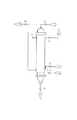
図4は本発明の中空糸膜濾過装置を用いた汚泥水等の濾過の装置囲りのフローシートである。被処理原水aはポンプで加圧されバルブV1 を経て被処理水供給ノズル12から缶体容器内へ供給され、本濾過装置により濾過されて下部吐出口10および上部吐出口11よりバルブV2 を経て処理水bとして取り出される。膜の目づまりが進行し、濾過圧力が所定値以上になると、バルブV1 、V2 を閉じ放流用のバルブV7 を開き次いでバルブV5 とV4 を開いて散気ノズル13より加圧空気dを供給し、エアスクラビングによる膜面洗浄を所定時間行う。排出空気eはバルブV5 を経て系外に排出される。その後バルブV4 、V5 を閉じバルブV2 、V1 を開いて再び濾過を行う。エアスクラビングによる膜面洗浄の繰り返し回数のある時期においては、逆通水fをバルブV6 を開け上部吐出口11を経て供給し膜面の洗浄回復を行うことができる。更にまたある時期においては汚泥cをバルブV3 を開き排泥口15より排出する。
【0017】
以上の操作により膜面の濾滓は除去され系外に排出され中空糸膜濾過装置内に蓄積することなく長期に亙って安定した運転が可能となる。
【0018】
【発明の効果】
本発明では、中空糸膜編織物の積層体の濾過膜を缶体容器に収納して使用するので濾過差圧を大きくでき、しかも積層体の上下両端部に固定部材を配設しているので中空糸内流路の圧損を小さくできるため、大きい透水量を確保することができる。また、被処理水ノズルと散気ノズルの少なくとも一方を下部固定部材の近傍の各積層体間にそれらの流出孔が下方に向けて開口するように配設したことにより、エアスクラビングによる中空糸膜の膜面洗浄を行っても下部固定部材上に濾滓汚泥の沈積が発生せず、かつ構造上逆通水も可能なので長期に亙って安定して運転することができる。また、案内筒を付設することによってエアスクラビングによる膜面洗浄をさらに効果的に行うこともできる。この中空糸膜濾過装置を複数基設置すれば間断なく連続して処理水を得ることができ、また透水量が大きいため設置面積当たりの処理水量が大きく水処理プラントとしての工業的有用性は極めて大きい。
【図面の簡単な説明】
【図1】本発明の中空糸膜濾過装置の一例を示した縦断面図である。
【図2】図1の矢視の位置方向の横断面図である。
【図3】案内筒を固定部材に付設した本発明の中空糸膜濾過装置の一例を示した縦断面図である。
【図4】本発明の中空糸膜濾過装置を使用して汚濁水を濾過する場合の該装置囲りのフローの説明図である。
【符号の説明】
1 缶体容器
2 上部集水蓋
3 底部斗
4 積層体
5 上部固定部材
6 下部固定部材
7 集水セル
8 支持部材
9 調整ピン
10 下部吐出口
11 上部吐出口
12 被処理水ノズル
13 散気ノズル
14 空気排出口
15 排泥口
16 ノズル取り付け口
17 案内筒
18 下端開口部
19 上端開口部
a 被処理原水
b 処理水
c 汚泥
d 加圧空気
e 排出空気
f 逆通水[0001]
BACKGROUND OF THE INVENTION
The present invention relates to a hollow fiber membrane filtration device, and more particularly to a hollow fiber membrane filtration device used when filtering a highly pollutant and highly viscous fluid. Specific application fields of the apparatus include dye filtration, liquor filtration, river water / lake water filtration, industrial water filtration, wastewater treatment, and the like.
[0002]
[Prior art]
As a filtration method of a device for filtering a highly pollutant, highly viscous fluid using a hollow fiber membrane, water to be treated is flowed to the outside of the hollow fiber membrane and the shearing action causes deposition of contaminants on the membrane surface. A cross flow method that filters part of the treated water while preventing it, and a total amount filtration method that filters all of the treated water while cleaning the membrane surface intermittently by air scrubbing, reverse water flow, reverse air flow, etc. It is used.
[0003]
Although the former is easy to operate, the energy consumption per amount of treated water is large due to the flow of treated water. On the other hand, the latter does not consume much energy, but special measures are required on the module structure to prevent membrane surface contamination and remove sludge. Specific examples thereof include modules described in JP-A-7-236817 and JP-A-7-1000048, in which a hollow fiber membrane is developed into a flat shape, immersed in an open water tank, and treated water is suction-filtered. Proposal of filtration devices using modules described in Japanese Patent Application Laid-Open No. 5-261254 and Japanese Patent Application No. 7-325274 that folds a knitted fabric in a zigzag shape or laminates and applies pressure to the water to be treated as a laminate. Has been.
[0004]
[Problems to be solved by the invention]
However, even in a filtration device of a total amount filtration method that consumes less energy per treated water volume, a filtration device that uses a module that is soaked and filtered by filtration cannot basically increase the filtration differential pressure above atmospheric pressure. Furthermore, since the pressure during reverse water flow and reverse air flow washing cannot be increased due to the structural design, a considerably large hollow fiber membrane area has to be incorporated in order to increase the amount of treated water.
[0005]
On the other hand, a filtration apparatus using a module configured to be stored in a container and pressurized and filtered can increase the filtration differential pressure, and can also increase the pressure at the time of reverse water flow and reverse aeration washing due to the structural design. On the other hand, from the viewpoint of cleaning by air scrubbing and sedimentation of pollutants, the lower end of the disposed hollow fiber membrane is a free end without providing a fixing member that forms an open end in the hollow fiber membrane, There was a restriction that the fixing member could be molded only at the end. Therefore, if the length of the laminate of hollow fiber membrane knitted fabric is increased due to pressure loss in the hollow fiber flow path, the efficiency of use of the membrane decreases, and as a result, the module length cannot be increased. The amount of treated water could not be increased.
[0006]
An object of the present invention is a filtration device of a total amount filtration method with a low energy cost per treated water using a hollow fiber membrane, having high membrane utilization efficiency, excellent membrane cleaning properties, and a problem in removing pollutants. It is providing the filtration apparatus which has the performance which there is no and installation area is small.
[0007]
[Means for Solving the Problems]
The present invention that achieves the above object is a hollow fiber membrane filtration apparatus in which a laminate of hollow fiber membrane knitted fabrics is arranged as a filtration membrane in a can body container, and the laminate is fixed to the upper and lower ends of the laminate. A fixing member forming the open end of the hollow fiber membrane is disposed, the upper fixing member is fixed to the can body container, the lower fixing member is joined to a water collection cell communicating with the treated water outlet, and the water collection cell is filtered. An untreated water supply nozzle and / or between each laminated body in the vicinity of the upper surface of the lower fixing member that is engaged with the can body container while forming a passage through which the soot passes between the inner wall surface of the can body container. Or it is a hollow fiber membrane filtration apparatus characterized by arrange | positioning an aeration nozzle so thateach outflow hole may open toward the downward direction .
[0008]
DETAILED DESCRIPTION OF THE INVENTION
Hereinafter, the present invention will be described in detail with reference to the drawings. FIG. 1 is a longitudinal sectional view showing an example of the hollow fiber membrane filtration device of the present invention, and FIG. 2 is a transverse sectional view in the position direction of the arrow in FIG.
[0009]
In FIG. 1, an upper
[0010]
The hollow fiber membrane knitted fabric used for the
[0011]
The open end of the hollow fiber membrane is formed in both the
[0012]
The
[0013]
To-be-treated water is supplied into the can body container from the to-be-treated
[0014]
The air that has risen as a result of air scrubbing the filtration membrane surface flows out from the air discharge port 14 provided in the
[0015]
FIG. 3 is another example of a hollow fiber membrane filtration device in which a guide tube is attached to the hollow fiber membrane filtration device of FIG. A
[0016]
FIG. 4 is a flow sheet surrounding a device for filtering sludge water or the like using the hollow fiber membrane filtration device of the present invention. The raw water a to be treated is pressurized by a pump, supplied to the can body container from the treated
[0017]
By the above operation, the filter cake on the membrane surface is removed, discharged outside the system, and accumulated in the hollow fiber membrane filtration device, enabling stable operation over a long period of time.
[0018]
【The invention's effect】
In the present invention, the filtration membrane of the laminate of hollow fiber membrane knitted fabrics is housed in a can body container so that the filtration differential pressure can be increased, and the fixing members are disposed at the upper and lower ends of the laminate. Since the pressure loss of the flow path in the hollow fiber can be reduced, a large amount of water permeability can be secured. In addition, a hollow fiber membrane by air scrubbing is provided by disposing at least one of the water nozzle to be treated and the aeration nozzle so thatthe outflow holes thereof open downward between the respective laminated bodies in the vicinity of the lower fixing member. Even if this membrane surface cleaning is performed, no sedimentation of the filter sludge is generated on the lower fixing member, and since reverse water flow is possible due to the structure, it is possible to operate stably over a long period of time. Moreover, the film surface cleaning by air scrubbing can be performed more effectively by providing a guide tube. By installing a plurality of these hollow fiber membrane filtration devices, treated water can be obtained continuously without interruption, and since the amount of water permeation is large, the amount of treated water per installation area is large and the industrial utility as a water treatment plant is extremely high. large.
[Brief description of the drawings]
FIG. 1 is a longitudinal sectional view showing an example of a hollow fiber membrane filtration device of the present invention.
2 is a cross-sectional view in the position direction of the arrow in FIG.
FIG. 3 is a longitudinal sectional view showing an example of the hollow fiber membrane filtration device of the present invention in which a guide tube is attached to a fixing member.
FIG. 4 is an explanatory diagram of a flow around the apparatus when the contaminated water is filtered using the hollow fiber membrane filtration apparatus of the present invention.
[Explanation of symbols]
DESCRIPTION OF
Claims (2)
Translated fromJapanesePriority Applications (1)
| Application Number | Priority Date | Filing Date | Title |
|---|---|---|---|
| JP15841697AJP3859816B2 (en) | 1997-06-16 | 1997-06-16 | Hollow fiber membrane filtration device |
Applications Claiming Priority (1)
| Application Number | Priority Date | Filing Date | Title |
|---|---|---|---|
| JP15841697AJP3859816B2 (en) | 1997-06-16 | 1997-06-16 | Hollow fiber membrane filtration device |
Publications (2)
| Publication Number | Publication Date |
|---|---|
| JPH115023A JPH115023A (en) | 1999-01-12 |
| JP3859816B2true JP3859816B2 (en) | 2006-12-20 |
Family
ID=15671285
Family Applications (1)
| Application Number | Title | Priority Date | Filing Date |
|---|---|---|---|
| JP15841697AExpired - LifetimeJP3859816B2 (en) | 1997-06-16 | 1997-06-16 | Hollow fiber membrane filtration device |
Country Status (1)
| Country | Link |
|---|---|
| JP (1) | JP3859816B2 (en) |
Families Citing this family (27)
| Publication number | Priority date | Publication date | Assignee | Title |
|---|---|---|---|---|
| TWI222895B (en)* | 1998-09-25 | 2004-11-01 | Usf Filtration & Separations | Apparatus and method for cleaning membrane filtration modules |
| AUPS300602A0 (en) | 2002-06-18 | 2002-07-11 | U.S. Filter Wastewater Group, Inc. | Methods of minimising the effect of integrity loss in hollow fibre membrane modules |
| NZ545206A (en) | 2003-08-29 | 2009-03-31 | Siemens Water Tech Corp | Backwash |
| NZ553771A (en) | 2004-09-15 | 2010-11-26 | Siemens Water Tech Corp | Continuously variable aeration of membrane filtration system and flow control device when used in such application |
| JP2006116495A (en)* | 2004-10-25 | 2006-05-11 | Sumitomo Electric Fine Polymer Inc | Filter device |
| JP4906269B2 (en)* | 2005-04-27 | 2012-03-28 | 前澤工業株式会社 | Filtration device |
| JP2008539054A (en) | 2005-04-29 | 2008-11-13 | シーメンス・ウォーター・テクノロジーズ・コーポレイション | Chemical cleaning for membrane filters |
| US8858796B2 (en) | 2005-08-22 | 2014-10-14 | Evoqua Water Technologies Llc | Assembly for water filtration using a tube manifold to minimise backwash |
| US8293098B2 (en) | 2006-10-24 | 2012-10-23 | Siemens Industry, Inc. | Infiltration/inflow control for membrane bioreactor |
| US8318028B2 (en) | 2007-04-02 | 2012-11-27 | Siemens Industry, Inc. | Infiltration/inflow control for membrane bioreactor |
| US9764288B2 (en) | 2007-04-04 | 2017-09-19 | Evoqua Water Technologies Llc | Membrane module protection |
| CA2688455C (en) | 2007-05-29 | 2019-12-03 | Siemens Water Technologies Corp. | Pulsed random two phase gas/liquid flow for cleaning membrane surfaces |
| WO2010009518A1 (en) | 2008-07-24 | 2010-01-28 | Siemens Water Technologies Corp. | Frame system for membrane filtration modules |
| KR100999038B1 (en) | 2008-08-01 | 2010-12-09 | (주)필로스 | Membrane module |
| AU2010101488B4 (en) | 2009-06-11 | 2013-05-02 | Evoqua Water Technologies Llc | Methods for cleaning a porous polymeric membrane and a kit for cleaning a porous polymeric membrane |
| KR101180722B1 (en)* | 2010-01-28 | 2012-09-10 | 웅진코웨이주식회사 | Hollow fiber membrane module |
| WO2011136888A1 (en) | 2010-04-30 | 2011-11-03 | Siemens Industry, Inc | Fluid flow distribution device |
| WO2012040412A1 (en) | 2010-09-24 | 2012-03-29 | Siemens Industry, Inc. | Fluid control manifold for membrane filtration system |
| WO2013048801A1 (en) | 2011-09-30 | 2013-04-04 | Siemens Industry, Inc. | Improved manifold arrangement |
| KR102177864B1 (en) | 2011-09-30 | 2020-11-13 | 에보쿠아 워터 테크놀로지스 엘엘씨 | Isolation valve |
| WO2014004645A1 (en) | 2012-06-28 | 2014-01-03 | Siemens Industry, Inc. | A potting method |
| AU2013231145B2 (en) | 2012-09-26 | 2017-08-17 | Evoqua Water Technologies Llc | Membrane potting methods |
| DE112013004713T5 (en) | 2012-09-26 | 2015-07-23 | Evoqua Water Technologies Llc | Membrane safety device |
| AU2013323934A1 (en) | 2012-09-27 | 2015-02-26 | Evoqua Water Technologies Llc | Gas scouring apparatus for immersed membranes |
| EP3052221B1 (en) | 2013-10-02 | 2022-12-14 | Rohm & Haas Electronic Materials Singapore Pte. Ltd | Device for repairing a membrane filtration module |
| US10322375B2 (en) | 2015-07-14 | 2019-06-18 | Evoqua Water Technologies Llc | Aeration device for filtration system |
| CN116099368B (en)* | 2023-04-11 | 2023-10-03 | 利得膜(北京)新材料技术有限公司 | External pressure type filter |
- 1997
- 1997-06-16JPJP15841697Apatent/JP3859816B2/ennot_activeExpired - Lifetime
Also Published As
| Publication number | Publication date |
|---|---|
| JPH115023A (en) | 1999-01-12 |
Similar Documents
| Publication | Publication Date | Title |
|---|---|---|
| JP3859816B2 (en) | Hollow fiber membrane filtration device | |
| KR100326739B1 (en) | Hollow Fiber Membrane Module, Hollow Fiber Membrane Module Unit Using the Same, and Septic Tank Provided with the Module Unit | |
| JP4230569B2 (en) | Hollow fiber membrane module | |
| CN101500681A (en) | High flow disc filter | |
| KR100646001B1 (en) | Immersion type filtration device and system using hollow fiber membrane module | |
| CN105246570B (en) | Filtration device, ballast water treatment method, and ballast water treatment equipment using the filtration device | |
| US20210060465A1 (en) | Retrofitting and use of rectangular filters, assembly and method for filtration | |
| CN105813720A (en) | Immersion filter | |
| JP4454091B2 (en) | Spiral membrane module and spiral membrane element loading method | |
| JPH10216419A (en) | Sewage cleaning device | |
| JP2000300964A (en) | Hollow fiber membrane module | |
| KR100274759B1 (en) | Microfiltration method and system using textile hose | |
| KR200420112Y1 (en) | Immersion type filtration device for water treatment | |
| KR101884307B1 (en) | Submerged filtration system with backwash system using compressed air | |
| KR101130918B1 (en) | A water treatment system by non-efflux self-weight water pressure filteration using elvan | |
| JP3486308B2 (en) | Membrane processing equipment | |
| CN221544230U (en) | Integrated automatic water purifying equipment | |
| JP4217281B2 (en) | Septic tank | |
| JPWO2007122918A1 (en) | Water treatment equipment | |
| WO2009128119A1 (en) | Method of cleaning membrane module and apparatus therefor | |
| KR100718791B1 (en) | Immersion type filtration device for water treatment | |
| RU30286U1 (en) | Liquid Purifier | |
| JP7705754B2 (en) | Wastewater treatment device and method for cleaning the same | |
| JPH08229360A (en) | Membrane module | |
| KR101960775B1 (en) | Submerged-Type Filtration Apparatus |
Legal Events
| Date | Code | Title | Description |
|---|---|---|---|
| A977 | Report on retrieval | Free format text:JAPANESE INTERMEDIATE CODE: A971007 Effective date:20050307 | |
| A131 | Notification of reasons for refusal | Free format text:JAPANESE INTERMEDIATE CODE: A131 Effective date:20050316 | |
| A521 | Written amendment | Free format text:JAPANESE INTERMEDIATE CODE: A523 Effective date:20050512 | |
| RD03 | Notification of appointment of power of attorney | Free format text:JAPANESE INTERMEDIATE CODE: A7423 Effective date:20050512 | |
| TRDD | Decision of grant or rejection written | ||
| A01 | Written decision to grant a patent or to grant a registration (utility model) | Free format text:JAPANESE INTERMEDIATE CODE: A01 Effective date:20060906 | |
| A61 | First payment of annual fees (during grant procedure) | Free format text:JAPANESE INTERMEDIATE CODE: A61 Effective date:20060920 | |
| FPAY | Renewal fee payment (event date is renewal date of database) | Free format text:PAYMENT UNTIL: 20100929 Year of fee payment:4 | |
| FPAY | Renewal fee payment (event date is renewal date of database) | Free format text:PAYMENT UNTIL: 20110929 Year of fee payment:5 | |
| FPAY | Renewal fee payment (event date is renewal date of database) | Free format text:PAYMENT UNTIL: 20110929 Year of fee payment:5 | |
| FPAY | Renewal fee payment (event date is renewal date of database) | Free format text:PAYMENT UNTIL: 20110929 Year of fee payment:5 | |
| FPAY | Renewal fee payment (event date is renewal date of database) | Free format text:PAYMENT UNTIL: 20120929 Year of fee payment:6 | |
| S531 | Written request for registration of change of domicile | Free format text:JAPANESE INTERMEDIATE CODE: R313531 | |
| FPAY | Renewal fee payment (event date is renewal date of database) | Free format text:PAYMENT UNTIL: 20120929 Year of fee payment:6 | |
| R350 | Written notification of registration of transfer | Free format text:JAPANESE INTERMEDIATE CODE: R350 | |
| FPAY | Renewal fee payment (event date is renewal date of database) | Free format text:PAYMENT UNTIL: 20130929 Year of fee payment:7 | |
| R250 | Receipt of annual fees | Free format text:JAPANESE INTERMEDIATE CODE: R250 | |
| R250 | Receipt of annual fees | Free format text:JAPANESE INTERMEDIATE CODE: R250 | |
| R250 | Receipt of annual fees | Free format text:JAPANESE INTERMEDIATE CODE: R250 | |
| R250 | Receipt of annual fees | Free format text:JAPANESE INTERMEDIATE CODE: R250 | |
| EXPY | Cancellation because of completion of term |