JP3855870B2 - Portable power system - Google Patents
Portable power systemDownload PDFInfo
- Publication number
- JP3855870B2 JP3855870B2JP2002206795AJP2002206795AJP3855870B2JP 3855870 B2JP3855870 B2JP 3855870B2JP 2002206795 AJP2002206795 AJP 2002206795AJP 2002206795 AJP2002206795 AJP 2002206795AJP 3855870 B2JP3855870 B2JP 3855870B2
- Authority
- JP
- Japan
- Prior art keywords
- terminal
- battery pack
- discharge
- power supply
- portable power
- Prior art date
- Legal status (The legal status is an assumption and is not a legal conclusion. Google has not performed a legal analysis and makes no representation as to the accuracy of the status listed.)
- Expired - Fee Related
Links
Images


Classifications
- B—PERFORMING OPERATIONS; TRANSPORTING
- B62—LAND VEHICLES FOR TRAVELLING OTHERWISE THAN ON RAILS
- B62M—RIDER PROPULSION OF WHEELED VEHICLES OR SLEDGES; POWERED PROPULSION OF SLEDGES OR SINGLE-TRACK CYCLES; TRANSMISSIONS SPECIALLY ADAPTED FOR SUCH VEHICLES
- B62M6/00—Rider propulsion of wheeled vehicles with additional source of power, e.g. combustion engine or electric motor
- B62M6/80—Accessories, e.g. power sources; Arrangements thereof
- B62M6/90—Batteries
- H—ELECTRICITY
- H01—ELECTRIC ELEMENTS
- H01M—PROCESSES OR MEANS, e.g. BATTERIES, FOR THE DIRECT CONVERSION OF CHEMICAL ENERGY INTO ELECTRICAL ENERGY
- H01M10/00—Secondary cells; Manufacture thereof
- H01M10/42—Methods or arrangements for servicing or maintenance of secondary cells or secondary half-cells
- H01M10/44—Methods for charging or discharging
- H01M10/443—Methods for charging or discharging in response to temperature
- H—ELECTRICITY
- H01—ELECTRIC ELEMENTS
- H01M—PROCESSES OR MEANS, e.g. BATTERIES, FOR THE DIRECT CONVERSION OF CHEMICAL ENERGY INTO ELECTRICAL ENERGY
- H01M10/00—Secondary cells; Manufacture thereof
- H01M10/60—Heating or cooling; Temperature control
- H01M10/62—Heating or cooling; Temperature control specially adapted for specific applications
- H01M10/623—Portable devices, e.g. mobile telephones, cameras or pacemakers
- H01M10/6235—Power tools
- H—ELECTRICITY
- H01—ELECTRIC ELEMENTS
- H01M—PROCESSES OR MEANS, e.g. BATTERIES, FOR THE DIRECT CONVERSION OF CHEMICAL ENERGY INTO ELECTRICAL ENERGY
- H01M10/00—Secondary cells; Manufacture thereof
- H01M10/60—Heating or cooling; Temperature control
- H01M10/62—Heating or cooling; Temperature control specially adapted for specific applications
- H01M10/625—Vehicles
- H—ELECTRICITY
- H01—ELECTRIC ELEMENTS
- H01M—PROCESSES OR MEANS, e.g. BATTERIES, FOR THE DIRECT CONVERSION OF CHEMICAL ENERGY INTO ELECTRICAL ENERGY
- H01M10/00—Secondary cells; Manufacture thereof
- H01M10/60—Heating or cooling; Temperature control
- H01M10/63—Control systems
- H01M10/637—Control systems characterised by the use of reversible temperature-sensitive devices, e.g. NTC, PTC or bimetal devices; characterised by control of the internal current flowing through the cells, e.g. by switching
- H—ELECTRICITY
- H01—ELECTRIC ELEMENTS
- H01M—PROCESSES OR MEANS, e.g. BATTERIES, FOR THE DIRECT CONVERSION OF CHEMICAL ENERGY INTO ELECTRICAL ENERGY
- H01M50/00—Constructional details or processes of manufacture of the non-active parts of electrochemical cells other than fuel cells, e.g. hybrid cells
- H01M50/20—Mountings; Secondary casings or frames; Racks, modules or packs; Suspension devices; Shock absorbers; Transport or carrying devices; Holders
- H01M50/204—Racks, modules or packs for multiple batteries or multiple cells
- H01M50/207—Racks, modules or packs for multiple batteries or multiple cells characterised by their shape
- H01M50/213—Racks, modules or packs for multiple batteries or multiple cells characterised by their shape adapted for cells having curved cross-section, e.g. round or elliptic
- Y—GENERAL TAGGING OF NEW TECHNOLOGICAL DEVELOPMENTS; GENERAL TAGGING OF CROSS-SECTIONAL TECHNOLOGIES SPANNING OVER SEVERAL SECTIONS OF THE IPC; TECHNICAL SUBJECTS COVERED BY FORMER USPC CROSS-REFERENCE ART COLLECTIONS [XRACs] AND DIGESTS
- Y02—TECHNOLOGIES OR APPLICATIONS FOR MITIGATION OR ADAPTATION AGAINST CLIMATE CHANGE
- Y02E—REDUCTION OF GREENHOUSE GAS [GHG] EMISSIONS, RELATED TO ENERGY GENERATION, TRANSMISSION OR DISTRIBUTION
- Y02E60/00—Enabling technologies; Technologies with a potential or indirect contribution to GHG emissions mitigation
- Y02E60/10—Energy storage using batteries
- Y—GENERAL TAGGING OF NEW TECHNOLOGICAL DEVELOPMENTS; GENERAL TAGGING OF CROSS-SECTIONAL TECHNOLOGIES SPANNING OVER SEVERAL SECTIONS OF THE IPC; TECHNICAL SUBJECTS COVERED BY FORMER USPC CROSS-REFERENCE ART COLLECTIONS [XRACs] AND DIGESTS
- Y02—TECHNOLOGIES OR APPLICATIONS FOR MITIGATION OR ADAPTATION AGAINST CLIMATE CHANGE
- Y02P—CLIMATE CHANGE MITIGATION TECHNOLOGIES IN THE PRODUCTION OR PROCESSING OF GOODS
- Y02P70/00—Climate change mitigation technologies in the production process for final industrial or consumer products
- Y02P70/50—Manufacturing or production processes characterised by the final manufactured product
Landscapes
- Engineering & Computer Science (AREA)
- Chemical & Material Sciences (AREA)
- Electrochemistry (AREA)
- General Chemical & Material Sciences (AREA)
- Chemical Kinetics & Catalysis (AREA)
- Manufacturing & Machinery (AREA)
- Combustion & Propulsion (AREA)
- Biophysics (AREA)
- Life Sciences & Earth Sciences (AREA)
- Automation & Control Theory (AREA)
- Transportation (AREA)
- Mechanical Engineering (AREA)
- Battery Mounting, Suspending (AREA)
- Charge And Discharge Circuits For Batteries Or The Like (AREA)
- Secondary Cells (AREA)
- Connection Of Batteries Or Terminals (AREA)
Description
Translated fromJapanese【0001】
【発明の属する技術分野】
本発明は、ポータブル電源システムに関し、特に、電源使用機器本体と電池パックとの装着構造に関するものである。
【0002】
【従来の技術】
従来、ポータブル電源システムを使用した電源使用機器の一例には、ねじ締め作業に使われる電動ドライバー等の電動工具がある。この電動工具は、作業効率が飛躍的に向上するために、主に、業務用として建築現場などで使われていた。近年では、ホームセンター等で売られ、日曜大工用に一般にも使われるようになってきた。
【0003】
作業現場などでは、まだ電気が配線されていない場合があり、またコードなどがあると作業性が悪くなるため、ドライバー等の比較的低消費電力の電動工具には、電源として複数個の二次電池から構成される電池パックが、一般に使われる。この電池パックは通常、交換可能になっており、充電は、電池パックを専用の充電器に嵌め込むことで行なう。作業現場などでは、予備の交換用電池パックを用意して、作業途中に電池の容量が無くなった時には、電池パックを交換して作業を続けることがよく行われている。
【0004】
従来の電池パックの一例として、松下電工製の電動工具(DRILL&DRIVER 型番EZ6225)の電池パック(型番EZ9025)について、図15から図17を用いて説明する。
【0005】
図15は、電池パック(EZ9025)の斜視図であり、図16は、その上面図である。電池パックが電動工具本体に、挿入される時はガイド1によって位置決めされつつ挿入され、ラッチ2で固定される。電池パックの上端には、充放電兼用の正極端子3、充電専用の充電負極端子4、放電専用の放電負極端子5およびサーミスタ端子6が、剥き出しの状態で設置されている。
【0006】
図17に、電池パック(EZ9025)の回路図を示す。正極端子3、二次電池7および放電負極端子5からなる放電回路には、電流規制素子が備えられていないが、正極端子3、二次電池7および充電負極端子4からなる充電回路には、制御回路8およびサーマルプロテクタ9が備えられており、充電時の安全性を確保している。さらにサーミスタ端子6には、サーミスタ10が接続されており、充電時には、このサーミスタ10の抵抗値により電池パックの温度をモニターして、充電を制御している。従来の電池パックにおいては、充電回路には、充電時に万が一、充電器が故障した場合、電流が流れつづけるため電池パック側にも電流規制素子が備えられている。しかし、放電回路に関しては、使用時に一時的に大電流が流れる場合があること、放電電流の総量は二次電池の容量で規制されることなどから電流規制素子は備えられていない。
【0007】
以上述べた、正極端子などの外部端子を、電池パックを落下させた時などの外部衝撃から保護するために、外部端子を蓋体の空洞部に面する内周側の部位に設けることで、外部衝撃から外部端子を保護すると共に、外部から外部端子に接触しがたい構造としたものが提案されている(特開2001−135287号公報)。
【0008】
【発明が解決しようとする課題】
しかしながら、この電池パックにおいても、外部端子は内側にあるとはいえ、依然剥き出しのままであり、自動車用バッテリーなどの大型バッテリーなどからリードを用いて充電することが可能であった。この場合に、放電端子側から充電されると、電流規制素子が無いため非常に危険であるという課題があった。
【0009】
本発明は上記課題に鑑みてなされたものであり、電源使用機器本体を使用した場合のみ放電端子と接続できる装着構造を簡易な構成で提供することを目的とするものである。
【0010】
【課題を解決するための手段】
上記課題を解決するために、本発明では、電源使用機器本体と電池パックの装着構造において、装着構造は、前記電源使用機器本体の外部端子が凸型で、前記電池パックの放電端子が凹型で剥き出しになっておらず、前記電池パックの放電端子に、前記外部端子を挿入しただけでは接続されず、前記外部端子を挿入後回転させるか、又は前記外部端子を挿入後、挿入方向と違う方向にスライドさせることで接続するというダブルアクション機構からなることを特徴とする。
【0011】
これにより、電池パックの放電端子には、電源使用機器本体を使用しない場合には、リード等を接続できないように出来る。
【0012】
【発明の実施の形態】
本発明の請求項1に記載の発明は、複数個の二次電池から構成される電池パックを電源とし、電源使用機器本体と前記電池パックが、装着構造によって交換可能に接続されたポータブル電源システムにおいて、前記電池パックは、充電端子を持つ充電回路と放電端子を持つ放電回路をそれぞれ備え、前記充電回路には、充電時の電圧および電流を制御する制御回路を備えており、前記装着構造は、前記電源使用機器本体の外部端子が凸型で、前記電池パックの放電端子が凹型で剥き出しになっておらず、前記電池パックの放電端子に、前記外部端子を挿入しただけでは接続されず、前記外部端子を挿入後回転させるか、又は前記外部端子を挿入後、挿入方向と違う方向にスライドさせることで接続するというダブルアクション機構からなることを特徴とするポータブル電源システムとしたものである。
【0013】
この構成においては、電池パックの放電端子が凹型であるため、剥き出しになっておらず、端子に嵌合する凸型の部品を挿入しただけでは接続されず、接続するためには、さらに回転させるか挿入方向と違う方向にスライドさせるというダブルアクション機構が採用されているため、放電端子から充電するという危険行為が防止されている。
【0014】
本発明の請求項2に記載の発明は、請求項1記載のポータブル電源システムにおいて、前記二次電池がリチウムイオン二次電池であることを特徴としたものであり、過充電に弱いリチウムイオン二次電池を保護できるという作用を有する。
【0015】
本発明の請求項3に記載の発明は、請求項1記載のポータブル電源システムにおいて、前記充電回路には制御回路に加え、サーマルプロテクターを備え、前記放電回路にはあらゆる種類の電流規制素子を備えないことを特徴としたものであり、充電端子が剥き出しであり、そこからリード等で充電されたときでも安全を確保できるという作用を有する。このサーマルプロテクターには、サーモスタット、PTC素子、温度ヒューズなど、従来公知のものが使える。
【0016】
特に、二次電池がリチウムイオン二次電池の時には、従来構成では電流規制素子が必要なので、本構成のように放電回路に電流規制素子を備えないで大電流が使えるメリットは大きい。
【0017】
本発明の請求項4に記載の発明は、請求項1記載のポータブル電源システムにおいて、前記充電端子と前記放電端子において、負極端子は電気的に独立しており、正極端子は同電位で共通な兼用端子となっており、さらに電池パックの温度測定用のサーミスタ端子からなることを特徴としたものである。この構成では、正極端子は共通なため、加工等のコストを削減することができる。さらに、サーミスタ端子が備えられているため、充電時の電池パックの温度を測定しながら充電することができる。
【0018】
本発明の請求項5に記載の発明は、請求項1記載のポータブル電源システムにおいて、放電用の負極端子と正極端子の構造のみが凹型であり、かつダブルアクション機構からなる装着構造である。つまり、充電用の正極端子と負極端子は、従来の剥き出しの構造であるため、挿入のみのシングルアクションで充電器の端子と接続できるため好ましい。この時、正極端子は、放電用の放電正極端子と同電位で、共通な兼用端子となっていても構わない。具体的な実施の形態としては、端子を構成する金属板の先端部がL型で端子用溝の凹部の非可視部にあり、ダブルアクション機構を有する放電正極端子となり、金属板の途中が剥き出しになり充電正極端子となる構成がある。この構成によると、二次電池からのリードと金属板が一つですむという効果がある。
【0019】
【実施例】
以下、本発明の具体例について図面を参照しながら説明する。
【0020】
(実施例1)
本実施例1においては、外部端子を挿入後回転させるダブルアクション機構を電動工具である電動ドライバーに実施した例を示す。
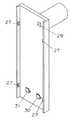
【0021】
図1は、本実施例の電池パックの斜視図であり、図2は、その上面図である。さらに図3は、本実施例の電動工具本体の斜視図である。図3において、電動工具本体は、ドライバービット11、駆動部12および電池パック保持部13からなっており、図4は、その電池パック保持部13の縦断面図である。図3において電源スイッチ、切替スイッチなどは本発明の要部ではないので、図示を省略している。
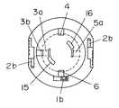
【0022】
最後に図5は、電動工具本体に電池パックを接続したときの電池パック保持部13の縦断面図である。
【0023】
本電池パックでは、逆接防止用のガイド1b、1cは、位置決めの他に、挿入後、右回りに回転するというダブルアクション機構を、確実に行なえるよう電動工具本体のガイド溝14に添って移動するようになっている。ラッチ2bも同様に、挿入しただけでなく、右回りに回転させるとカチッとはまるようになっている。
【0024】
電池パックの上端には、ダブルアクション機構で接続するようになっている放電正極端子用溝15および放電負極端子用溝16と内部に隠された金属板からなる放電正極端子3aおよび放電負極端子5aがあり、従来どおりの挿入のみで接続する充電正極端子3bおよび充電負極端子4がある。ここで、充電正極端子3bは、放電正極端子3aの金属板の途中が剥き出しになったものであり、同電位でお互いがつながっているものである。本電池パックにおいてもサーミスタを内蔵し、そのサーミスタ端子6が備わっている。
【0025】
図4に示すとおり、電動工具本体側の正極端子17および負極端子18は、L型になっており、放電正極端子用溝15および放電負極端子用溝16の広いほうにまず挿入され、その後の回転により、幅の狭いところに設置されている放電正極端子3aおよび放電負極端子5aと図5のように接続する。ここで、接触不良が起こらないようにばね19で、確実に端子同士を接触させる。
【0026】
なお、本電池パックは、二次電池7以外に制御回路、サーミスタおよびサーマルプロテクタを内蔵しており、それらを一つのプリント基板上に載せた内部回路20の配線は図17に示した従来の電池パックのものと同じである。
【0027】
本実施例においては、図2から明らかなように、放電正極端子3aおよび放電用負極端子5aは、外部から完全に隠れているので、リードを接続することができない。したがって、自動車用バッテリーなどの大型バッテリーなどからリードを用いて充電することは、不可能である。
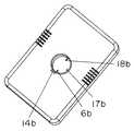
【0028】
図6に、本実施例の充電器の斜視図を示す。図6において電源スイッチ、充電状態表示ランプなどは本発明の要部ではないので、図示を省略している。図6において、17bは正極端子、18bは、負極端子、6bはサーミスタ端子であり、14bのガイド溝に電池パックのガイド1bを嵌合させて、電池パックを充電器に挿入したとき、正極端子3b、充電負極端子4、サーミスタ端子6とそれぞれ接続するようになっている。
【0029】
以上述べたとおり、本実施例においては、挿入のみのシングルアクションで充電器の端子と接続できるため、操作が容易であるという効果を有する。
【0030】
なお、本実施例においては、電動工具を例に挙げたが、電源使用機器が電気掃除機であっても、電池パック保持部の構造を本実施例の場合と同じようにすれば、本発明の電動工具と同じ作用効果が得られる。
【0031】
(実施例2)
本実施例2においては、外部端子を挿入後、挿入方向と直角方向にスライドさせるダブルアクション機構を電動自転車に実施した例を示す。
【0032】
図7は、本実施例の電動自転車の側面図である。サドル21を支えるシートチューブ22の背面に電池パック23が取付部24に配置されている。電池パック23の取り外しには、盗難防止のために鍵25を使うようになっている。
【0033】
図8は、本実施例の電池パック23の斜視図であり、図9は、取付部24の斜視図である。電池パック23の長側面には、それぞれガイド溝26があり、取付部24のガイド27により、まず取付面に垂直に電池パック23を取り付け、その後、取付面に平行にスライドさせるというダブルアクション機構による固定を実現している。さらに、電池パック23の底面には、充電正極端子用凹部28a、充電負極端子用凹部28b、サーミスタ端子用凹部28c、放電正極端子用凹部28d、放電負極端子用凹部28eおよびロック用凹部28fの合計6個の凹部がある。また、取付部24の取付面には、フック用窓29と、形状がL型の正極端子30および負極端子31がある。
【0034】
図10は、本実施例の電池パック23の底面図である。また、図11は、図10のA−A線断面図である。充電正極端子用凹部28a、充電負極端子用凹部28bおよびサーミスタ端子用凹部28cの3つ凹部の底面には、端子が剥き出しになっている。放電正極端子用凹部28dおよび放電負極端子用凹部28eには、目隠し板32があり、それぞれ放電正極端子33および放電負極端子34が、剥き出しにならないようにしている。ロック用凹部28fには、しきり35で、二つの部分に分けられている。
【0035】
この電池パック23を電動自転車に取り付けた場合について、さらに図12から図14を用いて詳細に説明する。
【0036】
図12は、電池パック23を取付部24に取り付けた時の上面図である。この図において、ガイド溝26およびガイド27は嵌合しており、図示を省略している。図13は、図12のB−B線断面図であり、図14(a)は、C−C線断面図、図14(b)はD−D線断面図である。
【0037】
図13において、ロック機構36は、ばね37に支えられたシリンダ38とフック39からなり、電池パック23のスライドによりフック39がしきり35を乗り越えると固定され、鍵25でロックできるようになる。電池パック23の放電正極端子33と取付部24の正極端子30は、電池パック23を最初に挿入した時は接続されていないが、その後のスライドで接続し、ロック機構36により固定した接続が得られる。図14(b)に示すように放電負極端子34と負極端子31も同様のダブルアクション機構により接続するようになっている。図14(a)に示すように充電用に使われるサーミスタ端子40および充電正極端子41等は、そのまま蓋をされている。
【0038】
本実施例においても、図13および14から明らかなように、放電正極端子33および放電用負極端子34は、外部から完全に隠れているので、リードを接続することができない。したがって、自動車用バッテリーなどの大型バッテリーなどからリードを用いて充電することは、不可能である。
【0039】
なお、本実施例においては、電動自転車を例に挙げたが、電源使用機器が電気バイクであっても、電池パック保持部の構造を本実施例の場合と同じようにすれば、本発明の電動自転車と同じ作用効果が得られる。
【0040】
【発明の効果】
以上のように、本発明のポータブル電源システムによれば、放電端子が完全に隠れており、ダブルアクション機構により、電源使用機器本体を使用した場合のみ放電端子と接続できる装着構造を提供することを可能とするものである。
【図面の簡単な説明】
【図1】本実施例1の電池パックの斜視図
【図2】本実施例1の電池パックの上面図
【図3】本実施例1の電動工具本体の斜視図
【図4】本実施例1の電池パック保持部13の縦断面図
【図5】電動工具本体に電池パックを接続した時の電池パック保持部13の縦断面図
【図6】本実施例1の充電器の斜視図
【図7】本実施例2の電動自転車の側面図
【図8】本実施例2の電池パック23の斜視図
【図9】本実施例2の取付部24の斜視図
【図10】本実施例2の電池パック23の底面図
【図11】図10のA−A線断面図
【図12】電池パック23を取付部24に取り付けた時の上面図
【図13】図12のB−B線断面図
【図14】(a)図12のC−C線断面図(b)図12のD−D線断面図
【図15】電池パック(EZ9025)の斜視図
【図16】電池パック(EZ9025)の上面図
【図17】電池パック(EZ9025)の回路図
【符号の説明】
1、1b、1c ガイド
2、2b ラッチ
3、3a 正極端子
3b 充電正極端子
4 充電負極端子
5、5a 放電負極端子
6、6b サーミスタ端子
7 二次電池
8 制御回路
9 サーマルプロテクタ
10 サーミスタ
11 ドライバービット
12 駆動部
13 電池パック保持部
14 ガイド溝
15 放電正極端子溝
16 放電負極端子溝
17、17b 正極端子
18、18b 負極端子
19 ばね
20 内部回路
21 サドル
22 シートチューブ
23 電池パック
24 取付部
25 鍵
26 ガイド溝
27 ガイド
28a,28b、28c、28d、28e、28f 凹部
29 フック用窓
30 正極端子
31 負極端子
32 目隠し板
33 放電正極端子
34 放電負極端子
35 しきり
36 ロック機構
37 ばね
38 シリンダ
39 フック
40 サーミスタ端子
41 充電正極端子[0001]
BACKGROUND OF THE INVENTION
The present invention relates to a portable power supply system, and more particularly, to a mounting structure between a power supply device main body and a battery pack.
[0002]
[Prior art]
Conventionally, an example of a power-consuming device using a portable power system is an electric tool such as an electric screwdriver used for screw tightening work. This power tool has been used mainly on construction sites for business purposes in order to dramatically improve work efficiency. In recent years, it has been sold at home centers, etc., and has come to be used generally for do-it-yourself carpenters.
[0003]
At work sites, etc., there may be cases where electricity is not yet wired, and the presence of cords will reduce the workability. Therefore, power tools with relatively low power consumption such as drivers have multiple secondary power sources. A battery pack composed of batteries is generally used. This battery pack is normally replaceable, and charging is performed by fitting the battery pack into a dedicated charger. At work sites and the like, it is often performed to prepare a spare battery pack for replacement and to replace the battery pack and continue the work when the battery capacity is exhausted during the work.
[0004]
As an example of a conventional battery pack, a battery pack (model number EZ9025) of an electric tool (DRILL & DRIVER model number EZ6225) manufactured by Matsushita Electric Works will be described with reference to FIGS.
[0005]
FIG. 15 is a perspective view of the battery pack (EZ9025), and FIG. 16 is a top view thereof. When the battery pack is inserted into the power tool body, the battery pack is inserted while being positioned by the guide 1 and fixed by the
[0006]
FIG. 17 shows a circuit diagram of the battery pack (EZ9025). The discharge circuit composed of the
[0007]
In order to protect the external terminals such as the positive electrode terminal described above from external impacts such as when the battery pack is dropped, by providing the external terminals on the inner peripheral side facing the cavity of the lid, A structure has been proposed in which an external terminal is protected from an external impact and is difficult to contact the external terminal from the outside (Japanese Patent Laid-Open No. 2001-135287).
[0008]
[Problems to be solved by the invention]
However, even in this battery pack, although the external terminals are inside, they are still exposed and can be charged using a lead from a large battery such as an automobile battery. In this case, when charged from the discharge terminal side, there is a problem that it is very dangerous because there is no current regulating element.
[0009]
The present invention has been made in view of the above-described problems, and an object of the present invention is to provide a mounting structure that can be connected to a discharge terminal only when a power source device body is used with a simple configuration.
[0010]
[Means for Solving the Problems]
In order to solve the above problems, in the present invention, in the mounting structure of the power source device body and the battery pack, the mounting structure is such that the external terminal of the power source device body is convex and the discharge terminal of the battery pack is concave.It is not exposed andis not connected tothe discharge terminal of thebattery packsimply by inserting the external terminal, it is rotated after inserting the external terminal, or after inserting the external terminal, the direction different from the insertion direction It is characterized by comprising a double action mechanism of connecting by sliding it.
[0011]
Thereby, it is possible to prevent a lead or the like from being connected to the discharge terminal of the battery pack when the power source using device main body is not used.
[0012]
DETAILED DESCRIPTION OF THE INVENTION
According to a first aspect of the present invention, there is provided a portable power supply system in which a battery pack composed of a plurality of secondary batteries is used as a power source, and the main body of the power supply device and the battery pack are connected to be exchanged by a mounting structure. The battery pack includes a charging circuit having a charging terminal and a discharging circuit having a discharging terminal, and the charging circuit includes a control circuit for controlling voltage and current during charging, and the mounting structure is The external terminal of the power supply device main body is convex, the discharge terminal of the battery pack is not concave andexposed, andthe discharge terminal of thebattery packis not connected just by inserting the external terminal, It consists of a double action mechanism that connects after rotating the external terminal or by sliding it in a direction different from the insertion direction after inserting the external terminal. It is obtained by a portable power supply system according to claim.
[0013]
In this configuration, since the discharge terminal of the battery pack is concave, it is not exposed and is not connected only by inserting a convex part that fits into the terminal, and is further rotated for connection. Since a double action mechanism that slides in a direction different from the insertion direction is employed, a dangerous act of charging from the discharge terminal is prevented.
[0014]
According to a second aspect of the present invention, in the portable power supply system according to the first aspect, the secondary battery is a lithium ion secondary battery. The secondary battery can be protected.
[0015]
According to a third aspect of the present invention, in the portable power supply system according to the first aspect, the charging circuit includes a thermal protector in addition to the control circuit, and the discharge circuit includes all kinds of current regulating elements. This is characterized in that the charging terminal is exposed, and has the effect of ensuring safety even when charged by a lead or the like. As this thermal protector, a conventionally known one such as a thermostat, a PTC element, or a thermal fuse can be used.
[0016]
In particular, when the secondary battery is a lithium ion secondary battery, the current configuration requires a current regulating element. Therefore, unlike the present configuration, there is a great merit that a large current can be used without providing a current regulating element in the discharge circuit.
[0017]
According to a fourth aspect of the present invention, in the portable power supply system according to the first aspect, in the charging terminal and the discharging terminal, the negative terminal is electrically independent and the positive terminal is the same potential and common. It is a dual-purpose terminal, and further comprises a thermistor terminal for measuring the temperature of the battery pack. In this configuration, since the positive electrode terminal is common, the cost of processing and the like can be reduced. Furthermore, since the thermistor terminal is provided, it can charge, measuring the temperature of the battery pack at the time of charge.
[0018]
According to a fifth aspect of the present invention, in the portable power supply system according to the first aspect, only the structure of the negative electrode terminal for discharge and the positive electrode terminal is concave, and the mounting structure comprises a double action mechanism. That is, the positive electrode terminal and the negative electrode terminal for charging have a conventional bare structure, which is preferable because it can be connected to the charger terminal by a single action of only insertion. At this time, the positive electrode terminal may be a common dual-purpose terminal at the same potential as the discharge positive electrode terminal for discharge. As a specific embodiment, the tip of the metal plate constituting the terminal is L-shaped and is in the invisible portion of the recess of the terminal groove, and becomes a discharge positive electrode terminal having a double action mechanism, and the middle of the metal plate is exposed. There exists a structure used as a charge positive electrode terminal. According to this configuration, there is an effect that only one lead and the metal plate from the secondary battery are required.
[0019]
【Example】
Hereinafter, specific examples of the present invention will be described with reference to the drawings.
[0020]
Example 1
In the first embodiment, an example in which a double action mechanism that rotates after inserting an external terminal is implemented in an electric screwdriver that is an electric tool will be described.
[0021]
FIG. 1 is a perspective view of the battery pack of the present embodiment, and FIG. 2 is a top view thereof. Furthermore, FIG. 3 is a perspective view of the electric power tool main body of the present embodiment. In FIG. 3, the power tool main body includes a driver bit 11, a
[0022]
Finally, FIG. 5 is a longitudinal sectional view of the battery
[0023]
In this battery pack, the reverse connection prevention guides 1b and 1c move along the
[0024]
At the upper end of the battery pack, there are a discharge positive
[0025]
As shown in FIG. 4, the
[0026]
This battery pack incorporates a control circuit, a thermistor, and a thermal protector in addition to the
[0027]
In this embodiment, as is apparent from FIG. 2, the discharge positive electrode terminal 3a and the discharge
[0028]
In FIG. 6, the perspective view of the charger of a present Example is shown. In FIG. 6, the power switch, the charging state display lamp, and the like are not shown in FIG. In FIG. 6, 17b is a positive terminal, 18b is a negative terminal, and 6b is a thermistor terminal. When the battery pack guide 1b is fitted in the guide groove of 14b and the battery pack is inserted into the charger, the
[0029]
As described above, in this embodiment, since it can be connected to the terminal of the charger by a single action of only insertion, there is an effect that the operation is easy.
[0030]
In the present embodiment, the electric tool is taken as an example. However, even if the power source using device is a vacuum cleaner, the present invention can be achieved by making the structure of the battery pack holding portion the same as in the present embodiment. The same effect as the electric tool can be obtained.
[0031]
(Example 2)
The second embodiment shows an example in which an electric bicycle is implemented with a double action mechanism that slides in a direction perpendicular to the insertion direction after inserting an external terminal.
[0032]
FIG. 7 is a side view of the electric bicycle according to the present embodiment. A
[0033]
FIG. 8 is a perspective view of the
[0034]
FIG. 10 is a bottom view of the
[0035]
The case where the
[0036]
FIG. 12 is a top view when the
[0037]
In FIG. 13, the
[0038]
Also in this embodiment, as is apparent from FIGS. 13 and 14, the discharge
[0039]
In the present embodiment, the electric bicycle is taken as an example. However, even if the device using the power source is an electric bike, if the structure of the battery pack holding portion is the same as that in the present embodiment, The same effect as an electric bicycle can be obtained.
[0040]
【The invention's effect】
As described above, according to the portable power supply system of the present invention, it is possible to provide a mounting structure in which the discharge terminal is completely hidden, and can be connected to the discharge terminal only when the power supply device main body is used by the double action mechanism. It is possible.
[Brief description of the drawings]
FIG. 1 is a perspective view of a battery pack according to a first embodiment. FIG. 2 is a top view of a battery pack according to a first embodiment. FIG. 3 is a perspective view of a power tool body according to the first embodiment. 1 is a vertical cross-sectional view of the
1, 1b,
Claims (7)
Translated fromJapanese前記電池パックは、充電端子を持つ充電回路と放電端子を持つ放電回路をそれぞれ備え、前記充電回路には、充電時の電圧および電流を制御する制御回路を備えており、
前記装着構造は、前記電源使用機器本体の外部端子が凸型で、前記電池パックの放電端子が凹型で剥き出しになっておらず、前記電池パックの放電端子に、前記外部端子を挿入しただけでは接続されず、前記外部端子を挿入後回転させるか、又は前記外部端子を挿入後、挿入方向と違う方向にスライドさせることで接続するというダブルアクション機構からなることを特徴とするポータブル電源システム。In a portable power supply system in which a battery pack composed of a plurality of secondary batteries is used as a power source, and the main body using the power source and the battery pack are connected to be exchanged by a mounting structure,
The battery pack includes a charging circuit having a charging terminal and a discharging circuit having a discharging terminal, respectively, and the charging circuit includes a control circuit that controls a voltage and a current during charging.
The mounting structure is such that the external terminal of the power supply device main body is convex, the discharge terminal of the battery pack is concave andnot exposed,and only by inserting the external terminal intothe discharge terminal of thebattery pack. A portable power supply system comprising a double action mechanismthat is not connected and is rotated by inserting the external terminal after insertion or by sliding the external terminal in a direction different from the insertion direction after insertion.
Priority Applications (4)
| Application Number | Priority Date | Filing Date | Title |
|---|---|---|---|
| JP2002206795AJP3855870B2 (en) | 2002-07-16 | 2002-07-16 | Portable power system |
| US10/614,008US7205745B2 (en) | 2002-07-16 | 2003-07-08 | Portable power source system |
| DE2003132053DE10332053A1 (en) | 2002-07-16 | 2003-07-15 | Portable energy supply system |
| CNB031787266ACN1263178C (en) | 2002-07-16 | 2003-07-16 | Portable power supply system |
Applications Claiming Priority (1)
| Application Number | Priority Date | Filing Date | Title |
|---|---|---|---|
| JP2002206795AJP3855870B2 (en) | 2002-07-16 | 2002-07-16 | Portable power system |
Publications (2)
| Publication Number | Publication Date |
|---|---|
| JP2004055147A JP2004055147A (en) | 2004-02-19 |
| JP3855870B2true JP3855870B2 (en) | 2006-12-13 |
Family
ID=30437468
Family Applications (1)
| Application Number | Title | Priority Date | Filing Date |
|---|---|---|---|
| JP2002206795AExpired - Fee RelatedJP3855870B2 (en) | 2002-07-16 | 2002-07-16 | Portable power system |
Country Status (4)
| Country | Link |
|---|---|
| US (1) | US7205745B2 (en) |
| JP (1) | JP3855870B2 (en) |
| CN (1) | CN1263178C (en) |
| DE (1) | DE10332053A1 (en) |
Families Citing this family (28)
| Publication number | Priority date | Publication date | Assignee | Title |
|---|---|---|---|---|
| JP2005104258A (en)* | 2003-09-30 | 2005-04-21 | Shimano Inc | Bicycle electrical component holder |
| US7694419B2 (en)* | 2005-04-27 | 2010-04-13 | The Gillette Company | Battery-operated appliances |
| US7637014B2 (en)* | 2005-09-06 | 2009-12-29 | The Gillette Company | Razors |
| US20070050995A1 (en)* | 2005-09-06 | 2007-03-08 | Fred Schnak | Razors |
| US8037608B2 (en)* | 2005-09-06 | 2011-10-18 | The Gillette Company | Razor with clamp force housing for battery |
| US7989980B2 (en)* | 2007-03-02 | 2011-08-02 | Blackman Tracy D | Portable self regenerating power system |
| US20090051318A1 (en)* | 2007-08-22 | 2009-02-26 | Paul Christopher R | Pass Around Electrical Contacts |
| US8607405B2 (en) | 2008-03-14 | 2013-12-17 | Techtronic Floor Care Technology Limited | Battery powered cordless cleaning system |
| JP5405189B2 (en)* | 2009-05-11 | 2014-02-05 | 三洋電機株式会社 | Pack battery |
| JP2011078282A (en)* | 2009-10-01 | 2011-04-14 | Sony Corp | Battery pack |
| JP2011235749A (en)* | 2010-05-10 | 2011-11-24 | Makita Corp | Electric vehicle using battery pack as power source |
| WO2012078727A2 (en)* | 2010-12-07 | 2012-06-14 | Allison Transmission, Inc. | Energy storage system for hybrid electric vehicle |
| CN203644867U (en) | 2012-05-07 | 2014-06-11 | 密尔沃基电动工具公司 | Power tool powered by battery |
| US11161262B2 (en)* | 2016-01-10 | 2021-11-02 | Walker & Co. Brands, Inc. | Trimmer device with an adjustable cutting assembly |
| JP6705709B2 (en)* | 2016-07-07 | 2020-06-03 | 株式会社シマノ | Bicycle components |
| DE102016213903B3 (en)* | 2016-07-28 | 2018-01-11 | Robert Bosch Gmbh | Retaining element for use on an accumulator and associated holding device |
| US10056932B1 (en) | 2017-02-16 | 2018-08-21 | Datron World Communications, Inc. | Mobile mount for simultaneous portable radio and spare battery charging and method for the same |
| TWI693847B (en)* | 2017-02-16 | 2020-05-11 | 美商達創世界通訊公司 | Mobile mount for simultaneous portable radio and spare battery charging and method for the same |
| CN106849382A (en)* | 2017-03-20 | 2017-06-13 | 北京智芯微电子科技有限公司 | The method of supplying power to and device of a kind of wireless monitoring terminal |
| CA3064576A1 (en) | 2017-06-09 | 2018-12-13 | Stryker Corporation | Surgical systems with twist-lock battery connection |
| CN109525005A (en)* | 2017-09-20 | 2019-03-26 | 追觅科技(天津)有限公司 | Hand held cleaner |
| USD935387S1 (en) | 2018-06-18 | 2021-11-09 | Stryker Corporation | Battery |
| USD900020S1 (en) | 2018-06-18 | 2020-10-27 | Stryker Corporation | Battery |
| CN109559243A (en)* | 2018-12-13 | 2019-04-02 | 泰康保险集团股份有限公司 | Adjuster method, apparatus, medium and electronic equipment |
| IL297790A (en)* | 2020-05-01 | 2022-12-01 | Neutron Holdings Inc Dba Lime | Flexible connector mechanism for light electric vehicles |
| KR102840843B1 (en)* | 2020-12-07 | 2025-07-30 | 주식회사 엘지에너지솔루션 | Battery Pack, Power System, and Vehicle |
| JP7482158B2 (en)* | 2022-01-05 | 2024-05-13 | 本田技研工業株式会社 | Battery pack connection structure |
| US11850969B1 (en) | 2022-08-23 | 2023-12-26 | Intercontinental Mobility Company | Portable motorized vehicles |
Family Cites Families (5)
| Publication number | Priority date | Publication date | Assignee | Title |
|---|---|---|---|---|
| JPH04133349U (en)* | 1991-05-31 | 1992-12-11 | 日本電気株式会社 | Battery pack terminal protection structure |
| JP3338564B2 (en)* | 1994-09-28 | 2002-10-28 | 富士通株式会社 | Battery pack and device using battery pack |
| JP3508384B2 (en)* | 1996-04-05 | 2004-03-22 | ソニー株式会社 | Battery charging apparatus and method, and battery pack |
| JP3985988B2 (en) | 1999-11-09 | 2007-10-03 | 東芝電池株式会社 | Battery pack and power tool |
| JP3678188B2 (en)* | 2001-10-09 | 2005-08-03 | ソニー株式会社 | Battery pack charger |
- 2002
- 2002-07-16JPJP2002206795Apatent/JP3855870B2/ennot_activeExpired - Fee Related
- 2003
- 2003-07-08USUS10/614,008patent/US7205745B2/ennot_activeExpired - Fee Related
- 2003-07-15DEDE2003132053patent/DE10332053A1/ennot_activeWithdrawn
- 2003-07-16CNCNB031787266Apatent/CN1263178C/ennot_activeExpired - Fee Related
Also Published As
| Publication number | Publication date |
|---|---|
| US20040013938A1 (en) | 2004-01-22 |
| CN1263178C (en) | 2006-07-05 |
| CN1478634A (en) | 2004-03-03 |
| US7205745B2 (en) | 2007-04-17 |
| DE10332053A1 (en) | 2004-02-26 |
| JP2004055147A (en) | 2004-02-19 |
Similar Documents
| Publication | Publication Date | Title |
|---|---|---|
| JP3855870B2 (en) | Portable power system | |
| EP1030391B1 (en) | Battery pack | |
| US9859548B2 (en) | Shared control of thermistor and dual purpose thermistor line | |
| JP3179948B2 (en) | Electronics | |
| KR100450086B1 (en) | Means for containing batteries | |
| JP5491925B2 (en) | Electric tool | |
| EP1855332B1 (en) | Battery pack for electric tool | |
| CN115911614A (en) | Battery pack, first electrical device body, and second electrical device body | |
| US6883621B1 (en) | Power supply structure of electromotive tool | |
| US7183745B2 (en) | Adapter for a power tool battery | |
| US12278577B2 (en) | Power tool battery pack | |
| GB2420029A (en) | Battery pack for a cordless power tool | |
| US20240106052A1 (en) | Adapter and electric apparatus | |
| JP2017174683A (en) | Battery pack and power tool | |
| JP5323253B2 (en) | Power sharing apparatus and motor drive system | |
| JP4352496B2 (en) | Battery pack charger | |
| JP2008080420A (en) | Battery pack for power tool | |
| US20040115525A1 (en) | Structure of an electrical tool | |
| JP3888105B2 (en) | battery pack | |
| JP4774299B2 (en) | Portable power supply and portable power supply system | |
| JP2013105726A (en) | Battery pack and battery cover | |
| JP5469880B2 (en) | Batteries and portable electronic devices | |
| JP4368175B2 (en) | Electric bicycle charging equipment | |
| CN218514115U (en) | Charger shell | |
| CN223156199U (en) | Battery for a vehicle |
Legal Events
| Date | Code | Title | Description |
|---|---|---|---|
| A621 | Written request for application examination | Free format text:JAPANESE INTERMEDIATE CODE: A621 Effective date:20050524 | |
| RD01 | Notification of change of attorney | Free format text:JAPANESE INTERMEDIATE CODE: A7421 Effective date:20050614 | |
| A977 | Report on retrieval | Free format text:JAPANESE INTERMEDIATE CODE: A971007 Effective date:20060313 | |
| A131 | Notification of reasons for refusal | Free format text:JAPANESE INTERMEDIATE CODE: A131 Effective date:20060509 | |
| A521 | Request for written amendment filed | Free format text:JAPANESE INTERMEDIATE CODE: A523 Effective date:20060620 | |
| TRDD | Decision of grant or rejection written | ||
| A01 | Written decision to grant a patent or to grant a registration (utility model) | Free format text:JAPANESE INTERMEDIATE CODE: A01 Effective date:20060822 | |
| A61 | First payment of annual fees (during grant procedure) | Free format text:JAPANESE INTERMEDIATE CODE: A61 Effective date:20060904 | |
| FPAY | Renewal fee payment (event date is renewal date of database) | Free format text:PAYMENT UNTIL: 20090922 Year of fee payment:3 | |
| FPAY | Renewal fee payment (event date is renewal date of database) | Free format text:PAYMENT UNTIL: 20100922 Year of fee payment:4 | |
| FPAY | Renewal fee payment (event date is renewal date of database) | Free format text:PAYMENT UNTIL: 20110922 Year of fee payment:5 | |
| FPAY | Renewal fee payment (event date is renewal date of database) | Free format text:PAYMENT UNTIL: 20120922 Year of fee payment:6 | |
| FPAY | Renewal fee payment (event date is renewal date of database) | Free format text:PAYMENT UNTIL: 20130922 Year of fee payment:7 | |
| FPAY | Renewal fee payment (event date is renewal date of database) | Free format text:PAYMENT UNTIL: 20130922 Year of fee payment:7 | |
| FPAY | Renewal fee payment (event date is renewal date of database) | Free format text:PAYMENT UNTIL: 20140922 Year of fee payment:8 | |
| LAPS | Cancellation because of no payment of annual fees |