JP3855809B2 - Route control method and route control device - Google Patents
Route control method and route control deviceDownload PDFInfo
- Publication number
- JP3855809B2 JP3855809B2JP2002069986AJP2002069986AJP3855809B2JP 3855809 B2JP3855809 B2JP 3855809B2JP 2002069986 AJP2002069986 AJP 2002069986AJP 2002069986 AJP2002069986 AJP 2002069986AJP 3855809 B2JP3855809 B2JP 3855809B2
- Authority
- JP
- Japan
- Prior art keywords
- path
- network
- backup
- bandwidth
- recovery
- Prior art date
- Legal status (The legal status is an assumption and is not a legal conclusion. Google has not performed a legal analysis and makes no representation as to the accuracy of the status listed.)
- Expired - Lifetime
Links
- 238000000034methodMethods0.000titleclaimsdescription51
- 238000004891communicationMethods0.000claimsdescription104
- 238000011084recoveryMethods0.000claimsdescription91
- 238000010586diagramMethods0.000description10
- 230000011664signalingEffects0.000description3
- 230000000694effectsEffects0.000description1
- 238000005516engineering processMethods0.000description1
- 238000012986modificationMethods0.000description1
- 230000004048modificationEffects0.000description1
Images


Classifications
- H—ELECTRICITY
- H04—ELECTRIC COMMUNICATION TECHNIQUE
- H04L—TRANSMISSION OF DIGITAL INFORMATION, e.g. TELEGRAPHIC COMMUNICATION
- H04L45/00—Routing or path finding of packets in data switching networks
- H04L45/02—Topology update or discovery
- H—ELECTRICITY
- H04—ELECTRIC COMMUNICATION TECHNIQUE
- H04L—TRANSMISSION OF DIGITAL INFORMATION, e.g. TELEGRAPHIC COMMUNICATION
- H04L41/00—Arrangements for maintenance, administration or management of data switching networks, e.g. of packet switching networks
- H04L41/06—Management of faults, events, alarms or notifications
- H04L41/0654—Management of faults, events, alarms or notifications using network fault recovery
- H04L41/0663—Performing the actions predefined by failover planning, e.g. switching to standby network elements
- H—ELECTRICITY
- H04—ELECTRIC COMMUNICATION TECHNIQUE
- H04L—TRANSMISSION OF DIGITAL INFORMATION, e.g. TELEGRAPHIC COMMUNICATION
- H04L45/00—Routing or path finding of packets in data switching networks
- H04L45/22—Alternate routing
- H—ELECTRICITY
- H04—ELECTRIC COMMUNICATION TECHNIQUE
- H04L—TRANSMISSION OF DIGITAL INFORMATION, e.g. TELEGRAPHIC COMMUNICATION
- H04L45/00—Routing or path finding of packets in data switching networks
- H04L45/28—Routing or path finding of packets in data switching networks using route fault recovery
Landscapes
- Engineering & Computer Science (AREA)
- Computer Networks & Wireless Communication (AREA)
- Signal Processing (AREA)
- Data Exchanges In Wide-Area Networks (AREA)
Description
Translated fromJapanese【0001】
【発明の属する技術分野】
本発明は、複数の現用パスが、該パスが障害によって通信不能になった際の予備のパス(以下、予備パスという)または予備帯域を共有することが可能な障害回復方式(以下、シェアードレストレーションと呼ぶ)をサポートするネットワークに用いて最適な経路制御方法、経路制御装置に関する。
【0002】
【従来の技術】
ネットワークは、クライアントと、通信装置(以下、ノードと呼ぶ)と、ネットワーク管理装置(以下、NMSと呼ぶ)と、これらをつなぐ通信回線(以下、リンクと呼ぶ)とから構成される。任意の2ノード間または2クライアント間で通信可能な通信回線のつながりをパスと呼ぶ。各ノードは接続するリンクに関する帯域情報の予約状態を管理している。
【0003】
また、NMSがパスの全ノードの設定を行うことをプロビジョニングと呼び、RSVP(Resource Reservation Protocol )などのネットワークプロトコルを用いて始点ノードから終点ノード(またはその逆)へ順番にパス設定を行うことをシグナリングと呼ぶ。プロビジョニングまたはシグナリングでは、ノードはパスに対してリンクの帯域予約やスイッチ設定などを行う。RSVPは"RFC3209 RSVP-TE: Extensions to RSVP for LSP Tunnels" などで規定されている。
【0004】
パス設定要求はクライアントまたはNMSからノードに対して行われる。パス設定要求には、そのパスの障害回復タイプ情報が含まれる。障害回復タイプ情報にはシェアードレストレーション、1+1プロテクション(2本のパスを張り、信号を同時に2本のパスに流す方式)、1:1プロテクション(占有の予備帯域を予約する方式)、未保護などがある。
【0005】
クライアントなどからパス設定要求を受信したノードは、パス設定要求に含まれる障害回復タイプ情報を見て予備パスの計算方法を決定する。パスの経路計算は、パス設定要求を受けたノードが行う場合と、NMSが計算してパス設定要求に経路情報を含める場合の2種類が存在する。ノードまたはNMSは、パス設定要求で指定された必要帯域を予約することができるリンクだけを使い、パスの始点ノードから終点ノードまでのリンクのコストの和が最小となる経路を選択する方式でパスの経路を計算する。リンクのコストは通信速度や管理者のポリシーなどによってさまざまな値をつけることが可能である。パスの経路計算に必要なネットワークのトポロジー情報やリンクの空き帯域などの情報は、OSPF(Open Shortest Path First routing)などのプロトコルを使って広告する方法と、ノードがNMSに通知する方法がある。OSPFなどプロトコルを使って広告する方式では、ノードは自ノードのリンク情報を取得し隣接するノードに送信する。また、隣接ノードから受信したリンク情報は他の隣接ノードに転送する。自ノードの管理するリンク情報に変更が生じると、変更されたリンク情報を再広告する。この広告の手順については、インターネットドラフト"draft-katz-yeung-ospf-traffic-06"(以下、文献1)および"draft-ietf-ccamp-ospf-gmpls-extensions-01" (以下、文献2)に示されている。文献2によると、ノードは接続するリンクに関して、未予約帯域情報などを広告する。
【0006】
また、シェアードレストレーションの方式に関しては、インターネットドラフト"draft-li-shared-mesh-restoration-01" (以下、文献3)に開示されている。シェアードレストレーションでは、あるパスに対して障害回復用に予備パスを設定した場合、その予備パスのために予約された帯域を別のパスの予備パスと共有することができる。各ノードおよびリンクは、管理者が設定するSRG(Share Risk Group:1つの障害によって同時にダウンする可能性のあるグループ)に属している。重複するSRGに属さないパス同士は、1 箇所の障害によって同時に通信不能になることはないため、障害発生時に同じに予備パスへ切り替える必要がなく予備帯域を共有することが可能であると判断できる。現用パスと予備パスの経路計算においては、ノード、リンク、SRGなどが重ならないようなパスが計算される。このようなパス同士をディスジョイントであるという。何を基準に現用パスと予備パスをディスジョイントにするかは、パス設定要求で指定することが可能である。例えば、SRGを基準にした場合、現用パスと予備パスはSGRディスジョイントであるという。
【0007】
【発明が解決しようとする課題】
しかしながら、従来の技術では、シェアードレストレーションで共有可能な予備帯域や予備パスを広告することができない。このため、この共有可能予備帯域、または予備パスを用いて必要な予備帯域が最小となるような予備パスの経路を計算することはできなかった。
【0008】
本発明は上記事情に鑑みてなされたものであり、シェアードレストレーションで共有可能な予備帯域または予備パスの情報を広告し、その情報を用いて予備パスの経路を計算することにより、最小の予備帯域で障害回復が可能な経路制御を行う経路制御方法、経路制御装置を提供することを目的とする。
【0009】
【課題を解決するための手段】
係る目的を達成するために請求項1記載の発明は、複数の現用パスが障害回復のための予備帯域または予備パスを共有することが可能な障害回復方式をサポートするネットワークにおける経路制御方法であって、ネットワーク内の各通信回線の共有可能予備帯域情報を、ネットワーク内の全通信装置または該通信装置を管理するネットワーク管理装置に広告することを特徴とする。
【0010】
請求項2記載の発明は、複数の現用パスが障害回復のための予備帯域または予備パスを共有することが可能な障害回復方式をサポートするネットワークにおける経路制御方法であって、ネットワーク内の各通信回線の共有可能予備帯域情報を、同時にダウンする可能性のある危険共有グループ毎に管理し、ネットワーク内の全通信装置または該通信装置を管理するネットワーク管理装置に広告することを特徴とする。
【0011】
請求項3記載の発明は、複数の現用パスが障害回復のための予備帯域または予備パスを共有することが可能な障害回復方式をサポートするネットワークにおける経路制御方法であって、ネットワーク内の各通信回線の共有可能予備帯域情報を管理すると共に、障害回復用に確保された予備パスを、論理的な通信回線として管理し、障害回復用に確保された予備パスを、論理的な通信回線としてネットワーク内の全通信装置または該通信装置を管理するネットワーク管理装置に広告することを特徴とする。
【0012】
請求項4記載の発明は、複数の現用パスが障害回復のための予備帯域または予備パスを共有することが可能な障害回復方式をサポートするネットワークにおける経路制御方法であって、ネットワーク内の各通信回線の共有可能予備帯域情報を、同時にダウンする可能性のある危険共有グループ毎に管理すると共に、障害回復用に確保された予備パスを、論理的な通信回線として管理し、障害回復用に確保された予備パスを、論理的な通信回線として危険共有グループ毎の共有可能予備帯域情報と共にネットワーク内の全通信装置または該通信装置を管理するネットワーク管理装置に広告することを特徴とする。
【0013】
請求項5記載の発明は、複数の現用パスが障害回復のための予備帯域または予備パスを共有することが可能な障害回復方式をサポートするネットワークにおける経路制御方法であって、ネットワーク内の各通信回線の共有可能予備帯域情報を、同時にダウンする可能性のある危険共有グループ毎に管理し、共有可能予備帯域の中で、帯域幅が最大の危険共有グループの該帯域幅情報を、ネットワーク内の全通信装置または該通信装置を管理するネットワーク管理装置に広告することを特徴とする。
【0014】
請求項6記載の発明は、請求項1または2記載の発明において、パス設定要求を受けた通信装置またはネットワーク管理装置は、各通信回線の共有可能予備帯域を制約条件として最小限の帯域で障害回復を行うことが可能な予備パスの経路を計算することを特徴とする。
【0015】
請求項7記載の発明は、請求項3または4記載の発明において、パス設定要求を受けた通信装置またはネットワーク管理装置は、他の現用パスの予備パスを共有可能予備帯域を持つ論理リンクとして考慮し、最小限の帯域で障害回復を行うことが可能な予備パスの経路を計算することを特徴とする。
【0016】
請求項8記載の発明は、請求項5記載の発明において、パス設定要求を受けた通信装置またはネットワーク管理装置は、帯域幅情報によって通知された帯域幅の共有可能予備帯域が使用可能であるという条件で最小限の帯域で障害回復を行うことが可能な予備パスの経路を計算することを特徴とする。
【0017】
請求項9記載の発明は、複数の現用パスが障害回復のための予備帯域または予備パスを共有することが可能な障害回復方式をサポートするネットワークにおいて経路の制御を行う経路制御装置であって、ネットワーク内の各通信回線の共有可能予備帯域情報を管理する共有可能予備帯域情報管理手段と、各通信回線の共有可能予備帯域情報をネットワーク内の全通信装置または該通信装置を管理するネットワーク管理装置に広告するリンク情報広告手段と、を有することを特徴とする。
【0018】
請求項10記載の発明は、複数の現用パスが障害回復のための予備帯域または予備パスを共有することが可能な障害回復方式をサポートするネットワークにおいて経路の制御を行う経路制御装置であって、ネットワーク内の各通信回線の共有可能予備帯域情報を、同時にダウンする可能性のある危険共有グループ毎に管理する共有可能予備帯域情報管理手段と、各通信回線の、危険共有グループ毎の共有可能予備帯域情報をネットワーク内の全通信装置またはネットワーク管理装置に広告するリンク情報広告手段と、を有することを特徴とする。
【0019】
請求項11記載の発明は、複数の現用パスが障害回復のための予備帯域または予備パスを共有することが可能な障害回復方式をサポートするネットワークにおいて経路の制御を行う経路制御装置であって、ネットワーク内の各通信回線の共有可能予備帯域情報を管理すると共に、障害回復用に確保された予備パスを、論理的な通信回線として管理する共有可能予備帯域情報管理手段と、障害回復用に確保された予備パスを、論理的な通信回線としてネットワーク内の全通信装置または該通信装置を管理するネットワーク管理装置に広告するリンク情報広告手段と、を有することを特徴とする。
【0020】
請求項12記載の発明は、複数の現用パスが障害回復のための予備帯域または予備パスを共有することが可能な障害回復方式をサポートするネットワークにおいて経路の制御を行う経路制御装置であって、ネットワーク内の各通信回線の共有可能予備帯域情報を、同時にダウンする可能性のある危険共有グループ毎に管理すると共に、障害回復用に確保された予備パスを、論理的な通信回線として管理する共有可能予備帯域情報管理手段と、障害回復用に確保された予備パスを、論理的な通信回線として危険共有グループ毎の共有可能予備帯域情報と共にネットワーク内の全通信装置または該通信装置を管理するネットワーク管理装置に広告するリンク情報広告手段と、を有することを特徴とする。
【0021】
請求項13記載の発明は、複数の現用パスが障害回復のための予備帯域または予備パスを共有することが可能な障害回復方式をサポートするネットワークにおいて経路の制御を行う経路制御装置であって、ネットワーク内の各通信回線の共有可能予備帯域情報を、同時にダウンする可能性のある危険共有グループ毎に管理する共有可能予備帯域情報管理手段と、共有可能予備帯域の中で、帯域幅が最大の危険共有グループの該帯域幅情報を、ネットワーク内の全通信装置または該通信装置を管理するネットワーク管理装置に広告するリンク情報広告手段と、を有することを特徴とする。
【0022】
請求項14記載の発明は、請求項9または10記載の発明において、パス設定要求を受けた通信装置またはネットワーク管理装置は、各通信回線の共有可能予備帯域を制約条件として最小限の帯域で障害回復を行うことが可能な予備パスの経路を計算する経路計算手段を有することを特徴とする。
【0023】
請求項15記載の発明は、請求項11または12記載の発明において、パス設定要求を受けた通信装置またはネットワーク管理装置は、他の現用パスの予備パスを共有可能予備帯域を持つ論理リンクとして考慮し、最小限の帯域で障害回復を行うことが可能な予備パスの経路を計算する経路計算手段を有することを特徴とする。
【0024】
請求項16記載の発明は、請求項13記載の発明において、パス設定要求を受けた通信装置またはネットワーク管理装置は、帯域幅情報によって通知された帯域幅の共有可能予備帯域が使用可能であるという条件で最小限の帯域で障害回復を行うことが可能な予備パスの経路を計算する経路計算手段を有することを特徴とする。
【0025】
【発明の実施の形態】
次に、添付図面を参照しながら本発明の経路制御方法、経路制御装置に係る実施の形態を詳細に説明する。図1〜図10を参照すると本発明の経路制御方法、経路制御装置に係る実施の形態が示されている。
【0026】
[第1の実施形態]
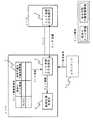
図1に示されるように本発明に係る第1の実施形態は、ネットワークを構成する各ノード内に、共有可能予備帯域を管理するリンク情報管理表1と、シェアードレストレーションで共有可能な予備帯域または予備パスの情報を広告するリンク情報広告処理部2と、他ノードから受け取った共有可能共有可能予備帯域及び共有可能予備パスを経路計算条件に加え、必要な予備帯域が最小となるような予備パスの経路を計算する経路計算処理部3と、を有する。
【0027】
ノードは、リンク情報管理表1で従来のリンク情報と共に共有可能な予備帯域情報を管理する。また、共有可能予備パスは、すべての帯域が共有可能予備帯域であるような論理的なリンクとして管理される。
【0028】
共有可能予備帯域及び共有可能予備パス情報には、その予備パスが保護している現用パスが属するSRG情報が含まれている。リンク情報広告処理部2は、リンク情報管理表1から、共有可能予備帯域および共有可能予備パス情報を含む自ノードのリンク情報を取得し、隣接するノードに送信する。また、リンク情報広告部2は、他のノードから受信したリンク情報を経路計算処理部3に渡す。
【0029】
受信したパス設定要求の障害回復タイプがシェアードレストレーションである場合、経路計算処理部3では、未予約帯域の情報に加え、予備パスに対してはすべての共有可能予備帯域が使用可能であるという条件のもとで最短かつ新規に予約が必要な帯域がもっとも少なくなるように現用パスと予備パスの経路を計算する。
【0030】
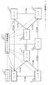
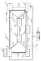
次に、図2に示されたネットワーク構成におけるパスの設定手順を説明する。パスが設定されていない状態で、ノードはSRG毎に共有可能予備帯域を管理している。初期状態でのリンク情報を図3に示す。各リンクのコストはすべて1であるとする。なお、リンクのコストとは、パスを設定する際に選択する通信回線を判断する尺度となるものであり、通信回線の通信速度や管理者のポリシーによって設定された値である。
【0031】
初めに、クライアント71がノード11に対して、ノード11からノード1までの障害回復タイプがシェアードレストレーションである10Mbpsのパス設定を要求する。この時のディスジョイントの基準は、SRGであるとする。このパスを以下ではパス101と呼ぶ。
【0032】
ノード11は、まず最短の経路を計算する。この場合、図2に示された、
{ノード11−リンク21−ノード12−リンク28−ノード17}
が該当する。このパス101が属するSRGは、{SRG91、SRG98}である。
【0033】
その後、この現用パスとSRGディスジョイントな予備パスを計算する。予備パスの経路としては、
{ノード11−リンク22−ノード13−リンク27−ノード14−リンク26−ノード17}
が計算される。経路の計算が終了すると、従来技術と同様にパス設定が行われる。パス101を設定後のリンク情報を図4に示す。図4に示されるように、パス101の予備パスに設定されたリンク22、リンク26、リンク27のSRG毎のシェアードレストレーション用共有可能予備帯域は、パス101のSRGに対しては「0」で、それ以外のSRGに対しては「10Mbps」と登録される。
【0034】
パス設定が完了すると、予約帯域に変化のあったリンクを管理するノードは、更新されたリンク情報を広告する。ノード11はリンク22のリンク情報を、従来のリンク情報だけでなくSRG毎に共有可能な予備帯域情報もつけて広告する。同様に、ノード14はリンク27のリンク情報を、ノード17はリンク26のリンク情報を同様に広告する。
【0035】
次に、クライアント71がノード11に対して、ノード11からノード16を経由してノード17まで障害回復タイプがシェアードレストレーションである10Mbpsのパス設定を要求する。このパスをパス102とする。ノード11はクライアント71のパス要求を満たす最短パスとして、
{ノード11−リンク29−ノード15−リンク24−ノード16−リンク25−ノード17}
を計算し、これをパス102の現用パスとする。この現用パスのSRGは{SRG99、SRG94、SRG95}である。
【0036】
その後、この現用パス102とSRGディスジョイントな予備パスを計算する。予備パスの候補として、
{ノード11−リンク21−ノード12−リンク28−ノード17}
{ノード11−リンク22−ノード13−リンク27−ノード14−リンク26−ノード17}
{ノード11−リンク21−ノード12−リンク23−ノード14−リンク26−ノード17}
{ノード11−リンク22−ノード13−リンク27−ノード14−リンク23−ノード12−リンク28−ノード17}
が挙げられる。
【0037】
ここでノード11は、各経路について新たに消費する未予約帯域を計算する。そして、これらの経路のなかでもっとも未予約帯域を消費しない経路を最適予備経路として選択する。この場合、
{ノード11−リンク22−ノード13−リンク27−ノード14−リンク26−ノード17}
の経路は、すべてのリンクにおいてパス101の予備帯域を共有することができ、未予約帯域を消費することがないため、予備経路としてこれが選択される。パス102設定後のリンク状態を図5に、パスの状況を図6に示す。パス102設定後のリンク状態は、図5に示されるように、パス101、及び102の予備パスに設定されたリンク22、26、27のSRG毎のシェアードレストレーション用共有可能予備帯域は、パス101とパス102のSRGに対しては「0」で、それ以外のSRGに対しては「10Mbps」と登録される。
【0038】
そして、従来同様パス設定が完了すると、予約帯域に変化のあったリンクを管理するノードは、更新されたリンク情報を広告する。ノード11はリンク22のリンク情報を、従来のリンク情報だけでなくSRG毎に共有可能な予備帯域情報もつけて広告する。同様に、ノード14はリンク27のリンク情報を、ノード17はリンク26のリンク情報を同様に広告する。
【0039】
このように本実施形態は、ネットワーク内の各リンクの共有可能予備帯域情報を、SRG毎に管理し、ネットワーク内の全ノードまたはNMS201に広告することにより、シェアードレストレーションにおける障害回復用の予備帯域を最小限に抑え、ネットワーク帯域を効率的に利用することが可能となる。
【0040】
[第2の実施形態]
次に、添付図面を参照しながら本発明に係る第2の実施形態について説明する。本発明に係る第2の実施形態は、パス101を設定するところまでは、上述した第1の実施形態と同様であるため説明を省略する。
【0041】
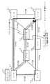
パス101を設定後、ノード11とノード17は、パス101の予備パスを論理的なリンクとして、SRG毎の共有可能予約帯域を従来のリンク情報と共に広告する。この論理的なリンクをリンク81とする。図7にパス101を設定後のネットワーク構成を、図8にリンク状態を示す。リンク81の未予約帯域は「0」で、SRG毎の共有可能予備帯域は、パス101のSRG(SRG ID[91]と[98])に対しては「0」、それ以外のSRG(SRG ID[90],[92],[93].[94],[95],[96],[97],[99])に対しては「10Mbps」で広告される。また、パス101の予備パスの経路にあるノード13とノード14は、未予約帯域の変化のみを広告する。すなわち、ノード13は、リンク21とリンク27の未予約帯域が「90Mbps」であることを広告し、ノード14は、リンク26とリンク27の未予約帯域が「90Mbps」であることを広告する。
【0042】
次に、上述した第1の実施形態と同様に、クライアント71からパス102のパス設定要求がきたとする。ノード11はクライアント71のパス要求を満たす最短パスとして、
{ノード11−リンク29−ノード15−リンク24−ノード16−リンク25−ノード17}
を計算し、これをパス102の現用パスとする。この現用パスのSRGは{SRG99、SRG94、SRG95}である。
【0043】
その後、この現用パスと重ならない予備パスを計算する。予備パスとしては、
{ノード11−リンク81−ノード17}
{ノード11−リンク21−ノード12−リンク28−ノード17}
{ノード11−リンク22−ノード13−リンク27−ノード14−リンク26−ノード17}
{ノード11−リンク21−ノード12−リンク23−ノード14−リンク26−ノード17}
{ノード11−リンク22−ノード13−リンク27−ノード14−リンク23−ノード12−リンク28−ノード17}
が候補として挙げられる。ここでノード11は、各経路について新たに消費する未予約帯域を計算する。そして、これらの経路のなかでもっとも未予約帯域を消費しない経路を最適予備経路として選択する。この場合、
{ノード11−リンク81−ノード17}
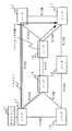
の経路は、すべてのリンクにおいてパス101の予備帯域を共有することができ、未予約帯域を消費することがないため、予備経路としてこれが選択される。パス102設定後のリンク状態を図9に、パスの状況を図10に示す。
【0044】
パス102を設定後、ノード11とノード17は、パス101とパス102の予備パスを論理的なリンクとして、SRG毎の共有可能予約帯域を従来のリンク情報と共に広告する。すなわち、ノード11とノード17は、リンク81の未予約帯域は「0」で、SRG毎の共有可能予備帯域は、パス101とパス102のSRG(SRG ID[91],[94],[95],[98],[99])に対しては「0」、それ以外のSRG(SRG ID[90],[92],[93],[96],[97])に対しては「10Mbps」で広告する。また、パス102の経路上にあるノード15は、リンク29とリンク24の未予約帯域の変化を、ノード16は、リンク24とリンク25の未予約帯域の変化を広告する。
【0045】
本実施形態も上述した第1の実施形態と同様に、シェアードレストレーションにおける障害回復用の予備帯域を最小限に抑え、ネットワーク帯域を効率的に利用することが可能となる。
【0046】
[第3の実施形態]
次に、添付図面を参照しながら本発明に係る第3の実施形態について説明する。本発明に係る第3の実施形態は、パス101を設定するところまでは、上述ひた第1の実施形態と同様であるため、その説明を省略する。
【0047】
パス設定が完了すると、予約帯域に変化のあったリンクを管理するノードは、更新されたリンク情報を広告する。ノード11はリンク22のリンク情報を、従来のリンク情報だけでなくSRG毎の共有可能予備帯域の最大値情報をつけて広告する。すなわち、共有可能予備帯域の中で、帯域幅が最大のSRGの帯域幅情報を広告する。この場合、リンク22のSRG毎の共有可能予備帯域は、図4に示されるようにSRG ID[92],[93],[94],[95],[96],[97],[99]で10Mbpsであるので、この10Mbpsという最大値情報を広告することになる。なお、ノード14、ノード17に関しても同様に共有可能予備帯域の中で、帯域幅が最大のSRGの帯域幅情報を従来のリンク情報と共に広告する。
【0048】
次に、パス102のパス設定要求がきた場合も、上述した第1の実施形態と同様に経路を計算する。ただし、異なる点は共有可能予備帯域は広告された最大値で使用可能であるという条件で予備パスを計算することである。
【0049】
現用パスのSRGによっては、使用可能な共有可能予備帯域はノード11が知っている最大共有可能予備帯域よりも小さい可能性がある。そうしたリンクを予備パスの経路として使用した場合はシグナリングまたはプロビジョニング時にパス設定が失敗し、再度経路計算をやり直すことになる。
【0050】
しかし、SRGの数は非常に多くなることが考えられ、広告するリンク情報量もそれに比例して大きくなる。共有可能帯域の最大値のみを広告することにより、広告する情報量を抑えることが可能となる。
【0051】
なお、上述した実施形態は、本発明の好適な実施の形態である。但し、これに限定されるものではなく、本発明の要旨を逸脱しない範囲内において種々変形実施が可能である。例えば、上述した実施形態においては、図1に示されたリンク情報管理表1、リンク情報広告処理部2、経路計算処理部3をノードに設けていたが、ネットワーク管理装置201にこれら各部を設け、ネットワーク管理装置がリンク情報を基に経路計算を行うものであってもよい。
【0052】
【発明の効果】
以上の説明より明らかなように本発明は、シェアードレストレーションにおける障害回復用予備帯域を最小限に抑え、ネットワーク帯域を効率的に利用することが可能となる。
【図面の簡単な説明】
【図1】本発明に係る実施形態の構成を表すブロック図である。
【図2】ネットワーク構成を表す図である。
【図3】リンク情報表の構成を表す図である。
【図4】リンク情報表の構成を表す図である。
【図5】リンク情報表の構成を表す図である。
【図6】パス設定状態を表す図である。
【図7】論理リンク広告後のネットワーク構成を表す図である。
【図8】リンク情報表の構成を表す図である。
【図9】リンク情報表の構成を表す図である。
【図10】論理リンクを使ったパス設定状態を表す図である。
【符号の説明】
1 リンク情報管理表
2 リンク情報広告処理部
3 経路計算処理部[0001]
BACKGROUND OF THE INVENTION
The present invention relates to a failure recovery method (hereinafter referred to as a shared rest) in which a plurality of working paths can share a protection path (hereinafter referred to as a protection path) or a protection band when communication becomes impossible due to a failure of the path. The present invention relates to a route control method and a route control apparatus that are optimal for use in a network that supports a network.
[0002]
[Prior art]
The network includes a client, a communication device (hereinafter referred to as a node), a network management device (hereinafter referred to as an NMS), and a communication line (hereinafter referred to as a link) connecting them. A connection of communication lines that can communicate between any two nodes or between two clients is called a path. Each node manages a reservation state of bandwidth information regarding a link to be connected.
[0003]
In addition, the setting of all nodes in the path by the NMS is called provisioning, and the path setting is performed in order from the start node to the end node (or vice versa) using a network protocol such as RSVP (Resource Reservation Protocol). This is called signaling. In provisioning or signaling, a node performs link bandwidth reservation or switch setting for a path. RSVP is defined in “RFC3209 RSVP-TE: Extensions to RSVP Tunnels”.
[0004]
The path setting request is made from the client or NMS to the node. The path setting request includes failure recovery type information for the path. Failure recovery type information includes shared restoration, 1 + 1 protection (a method that extends two paths and simultaneously sends signals to two paths), 1: 1 protection (a method that reserves an occupied spare band), unprotected, etc. There is.
[0005]
A node that receives a path setting request from a client or the like determines a method for calculating a protection path by looking at failure recovery type information included in the path setting request. There are two types of path route calculation: a case where a node receiving a path setting request performs, and a case where an NMS calculates and includes path information in a path setting request. The node or NMS uses only a link that can reserve the necessary bandwidth specified in the path setting request, and selects the path that minimizes the sum of the link costs from the start node to the end node of the path. Calculate the path of. Various link costs can be assigned depending on the communication speed and administrator policy. Information such as network topology information and link free bandwidth required for path route calculation may be advertised using a protocol such as OSPF (Open Shortest Path First routing), or a node may notify the NMS. In a method of advertising using a protocol such as OSPF, a node acquires link information of its own node and transmits it to an adjacent node. In addition, link information received from an adjacent node is transferred to another adjacent node. When the link information managed by the own node is changed, the changed link information is re-advertised. For the procedure of this advertisement, the internet draft "draft-katz-yeung-ospf-traffic-06" (hereinafter referred to as reference 1) and "draft-ietf-ccamp-ospf-gmpls-extensions-01" (hereinafter referred to as reference 2) Is shown in According to
[0006]
The shared restoration method is disclosed in the internet draft “draft-li-shared-mesh-restoration-01” (hereinafter referred to as Document 3). In shared restoration, when a backup path is set for a certain path for recovery from a failure, the bandwidth reserved for the backup path can be shared with a backup path of another path. Each node and link belongs to an SRG (Share Risk Group: a group that may go down simultaneously due to one failure) set by the administrator. Paths that do not belong to overlapping SRGs can be determined to be able to share a backup band without having to switch to the same backup path when a failure occurs because communication does not become impossible due to a single failure. . In the path calculation of the working path and the backup path, paths that do not overlap nodes, links, SRGs, etc. are calculated. Such paths are called disjoint. It is possible to specify in the path setting request what the reference path is to be disjoint. For example, when the SRG is used as a reference, the working path and the backup path are SGR disjoint.
[0007]
[Problems to be solved by the invention]
However, the conventional technology cannot advertise a spare band or a spare path that can be shared by shared restoration. For this reason, it has been impossible to calculate the path of the backup path that minimizes the required backup band by using the shareable backup band or the backup path.
[0008]
The present invention has been made in view of the above circumstances, and advertises information on a backup band or a backup path that can be shared by shared restoration, and calculates the route of the backup path using the information, thereby minimizing the backup path. It is an object of the present invention to provide a path control method and a path control apparatus that perform path control capable of recovering a failure in a band.
[0009]
[Means for Solving the Problems]
In order to achieve the object, the invention according to
[0010]
The invention according to
[0011]
According to a third aspect of the present invention, there is provided a routing control method in a network that supports a failure recovery method in which a plurality of working paths can share a protection band or a protection path for failure recovery, and each communication in the network Manages sharable bandwidth information for lines, manages backup paths reserved for failure recovery as logical communication lines, and sets backup paths reserved for failure recovery as logical communication lines. Advertising to all communication devices within the network or to a network management device that manages the communication devices.
[0012]
According to a fourth aspect of the present invention, there is provided a routing control method in a network that supports a failure recovery method in which a plurality of working paths can share a recovery band or a recovery path for failure recovery, and each communication in the network Line shareable backup bandwidth information is managed for each risk sharing group that may go down at the same time, and the backup path reserved for failure recovery is managed as a logical communication line and secured for failure recovery. The protection path is advertised as a logical communication line to all communication apparatuses in the network or a network management apparatus that manages the communication apparatus together with sharable protection band information for each risk sharing group.
[0013]
The invention according to
[0014]
According to a sixth aspect of the present invention, in the first or second aspect of the present invention, the communication device or network management device that has received the path setting request has a fault in a minimum bandwidth with the sharable spare bandwidth of each communication line as a constraint. It is characterized by calculating a route of a backup path that can be recovered.
[0015]
The invention according to
[0016]
The invention according to
[0017]
The invention according to
[0018]
The invention according to
[0019]
The invention according to claim 11 is a path control device that controls a path in a network that supports a fault recovery method in which a plurality of working paths can share a backup band or a backup path for fault recovery, Manages sharable backup bandwidth information for each communication line in the network, and reserves sharable backup bandwidth information management means that manages the backup path reserved for failure recovery as a logical communication line, and secures it for failure recovery. Link information advertising means for advertising the reserved path as a logical communication line to all communication devices in the network or to a network management device that manages the communication device.
[0020]
The invention according to claim 12 is a path control device that controls a path in a network that supports a fault recovery method in which a plurality of working paths can share a backup band or a backup path for fault recovery, Shared sharable bandwidth information for each communication line in the network is managed for each risk sharing group that may be down at the same time, and the protection path reserved for failure recovery is managed as a logical communication line Possible spare bandwidth information management means and a backup path reserved for failure recovery as a logical communication line together with shareable spare bandwidth information for each dangerous sharing group or all communication devices in the network or a network for managing the communication devices Link information advertising means for advertising to the management device.
[0021]
The invention according to claim 13 is a path control device that controls a path in a network that supports a fault recovery method in which a plurality of working paths can share a backup band or a backup path for fault recovery, A sharable spare bandwidth information management means for managing each sharable spare bandwidth information of each communication line in the network for each risk sharing group that may be down at the same time, and the highest bandwidth among the sharable spare bandwidths Link information advertising means for advertising the bandwidth information of the risk sharing group to all communication devices in the network or to a network management device that manages the communication devices.
[0022]
According to a fourteenth aspect of the present invention, in the invention according to the ninth or tenth aspect, the communication device or the network management device that has received the path setting request has a fault in a minimum bandwidth with the sharable spare bandwidth of each communication line as a constraint. It is characterized by having a route calculation means for calculating a route of a backup path that can be recovered.
[0023]
According to a fifteenth aspect of the invention, in the invention of the eleventh or twelfth aspect, the communication device or network management device that has received the path setting request considers the backup path of another working path as a logical link having a sharable spare bandwidth. And having a route calculation means for calculating a route of a backup path capable of performing failure recovery with a minimum bandwidth.
[0024]
According to a sixteenth aspect of the invention, in the thirteenth aspect of the invention, the communication device or network management device that has received the path setting request can use the shareable spare bandwidth notified by the bandwidth information. It is characterized by having a route calculation means for calculating a route of a backup path capable of performing failure recovery with a minimum bandwidth under conditions.
[0025]
DETAILED DESCRIPTION OF THE INVENTION
Next, embodiments of the route control method and the route control device of the present invention will be described in detail with reference to the accompanying drawings. 1 to 10 show an embodiment according to a route control method and a route control device of the present invention.
[0026]
[First Embodiment]
As shown in FIG. 1, in the first embodiment according to the present invention, a link information management table 1 for managing a sharable spare band and a spare band sharable by shared restoration are provided in each node constituting the network. Alternatively, the link information
[0027]
The node manages the spare bandwidth information that can be shared with the conventional link information in the link information management table 1. Further, the sharable backup path is managed as a logical link in which all bands are sharable backup bands.
[0028]
The sharable protection band and the sharable protection path information include SRG information to which the working path protected by the protection path belongs. The link information
[0029]
When the failure recovery type of the received path setting request is shared restoration, the route
[0030]
Next, a path setting procedure in the network configuration shown in FIG. 2 will be described. In a state where no path is set, the node manages a sharable spare band for each SRG. The link information in the initial state is shown in FIG. Assume that the cost of each link is all one. The link cost is a measure for determining a communication line to be selected when setting a path, and is a value set according to the communication speed of the communication line or the administrator's policy.
[0031]
First, the client 71 requests the node 11 to set a path of 10 Mbps with the failure recovery type from the node 11 to the
[0032]
The node 11 first calculates the shortest route. In this case, as shown in FIG.
{Node 11-Link 21-Node 12-Link 28-Node 17}
Is applicable. The SRG to which this path 101 belongs is {SRG91, SRG98}.
[0033]
Thereafter, the working path and the SRG disjoint backup path are calculated. As a route of the backup path,
{Node 11-Link 22-Node 13-Link 27-Node 14-Link 26-Node 17}
Is calculated. When the calculation of the route is completed, the path setting is performed as in the prior art. The link information after setting the path 101 is shown in FIG. As shown in FIG. 4, the shared restoration sharable spare band for each SRG of the link 22, link 26, and link 27 set as the backup path of the path 101 is “0” for the SRG of the path 101. Thus, “10 Mbps” is registered for other SRGs.
[0034]
When the path setting is completed, the node managing the link whose reserved bandwidth has changed advertises the updated link information. The node 11 advertises the link information of the link 22 with not only conventional link information but also spare band information that can be shared for each SRG. Similarly, the node 14 advertises the link information of the
[0035]
Next, the client 71 requests the node 11 to set a path of 10 Mbps whose failure recovery type is shared restoration from the node 11 to the node 17 via the node 16. This path is defined as path 102. As the shortest path that satisfies the path request of the client 71, the node 11
{Node 11-Link 29-Node 15-Link 24-Node 16-Link 25-Node 17}
And this is made the working path of the path 102. The SRG of this working path is {SRG99, SRG94, SRG95}.
[0036]
After that, an active path 102 and an SRG disjoint backup path are calculated. As a candidate for a backup path,
{Node 11-Link 21-Node 12-Link 28-Node 17}
{Node 11-Link 22-Node 13-Link 27-Node 14-Link 26-Node 17}
{Node 11-Link 21-Node 12-Link 23-Node 14-Link 26-Node 17}
{Node 11-Link 22-Node 13-Link 27-Node 14-Link 23-Node 12-Link 28-Node 17}
Is mentioned.
[0037]
Here, the node 11 calculates the unreserved bandwidth to be newly consumed for each route. Then, a route that consumes the least unreserved bandwidth among these routes is selected as the optimum backup route. in this case,
{Node 11-Link 22-Node 13-Link 27-Node 14-Link 26-Node 17}
This route is selected as a spare route because it can share the spare bandwidth of the path 101 in all links and does not consume unreserved bandwidth. FIG. 5 shows the link status after setting the path 102, and FIG. 6 shows the status of the path. As shown in FIG. 5, the link state after setting the path 102 is the shareable spare band for shared restoration for each SRG of the
[0038]
When the path setting is completed as in the prior art, the node that manages the link whose reserved bandwidth has changed advertises the updated link information. The node 11 advertises the link information of the link 22 with not only conventional link information but also spare band information that can be shared for each SRG. Similarly, the node 14 advertises the link information of the
[0039]
As described above, according to the present embodiment, the sharable spare band information of each link in the network is managed for each SRG and advertised to all the nodes in the network or the
[0040]
[Second Embodiment]
Next, a second embodiment according to the present invention will be described with reference to the accompanying drawings. Since the second embodiment according to the present invention is the same as the first embodiment described above until the path 101 is set, the description thereof is omitted.
[0041]
After setting the path 101, the node 11 and the node 17 advertise the shareable reserved bandwidth for each SRG together with the conventional link information by using the backup path of the path 101 as a logical link. This logical link is referred to as a link 81. FIG. 7 shows the network configuration after setting the path 101, and FIG. 8 shows the link state. The unreserved bandwidth of the link 81 is “0”, and the sharable spare bandwidth for each SRG is “0” for the SRG of the path 101 (SRG ID [91] and [98]), and the other SRG (SRG ID [90], [92], [93]. [94], [95], [96], [97], [99]) are advertised at “10 Mbps”. Further, the nodes 13 and 14 on the backup path of the path 101 advertise only the change of the unreserved bandwidth. That is, the node 13 advertises that the unreserved bandwidth of the link 21 and the
[0042]
Next, it is assumed that a path setting request for the path 102 is received from the client 71 as in the first embodiment described above. As the shortest path that satisfies the path request of the client 71, the node 11
{Node 11-Link 29-Node 15-Link 24-Node 16-Link 25-Node 17}
And this is made the working path of the path 102. The SRG of this working path is {SRG99, SRG94, SRG95}.
[0043]
Thereafter, a backup path that does not overlap with the working path is calculated. As a backup path,
{Node 11-Link 81-Node 17}
{Node 11-Link 21-Node 12-Link 28-Node 17}
{Node 11-Link 22-Node 13-Link 27-Node 14-Link 26-Node 17}
{Node 11-Link 21-Node 12-Link 23-Node 14-Link 26-Node 17}
{Node 11-Link 22-Node 13-Link 27-Node 14-Link 23-Node 12-Link 28-Node 17}
Is a candidate. Here, the node 11 calculates the unreserved bandwidth to be newly consumed for each route. Then, a route that consumes the least unreserved bandwidth among these routes is selected as the optimum backup route. in this case,
{Node 11-Link 81-Node 17}
This route is selected as a spare route because it can share the spare bandwidth of the path 101 in all links and does not consume unreserved bandwidth. FIG. 9 shows the link status after setting the path 102, and FIG. 10 shows the status of the path.
[0044]
After setting the path 102, the node 11 and the node 17 advertise the shareable reserved bandwidth for each SRG together with the conventional link information by using the backup path of the path 101 and the path 102 as a logical link. That is, in the node 11 and the node 17, the unreserved bandwidth of the link 81 is “0”, and the sharable spare bandwidth for each SRG is the SRG of the path 101 and the path 102 (SRG ID [91], [94], [95 ] For [98], [98], [99]), and “0” for other SRGs (SRG ID [90], [92], [93], [96], [97]). Advertise at “10Mbps”. Further, the node 15 on the path 102 advertises the change in the unreserved bandwidth of the
[0045]
Similarly to the first embodiment described above, the present embodiment can minimize the spare band for failure recovery in shared restoration and efficiently use the network band.
[0046]
[Third Embodiment]
Next, a third embodiment according to the present invention will be described with reference to the accompanying drawings. Since the third embodiment according to the present invention is the same as the above-described first embodiment until the path 101 is set, the description thereof is omitted.
[0047]
When the path setting is completed, the node managing the link whose reserved bandwidth has changed advertises the updated link information. The node 11 advertises the link information of the link 22 with the maximum value information of the sharable spare band for each SRG as well as the conventional link information. That is, the bandwidth information of the SRG having the maximum bandwidth is advertised in the shareable spare bandwidth. In this case, as shown in FIG. 4, the sharable spare band for each SRG of the link 22 is SRG ID [92], [93], [94], [95], [96], [97], [99]. ], The maximum value information of 10 Mbps is advertised. Similarly, regarding the node 14 and the node 17, the bandwidth information of the SRG having the maximum bandwidth is advertised together with the conventional link information in the shareable spare band.
[0048]
Next, even when a path setting request for the path 102 is received, the path is calculated in the same manner as in the first embodiment. However, the difference is that the backup path is calculated on the condition that the shareable backup band can be used at the advertised maximum value.
[0049]
Depending on the SRG of the working path, the usable sharable spare band may be smaller than the maximum sharable spare band known by the node 11. When such a link is used as a route for a protection path, path setting fails at the time of signaling or provisioning, and route calculation is performed again.
[0050]
However, it is conceivable that the number of SRGs will be very large, and the amount of link information to be advertised will also increase proportionally. By advertising only the maximum sharable bandwidth, the amount of information to be advertised can be reduced.
[0051]
The above-described embodiment is a preferred embodiment of the present invention. However, the present invention is not limited to this, and various modifications can be made without departing from the scope of the present invention. For example, in the above-described embodiment, the link information management table 1, the link information
[0052]
【The invention's effect】
As is clear from the above description, the present invention makes it possible to minimize the standby band for failure recovery in the shared restoration and efficiently use the network band.
[Brief description of the drawings]
FIG. 1 is a block diagram showing a configuration of an embodiment according to the present invention.
FIG. 2 is a diagram illustrating a network configuration.
FIG. 3 is a diagram illustrating a configuration of a link information table.
FIG. 4 is a diagram illustrating a configuration of a link information table.
FIG. 5 is a diagram illustrating a configuration of a link information table.
FIG. 6 is a diagram illustrating a path setting state.
FIG. 7 is a diagram illustrating a network configuration after a logical link advertisement.
FIG. 8 is a diagram illustrating a configuration of a link information table.
FIG. 9 is a diagram illustrating a configuration of a link information table.
FIG. 10 is a diagram illustrating a path setting state using a logical link.
[Explanation of symbols]
1 link information management table
2 Link information advertisement processing department
3 Route calculation processing part
Claims (16)
Translated fromJapanese前記ネットワーク内の各通信回線の共有可能予備帯域情報を、前記ネットワーク内の全通信装置または該通信装置を管理するネットワーク管理装置に広告することを特徴とする経路制御方法。A path control method in a network that supports a disaster recovery method in which a plurality of working paths can share a recovery band or a recovery path for failure recovery,
A route control method characterized by advertising shareable spare band information of each communication line in the network to all communication devices in the network or a network management device that manages the communication devices.
前記ネットワーク内の各通信回線の共有可能予備帯域情報を、同時にダウンする可能性のある危険共有グループ毎に管理し、前記ネットワーク内の全通信装置または該通信装置を管理するネットワーク管理装置に広告することを特徴とする経路制御方法。A path control method in a network that supports a disaster recovery method in which a plurality of working paths can share a recovery band or a recovery path for failure recovery,
The shareable spare band information of each communication line in the network is managed for each risk sharing group that may be down at the same time, and advertised to all communication devices in the network or a network management device that manages the communication devices. A path control method characterized by the above.
前記ネットワーク内の各通信回線の共有可能予備帯域情報を管理すると共に、障害回復用に確保された予備パスを、論理的な通信回線として管理し、
障害回復用に確保された予備パスを、論理的な通信回線としてネットワーク内の全通信装置または該通信装置を管理するネットワーク管理装置に広告することを特徴とする経路制御方法。A path control method in a network that supports a disaster recovery method in which a plurality of working paths can share a recovery band or a recovery path for failure recovery,
Managing sharable backup bandwidth information of each communication line in the network, managing a backup path reserved for failure recovery as a logical communication line,
A path control method characterized in that a backup path secured for failure recovery is advertised as a logical communication line to all communication devices in a network or a network management device that manages the communication devices.
前記ネットワーク内の各通信回線の共有可能予備帯域情報を、同時にダウンする可能性のある危険共有グループ毎に管理すると共に、障害回復用に確保された予備パスを、論理的な通信回線として管理し、
障害回復用に確保された予備パスを、論理的な通信回線として前記危険共有グループ毎の共有可能予備帯域情報と共にネットワーク内の全通信装置または該通信装置を管理するネットワーク管理装置に広告することを特徴とする経路制御方法。A path control method in a network that supports a disaster recovery method in which a plurality of working paths can share a recovery band or a recovery path for failure recovery,
Manage sharable backup bandwidth information of each communication line in the network for each risk sharing group that may be down at the same time, and manage backup paths reserved for failure recovery as logical communication lines. ,
The backup path reserved for failure recovery is advertised as a logical communication line to all communication devices in the network or the network management device managing the communication device together with the sharable backup bandwidth information for each risk sharing group. A characteristic route control method.
前記ネットワーク内の各通信回線の共有可能予備帯域情報を、同時にダウンする可能性のある危険共有グループ毎に管理し、
共有可能予備帯域の中で、帯域幅が最大の危険共有グループの該帯域幅情報を、前記ネットワーク内の全通信装置または該通信装置を管理するネットワーク管理装置に広告することを特徴とする経路制御方法。A path control method in a network that supports a disaster recovery method in which a plurality of working paths can share a recovery band or a recovery path for failure recovery,
Manage sharable spare bandwidth information of each communication line in the network for each risk sharing group that may be down at the same time,
Route control characterized by advertising the bandwidth information of a dangerous sharing group having the largest bandwidth among shareable spare bands to all communication devices in the network or a network management device that manages the communication devices. Method.
前記ネットワーク内の各通信回線の共有可能予備帯域情報を管理する共有可能予備帯域情報管理手段と、
前記各通信回線の共有可能予備帯域情報を前記ネットワーク内の全通信装置または該通信装置を管理するネットワーク管理装置に広告するリンク情報広告手段と、を有することを特徴とする経路制御装置。A path control device that performs path control in a network that supports a fault recovery method in which a plurality of working paths can share a backup band or a backup path for fault recovery,
Sharable spare bandwidth information management means for managing sharable spare bandwidth information of each communication line in the network;
And a link information advertising means for advertising the shareable spare band information of each communication line to all communication devices in the network or a network management device that manages the communication devices.
前記ネットワーク内の各通信回線の共有可能予備帯域情報を、同時にダウンする可能性のある危険共有グループ毎に管理する共有可能予備帯域情報管理手段と、
前記各通信回線の、危険共有グループ毎の共有可能予備帯域情報を前記ネットワーク内の全通信装置またはネットワーク管理装置に広告するリンク情報広告手段と、を有することを特徴とする経路制御装置。A path control device that performs path control in a network that supports a fault recovery method in which a plurality of working paths can share a backup band or a backup path for fault recovery,
Sharable spare bandwidth information managing means for managing sharable spare bandwidth information of each communication line in the network for each risk sharing group that may be down at the same time;
A path control device comprising link information advertising means for advertising sharable spare band information for each dangerous communication group of each communication line to all communication devices or network management devices in the network.
前記ネットワーク内の各通信回線の共有可能予備帯域情報を管理すると共に、障害回復用に確保された予備パスを、論理的な通信回線として管理する共有可能予備帯域情報管理手段と、
障害回復用に確保された予備パスを、論理的な通信回線としてネットワーク内の全通信装置または該通信装置を管理するネットワーク管理装置に広告するリンク情報広告手段と、を有することを特徴とする経路制御装置。A path control device that performs path control in a network that supports a fault recovery method in which a plurality of working paths can share a backup band or a backup path for fault recovery,
Sharable backup bandwidth information managing means for managing sharable backup bandwidth information of each communication line in the network and managing a backup path reserved for failure recovery as a logical communication line;
A link information advertisement unit that advertises a backup path reserved for failure recovery to all communication devices in the network or a network management device that manages the communication device as a logical communication line. Control device.
前記ネットワーク内の各通信回線の共有可能予備帯域情報を、同時にダウンする可能性のある危険共有グループ毎に管理すると共に、障害回復用に確保された予備パスを、論理的な通信回線として管理する共有可能予備帯域情報管理手段と、
障害回復用に確保された予備パスを、論理的な通信回線として前記危険共有グループ毎の共有可能予備帯域情報と共にネットワーク内の全通信装置または該通信装置を管理するネットワーク管理装置に広告するリンク情報広告手段と、を有することを特徴とする経路制御装置。A path control device that performs path control in a network that supports a fault recovery method in which a plurality of working paths can share a backup band or a backup path for fault recovery,
Manage sharable backup bandwidth information of each communication line in the network for each risk sharing group that may be down at the same time, and manage backup paths reserved for failure recovery as logical communication lines Sharable spare bandwidth information management means,
Link information that advertises a backup path reserved for failure recovery as a logical communication line to all communication devices in the network or a network management device that manages the communication device together with sharable backup bandwidth information for each risk sharing group And a route control device.
前記ネットワーク内の各通信回線の共有可能予備帯域情報を、同時にダウンする可能性のある危険共有グループ毎に管理する共有可能予備帯域情報管理手段と、
共有可能予備帯域の中で、帯域幅が最大の危険共有グループの該帯域幅情報を、前記ネットワーク内の全通信装置または該通信装置を管理するネットワーク管理装置に広告するリンク情報広告手段と、を有することを特徴とする経路制御装置。A path control device that performs path control in a network that supports a fault recovery method in which a plurality of working paths can share a backup band or a backup path for fault recovery,
Sharable spare bandwidth information managing means for managing sharable spare bandwidth information of each communication line in the network for each risk sharing group that may be down at the same time;
Link information advertising means for advertising the bandwidth information of the risk sharing group having the largest bandwidth among the sharable spare bands to all communication devices in the network or a network management device managing the communication devices; A route control device comprising:
Priority Applications (3)
| Application Number | Priority Date | Filing Date | Title |
|---|---|---|---|
| JP2002069986AJP3855809B2 (en) | 2002-03-14 | 2002-03-14 | Route control method and route control device |
| US10/385,894US20030174644A1 (en) | 2002-03-14 | 2003-03-12 | Routing control method and routing control apparatus for the same |
| EP03005641AEP1345364A1 (en) | 2002-03-14 | 2003-03-12 | Routing control method and routing control apparatus for the same |
Applications Claiming Priority (1)
| Application Number | Priority Date | Filing Date | Title |
|---|---|---|---|
| JP2002069986AJP3855809B2 (en) | 2002-03-14 | 2002-03-14 | Route control method and route control device |
Publications (2)
| Publication Number | Publication Date |
|---|---|
| JP2003273904A JP2003273904A (en) | 2003-09-26 |
| JP3855809B2true JP3855809B2 (en) | 2006-12-13 |
Family
ID=27764531
Family Applications (1)
| Application Number | Title | Priority Date | Filing Date |
|---|---|---|---|
| JP2002069986AExpired - LifetimeJP3855809B2 (en) | 2002-03-14 | 2002-03-14 | Route control method and route control device |
Country Status (3)
| Country | Link |
|---|---|
| US (1) | US20030174644A1 (en) |
| EP (1) | EP1345364A1 (en) |
| JP (1) | JP3855809B2 (en) |
Families Citing this family (20)
| Publication number | Priority date | Publication date | Assignee | Title |
|---|---|---|---|---|
| US20050025058A1 (en)* | 2003-07-30 | 2005-02-03 | Siddheswar Chaudhuri | Method for stochastic selection of improved cost metric backup paths in shared-mesh protection networks |
| JP4213546B2 (en)* | 2003-09-09 | 2009-01-21 | 富士通株式会社 | Communication apparatus and communication method |
| WO2005101759A1 (en) | 2004-04-14 | 2005-10-27 | Nec Corporation | Method for setting link attribute, method for calculating route and system employing them |
| CA2562096A1 (en)* | 2004-05-03 | 2005-11-24 | Ams Research Corporation | Surgical implants and related methods |
| JP4920308B2 (en)* | 2006-05-24 | 2012-04-18 | 株式会社日立製作所 | Path setting method, node device, and monitoring control device |
| JP4680151B2 (en)* | 2006-08-24 | 2011-05-11 | 富士通株式会社 | Data transmission method and apparatus |
| JP4764790B2 (en)* | 2006-09-20 | 2011-09-07 | 富士通株式会社 | Signal relay device, node device, network system, link generation method, and link generation program |
| US8824277B2 (en)* | 2007-01-09 | 2014-09-02 | Orange | Method of routing a data packet via a router in a packet communications network supported by a transport network |
| JP5166373B2 (en) | 2009-08-14 | 2013-03-21 | 株式会社日立製作所 | Transport control server, transport control system, and backup path setting method |
| WO2011067901A1 (en)* | 2009-12-03 | 2011-06-09 | 日本電気株式会社 | Communication system |
| US8811212B2 (en)* | 2012-02-22 | 2014-08-19 | Telefonaktiebolaget L M Ericsson (Publ) | Controller placement for fast failover in the split architecture |
| US9385945B2 (en) | 2012-10-05 | 2016-07-05 | Cisco Technology, Inc. | Identifying, translating and filtering shared risk groups in communications networks |
| US9049233B2 (en) | 2012-10-05 | 2015-06-02 | Cisco Technology, Inc. | MPLS segment-routing |
| JP6146016B2 (en)* | 2013-01-23 | 2017-06-14 | 日本電気株式会社 | Network management device, communication device, communication system, network management method, and computer program |
| US9537718B2 (en) | 2013-03-15 | 2017-01-03 | Cisco Technology, Inc. | Segment routing over label distribution protocol |
| FI20135519A7 (en)* | 2013-05-15 | 2014-11-16 | Tellabs Oy | A network element of a software-defined network |
| JP6344005B2 (en)* | 2014-03-28 | 2018-06-20 | 日本電気株式会社 | Control device, communication system, communication method, and program |
| US20190245807A1 (en)* | 2016-07-21 | 2019-08-08 | Nec Corporation | Communication path setting apparatus, communication path setting method and communication path setting program |
| US10892983B2 (en)* | 2018-07-27 | 2021-01-12 | Cisco Technology, Inc. | Shared risk link group robustness within and across multi-layer control planes |
| US11140074B2 (en) | 2019-09-24 | 2021-10-05 | Cisco Technology, Inc. | Communicating packets across multi-domain networks using compact forwarding instructions |
Family Cites Families (7)
| Publication number | Priority date | Publication date | Assignee | Title |
|---|---|---|---|---|
| US5235599A (en)* | 1989-07-26 | 1993-08-10 | Nec Corporation | Self-healing network with distributed failure restoration capabilities |
| JP2985940B2 (en)* | 1996-11-08 | 1999-12-06 | 日本電気株式会社 | Failure recovery device |
| US7428212B2 (en)* | 1999-01-15 | 2008-09-23 | Cisco Technology, Inc. | Best effort technique for virtual path restoration |
| US6512611B1 (en)* | 1999-12-23 | 2003-01-28 | Nortel Networks Limited | Method of deactivating protection fiber resources in optical ring networks |
| AU2001281240A1 (en)* | 2000-08-10 | 2002-02-25 | University Of Pittsburgh | Apparatus and method for spare capacity allocation |
| US20030095500A1 (en)* | 2001-10-23 | 2003-05-22 | Sycamore Networks, Inc. | Methods for distributed shared mesh restoration for optical networks |
| US20030117950A1 (en)* | 2001-12-26 | 2003-06-26 | Huang Gail G | Link redial for mesh protection |
- 2002
- 2002-03-14JPJP2002069986Apatent/JP3855809B2/ennot_activeExpired - Lifetime
- 2003
- 2003-03-12EPEP03005641Apatent/EP1345364A1/ennot_activeWithdrawn
- 2003-03-12USUS10/385,894patent/US20030174644A1/ennot_activeAbandoned
Also Published As
| Publication number | Publication date |
|---|---|
| EP1345364A1 (en) | 2003-09-17 |
| JP2003273904A (en) | 2003-09-26 |
| US20030174644A1 (en) | 2003-09-18 |
Similar Documents
| Publication | Publication Date | Title |
|---|---|---|
| JP3855809B2 (en) | Route control method and route control device | |
| US10250459B2 (en) | Bandwidth on-demand services in multiple layer networks | |
| US8018952B1 (en) | Automatic LSP stitching with protocol signaling | |
| US8675493B2 (en) | Routing bandwidth guaranteed paths with local restoration in label switched networks | |
| US7500013B2 (en) | Calculation of link-detour paths in mesh networks | |
| US7058845B2 (en) | Communication connection bypass method capable of minimizing traffic loss when failure occurs | |
| JP4374307B2 (en) | Label switch path routing control method | |
| US20070268821A1 (en) | Rpr representation in ospf-te | |
| JP5771832B2 (en) | Transmission system, management computer, and logical path construction method | |
| CN101227313A (en) | A business path adjustment method, a communication system, and a routing calculation unit | |
| JP5163479B2 (en) | Path switching method | |
| JP4765980B2 (en) | Communication network system | |
| WO2008040253A1 (en) | A method for processing the resource information of the traffic engineering link | |
| US20090103533A1 (en) | Method, system and node apparatus for establishing identifier mapping relationship | |
| CN103416028B (en) | Systems and methods for advertising composite links in interior gateway protocol and/or interior gateway protocol-traffic engineering | |
| CN101981878B (en) | Distributed resource management system, distributed resource management method, and distributed resource management program | |
| JP5077000B2 (en) | User management system and method for reserving a network path | |
| US8111612B2 (en) | Link-based recovery with demand granularity in mesh networks | |
| US8762568B1 (en) | Method and apparatus for inter-zone restoration | |
| EP1589708A1 (en) | Vpn communication control device, communication control method in vpn, and virtual dedicated network management device | |
| Aslam et al. | NPP: A facility based computation framework for restoration routing using aggregate link usage information | |
| JP3780987B2 (en) | Route control method and apparatus, route control program, and storage medium storing route control program | |
| Hasan et al. | Development of FRR mechanism by adopting SDN notion | |
| US20030043427A1 (en) | Method of fast circuit recovery using local restoration | |
| JP2009188673A (en) | Transmission apparatus and path setting method |
Legal Events
| Date | Code | Title | Description |
|---|---|---|---|
| A621 | Written request for application examination | Free format text:JAPANESE INTERMEDIATE CODE: A621 Effective date:20050221 | |
| A977 | Report on retrieval | Free format text:JAPANESE INTERMEDIATE CODE: A971007 Effective date:20060817 | |
| TRDD | Decision of grant or rejection written | ||
| A01 | Written decision to grant a patent or to grant a registration (utility model) | Free format text:JAPANESE INTERMEDIATE CODE: A01 Effective date:20060822 | |
| A61 | First payment of annual fees (during grant procedure) | Free format text:JAPANESE INTERMEDIATE CODE: A61 Effective date:20060904 | |
| R150 | Certificate of patent or registration of utility model | Ref document number:3855809 Country of ref document:JP Free format text:JAPANESE INTERMEDIATE CODE: R150 Free format text:JAPANESE INTERMEDIATE CODE: R150 | |
| FPAY | Renewal fee payment (event date is renewal date of database) | Free format text:PAYMENT UNTIL: 20090922 Year of fee payment:3 | |
| FPAY | Renewal fee payment (event date is renewal date of database) | Free format text:PAYMENT UNTIL: 20100922 Year of fee payment:4 | |
| FPAY | Renewal fee payment (event date is renewal date of database) | Free format text:PAYMENT UNTIL: 20110922 Year of fee payment:5 | |
| FPAY | Renewal fee payment (event date is renewal date of database) | Free format text:PAYMENT UNTIL: 20120922 Year of fee payment:6 | |
| FPAY | Renewal fee payment (event date is renewal date of database) | Free format text:PAYMENT UNTIL: 20130922 Year of fee payment:7 | |
| EXPY | Cancellation because of completion of term |