JP3855600B2 - Sliding door device for vehicle - Google Patents
Sliding door device for vehicleDownload PDFInfo
- Publication number
- JP3855600B2 JP3855600B2JP2000158624AJP2000158624AJP3855600B2JP 3855600 B2JP3855600 B2JP 3855600B2JP 2000158624 AJP2000158624 AJP 2000158624AJP 2000158624 AJP2000158624 AJP 2000158624AJP 3855600 B2JP3855600 B2JP 3855600B2
- Authority
- JP
- Japan
- Prior art keywords
- guide rail
- vehicle
- door
- guide
- slide
- Prior art date
- Legal status (The legal status is an assumption and is not a legal conclusion. Google has not performed a legal analysis and makes no representation as to the accuracy of the status listed.)
- Expired - Fee Related
Links
Images


Classifications
- E—FIXED CONSTRUCTIONS
- E05—LOCKS; KEYS; WINDOW OR DOOR FITTINGS; SAFES
- E05F—DEVICES FOR MOVING WINGS INTO OPEN OR CLOSED POSITION; CHECKS FOR WINGS; WING FITTINGS NOT OTHERWISE PROVIDED FOR, CONCERNED WITH THE FUNCTIONING OF THE WING
- E05F15/00—Power-operated mechanisms for wings
- E05F15/60—Power-operated mechanisms for wings using electrical actuators
- E05F15/603—Power-operated mechanisms for wings using electrical actuators using rotary electromotors
- E05F15/632—Power-operated mechanisms for wings using electrical actuators using rotary electromotors for horizontally-sliding wings
- E05F15/643—Power-operated mechanisms for wings using electrical actuators using rotary electromotors for horizontally-sliding wings operated by flexible elongated pulling elements, e.g. belts, chains or cables
- E05F15/646—Power-operated mechanisms for wings using electrical actuators using rotary electromotors for horizontally-sliding wings operated by flexible elongated pulling elements, e.g. belts, chains or cables allowing or involving a secondary movement of the wing, e.g. rotational or transversal
- E—FIXED CONSTRUCTIONS
- E05—LOCKS; KEYS; WINDOW OR DOOR FITTINGS; SAFES
- E05Y—INDEXING SCHEME ASSOCIATED WITH SUBCLASSES E05D AND E05F, RELATING TO CONSTRUCTION ELEMENTS, ELECTRIC CONTROL, POWER SUPPLY, POWER SIGNAL OR TRANSMISSION, USER INTERFACES, MOUNTING OR COUPLING, DETAILS, ACCESSORIES, AUXILIARY OPERATIONS NOT OTHERWISE PROVIDED FOR, APPLICATION THEREOF
- E05Y2201/00—Constructional elements; Accessories therefor
- E05Y2201/40—Motors; Magnets; Springs; Weights; Accessories therefor
- E05Y2201/43—Motors
- E05Y2201/434—Electromotors; Details thereof
- E—FIXED CONSTRUCTIONS
- E05—LOCKS; KEYS; WINDOW OR DOOR FITTINGS; SAFES
- E05Y—INDEXING SCHEME ASSOCIATED WITH SUBCLASSES E05D AND E05F, RELATING TO CONSTRUCTION ELEMENTS, ELECTRIC CONTROL, POWER SUPPLY, POWER SIGNAL OR TRANSMISSION, USER INTERFACES, MOUNTING OR COUPLING, DETAILS, ACCESSORIES, AUXILIARY OPERATIONS NOT OTHERWISE PROVIDED FOR, APPLICATION THEREOF
- E05Y2600/00—Mounting or coupling arrangements for elements provided for in this subclass
- E05Y2600/40—Mounting location; Visibility of the elements
- E05Y2600/41—Concealed
- E—FIXED CONSTRUCTIONS
- E05—LOCKS; KEYS; WINDOW OR DOOR FITTINGS; SAFES
- E05Y—INDEXING SCHEME ASSOCIATED WITH SUBCLASSES E05D AND E05F, RELATING TO CONSTRUCTION ELEMENTS, ELECTRIC CONTROL, POWER SUPPLY, POWER SIGNAL OR TRANSMISSION, USER INTERFACES, MOUNTING OR COUPLING, DETAILS, ACCESSORIES, AUXILIARY OPERATIONS NOT OTHERWISE PROVIDED FOR, APPLICATION THEREOF
- E05Y2600/00—Mounting or coupling arrangements for elements provided for in this subclass
- E05Y2600/40—Mounting location; Visibility of the elements
- E05Y2600/46—Mounting location; Visibility of the elements in or on the wing
- E—FIXED CONSTRUCTIONS
- E05—LOCKS; KEYS; WINDOW OR DOOR FITTINGS; SAFES
- E05Y—INDEXING SCHEME ASSOCIATED WITH SUBCLASSES E05D AND E05F, RELATING TO CONSTRUCTION ELEMENTS, ELECTRIC CONTROL, POWER SUPPLY, POWER SIGNAL OR TRANSMISSION, USER INTERFACES, MOUNTING OR COUPLING, DETAILS, ACCESSORIES, AUXILIARY OPERATIONS NOT OTHERWISE PROVIDED FOR, APPLICATION THEREOF
- E05Y2900/00—Application of doors, windows, wings or fittings thereof
- E05Y2900/50—Application of doors, windows, wings or fittings thereof for vehicles
- E05Y2900/53—Type of wing
- E05Y2900/531—Doors
Landscapes
- Power-Operated Mechanisms For Wings (AREA)
- Closing And Opening Devices For Wings, And Checks For Wings (AREA)
Description
Translated fromJapanese【0001】
【発明の属する技術分野】
本発明は、車両ボデーに形成されたドア開口を開閉するスライドドアを備えた車両用スライドドア装置に関するものであり、詳しくは、ドア開口を開閉すべくスライドドアをスライド動作させるパワースライドユニットに関するものである。
【0002】
【従来の技術】
従来、この種の車両用スライドドア装置としては、特開平10−18708号公報に示されるものが知られている。
【0003】
これは、車両ボデーに車両前後方向に延びるセンターガイドレールを介してスライド自在に支持され車両ボデーに形成されたドア開口を開閉するスライドドアを備えたものである。そして、スライドドアをスライド動作させるパワースライドユニットは、車両ボデー内に配設され駆動源となるモータ及び出力ドラムを備えた駆動機構と、駆動機構の出力ドラムに巻回されセンターガイドレールの車両後方側の端からセンターガイドレールに案内されてセンターガイドレールの車両前方側の端に配置された案内プーリにより折り返されて配索されると共にスライドドアに連係された無端状のケーブルとを有して構成されていた。
【0004】
この従来装置においては、モータの駆動による出力ドラムの回転で出力ドラムからケーブルを巻き取り・送り出してケーブルをセンターガイドレールに沿って往復動させ、これにより、スライドドアをスライド動作させてドア開口を開閉していた。
【0005】
【発明が解決しようとする課題】
しかし、上記した従来装置であると、駆動機構が車両ボデー内に配設されているので、その配置スペースやケーブルを配索するための開口等、車両ボデー側に専用の構造を必要とし、結果、パワースライドユニットを搭載するにあったっては、車両ボデーの制約を大きく受けることになる。又、センターガイドレールの端に案内プーリを必要とするので、その分だけセンターガイドレールが長くなり、結果、パワースライドユニットの搭載は、車両室内方への張り出しを大きくして車両室内スペースを犠牲することになる。更に、ケーブルがセンターガイドレールに沿って往復動するので、パワースライドユニットを使用しない手動の場合は、スライドドアのスライド動作がケーブルの摺動抵抗により重くなる。
【0006】
故に、本発明は、上記した従来装置の欠点を解消することを、その技術的課題とするものである。
【0007】
【課題を解決するための手段】
上記技術的課題を解決するために本発明において講じた技術的手段は、車両ボデーに車両前後方向に延びるガイドレールを介してスライド自在に支持され前記車両ボデーに形成されたドア開口を開閉するスライドドアを備え、前記スライドドア内に配設され出力ドラムを備えた駆動機構と、該駆動機構の前記出力ドラムに巻回され一端が前記ガイドレールの一方端側に固定され且つ他端が前記ガイドレールの他方端側に固定されたケーブルとを有し、前記出力ドラムの回転により前記ケーブルの一端側を前記出力ドラムに巻き取り且つ他端側を前記出力ドラムから送り出して前記スライドドアを前記ガイドレールで案内してスライド動作させる車両用スライドドア装置であって、前記スライドドアに揺動自在に支持され且つ前記ガイドレールに摺動自在に案内された支持体と、該支持体の前記スライドドアに対する揺動中心軸上及び前記ガイドレールに対する摺動部位に配設され前記ケーブルをクロスさせて案内する対の案内プーリとを有することを特徴とした、ことである。
【0008】
この技術的手段によれば、駆動機構がスライドドア内に配設されるので、よって、パワースライドユニットの搭載においては、車両ボデーの制約を受けず、組み付けしやすく、搭載性を向上し得る。又、ケーブルは、ガイドレ−ルに対して往復動しないので、ケーブルを配索するにあたって、ガイドレールは、案内プーリを必要とせず、又、ケーブルによる摺動抵抗の増加もない。
【0009】
より好ましくは、前記ガイドレールは、前記ドア開口より車両後部側の前記車両ボデーの室外面に配置される、と良い。
【0010】
より好ましくは、前記スライドドアに揺動自在に支持され且つ前記ガイドレールに摺動自在に支持された支持体と、該支持体の前記スライドドアに対する揺動中心軸上及び前記ガイドレールに対する摺動部位に配設され前記ケーブルをクロスさせて案内する対の案内プーリとを有する、と良い。
【0011】
【発明の実施の形態】
図1及び図2に示されるように、スライドドア1は、車両の側部ボデー2に形成された矩形のドア開口21を開閉するものであって、車両前後方向(図1示左右方向)に延在するセンターガイドレール3及び上下一対のアッパ及びロアガイドレール41、42を介して側部ボデー2に車両前後方向にガイドレール3、41、42に沿ってスライド自在に支持されている。
【0012】
アッパガイドレール41は、ドア開口21の上縁に沿ってこの上縁近傍に配置されており、側部ボデー2に固定されている。ロアガイドレール42は、ドア開口21の下縁に沿ってこの下縁近傍に配置されており、側部ボデー2に固定されている。又、センターガイドレール3は、ドア開口21より車両側部側の側部ボデー2の室外面に固定されている。
【0013】
スライドドア1には、それぞれ、ガイドレール3、41、42に摺動自在に案内されるガイドローラユニット5が揺動自在に支持されており、スライドドア1は、それぞれのガイドローラユニット5がガイドレール3、41、42に対して摺動することでガイドレール3、41、42に案内されてドア開口21を開閉すべくスライド動作する。尚、ガイドレール3、41、42は、互いに平行で、その前端は、ドア開口21の閉時において、スライドア1が側部ボデー2の室外面と略面一となるようにスライドドア1を案内するために、車両室内方に向かって屈曲している。又、ドア開口21の開時において、スライドドア1は、ドア開口21より車両後部側の側部ボデー2の室外面上に配置される。
【0014】
図5に示されるように、センターガイドレール3は、側部ボデー2の室外面に形成された凹部22内に配置されている。このセンターガイドレール3は、室外面に接合される垂直壁31、垂直壁31の上端及び下端から互いに平行に車両室外方へ屈曲延在する上壁32及び下壁33及び上壁32の室外端から垂直壁31と平行に下方に屈曲延在するフランジ壁34を備えており、断面略コ字形状を呈している。
【0015】
図3ないし図5に示されるように、ガイドローラユニット5は、スライドドア1に固定されるブラケット11に車両上下方向(図5示上下方向)に延びるピン12により相対回転自在に支持されたベースプレート51を備えている。このベースプレート51には、ブラケット11に支持される対の脚部分51a、51b及び先端がセンターガイドレール3の断面内に位置する対の水平フランジ51c、51dが形成されている。対の脚部分51a、51bは、車両上下方向において所定の間隔を持って互いに平行であって、その先端がブラケット11間に位置しており、ピン21は、この対の脚部分51a、51bを相対回転自在に貫通して延び、その両端でブラケット11に固着されている。これにより、ベースプレート51は、ブブラケット11に相対回転自在に支持され、ガイドローラユニット5をスライドドア1に揺動自在に支持している。対の水平フランジ51c、51dは、車両前後方向において同一平面上で所定の間隔をもって配置されており、その先端は、センターガイドレール3の上壁32及び下壁33と平行にその間に延在している。この水平フランジ51c、51dの先端には、内外ローラ52、53が回転自在に支持されている。内外ローラ52、53は、センターガイドレール3のフランジ壁34及び垂直壁31に摺接している。又、ベースプレート51には、上下ローラ54が回転自在に支持されており、この上下ローラ54は、センターガイドレール3の下壁33と摺接している。これにより、ガイドローラユニット5は、センターガイドレール3に車両上下方向及び車両室内外方向においてガタなく摺動自在に案内される。尚、アッパ及びロアガイドレール41、42に摺動自在に案内されるガイドローラユニット5も同様な構成となっている。これにより、スライドドア1は、ガイドローラユニット5によってガイドレール3、41、42を介して側部ボデー2にスライド自在に支持され、ガイドローラユニット5が後述するパワースライドユニットによりガイドレール3、41、42に対して摺動することでスライド動作する。
【0016】
次に本発明の主要部であるスライドドア1をスライド動作させるパワースライドユニットについて図1ないし図5を参照して説明する。
【0017】
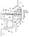
図2に示されるように、パワースライドユニットは、駆動機構6、ケーブル7、プーリ機構8を主として構成されている。
【0018】
駆動機構6は、スライドドア1内に配置されており、ブラケット等でスライドドア1のドアパネルに固定されている。この駆動機構6は、駆動源としてのモータ61及び回転自在な出力ドラム62からなる。出力ドラム62は、減速ギヤ構造63を介してモータ61の出力シャフトに連結されており、モータ61の正逆回転により一方向及び他方向に回転する。
【0019】
ケーブル7は、二本のワイヤ71、72からなり、ワイヤ71、72は、それぞれ、その一端で出力ドラム62に係止されて巻回されている。ワイヤ71の他端71aは、図3に示されるように、スライドドア1内のワイヤガイド9及びプーり機構8に案内されてセンターガイドレール3内に配索され、センターガイドレール3の車両前後方向における前端近傍の側部ボデー2のボデーパネルに係止されている。又、ワイヤ72の他端72aは、図4に示されるように、スライドドア1内の案内シュー9及びプーリ機構8に案内されてセンターガイドレール3内に配索され、センターガイドレール3の車両前後方向における後端の下壁33に係止されている。尚、ケーブル7は、二本のワイヤ71、72でなく、出力ドラム61に巻回されその両端がそれぞれ車両ボデー側の所定部位にそれぞれ係止された一本のワイヤより構成してもよい。又、ワイヤ71、72の他端71a、72aの係止は、スライドドア1のスライド範囲の車両前後方向における前端及び後端の車両ボデー側であれば前述した部位以外のどこでも良い。
【0020】
プーリ機構8は、ベースブラケット81によりガイドローラユニット5のベースプレート51にビス81aにて固定されている。ベースブラケット81には、対の案内プーリ82、83がピン82a、83aにより回転自在に支持されている。ピン82aは、ピン12と同軸上に位置し、案内プーリ82の回転中心軸は、ガイドローラユニット5の揺動中心軸と同軸となっている。又、案内プーリ83は、ローラ52、53間に配置されており、ワイヤ71、72を案内する外周の一部分がセンターガイドレール3内に位置している。ワイヤ71、72の他端71a、72aは、図3及び図4に示されるように、案内プーリ82、83の両側で案内されるようにクロスして案内プーリ82、83に案内され、センターガイドレール3内に配索されている。
【0021】
次に作動について説明する。
【0022】
ドア開口21の閉状態(スライドドア1が図2示実線に位置する状態)において、モータ61を正転駆動して出力ドラム62を一方向に回転させると、ケーブル7のワイヤ72が出力ドラム62に巻き取られ且つワイヤ71が出力ドラム62に巻き戻される(送り出される)。ワイヤ71、72は、その他端71a、72aにて車両ボデー側に固定されているので、案内プーリ83がセンターガイドレール3に沿ってガイドローラユニット5をセンターガイドレール3に対して摺動させながら車両後方(図2示右方)へ移動することになる。この結果、スライドドア1が開方向(図2示右方)へとスライド動作し、ドア開口21が開状態(スライドドア1が図2示二点鎖線に位置する状態)となる。
【0023】
ドア開口21の開状態において、モータ21を逆転駆動して出力ドラム62を他方向に回転させると、前述とは逆に、ケーブル7のワイヤ71が出力ドラム62かに巻き戻され(出力ドラム62から送り出され)且つワイヤ71が出力ドラム62に巻き取られる。これにより、案内プーリ83がセンターガイドレール3に沿ってガイドローラユニット5をセンターガイドレール3に対して摺動させながら車両前方(図2示左方)へ移動することになり、この結果、スライドドア1が閉方向(図2示左方)へとスライド動作し、ドア開口21が閉状態となる。
【0024】
スライドドア1のスライド動作によってドア開口21を閉状態から開状態とする際の開始直後及びドア開口21を開状態から閉状態とする終了直前において、ガイドローラユニット5は、ガイドレール3、41、42の前端の屈曲部分を摺動する。よって、ガイドローラユニット5は、ピン12を中心にスライドドア1に対して揺動してスライドドア1の姿勢を保つ。この際、ガイドローラユニット5の揺動は、ケーブル72のワイヤ71、72の巻き取り量と巻き戻し量を異ならせ、どちらか一方にゆるみを生じさせることになるが、ワイヤ71、72はクロスして対の案内プーリ82、83に案内されているので、ワイヤ71、72は、常に一定の量で巻き取り・巻き戻しされる。これにより、スライドドア1の滑らかなスライド動作を確保している。
【0025】
ケーブル7の案内プーリ82、83に対する配索は、案内プーリ82に対して片側のみで案内される図6に示される如き配索であっても良い。この場合、ワイヤ71、72のたるみを吸収するため他端71a、72aに張力調整機構を配すると良い。
【0026】
【発明の効果】
本発明によれば、駆動機構をスライドドア内に配設する共に駆動機構の出力ドラムに巻回したケーブルの両端をガイドレールに対して固定してパワースライドユニットを構成したので、パワースライドユニットの搭載においては、車両ボデーの制約を受けず、組み付けしやすく、搭載性を向上させることができる。
【0027】
又、本発明によれば、ケーブルをガイドレールに対して往復動させることなく、スライドドアをスライド動作させることができるので、ガイドレール側には、案内プーリが不要となり、車両室内スペースを犠牲にすることなく、パワースライドユニットを搭載できる。又、ケーブルによる摺動抵抗の増加も抑制でき、操作性を向上させることができる。
【図面の簡単な説明】
【図1】本発明に係る車両用スライドドア装置を搭載した車両の側面図である。
【図2】本発明に係る車両用スライドドア装置を搭載した車両の断面図である。
【図3】本発明に係る車両用スライドドア装置の閉状態時におけるパワースライドユニットの正面図である。
【図4】本発明に係る車両用スライドドア装置の開状態時におけるパワースライドユニットの正面図である。
【図5】図3の縦断面図である。
【図6】本発明に係る車両用スライドドア装置のケーブルの配索の変形例を示す図3に相当する正面図である。
【符号の説明】
1 スライドドア
2 側部ボデー(車両ボデー)
3 センターガイドレール(ガイドレール)
5 ガイドローラユニット(支持体)
6 駆動機構
7 ケーブル
21 ドア開口
62 出力ドラム
82、83 案内プーリ[0001]
BACKGROUND OF THE INVENTION
The present invention relates to a vehicle slide door device having a slide door that opens and closes a door opening formed in a vehicle body, and more particularly to a power slide unit that slides a slide door to open and close the door opening. It is.
[0002]
[Prior art]
Conventionally, as this type of vehicle sliding door device, one disclosed in Japanese Patent Laid-Open No. 10-18708 has been known.
[0003]
This includes a slide door that is slidably supported by a vehicle body via a center guide rail extending in the vehicle front-rear direction and opens and closes a door opening formed in the vehicle body. The power slide unit that slides the slide door includes a drive mechanism that is disposed in the vehicle body and includes a motor that serves as a drive source and an output drum, and a center guide rail that is wound around the output drum of the drive mechanism. An endless cable guided by a center guide rail from a side end and folded and routed by a guide pulley disposed at a front end of the center guide rail on the vehicle, and linked to a sliding door Was composed.
[0004]
In this conventional apparatus, the cable is wound and sent out from the output drum by the rotation of the output drum driven by the motor, and the cable is reciprocated along the center guide rail, whereby the sliding door is slid to open the door opening. It was opened and closed.
[0005]
[Problems to be solved by the invention]
However, in the case of the above-described conventional device, since the drive mechanism is disposed in the vehicle body, a dedicated structure is required on the vehicle body side, such as an arrangement space and an opening for routing the cable. When the power slide unit is mounted, the vehicle body is greatly restricted. In addition, since a guide pulley is required at the end of the center guide rail, the center guide rail becomes longer by that amount. As a result, the installation of the power slide unit increases the overhang to the vehicle interior and sacrifices the vehicle interior space. Will do. Further, since the cable reciprocates along the center guide rail, the sliding operation of the sliding door becomes heavier due to the sliding resistance of the cable in the case of manual operation not using the power slide unit.
[0006]
Therefore, this invention makes it the technical subject to eliminate the fault of the above-mentioned conventional apparatus.
[0007]
[Means for Solving the Problems]
In order to solve the above technical problem, the technical means taken in the present invention is a slide that is slidably supported on a vehicle body via a guide rail extending in the vehicle front-rear direction and opens and closes a door opening formed in the vehicle body. A drive mechanism including an output drum provided in the slide door, one end of which is wound around the output drum of the drive mechanism fixed to one end side of the guide rail, and the other end is the guide A cable fixed to the other end side of the rail, and by rotating the output drum, one end side of the cable is wound around the output drum and the other end side is sent out from the output drum to guide the slide door to the guide and guide raila slide door apparatus for a vehicle for slidingmovement, is swingably supported by the sliding door and the guide rail A support body slidably guided, and a pair of guide pulleys disposed on a swinging central axis of the support body with respect to the slide door and at a sliding portion with respect to the guide rail to guide the cable in a crossing manner. It is characterized byhaving .
[0008]
According to this technical means, the drive mechanism is disposed in the slide door. Therefore, the mounting of the power slide unit is not restricted by the vehicle body, can be easily assembled, and the mountability can be improved. In addition, since the cable does not reciprocate with respect to the guide rail, the guide rail does not require a guide pulley when the cable is routed, and the sliding resistance due to the cable does not increase.
[0009]
More preferably, the guide rail may be disposed on an exterior surface of the vehicle body on the vehicle rear side from the door opening.
[0010]
More preferably, a support body swingably supported by the slide door and slidably supported by the guide rail, and a slide of the support body on the swing center axis of the slide door and the guide rail. It is good to have a pair of guide pulleys arranged at the site and guiding the cable by crossing.
[0011]
DETAILED DESCRIPTION OF THE INVENTION
As shown in FIGS. 1 and 2, the sliding
[0012]
The
[0013]
A
[0014]
As shown in FIG. 5, the
[0015]
As shown in FIGS. 3 to 5, the
[0016]
Next, a power slide unit that slides the
[0017]
As shown in FIG. 2, the power slide unit mainly includes a drive mechanism 6, a
[0018]
The drive mechanism 6 is disposed in the
[0019]
The
[0020]
The
[0021]
Next, the operation will be described.
[0022]
When the
[0023]
When the
[0024]
Immediately after the start when the
[0025]
The
[0026]
【The invention's effect】
According to the present invention, the power slide unit is configured by arranging the drive mechanism in the slide door and fixing both ends of the cable wound around the output drum of the drive mechanism to the guide rail. In mounting, it is easy to assemble without being restricted by the vehicle body, and the mounting property can be improved.
[0027]
In addition, according to the present invention, the sliding door can be slid without reciprocating the cable with respect to the guide rail. Therefore, no guide pulley is required on the guide rail side, and the vehicle interior space is sacrificed. Power slide unit can be installed without doing so. Further, an increase in sliding resistance due to the cable can be suppressed, and operability can be improved.
[Brief description of the drawings]
FIG. 1 is a side view of a vehicle equipped with a vehicle sliding door device according to the present invention.
FIG. 2 is a cross-sectional view of a vehicle equipped with a vehicle sliding door device according to the present invention.
FIG. 3 is a front view of the power slide unit in a closed state of the vehicle slide door device according to the present invention.
FIG. 4 is a front view of the power slide unit when the vehicle slide door device according to the present invention is in an open state.
FIG. 5 is a longitudinal sectional view of FIG. 3;
6 is a front view corresponding to FIG. 3 and showing a modified example of cable routing of the vehicle sliding door device according to the present invention. FIG.
[Explanation of symbols]
1 Sliding
3 Center guide rail (guide rail)
5 Guide roller unit (support)
6 Drive
Claims (2)
Translated fromJapanesePriority Applications (3)
| Application Number | Priority Date | Filing Date | Title |
|---|---|---|---|
| JP2000158624AJP3855600B2 (en) | 2000-05-29 | 2000-05-29 | Sliding door device for vehicle |
| DE10125897ADE10125897C2 (en) | 2000-05-29 | 2001-05-28 | Opening and closing device for a vehicle sliding door |
| US09/865,727US6530619B2 (en) | 2000-05-29 | 2001-05-29 | Opening and closing device for sliding vehicle door |
Applications Claiming Priority (1)
| Application Number | Priority Date | Filing Date | Title |
|---|---|---|---|
| JP2000158624AJP3855600B2 (en) | 2000-05-29 | 2000-05-29 | Sliding door device for vehicle |
Publications (2)
| Publication Number | Publication Date |
|---|---|
| JP2001336352A JP2001336352A (en) | 2001-12-07 |
| JP3855600B2true JP3855600B2 (en) | 2006-12-13 |
Family
ID=18663066
Family Applications (1)
| Application Number | Title | Priority Date | Filing Date |
|---|---|---|---|
| JP2000158624AExpired - Fee RelatedJP3855600B2 (en) | 2000-05-29 | 2000-05-29 | Sliding door device for vehicle |
Country Status (3)
| Country | Link |
|---|---|
| US (1) | US6530619B2 (en) |
| JP (1) | JP3855600B2 (en) |
| DE (1) | DE10125897C2 (en) |
Families Citing this family (39)
| Publication number | Priority date | Publication date | Assignee | Title |
|---|---|---|---|---|
| AT410819B (en)* | 2000-08-31 | 2003-08-25 | Siemens Sgp Verkehrstech Gmbh | DOOR MOUNTING |
| US6481783B1 (en)* | 2001-04-25 | 2002-11-19 | Delphi Technologies, Inc. | Drive mechanism for power operated slideable side door |
| FR2826685B1 (en)* | 2001-06-27 | 2004-02-27 | Wagon Automotive Snc | DEVICE FOR DRIVING A MOTOR VEHICLE DOOR, CORRESPONDING DOOR, TROLLEY AND VEHICLE |
| JP4747471B2 (en)* | 2001-09-10 | 2011-08-17 | アイシン精機株式会社 | Sliding door device for vehicle |
| CA2468643C (en) | 2001-11-29 | 2010-11-23 | Intier Automotive Closures Inc. | Drive assembly for a power closure panel |
| JP3837081B2 (en) | 2002-03-29 | 2006-10-25 | 三井金属鉱業株式会社 | Power sliding device for vehicle sliding door |
| JP3726960B2 (en)* | 2002-06-20 | 2005-12-14 | 三井金属鉱業株式会社 | Power sliding device for vehicle sliding door |
| US6854212B2 (en)* | 2003-03-06 | 2005-02-15 | Arvinmeritor Technology, Llc. | Belt drive system for sliding vehicle door |
| US7243461B2 (en)* | 2003-03-19 | 2007-07-17 | Rogers Jr Lloyd W | Hinge mechanism for a sliding door |
| US6793268B1 (en) | 2003-05-12 | 2004-09-21 | Daimlerchrysler Corporation | Gliding door assembly for a motor vehicle |
| US7144068B2 (en)* | 2003-11-20 | 2006-12-05 | Intier Automotive Closures Inc. | Drive mechanism for selectively opening and closing a closure panel manually or automatically |
| US7159930B2 (en)* | 2004-03-31 | 2007-01-09 | Mitsui Mining & Smelting Co., Ltd. | Power slide device for vehicle sliding door |
| JP4153904B2 (en)* | 2004-06-24 | 2008-09-24 | 三井金属鉱業株式会社 | Roller arm unit for vehicle sliding door |
| US7481728B2 (en)* | 2004-06-29 | 2009-01-27 | Siemens Energy & Automation, Inc. | System and apparatus for driving a track mounted robot |
| DE102004062470A1 (en)* | 2004-12-20 | 2006-11-02 | Kabelschlepp Gmbh | Guidance system for an energy guidance unit and crane arrangement |
| WO2006086893A1 (en)* | 2005-02-18 | 2006-08-24 | Magna Closures Inc. | Power sliding door having a linear drive mechanism |
| WO2006086892A1 (en)* | 2005-02-18 | 2006-08-24 | Magna Closures Inc. | Compact cable drive power sliding door mechanism |
| US7393044B2 (en)* | 2005-05-31 | 2008-07-01 | Mitsuba Corporation | Vehicle door opening and closing structure |
| JP2006348668A (en)* | 2005-06-17 | 2006-12-28 | Mitsuba Corp | Sliding door opening and closing device |
| ATE457887T1 (en)* | 2005-08-11 | 2010-03-15 | Brose Schliesssysteme Gmbh | SLIDING DOOR |
| US7770961B2 (en)* | 2006-02-20 | 2010-08-10 | Magna Closures Inc. | Compact cable drive power sliding door mechanism |
| CA2604306A1 (en)* | 2006-09-25 | 2008-03-25 | Magna Closures Inc. | Belt-driven rack gear power sliding door |
| US8127497B2 (en)* | 2006-09-26 | 2012-03-06 | Strattec Power Access Llc | Apparatus and method for providing a sliding door mechanism |
| JP4750661B2 (en)* | 2006-09-28 | 2011-08-17 | 三井金属アクト株式会社 | Support structure for vehicle sliding door |
| JP5040512B2 (en)* | 2006-10-27 | 2012-10-03 | 日産自動車株式会社 | Car sliding door structure |
| WO2008106037A2 (en)* | 2007-02-28 | 2008-09-04 | Corning Incorporated | Photonic crystal fibers and methods for manufacturing the same |
| JP5125234B2 (en) | 2007-06-05 | 2013-01-23 | アイシン精機株式会社 | Sliding door device for vehicle |
| JP2009127290A (en)* | 2007-11-22 | 2009-06-11 | Aisin Seiki Co Ltd | Vehicle door opening and closing device |
| WO2009107722A1 (en)* | 2008-02-28 | 2009-09-03 | アイシン精機株式会社 | Vehicle door opening/closing device |
| US7856759B2 (en)* | 2008-12-18 | 2010-12-28 | Ford Global Technologies, Llc | Dual action power drive unit for a vehicle door |
| US8800205B2 (en)* | 2009-01-16 | 2014-08-12 | Aisin Seiki Kabushiki Kaisha | Door opening-and-closing apparatus for vehicle |
| JP5633141B2 (en)* | 2009-11-27 | 2014-12-03 | アイシン精機株式会社 | Vehicle door opening and closing device |
| KR20150074806A (en)* | 2013-12-24 | 2015-07-02 | 기아자동차주식회사 | Sliding door for vehicle |
| KR101542981B1 (en)* | 2013-12-27 | 2015-08-07 | 현대자동차 주식회사 | Front door device of vehicle |
| KR101542980B1 (en)* | 2013-12-27 | 2015-08-07 | 현대자동차 주식회사 | Rear door device of vehicle |
| US9238399B2 (en)* | 2014-04-11 | 2016-01-19 | Aisin Technical Center Or America, Inc. | Slide structure for power slide door and cable assembly method for slide door center |
| KR101637289B1 (en)* | 2014-11-06 | 2016-07-07 | 현대자동차 주식회사 | Sliding door device for vehicle |
| US10017978B2 (en)* | 2016-03-16 | 2018-07-10 | Honda Motor Co., Ltd. | Methods and apparatus for overriding powered vehicle door |
| CN109538073A (en)* | 2019-01-30 | 2019-03-29 | 张卫 | Shared push-and-pull car door |
Family Cites Families (10)
| Publication number | Priority date | Publication date | Assignee | Title |
|---|---|---|---|---|
| JPS6418708A (en)* | 1987-07-15 | 1989-01-23 | Yokohama Rubber Co Ltd | Pneumatic tire wheel |
| US5233789A (en)* | 1992-11-16 | 1993-08-10 | General Motors Corporation | Adjustable cable guide assembly for powered sliding vehicle door closer |
| US5316365A (en)* | 1993-01-25 | 1994-05-31 | General Motors Corporation | Sliding door closed loop cable closure system with balanced cable tension and varying diameter pulleys |
| US5319881A (en)* | 1993-01-25 | 1994-06-14 | General Motors Corporation | Sliding door closed loop cable closure system with balanced cable length and varying diameter pulleys |
| US5319880A (en)* | 1993-01-25 | 1994-06-14 | General Motors Corporation | Sliding door opening cable system with cable slack take-up |
| US5323570A (en)* | 1993-01-25 | 1994-06-28 | General Motors Corporation | Door opening cable system with cable slack take-up |
| US5531498A (en)* | 1994-12-01 | 1996-07-02 | Chrysler Corporation | Vehicle body with powered lift type tailgate |
| JPH1018708A (en) | 1996-07-03 | 1998-01-20 | Mitsuba Corp | Electric sliding door for vehicles |
| DE19819421C2 (en)* | 1998-04-30 | 2001-11-08 | Kiekert Ag | Sliding door drive for the sliding door of a motor vehicle |
| US6092338A (en)* | 1999-01-27 | 2000-07-25 | Hy-Security Gate, Inc. | Barrier operator system |
- 2000
- 2000-05-29JPJP2000158624Apatent/JP3855600B2/ennot_activeExpired - Fee Related
- 2001
- 2001-05-28DEDE10125897Apatent/DE10125897C2/ennot_activeExpired - Fee Related
- 2001-05-29USUS09/865,727patent/US6530619B2/ennot_activeExpired - Lifetime
Also Published As
| Publication number | Publication date |
|---|---|
| DE10125897A1 (en) | 2002-01-31 |
| US20020043818A1 (en) | 2002-04-18 |
| US6530619B2 (en) | 2003-03-11 |
| DE10125897C2 (en) | 2003-06-18 |
| JP2001336352A (en) | 2001-12-07 |
Similar Documents
| Publication | Publication Date | Title |
|---|---|---|
| JP3855600B2 (en) | Sliding door device for vehicle | |
| US7328934B2 (en) | Sliding door opening and closing device | |
| JP4447634B2 (en) | Automatic opening / closing device for vehicle sliding door | |
| JP4283561B2 (en) | Sliding door opening and closing device | |
| US20160333626A1 (en) | Vehicle door opening device | |
| JP2009102958A (en) | Swing slide door opening and closing device | |
| US20020007599A1 (en) | Vehicle closure member fabrication process facilitated by vehicle door glass regulator | |
| JP4747471B2 (en) | Sliding door device for vehicle | |
| US7533926B2 (en) | Roller arm unit for vehicle sliding door | |
| JP4404045B2 (en) | Auto swing sliding door system | |
| JP2007223402A (en) | Sliding door opening and closing device | |
| JP4099859B2 (en) | Sliding door device for vehicle | |
| JP4852811B2 (en) | Sliding door device for vehicle | |
| JP2007270426A (en) | Sliding door opening/closing device | |
| JP4972800B2 (en) | Automatic opening / closing device for vehicle sliding door | |
| JP3937066B2 (en) | Sliding door drive mechanism | |
| JP2004124446A (en) | Slide door device for vehicle | |
| JP3145221U (en) | Drive mechanism for electric curtain device | |
| JP3485045B2 (en) | Electric sliding door device for vehicles | |
| JP4747468B2 (en) | Sliding door device for vehicle | |
| JP2013132910A (en) | Vehicular rear lamp and vehicle body side part structure | |
| JPH09310555A (en) | Powder window device of car door | |
| JP4803870B2 (en) | Opening and closing device for vehicle opening and closing body | |
| JP3995675B2 (en) | Roller arm unit for vehicle sliding door | |
| JP3926194B2 (en) | Wire type window regulator |
Legal Events
| Date | Code | Title | Description |
|---|---|---|---|
| A621 | Written request for application examination | Free format text:JAPANESE INTERMEDIATE CODE: A621 Effective date:20050228 | |
| A977 | Report on retrieval | Free format text:JAPANESE INTERMEDIATE CODE: A971007 Effective date:20060523 | |
| A131 | Notification of reasons for refusal | Free format text:JAPANESE INTERMEDIATE CODE: A131 Effective date:20060530 | |
| A521 | Written amendment | Free format text:JAPANESE INTERMEDIATE CODE: A523 Effective date:20060727 | |
| TRDD | Decision of grant or rejection written | ||
| A01 | Written decision to grant a patent or to grant a registration (utility model) | Free format text:JAPANESE INTERMEDIATE CODE: A01 Effective date:20060822 | |
| A61 | First payment of annual fees (during grant procedure) | Free format text:JAPANESE INTERMEDIATE CODE: A61 Effective date:20060904 | |
| R151 | Written notification of patent or utility model registration | Ref document number:3855600 Country of ref document:JP Free format text:JAPANESE INTERMEDIATE CODE: R151 | |
| FPAY | Renewal fee payment (event date is renewal date of database) | Free format text:PAYMENT UNTIL: 20100922 Year of fee payment:4 | |
| FPAY | Renewal fee payment (event date is renewal date of database) | Free format text:PAYMENT UNTIL: 20110922 Year of fee payment:5 | |
| FPAY | Renewal fee payment (event date is renewal date of database) | Free format text:PAYMENT UNTIL: 20120922 Year of fee payment:6 | |
| FPAY | Renewal fee payment (event date is renewal date of database) | Free format text:PAYMENT UNTIL: 20130922 Year of fee payment:7 | |
| LAPS | Cancellation because of no payment of annual fees |