JP3855443B2 - Telephone equipment - Google Patents
Telephone equipmentDownload PDFInfo
- Publication number
- JP3855443B2 JP3855443B2JP7611798AJP7611798AJP3855443B2JP 3855443 B2JP3855443 B2JP 3855443B2JP 7611798 AJP7611798 AJP 7611798AJP 7611798 AJP7611798 AJP 7611798AJP 3855443 B2JP3855443 B2JP 3855443B2
- Authority
- JP
- Japan
- Prior art keywords
- telephone
- counterpart device
- telephone number
- history information
- time
- Prior art date
- Legal status (The legal status is an assumption and is not a legal conclusion. Google has not performed a legal analysis and makes no representation as to the accuracy of the status listed.)
- Expired - Fee Related
Links
Images


Landscapes
- Telephone Function (AREA)
- Meter Arrangements (AREA)
Description
Translated fromJapanese【0001】
【発明の属する技術分野】
本発明は電話装置に関し、特に、相手側装置との通信に関する履歴情報を表示することができる電話装置に関するものである。
【0002】
【従来の技術】
近年、電話はなくてはならないものであり、人々は電話を仕事や生活の上で多く活用している。電話での通話を行う場合、通常、通話者は、その通話相手との過去の通話内容に基づいて、今回の通話内容を決めている。例えば、仕事上の打ち合わせ等において、過去の通話内容を思い出すことにより、今回の通話を円滑に進めることができるのである。
【0003】
【発明が解決しようとする課題】
しかしながら、通話回数の多い相手や前回の通話から長時間が経過した相手の場合においては、その通話相手と何時、如何なる内容の通話をしたのか思い出すことは困難であるという問題点があった。
【0004】
本発明は上述した問題点を解決するためになされたものであり、相手側装置との通信に関する履歴情報を表示することができる電話装置を提供することを目的としている。
【0005】
【課題を解決するための手段】
この目的を達成するために請求項1記載の電話装置は、回線の閉結前に交換機側から送られる相手側装置の電話番号を受信可能な受信手段を備えており、更に、相手側装置の電話番号に対応つけて、その相手側装置との回線の閉結前または閉結時における通信に関する履歴情報を記憶する履歴記憶手段と、前記受信手段により受信された相手側装置の電話番号が前記履歴記憶手段に記憶される相手側装置の電話番号と一致するか否かを判断する判断手段と、その判断手段により相手側装置の電話番号が一致すると判断された場合に、前記相手側装置の電話番号に対応つけて前記履歴記憶手段に記憶される履歴情報として相手側装置との前回の回線閉結後の着呼日時の履歴または着呼回数を表示する表示手段とを備えている。
【0006】
この請求項1記載の電話装置によれば、交換機側から送られる相手側装置の電話番号が受信手段により受信されると、判断手段によって、その受信された相手側装置の電話番号が履歴記憶手段に記憶される相手側装置の電話番号と一致するか否か判断される。判断の結果、両電話番号が一致する場合には、表示手段によって、その相手側装置の電話番号に対応つけて履歴記憶手段に記憶される履歴情報としての相手側装置との前回の回線閉結後の着呼日時の履歴または着呼回数が表示される。
【0007】
請求項2記載の電話装置は、発呼先である相手側装置の電話番号を記憶する発呼先記憶手段を備えており、更に、相手側装置の電話番号に対応つけて、その相手側装置との回線の閉結前または閉結時における通信に関する履歴情報を記憶する履歴記憶手段と、前記発呼先記憶手段に記憶される相手側装置の電話番号が前記履歴記憶手段に記憶される相手側装置の電話番号と一致するか否かを判断する判断手段と、その判断手段により相手側装置の電話番号が一致すると判断された場合に、前記相手側装置の電話番号に対応つけて前記履歴記憶手段に記憶される履歴情報を表示する表示手段とを備えている。
【0008】
この請求項2記載の電話装置によれば、発呼先記憶手段により発呼先である相手側装置の電話番号が記憶されると、判断手段によって、その記憶される相手側装置の電話番号が履歴記憶手段に記憶される相手側装置の電話番号と一致するか否か判断される。判断の結果、両電話番号が一致する場合には、表示手段によって、その相手側装置の電話番号に対応つけて履歴記憶手段に記憶される回線の閉結前または閉結時における通信に関する履歴情報が表示される。
【0009】
請求項3記載の電話装置は、請求項1または2に記載の電話装置において、前記表示手段は、履歴情報として相手側装置との回線の閉結日時の履歴または回線の閉結回数を表示するものである。
【0010】
請求項4記載の電話装置は、請求項2又は3に記載の電話装置において、前記表示手段は、履歴情報として相手側装置との前回の回線閉結後の着呼日時の履歴または着呼回数を表示するものである。
【0011】
請求項5記載の電話装置は、請求項1から4のいずれかに記載の電話装置において、相手側装置との通信に関するコメントを入力するコメント入力手段を備え、前記表示手段は、そのコメント入力手段により入力されたコメントを履歴情報として表示するものである。
【0012】
請求項6記載の電話装置は、請求項1から5のいずれかに記載の電話装置において、文字や記号を記録媒体上に印刷する印刷手段を備え、前記印刷手段は、履歴情報を記録媒体上に印刷するものである。
【0013】
【発明の実施の形態】
以下、本発明の好ましい実施例について、添付図面を参照して説明する。図1は、本発明の一実施例であるファクシミリ装置1の外観斜視図である。ファクシミリ装置1の本体2の側部には、受話器3が取り付けられている。受話器3は非通話時には本体2に設けられた図示しないフック上に置かれ、通話時にはフックから取り上げられて使用される。前者をオンフック状態、後者をオフフック状態と称している。
【0014】
本体2の上面前部には複数のボタン4aを備えた操作パネル4が設けられ、その操作パネル4の左上端部には、相手側装置からの着信(着呼(呼出信号の着信)に応答して電話回線を閉結すること)があった日時と、その着信した全着信回数と、その着信時におけるコメント(通話内容等)とをLCD5へ表示するための着信情報ボタン4bが設けられている。また、着信情報ボタン4bの下には、相手側装置との電話回線の閉結前または閉結時における通信に関する履歴情報をプリンタ25により記録紙Pへ印刷するための印刷ボタン4cが設けられている。操作パネル4の左後部には、2行表示することが可能な液晶表示器(LCD)5が設けられている。ファクシミリ装置1は、この操作パネル4上に設けられた各ボタン4aが押下されることにより操作されるとともに、その操作状態や操作手順などがLCD5へ表示される。
【0015】
操作パネル4及びLCD5の後部には原稿挿入口6が設けられている。ファクシミリ送信される原稿は、この原稿挿入口6に原稿面を下向きにして挿入され、読み取りが行われた後に、本体2の前面であって操作パネル4の下方に設けられた原稿排出口7から排出される。原稿挿入口6の後部には記録紙ホルダ装着部9が設けられており、この記録紙ホルダ装着部9には、複数枚の記録紙Pを積層収納可能な記録紙ホルダ10が着脱可能に取り付けられている。記録紙ホルダ10から供給され、プリンタ25により印刷に使用された記録紙Pは、原稿排出口7の下方に設けられた記録紙排出口8から排出される。また、本体2の側面部にはスピーカ28が設けられており、着呼(呼出信号の着信)した相手側装置に対応する名称(氏名)は、このスピーカ28から音声出力される。
【0016】
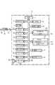
図2は、本ファクシミリ装置1の電気的構成を示したブロック図である。ファクシミリ装置1には、CPU11、ROM12、EEPROM13、RAM14、画像メモリ15、音声メモリ16、音声LSI17、ネットワーク・コントロール・ユニット(以下「NCU」と称す)19、モデム20、バッファ21、スキャナ22、符号化部23、復号化部24、プリンタ25、操作パネル4、アンプ27、スピーカ28及び時計回路33が備えられ、これらはバスライン30を介して互いに接続されている。
【0017】
NCU19は回線制御を行うためのものであり、ファクシミリ装置1はこのNCU19を介して電話回線31に接続されている。NCU19は、交換機29から送信される呼出信号や相手側装置(発信者)の電話番号(発信者番号)等を受信すると共に、操作パネル4上に設けられているボタン4aの操作に応じた発信時のダイヤル信号を交換機29へ送信したり、更には通話時におけるアナログ音声信号の送受信を行うものである。
【0018】
CPU11は、NCU19を介して送受信される各種信号に従って、バスライン30により接続された各部を制御してファクシミリ動作や電話動作、即ち、データ通信を実行するものである。時計回路33は時刻の計時を行うためのものであり、時計回路33により計時された時刻はCPU11によって読み出され、各処理に使用される。ROM12は、このファクシミリ装置1で実行される制御プログラムなどを格納した書換不能なメモリであり、図7から図12までのフローチャートに示すプログラムは、このROM12内に格納されている。
【0019】
EEPROM13は、書換可能な不揮発性のメモリであり、相手側装置メモリ13aを備えている。この相手側装置メモリ13aは、予め、相手側装置の電話番号と、その相手側装置の電話番号に対応する名称(氏名)と、その相手側装置との電話回線の閉結前または閉結時における通信に関する履歴情報とを互いに対応つけて記憶するメモリである。図3に、その相手側装置メモリ13aの構成を模式的に示す。なお、履歴情報は、相手側装置からの着信(着呼に応答して電話回線を閉結すること)日時と、その着信に対して通話者が入力したコメント(通話内容等)と、その着信した全着信回数と、相手側装置との前回の着信後からの着呼(呼出信号の着信)日時と、その着呼した着呼回数とによって構成されている。
【0020】
図3に示すように、相手側装置メモリ13aには、電話番号エリア13bと、名称エリア13cと、着信日時エリア13dと、コメントエリア13eと、着信回数カウンタ13fと、着呼日時エリア13gと、着呼回数カウンタ13hとが設けられている。電話番号エリア13bは、相手側装置の電話番号を記憶するためのエリアであり、名称エリア13cは、その相手側装置の電話番号に対応つけて、相手側装置の名称を記憶するためのエリアである。名称エリア13cの内容は、相手側装置からの着呼があった場合に、その着呼した相手側装置の電話番号に対応つけて記憶されているものが、LCD5へ表示されるとともに、スピーカ28から音声出力される。よって、受信者は、着呼のあった相手側装置を確実に認識することができるのである。
【0021】
着信日時エリア13dは、相手側装置からの着信があった場合、着信した日時をその相手側装置の電話番号に対応つけて各相手側装置ごとに記憶するためのエリアであり、過去半年分の着信日時が記憶可能となっている。コメントエリア13eは、その着信日時エリア13dのデータに対応するコメントを記憶するためのエリアである。このコメントエリア13eには、コメントとして、例えば「伊豆での旅行について」のように、通話者により入力された通話内容の要点などが記憶される。着信回数カウンタ13fは、過去半年分の全着信回数を着信のあった各相手側装置ごとに記憶するためのカウンタである。なお、本実施例においては、着信日時エリア13dの内容とコメントエリア13eの内容と着信回数カウンタ13fの値とを記憶する期間は過去半年間とされているが、操作者による操作パネル4上のボタン4aの押下操作によって、かかる記憶期間を変更できるようにしても良い。
【0022】
着呼日時エリア13gは、前回の着信後からの着呼した日時を各相手側装置ごとに記憶するためのエリアである。また、着呼回数カウンタ13hは、前回の着信後からの着呼した回数を各相手側装置ごとに記憶するためのカウンタである。なお、着呼日時エリア13gのデータ及び着呼回数カウンタ13hの値は、前回の着信後からの着呼に対して記憶され、次の着信があると、その着信のあった相手側装置の着呼日時エリア13gのデータ及び着呼回数カウンタ13hの値は、ともにクリアされる。
【0023】
図4に示すように、相手側装置からの着呼があると、LCD5の上の行に、発信者の名称(氏名)101が、下の行に、前回の着呼(呼出)日時102及び着呼(呼出)回数103が、それぞれ表示される。よって、受信者は、その相手側装置による着呼日時や着呼回数を把握した上で、電話回線を閉結したり或いは電話回線の閉結を拒否したりすることができるのである。また、受信者は、不在等の理由によって閉結することができなかった電話の回数を着信前(通話前)に認識することができるので、例えば、その回数を通話相手に伝えるとともに閉結できなかったことを謝まって通話相手の不快感を解消することができるのである。
【0024】
操作パネル4の着信情報ボタン4bが、着信時に受信者によって押下されると、図5に示すように、LCD5の上の行に、前回の着信(通話)日時111及び全着信(全通話)回数112が、下の行に、前回の着信時におけるコメント(通話内容等)113が、それぞれ表示される。よって、受信者は、単にLCD5の表示内容を見るだけで、相手側装置との着信日時と着信回数を把握することができるとともに、コメント113によって前回の着信時における通話内容を詳細に把握することができる。従って、例えば、仕事上の打ち合わせ等においても、受信者は、把握したこれらの通信履歴(着信日時,全着信回数,通話内容)に基づいて通話を行うことができるので、円滑に通話を進めることができるのである。
【0025】
また、印刷ボタン4cが、着信時に受信者によって押下されると、図6に示すように、全ての履歴情報121〜127がプリンタ25により記録紙Pに印刷される。LCD5の表示では、着呼日時102、着信日時111、及び、着信時におけるコメント113では最新の履歴情報しか表示されないので、受信者が最新の履歴情報以外の過去の履歴情報を見ることのできるように考慮したものである。具体的な印刷内容としては、受信した相手側装置の電話番号121、その受信した相手側装置の名称122、その相手側装置との前回の着信後からの着呼(呼出)回数123、その着呼日時124、かかる相手側装置との前回までの全着信(全通話)回数125、その着信日時126、その着信時におけるコメント127という順番で印刷される。
【0026】
なお、着信日時126とその着信時におけるコメント127とは互いに対応付けされて、着信日時126の横にコメント127が印刷される。また、着呼日時124と着信日時126は、それぞれ新しい日時(情報)から順番に印刷され、各着信日時126の横に印刷されるコメント127としては、受信者により操作パネル4を介して入力されたコメントである「伊豆での旅行について」や「近況報告(長男誕生)」等の着信内容の要点が印刷されるのである。
【0027】
このようにプリンタ25によって履歴情報を記録紙P上へ印刷することにより、受信者は、履歴情報が印刷された記録紙Pを手元に置いて通話を行うことができ、その記録紙Pの表示内容を見ることによって通話を円滑に進めることができるのである。また、履歴情報が多量にある場合でも、その履歴情報を記録紙P上に印刷することにより、履歴情報を複数枚の記録紙Pに分けて印刷することができる。よって、表示内容の限られたLCD5に履歴情報を表示する場合に比べて、受信者は、相手側装置との通信履歴を容易に把握することができるのである。
【0028】
図2におけるRAM14は、ファクシミリ装置1の各動作の実行時に各種のデータを一時的に記憶するためのメモリであり、発信者番号メモリ14aと記憶フラグ14bとを備えている。
【0029】
発信者番号メモリ14aは、電話回線の閉結前に着呼(呼出信号の着信)があった際に、いわゆる発信電話番号表示サービスによって交換機29から送信される相手側装置(発信者)の電話番号(発信者番号)を一時的に記憶するためのメモリである。ここで「発信電話番号表示サービス」とは、被呼側装置が当該サービスに加入している場合に、交換機29から被呼側装置へ、電話回線を閉結する前に相手側装置の電話番号を送信するサービスである。このサービスを利用すれば、被呼側装置は、相手側装置の電話番号を電話回線の閉結前に受信することができるのである。このため、着呼があっても交換機29から相手側装置の電話番号が送信されない場合には、発信者番号メモリ14aの内容を「0」クリアしている。よって、発信者番号メモリ14aの内容が「0」でなければ、発信者番号メモリ14aに記憶される電話番号の相手側装置からの着呼であると判断でき、一方、発信者番号メモリ14aの内容が「0」であれば、着呼のあった相手側装置の電話番号が交換機29から送信されなかったと判断することができる。
【0030】
なお、電話回線の閉結前または閉結時における通信中の相手側装置としては、本ファクシミリ装置1への発呼側装置のみでなく、本ファクシミリ装置1からの発呼先装置を通信中の相手側装置として用いることも当然に可能である。この場合には、本ファクシミリ装置1によって発呼された発呼先の電話番号を発信者番号メモリ14aへ記憶する。
【0031】
記憶フラグ14bは、相手側装置からの着呼があり、その相手側装置の電話番号を受信することができた場合に、その受信した電話番号が前記した電話番号メモリ13aに記憶されているか否かを示すフラグである。受信した相手側装置の電話番号が電話番号メモリ13aに記憶されていれば、記憶フラグ14bはオンされ、一方、記憶されていなければ、記憶フラグ14bはオフされる。
【0032】
画像メモリ15は、通信履歴、画像データ及び印刷のためのビットイメージを記憶するためのメモリであり、安価な大容量メモリであるダイナミックRAM(DRAM)により構成されている。受信された画像データは、一旦画像メモリ15に記憶され、プリンタ25によって記録紙Pに印刷された後に、この画像メモリ15から消去される。一般に、画像データは大容量であるが、画像データが印刷されることを条件にその画像データを消去しているので、画像メモリ15を有効に使用することができる。音声メモリ16は、相手側装置(発呼側装置)へ送出される応答メッセージや、相手側装置から送られてきた入来メッセージを記憶するメモリである。画像メモリ15と同様に、安価な大容量メモリであるダイナミックRAM(DRAM)により構成されている。音声メモリ16に記憶された入来メッセージは、操作パネル4を介して消去操作がなされることにより、或いは、電話回線に接続された他の装置から送られる消去コマンドを受信することによって、消去される。
【0033】
音声LSI17は、NCU19によって受信されたアナログ音声信号をデジタル音声信号に変換する音声認識処理を行うとともに、このファクシミリ装置1の内部で生成されたデジタル音声信号をアナログ音声信号に変換して、NCU19やスピーカ28(アンプ27)へ出力する音声合成処理を行うためのものである。前記したように、着呼した相手側装置の電話番号が電話番号メモリ13aに記憶されている場合には、この音声LSI17による音声合成処理によって、名称エリア13cの内容がアナログ音声信号に変換され、アンプ27を介して、スピーカ28から音声出力される。
【0034】
モデム20は、画情報を変調及び復調して伝送すると共に伝送制御用の各種手順信号を送受信するためのものであり、バッファ21は、相手側ファクシミリ装置との間で送受信される符号化された画情報を含むデータを一時的に格納するためのものである。スキャナ22は、原稿挿入口6に挿入された原稿から画像を読み取るためのものであり、符号化部23は、スキャナ22により読み取られた画像の符号化を行うものである。復号化部24は、バッファ21又は画像メモリ15に記憶された受信画像データを読み出して、これを復号化するものであり、復号化されたデータは、プリンタ25により記録紙Pに印刷される。
【0035】
操作パネル4は、操作者がこのファクシミリ装置1の設定等を行う場合に各種の操作を行うためのものであり、アンプ27は、そのアンプ27に接続されたスピーカ28を鳴動して、呼出音や音声を出力するためのものである。
【0036】
このように構成されたファクシミリ装置1は、NCU19を介して、電話回線31に接続されている。この電話回線31は、本ファクシミリ装置1の交換機29に接続され、この交換機29は電話回線32を介して、他の交換機に接続されている。なお、他の交換機は、更に、電話回線を介して相手側装置や転送先となる他の装置に接続されている。
【0037】
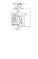
次に、図7から図12のフローチャートを参照して、上記のように構成されたファクシミリ装置1の動作について説明する。図7は、着信時における処理を示したフローチャートである。図7に示すように、ファクシミリ装置1は呼出信号を待機し(S1:No)、呼出信号があると(S1:Yes)、図8に示す着呼情報表示処理を実行する(S2)。
【0038】
図8に示す着呼情報表示処理では、まず、前記した発信電話番号表示サービスにより交換機側から送られる相手側装置の電話番号(発信者番号)を受信したか否かを確認する(S20)。本ファクシミリ装置1が発信電話番号表示サービスに加入していても、発信者が電話番号の送信を拒否している場合には、交換機29から発信者番号は送信されないので、発信者番号を受信することができない。よって、かかる場合には(S20:No)、発信者番号メモリ14aの内容を「0」クリアして(S21)、発信者番号が受信できなかったことを記憶する。その後、記憶フラグ14bをオフするとともに(S22)、呼出音を鳴動して(S23)、この着呼情報表示処理を終了する。
【0039】
一方、発信者番号を受信した場合には(S20:Yes)、その受信した発信者番号をRAM14の発信者番号メモリ14aへ書き込み(S24)、受信した発信者番号がEEPROM13の電話番号エリア13bに記憶されているか否かを判断する(S25)。なお、このような処理は、ファクシミリ装置1からの発呼にともなう電話回線の閉結前または閉結時おいても適用可能であり、かかる場合、その発呼による相手側装置の電話番号をRAM14の発信者番号メモリ14aへ書き込み(S24)、発呼した相手側装置の電話番号がEEPROM13の電話番号エリア13bに記憶されているか否かを判断する(S25)。そして、S25の判断の結果、電話番号エリア13bに記憶されていなければ(S25:No)、発信者番号メモリ14aの内容をLCD5の上の行へ表示し(S26)、記憶フラグ14bをオフするとともに(S22)、呼出音を鳴動して(S23)、この着呼情報表示処理を終了する。
【0040】
S25の処理において、受信した発信者番号が電話番号エリア13bに記憶されていれば(S25:Yes)、その発信者番号に対応する名称エリア13cの内容、即ち、その発信者番号に対応して記憶される相手側装置の名称をLCD5の上の行へ表示するとともに(S27,図4の101)、名称エリア13cの内容(相手側装置の名称)をスピーカ28から音声出力する(S28)。よって、受信者は、着呼のあった相手側装置を確実に認識することができるのである。
【0041】
音声出力後(S28)、受信した発信者番号に対応する着呼日時エリア13gの最新の内容、即ち、その発信者番号に対応する相手側装置との前回の着呼日時をLCD5の下の行へ表示するとともに(S29,図4の102)、受信した発信者番号に対応する着呼回数カウンタ13hの値、即ち、かかる相手側装置との前回の着信後(電話回線の閉結後)からの着呼回数をもLCD5の下の行へ表示する(S30,図4の103)。表示後、記憶フラグ14bをオンして(S31)、受信した発信者番号が電話番号エリア13bに記憶されていることを記憶し、この着呼情報表示処理を終了する。
【0042】
このように着呼情報表示処理では、相手側装置からの着呼があり、その相手側装置の電話番号(発信者番号)が電話番号メモリ13aに記憶されている場合には、相手側装置との前回の着呼日時102と前回の着信後からの着呼回数103とがLCD5へ表示される。よって、受信者は、その相手側装置との着呼日時や着呼回数を把握した上で、電話回線を閉結したり、或いは、頻繁にかかるいたずら電話の場合には電話回線の閉結を拒否したりすることができるのである。
【0043】
着呼情報表示処理(S2)を終了すると、処理を図7のS3へ移行して、呼出信号が継続しているか否かを確認する(S3)。呼出信号が継続していれば(S3:Yes)、受話器3が取り上げられたか否か、即ち、オフフック状態であるか否かを確認する(S4)。オンフック状態であれば(S4:No)、処理をS2へ移行して、呼出信号が継続する間(S3:Yes)、S2からS4の処理を繰り返す。また、その間に呼出信号が中断すれば(S3:No)、図9に示す第1更新処理を実行する(S5)。
【0044】
図9に示す第1更新処理では、まず、記憶フラグ14bの内容がオンであるか否かを確認する(S41)。記憶フラグ14b内容がオフであれば(S41:No)、即ち、発信者番号を受信することができなかったか、または、発信者番号を受信してもその受信した発信者番号が電話番号エリア13bに記憶されていない場合には、相手側装置メモリ13aに記憶された履歴情報を更新する必要がないので、そのまま、この第1更新処理を終了する。一方、記憶フラグ14bの内容がオンであれば(S41:Yes)、受信した発信者番号に対応する着呼回数カウンタ13hの値を1加算するとともに(S42)、受信した発信者番号に対応する着呼日時エリア13gの内容へ新たに着呼のあった日時を付加して(S43)、着呼に関する履歴情報を更新する。履歴情報の更新後、この第1更新処理を終了する。
【0045】
第1更新処理の終了後、処理を図7のS15へ移行して、LCD5の表示を消去する(S15)。その後、処理をS1へ移行して、次の呼出信号を待機するのである(S1)。
【0046】
S4の処理において、受話器3が取り上げられて、オフフック状態となれば(S4:Yes)、電話回線を閉結するとともに(S6)、電話処理を実行する(S7)。電話処理の実行中に、受信者によって着信情報ボタン4bが押下されたか否かを判断し(S8)、判断の結果、着信情報ボタン4bが押下されれば(S8:Yes)、図10に示す着信情報表示処理を実行する(S9)。
【0047】
図10の着信情報表示処理では、まず、記憶フラグ14bの内容がオンであるか否かを確認する(S51)。記憶フラグ14bの内容がオンでなければ(S51:No)、即ち、発信者番号を受信することができなかったか、または、発信者番号を受信してもその受信した発信者番号が電話番号エリア13bに記憶されていない場合には、相手側装置メモリ13aの履歴情報を表示(検索)することができないので、そのまま、この着信情報表示処理を終了する。
【0048】
一方、記憶フラグ14bの内容がオンであれば(S51:Yes)、受信した発信者番号に対応する着信日時エリア13dの最新の内容、即ち、その発信者番号に対応する相手側装置からの前回の着信日時と、着信回数カウンタ13fの値、即ち、相手側装置との過去半年分の全着信回数とを、LCD5の上の行へ表示する(S52,図5の111,S53,図5の112)。その後、受信した発信者番号に対応するコメントエリア13eの内容、即ち、かかる相手側装置との前回の着信時におけるコメントをLCD5の下の行へ表示して(S54,図5の113)、この着信情報表示処理を終了する。
【0049】
このように着信情報表示処理では、相手側装置からの着信があり、受信者によって着信情報ボタン4bが押下された場合に、相手側装置からの前回の着信日時111と、その相手側装置との過去半年分の全着信回数112と、前回の着信時におけるコメント113とがLCD5へ表示される。よって、受信者は、単にLCD5の表示内容を見るだけで、相手側装置との前回の着信日時と全着信回数とを把握することができるとともに、コメントによって前回の通話内容を詳細に把握することができるのである。
【0050】
着信情報表示処理(S9)を終了後、または、図7のS8の処理において受信者により着信情報ボタン4bが押下されない場合には(S8:No)、処理を図7のS10へ移行して、受信者により印刷ボタン4cが押下されたか否かを判断する(S10)。判断の結果、印刷ボタン4cが押下されていれば(S10:Yes)、図11に示すプリンタ出力処理を実行する(S11)。
【0051】
図11に示すプリンタ出力処理では、まず、記憶フラグ14bの内容がオンであるか否かを確認する(S61)。記憶フラグ14bの内容がオフであれば(S61:No)、即ち、発信者番号を受信することができなかったか、または、発信者番号を受信してもその受信した発信者番号が電話番号エリア13bに記憶されていない場合には、相手側装置メモリ13aの履歴情報を印刷することができないので、そのまま、このプリンタ出力処理を終了する。
【0052】
一方、記憶フラグ14bの内容がオンであれば(S61:Yes)、受信した発信者番号と、その発信者番号に対応する名称エリア13cの内容と、着呼回数カウンタ13hの値と、着呼日時エリア13gの内容と、着信回数カウンタ13fの値と、着信日時エリア13dの内容と、コメントエリア13eの内容とを、即ち、履歴情報の全てをプリンタ25により記録紙Pへ印刷する(S62)(図6参照)。印刷後、このプリンタ出力処理を終了する。
【0053】
このようにプリンタ出力処理では、相手側装置との通話時に、受信者によって印刷ボタン4cが押下されると、その相手側装置との履歴情報の全てがプリンタ25より出力される。よって、受信者は、履歴情報が印刷された記録紙Pを手元に置いて通話を行うことができ、その記録紙Pの表示内容を見ることによって通話を円滑に進めることができるのである。また、履歴情報が多量にある場合でも、その履歴情報を記録紙P上に印刷することにより、履歴情報を複数枚の記録紙Pに分けて印刷することができる。よって、表示内容の限られたLCD5に履歴情報を表示する場合に比べて、受信者は、相手側装置との通信履歴を容易に把握することができるのである。
【0054】
プリンタ出力処理(S11)の終了後は、または、図7のS10の処理において受信者により印刷ボタン4cが押下されない場合には(S10:No)、処理を図7のS12へ移行して、受話器3がオンフック状態であるか否かを確認する(S12)。受話器3がオフフック状態のままであれば(S12:No)、処理をS7へ移行して、S7からS12の処理を繰り返す。一方、受話器3がオンフック状態であれば(S12:Yes)、電話回線を開放するとともに(S13)、図12に示す第2更新処理を実行する(S14)。
【0055】
図12に示す第2更新処理では、まず、記憶フラグ14bの内容がオンであるか否かを確認する(S71)。記憶フラグ14bの内容がオフであれば(S71:No)、発信者番号メモリ14aの内容が「0」であるか否かを確認する(S72)。発信者番号メモリ14aの内容が「0」であれば(S72:Yes)、発信者番号を受信することができなかったので、この第2更新処理を終了する。
【0056】
一方、記憶フラグ14bの内容がオフであり(S71:No)、且つ、発信者番号メモリの内容が「0」でなければ(S72:No)、受信した発信者番号に対応する電話番号がEEPROM13の電話番号エリア13bに記憶されていないので、その受信した発信者番号が記憶されている発信者番号メモリ14aの内容を電話番号エリア13bへ書き込むとともに(S73)、発信者番号に対応つけて着信日時エリア13dへ相手側装置から着信のあった日時を書き込む(S74)。着信日時エリア13dへの書き込み後、名称登録処理が実行される(S75)。この名称登録処理では、受信した発信者番号に対応つけてその相手側装置の名称(氏名)が受信者による操作パネル4のボタン4a操作によって登録される。登録後、その発信者番号に対応する着信回数カウンタ13fの値を「0」クリア(初期化)する(S76)。
【0057】
S71の処理において、記憶フラグ14bの内容がオンであれば(S71:Yes)、受信した発信者番号に対応する着信日時エリア13dの内容へ相手側装置からの新たな着信日時を付加する(書き込む)(S77)。新たな着信日時を付加した後(S77)、または、着信回数カウンタ13fの値を「0」クリアした後は(S76)、コメント付加処理を実行する(S78)。このコメント付加処理では、受信した発信者番号に対応する着信日時エリア13dの内容に対応つけて、受信者による操作パネル4のボタン4a操作により、コメント(通話内容等)が付加されるのである。
【0058】
コメント付加処理(S78)の終了後は、着信回数カウンタ13fの値を1加算するとともに(S79)、着呼日時エリア13gの内容をクリアする(S80)。その後、着呼回数カウンタ13hの値を「0」クリアして(S81)、この第2更新処理を終了する。なお、S74及びS77の処理において、着信日時エリア13dへ記憶される着信日時は、相手側装置からの着信があった際(電話回線を閉結した際)の日時である。即ち、着信の際に、かかる着信日時をRAM14内のメモリへ一時的に記憶おき、そのメモリの内容を用いて、着信日時エリア13dへの書き込みを行うのである。
【0059】
第2更新処理(S14)の終了後は、処理を図7のS15へ移行して、LCD5の表示内容を消去する(S15)。消去後、S1の処理へ移行して、次の呼出信号を待機するのである。
【0060】
なお、本実施例において、請求項1または2に記載の判断手段としては、S25の処理が該当する。また、請求項1または2に記載の回線の閉結時とは、必ずしも回線を閉結した瞬間に限られるものではなく、回線の閉結後、或いは、回線の閉結時以降の回線開放時のいずれの場合であっても良い。
【0061】
以上、実施例に基づき本発明を説明したが、本発明は上記実施例に何ら限定されるものではなく、本発明の趣旨を逸脱しない範囲内で種々の改良変形が可能であることは容易に推察できるものである。
【0062】
例えば、本実施例では、相手側装置の着呼日時102、着信日時111、及び、着信時におけるコメント113は、最新の履歴情報のみがLCD5へ表示された。しかし、これに代えて、受信者がカーソルボタン等の押下をすることにより、最新の履歴情報以外の過去の履歴情報をLCD5へ表示できるように構成しても良い。
【0063】
また、本実施例におけるプリンタ出力処理(S11)では、履歴情報の全てがプリンタ25より記録紙Pへ印刷された。しかし、これに代えて、プリンタ25による記録紙Pへの印刷は、受信者が所定のボタン操作により、印刷する履歴情報を選択することができるように構成しても良い。
【0064】
また、本実施例における着信情報表示処理(S9)及びプリンタ出力処理(S11)における履歴情報の表示(印刷を含む)は、電話回線の閉結中(通話中)において、通話者による操作パネル4上の所定のボタン4b,4cの押下によって表示された。しかし、これに代えて、電話回線の閉結前または開放後においても、通話者による操作パネル4上の所定のボタン4b,4cの押下によって履歴情報を表示できるように構成しても良い。
【0065】
また、本実施例における着信情報表示処理(S9)及びプリンタ出力処理(S11)では、通話者による操作パネル4上の所定のボタン4b,4cの押下によってコメントは表示された。しかし、これに代えて、所定のボタン4b,4cが通話者によって押下されただけではコメントは非表示とし、所定のボタン4b,4cの押下後、更に通話者によって暗証番号の入力等の所定の操作が行われることによりコメントを表示することができるように構成しても良い。即ち、このように構成されることにより、秘密を保持したい内容のコメントを登録しても、ファクシミリ装置1の電話回線を閉結した他の人にかかるコメントを知られることを防止することができるのである。
【0066】
また、本実施例におけるプリンタ出力処理(S11)では、通話者による操作パネル4上の所定のボタン4cの押下によって、通話中の相手側装置に対応付けてコメントエリア13eに記憶されている全てのコメントが表示された。しかし、これに代えて、通話者による操作パネル4上のボタン4a操作によって各コメントごとに表示、非表示を選択することができるように構成しても良い。即ち、このように構成されることにより、秘密を保持したい内容のコメントを記憶しても、ファクシミリ装置1の電話回線を閉結した他の人にかかるコメントを知られることを防止することができるのである。
【0067】
また、本実施例では、相手側装置との通話終了後、相手側装置の電話番号が電話番号エリア13bに記憶されていなければ、受信した発信者番号は自動的に電話番号エリア13bへ書き込まれた。しかし、これに代えて、通話者による操作パネル4上のボタン4a操作によって、発信者番号の電話番号エリア13bへの書き込みをするか否かの選択をすることができるように構成しても良い。
【0068】
【発明の効果】
請求項1記載の電話装置によれば、受信手段によって受信された相手側装置の電話番号が履歴記憶手段に記憶される相手側装置の電話番号と一致する場合、その相手側装置の電話番号に対応つけて記憶される相手側装置との通信に関する履歴情報として、相手側装置との前回の回線閉結後からの着呼日時の履歴または着呼回数が表示される。よって、受信者は、単に表示内容を見るだけで、受信された相手側装置との通信履歴を把握することができるという効果がある。また、受信者は、その相手側装置による着呼日時や着呼回数を把握した上で、通話を行ったり或いは通話を拒否したりすることができるという効果がある。
【0069】
請求項2記載の電話装置によれば、発呼先記憶手段によって記憶される相手側装置の電話番号が履歴記憶手段に記憶される相手側装置の電話番号と一致する場合、その相手側装置の電話番号に対応つけて記憶される相手側装置との通信に関する履歴情報が表示手段によって表示される。よって、発信者は、単に表示内容を見るだけで、発呼先である相手側装置との通信履歴を把握することができるという効果がある。従って、発信者は、予め把握した通信履歴に応じて通話を行うことができるのである。
【0070】
請求項3記載の電話装置によれば、請求項1または2に記載の電話装置の奏する効果に加え、更に、履歴情報として、相手側装置との回線の閉結日時の履歴または回線の閉結回数が表示される。よって、通話者(発信者又は受信者)は、相手側装置との回線の通話日時や通話回数を把握した上で、通話を行ったり或いは通話を拒否したりすることができるという効果がある。
【0071】
請求項4記載の電話装置によれば、請求項2又は3に記載の電話装置の奏する効果に加え、更に、履歴情報として、相手側装置との前回の回線閉結後からの着呼日時の履歴または着呼回数が表示される。よって、通話者(発信者又は受信者)は、その相手側装置による着呼日時や着呼回数を把握した上で、通話を行ったり或いは通話を拒否したりすることができるという効果がある。
【0072】
請求項5記載の電話装置によれば、請求項1から4のいずれかに記載の電話装置の奏する効果に加え、更に、履歴情報として、コメント入力手段によって入力された相手側装置との通信に関するコメントが表示される。よって、通話者(発信者又は受信者)は、かかるコメントにより、過去の通話内容を詳細に把握することができるという効果がある。
【0073】
請求項6記載の電話装置によれば、請求項1から5のいずれかに記載の電話装置の奏する効果に加え、更に、印刷手段により履歴情報が記録媒体上に印刷されるので、通話者(発信者又は受信者)は、履歴情報が印刷された記録媒体を手元に置いて通話を行うことができ、その通話を円滑に進めることができるという効果がある。また、履歴情報が多量にある場合でも、その履歴情報を記録媒体上に印刷することにより、履歴情報を複数枚の記録媒体に分けて印刷することができる。よって、表示領域の限られたディスプレイに履歴情報を表示する場合に比べて、通話者は、相手側装置との通信履歴を容易に把握することができるという効果がある。
【図面の簡単な説明】
【図1】 本発明の一実施例であるファクシミリ装置の斜視図である。
【図2】 上記ファクシミリ装置の電気的構成を示したブロック図である。
【図3】 EEPROM内の相手側装置メモリの構成を模式的に示した図である。
【図4】 着呼時におけるLCDの表示内容を示した図である。
【図5】 着信時に、受信者により着信情報ボタンが押下された場合におけるLCDの表示内容を示した図である。
【図6】 着信時に、受信者により印刷ボタンが押下された場合における記録紙への印刷内容を示した図である。
【図7】 着信時の処理を示したフローチャートである。
【図8】 着呼情報表示処理を示したフローチャートである。
【図9】 第1更新処理を示したフローチャートである。
【図10】 着信情報表示処理を示したフローチャートである。
【図11】 プリンタ出力処理を示したフローチャートである。
【図12】 第2更新処理を示したフローチャートである。
【符号の説明】
1 ファクシミリ装置(電話装置)
5 液晶表示器(LCD)(表示手段の一部)
13 EEPROM
13a 相手側装置メモリ(履歴記憶手段)
13b 電話番号エリア
13c 名称エリア
13d 着信日時エリア
13e コメントエリア
13f 着信回数
13g 着呼日時エリア
13h 着呼回数カウンタ
14 RAM
14a 発信者番号メモリ
19 ネットワークコントロールユニット(NCU)(受信手段の一部)
20 モデム(受信手段の一部)
21 バッファ(受信手段の一部)
25 プリンタ(表示手段の一部及び印刷手段)
29 交換機
31,32 電話回線(回線)
P 記録紙(記録媒体)[0001]
BACKGROUND OF THE INVENTION
The present invention relates to a telephone device, and more particularly to a telephone device capable of displaying history information related to communication with a counterpart device.
[0002]
[Prior art]
In recent years, telephones have become indispensable, and people use telephones a lot for work and life. When making a telephone call, the caller usually determines the content of the current call based on the content of a previous call with the other party. For example, in a business meeting or the like, the current call can be smoothly advanced by remembering the contents of the past call.
[0003]
[Problems to be solved by the invention]
However, in the case of a partner with a large number of calls or a partner that has passed for a long time since the previous call, there is a problem that it is difficult to remember what time and what kind of call was made with the call partner.
[0004]
The present invention has been made to solve the above-described problems, and an object of the present invention is to provide a telephone device that can display history information related to communication with a counterpart device.
[0005]
[Means for Solving the Problems]
In order to achieve this object, the telephone device according to
[0006]
According to the telephone device of the first aspect, when the telephone number of the counterpart device sent from the exchange side is received by the receiving means, the received telephone number of the counterpart device is stored in the history storage means by the judging means. It is determined whether or not it matches the telephone number of the other party device stored in. As a result of the determination, if the two telephone numbers match, the display means stores it in the history storage means in association with the telephone number of the counterpart device.History of incoming call date and time or number of incoming calls after closing the previous line with the other device as history informationIs displayed.
[0007]
The telephone device according to
[0008]
According to the telephone device of the second aspect, when the telephone number of the counterpart device that is the call destination is stored by the call destination storage means, the telephone number of the counterpart device that is stored is determined by the judging means. It is determined whether or not the telephone number of the counterpart device stored in the history storage means matches. As a result of the determination, if both telephone numbers match, the history information on communication before or at the time of closing of the line stored in the history storage means in association with the telephone number of the counterpart device by the display means Is displayed.
[0009]
According to a third aspect of the present invention, in the telephone device according to the first or second aspect, the display means displays a history of line closing date and time or the number of times the line is closed as history information. Is.
[0010]
The telephone device according to
[0011]
The telephone device according to
[0012]
A telephone device according to a sixth aspect of the present invention is the telephone device according to any one of the first to fifth aspects, further comprising a printing unit that prints characters and symbols on a recording medium, and the printing unit stores history information on the recording medium. To be printed.
[0013]
DETAILED DESCRIPTION OF THE INVENTION
Hereinafter, preferred embodiments of the present invention will be described with reference to the accompanying drawings. FIG. 1 is an external perspective view of a
[0014]
An
[0015]
A document insertion slot 6 is provided at the rear of the
[0016]
FIG. 2 is a block diagram showing an electrical configuration of the
[0017]
The
[0018]
The
[0019]
The
[0020]
As shown in FIG. 3, the
[0021]
The incoming date /
[0022]
The incoming call date and
[0023]
As shown in FIG. 4, when there is an incoming call from the other apparatus, the name (name) 101 of the caller is displayed on the upper line of the
[0024]
When the incoming
[0025]
Further, when the print button 4c is pressed by the receiver when an incoming call is received, all the
[0026]
The incoming date /
[0027]
By printing the history information on the recording paper P by the
[0028]
A
[0029]
The
[0030]
In addition, as a partner device during communication before or at the time of closing the telephone line, not only the calling device to the
[0031]
The
[0032]
The
[0033]
The
[0034]
The
[0035]
The
[0036]
The
[0037]
Next, the operation of the
[0038]
In the incoming call information display process shown in FIG. 8, first, it is confirmed whether or not the telephone number (caller number) of the partner apparatus sent from the exchange side is received by the above-mentioned calling telephone number display service (S20). Even if the
[0039]
On the other hand, when the caller number is received (S20: Yes), the received caller number is written into the
[0040]
In the process of S25, if the received caller number is stored in the
[0041]
After the voice output (S28), the latest contents of the incoming call date /
[0042]
In this way, in the incoming call information display process, when there is an incoming call from the counterpart device, and the telephone number (caller number) of the counterpart device is stored in the
[0043]
When the incoming call information display process (S2) is completed, the process proceeds to S3 in FIG. 7 to check whether or not the call signal continues (S3). If the call signal continues (S3: Yes), it is confirmed whether the
[0044]
In the first update process shown in FIG. 9, first, it is confirmed whether or not the content of the
[0045]
After the end of the first update process, the process proceeds to S15 in FIG. 7 and the display on the
[0046]
In the process of S4, if the
[0047]
In the incoming call information display process of FIG. 10, first, it is confirmed whether or not the content of the
[0048]
On the other hand, if the content of the
[0049]
In this way, in the incoming information display process, when there is an incoming call from the counterpart device, and the incoming
[0050]
After terminating the incoming call information display process (S9) or when the incoming
[0051]
In the printer output process shown in FIG. 11, first, it is confirmed whether or not the content of the
[0052]
On the other hand, if the content of the
[0053]
As described above, in the printer output processing, when the receiver presses the print button 4c during a call with the counterpart device, all the history information with the counterpart device is output from the
[0054]
After completion of the printer output process (S11), or when the print button 4c is not pressed by the receiver in the process of S10 of FIG. 7 (S10: No), the process proceeds to S12 of FIG. It is confirmed whether 3 is in an on-hook state (S12). If the
[0055]
In the second update process shown in FIG. 12, first, it is confirmed whether or not the content of the
[0056]
On the other hand, if the content of the
[0057]
In the processing of S71, if the content of the
[0058]
After the comment addition process (S78) is completed, the value of the
[0059]
After the end of the second update process (S14), the process proceeds to S15 in FIG. 7 and the display content on the
[0060]
In the present embodiment, the determination unit according to
[0061]
The present invention has been described based on the embodiments. However, the present invention is not limited to the above-described embodiments, and various improvements and modifications can be easily made without departing from the spirit of the present invention. It can be guessed.
[0062]
For example, in this embodiment, only the latest history information is displayed on the
[0063]
In the printer output process (S11) in this embodiment, all the history information is printed on the recording paper P from the
[0064]
The history information display (including printing) in the incoming call information display process (S9) and printer output process (S11) in the present embodiment is performed by the
[0065]
In the incoming call information display process (S9) and the printer output process (S11) in this embodiment, the comment is displayed when the caller presses the
[0066]
Further, in the printer output process (S11) in the present embodiment, when the caller presses a predetermined button 4c on the
[0067]
In the present embodiment, after the call with the counterpart device is terminated, if the phone number of the counterpart device is not stored in the
[0068]
【The invention's effect】
According to the telephone device of the first aspect, when the telephone number of the counterpart device received by the receiving means matches the telephone number of the counterpart device stored in the history storage means, the telephone number of the counterpart device is set. History information related to communication with the other device stored in associationAs a result, the history of the incoming call date and time or the number of incoming calls since the previous line closing with the counterpart device is displayed.Therefore, there is an effect that the receiver can grasp the received communication history with the counterpart apparatus simply by looking at the display contents.In addition, there is an effect that the receiver can make a call or reject the call after grasping the incoming call date and time and the number of incoming calls by the counterpart device.
[0069]
According to the telephone device of
[0070]
According to the telephone device of the third aspect, in addition to the effect of the telephone device according to the first or second aspect, the history of the closing date / time of the line with the counterpart device or the closing of the line is further provided as history information. The number of times is displayed. Therefore, there is an effect that the caller (caller or receiver) can make a call or reject the call after grasping the call date and time and the number of calls of the line with the other apparatus.
[0071]
According to the telephone device of
[0072]
According to the telephone device of the fifth aspect, in addition to the effect produced by the telephone device according to any one of the first to fourth aspects, the present invention further relates to communication with the counterpart device input by the comment input means as history information. A comment is displayed. Therefore, there is an effect that the caller (sender or receiver) can grasp the details of the past call in detail from the comment.
[0073]
According to the telephone device of the sixth aspect, in addition to the effect produced by the telephone device according to any one of the first to fifth aspects, the history information is printed on the recording medium by the printing means. The sender or the receiver) can make a call with the recording medium on which the history information is printed at hand, and the call can be smoothly advanced. Even when there is a large amount of history information, the history information can be divided and printed on a plurality of recording media by printing the history information on the recording medium. Therefore, compared with the case where history information is displayed on a display with a limited display area, there is an effect that the caller can easily grasp the communication history with the counterpart device.
[Brief description of the drawings]
FIG. 1 is a perspective view of a facsimile apparatus according to an embodiment of the present invention.
FIG. 2 is a block diagram showing an electrical configuration of the facsimile apparatus.
FIG. 3 is a diagram schematically showing a configuration of a counterpart device memory in an EEPROM.
FIG. 4 is a diagram showing display contents on the LCD at the time of an incoming call.
FIG. 5 is a diagram showing display contents on the LCD when an incoming call information button is pressed by a recipient at the time of an incoming call.
FIG. 6 is a diagram illustrating the contents printed on a recording sheet when a print button is pressed by a recipient at the time of an incoming call.
FIG. 7 is a flowchart showing processing at the time of incoming call.
FIG. 8 is a flowchart showing incoming call information display processing.
FIG. 9 is a flowchart showing a first update process.
FIG. 10 is a flowchart showing incoming call information display processing.
FIG. 11 is a flowchart illustrating printer output processing.
FIG. 12 is a flowchart showing a second update process.
[Explanation of symbols]
1 Facsimile device (telephone device)
5 Liquid crystal display (LCD) (part of display means)
13 EEPROM
13a Counter apparatus memory (history storage means)
13b Phone number area
13c Name area
13d Incoming date / time area
13e comment area
13f Number of incoming calls
13g Called date and time area
13h Incoming call counter
14 RAM
14a Caller ID memory
19 Network Control Unit (NCU) (part of receiving means)
20 Modem (part of receiving means)
21 Buffer (part of receiving means)
25 Printer (part of display means and printing means)
29 Switch
31, 32 Telephone line (line)
P Recording paper (recording medium)
Claims (6)
Translated fromJapanese相手側装置の電話番号に対応つけて、その相手側装置との回線の閉結前または閉結時における通信に関する履歴情報を記憶する履歴記憶手段と、
前記受信手段により受信された相手側装置の電話番号が前記履歴記憶手段に記憶される相手側装置の電話番号と一致するか否かを判断する判断手段と、
その判断手段により相手側装置の電話番号が一致すると判断された場合に、前記相手側装置の電話番号に対応つけて前記履歴記憶手段に記憶される履歴情報として相手側装置との前回の回線閉結後の着呼日時の履歴または着呼回数を表示する表示手段とを備えていることを特徴とする電話装置。In a telephone device equipped with a receiving means capable of receiving the telephone number of a partner device sent from the exchange side before closing the line,
History storage means for storing history information relating to communication before or at the time of closing of the line with the counterpart device in association with the telephone number of the counterpart device;
Determining means for determining whether the telephone number of the counterpart device received by the receiving means matches the telephone number of the counterpart device stored in the history storage means;
When it is determined by the determination means that the telephone number of the counterpart device matches, the previous line closure with the counterpart device is stored as history information stored in the history storage means in association with the telephone numberof the counterpart device. A telephone device, comprising: a display means for displaying ahistory of incoming calldate and time or the number ofincoming calls.
相手側装置の電話番号に対応つけて、その相手側装置との回線の閉結前または閉結時における通信に関する履歴情報を記憶する履歴記憶手段と、
前記発呼先記憶手段に記憶される相手側装置の電話番号が前記履歴記憶手段に記憶される相手側装置の電話番号と一致するか否かを判断する判断手段と、
その判断手段により相手側装置の電話番号が一致すると判断された場合に、前記相手側装置の電話番号に対応つけて前記履歴記憶手段に記憶される履歴情報を表示する表示手段とを備えていることを特徴とする電話装置。In a telephone apparatus provided with a call destination storage means for storing a telephone number of a counterpart apparatus as a call destination
History storage means for storing history information relating to communication before or at the time of closing of the line with the counterpart device in association with the telephone number of the counterpart device;
Determining means for determining whether the telephone number of the counterpart device stored in the call destination storage means matches the telephone number of the counterpart device stored in the history storage means;
Display means for displaying history information stored in the history storage means in association with the telephone number of the counterpart device when the judgment means determines that the telephone number of the counterpart device matches. A telephone device characterized by that.
前記表示手段は、そのコメント入力手段により入力されたコメントを履歴情報として表示することを特徴とする請求項1から4のいずれかに記載の電話装置。Provided with a comment input means for inputting a comment regarding communication with the counterpart device,
5. The telephone apparatus according to claim 1, wherein the display unit displays the comment input by the comment input unit as history information.
前記印刷手段は、履歴情報を記録媒体上に印刷することを特徴とする請求項1から5のいずれかに記載の電話装置。Printing means for printing characters and symbols on a recording medium,
The telephone device according to claim 1, wherein the printing unit prints history information on a recording medium.
Priority Applications (1)
| Application Number | Priority Date | Filing Date | Title |
|---|---|---|---|
| JP7611798AJP3855443B2 (en) | 1998-03-24 | 1998-03-24 | Telephone equipment |
Applications Claiming Priority (1)
| Application Number | Priority Date | Filing Date | Title |
|---|---|---|---|
| JP7611798AJP3855443B2 (en) | 1998-03-24 | 1998-03-24 | Telephone equipment |
Publications (2)
| Publication Number | Publication Date |
|---|---|
| JPH11275209A JPH11275209A (en) | 1999-10-08 |
| JP3855443B2true JP3855443B2 (en) | 2006-12-13 |
Family
ID=13595978
Family Applications (1)
| Application Number | Title | Priority Date | Filing Date |
|---|---|---|---|
| JP7611798AExpired - Fee RelatedJP3855443B2 (en) | 1998-03-24 | 1998-03-24 | Telephone equipment |
Country Status (1)
| Country | Link |
|---|---|
| JP (1) | JP3855443B2 (en) |
Families Citing this family (5)
| Publication number | Priority date | Publication date | Assignee | Title |
|---|---|---|---|---|
| US7308253B2 (en) | 2004-06-30 | 2007-12-11 | Avaya Technology Corp. | Log-based ringtone service |
| US7343150B2 (en) | 2004-06-30 | 2008-03-11 | Avaya Technology Corp. | Log-based ringtones |
| ES2305670T3 (en)* | 2004-09-13 | 2008-11-01 | Research In Motion Limited | PORTABLE ELECTRONIC DEVICE THAT HAS AN IMPROVED RECORD OF TELEPHONE CALLS, AND ASSOCIATED METHOD. |
| US7280652B2 (en) | 2004-09-13 | 2007-10-09 | Research In Motion Limited | Handheld electronic device having improved phone call log, and associated method |
| JP2010068060A (en) | 2008-09-08 | 2010-03-25 | Kyocera Corp | Communication apparatus, and method and program for displaying communication history |
- 1998
- 1998-03-24JPJP7611798Apatent/JP3855443B2/ennot_activeExpired - Fee Related
Also Published As
| Publication number | Publication date |
|---|---|
| JPH11275209A (en) | 1999-10-08 |
Similar Documents
| Publication | Publication Date | Title |
|---|---|---|
| JP3855443B2 (en) | Telephone equipment | |
| JPH08335992A (en) | Reception data processing device in facsimile machine | |
| JP3820968B2 (en) | Answering machine | |
| JP3976039B2 (en) | Telephone equipment | |
| JP3880204B2 (en) | Telephone equipment | |
| JP3431884B2 (en) | Multi-function peripheral | |
| JP3959827B2 (en) | Telephone equipment | |
| JP3620282B2 (en) | Telephone equipment | |
| JP3565049B2 (en) | Communication device | |
| JPH11215226A (en) | Telephone equipment | |
| JP3229587B2 (en) | Telephone equipment | |
| JP3815021B2 (en) | Telephone equipment | |
| JP3965543B2 (en) | Communication device | |
| JP3716633B2 (en) | Facsimile machine | |
| JP3692775B2 (en) | Telephone equipment | |
| JP3684848B2 (en) | Communication device | |
| JP3457585B2 (en) | Telephone equipment | |
| JP3575292B2 (en) | Facsimile machine | |
| JPH11225207A (en) | Telephone system | |
| JP3598834B2 (en) | Multi-function peripheral | |
| JP2962358B1 (en) | Telephone equipment | |
| JP3998805B2 (en) | Multifunctional peripheral | |
| JP4226688B2 (en) | Telephone equipment | |
| JP3255343B2 (en) | Facsimile machine | |
| JP2000032117A (en) | Communication device |
Legal Events
| Date | Code | Title | Description |
|---|---|---|---|
| A621 | Written request for application examination | Free format text:JAPANESE INTERMEDIATE CODE: A621 Effective date:20040303 | |
| A131 | Notification of reasons for refusal | Free format text:JAPANESE INTERMEDIATE CODE: A131 Effective date:20060314 | |
| A521 | Written amendment | Free format text:JAPANESE INTERMEDIATE CODE: A523 Effective date:20060515 | |
| A131 | Notification of reasons for refusal | Free format text:JAPANESE INTERMEDIATE CODE: A131 Effective date:20060613 | |
| A521 | Written amendment | Free format text:JAPANESE INTERMEDIATE CODE: A523 Effective date:20060731 | |
| TRDD | Decision of grant or rejection written | ||
| A01 | Written decision to grant a patent or to grant a registration (utility model) | Free format text:JAPANESE INTERMEDIATE CODE: A01 Effective date:20060822 | |
| A61 | First payment of annual fees (during grant procedure) | Free format text:JAPANESE INTERMEDIATE CODE: A61 Effective date:20060904 | |
| R150 | Certificate of patent or registration of utility model | Free format text:JAPANESE INTERMEDIATE CODE: R150 | |
| FPAY | Renewal fee payment (event date is renewal date of database) | Free format text:PAYMENT UNTIL: 20090922 Year of fee payment:3 | |
| FPAY | Renewal fee payment (event date is renewal date of database) | Free format text:PAYMENT UNTIL: 20100922 Year of fee payment:4 | |
| FPAY | Renewal fee payment (event date is renewal date of database) | Free format text:PAYMENT UNTIL: 20100922 Year of fee payment:4 | |
| FPAY | Renewal fee payment (event date is renewal date of database) | Free format text:PAYMENT UNTIL: 20110922 Year of fee payment:5 | |
| FPAY | Renewal fee payment (event date is renewal date of database) | Free format text:PAYMENT UNTIL: 20110922 Year of fee payment:5 | |
| FPAY | Renewal fee payment (event date is renewal date of database) | Free format text:PAYMENT UNTIL: 20120922 Year of fee payment:6 | |
| FPAY | Renewal fee payment (event date is renewal date of database) | Free format text:PAYMENT UNTIL: 20130922 Year of fee payment:7 | |
| LAPS | Cancellation because of no payment of annual fees |