JP3855243B2 - Medical insertion aid - Google Patents
Medical insertion aidDownload PDFInfo
- Publication number
- JP3855243B2 JP3855243B2JP05848596AJP5848596AJP3855243B2JP 3855243 B2JP3855243 B2JP 3855243B2JP 05848596 AJP05848596 AJP 05848596AJP 5848596 AJP5848596 AJP 5848596AJP 3855243 B2JP3855243 B2JP 3855243B2
- Authority
- JP
- Japan
- Prior art keywords
- dilator
- sheath
- distal end
- diameter
- lumen
- Prior art date
- Legal status (The legal status is an assumption and is not a legal conclusion. Google has not performed a legal analysis and makes no representation as to the accuracy of the status listed.)
- Expired - Fee Related
Links
Images


Classifications
- A—HUMAN NECESSITIES
- A61—MEDICAL OR VETERINARY SCIENCE; HYGIENE
- A61M—DEVICES FOR INTRODUCING MEDIA INTO, OR ONTO, THE BODY; DEVICES FOR TRANSDUCING BODY MEDIA OR FOR TAKING MEDIA FROM THE BODY; DEVICES FOR PRODUCING OR ENDING SLEEP OR STUPOR
- A61M25/00—Catheters; Hollow probes
- A61M25/01—Introducing, guiding, advancing, emplacing or holding catheters
- A61M25/06—Body-piercing guide needles or the like
- A61M25/0662—Guide tubes
- A61M2025/0687—Guide tubes having means for atraumatic insertion in the body or protection of the tip of the sheath during insertion, e.g. special designs of dilators, needles or sheaths
- A—HUMAN NECESSITIES
- A61—MEDICAL OR VETERINARY SCIENCE; HYGIENE
- A61M—DEVICES FOR INTRODUCING MEDIA INTO, OR ONTO, THE BODY; DEVICES FOR TRANSDUCING BODY MEDIA OR FOR TAKING MEDIA FROM THE BODY; DEVICES FOR PRODUCING OR ENDING SLEEP OR STUPOR
- A61M29/00—Dilators with or without means for introducing media, e.g. remedies
Landscapes
- Health & Medical Sciences (AREA)
- Life Sciences & Earth Sciences (AREA)
- Biophysics (AREA)
- Pulmonology (AREA)
- Engineering & Computer Science (AREA)
- Anesthesiology (AREA)
- Biomedical Technology (AREA)
- Heart & Thoracic Surgery (AREA)
- Hematology (AREA)
- Animal Behavior & Ethology (AREA)
- General Health & Medical Sciences (AREA)
- Public Health (AREA)
- Veterinary Medicine (AREA)
- Media Introduction/Drainage Providing Device (AREA)
Description
Translated fromJapanese【0001】
【発明の属する技術分野】
本発明は、医用挿入補助具に関する。さらに詳しくは、本発明は、シースとダイレータからなり、血管内への挿入抵抗が小さい医用挿入補助具に関する。
【0002】
【従来の技術】
カテーテルを用いる診断及び治療が普及し、X線透視下に心臓にカテーテルを進め、心内圧測定と血液の採取を行う心臓カテーテル法、脳血管、腹部血管、末梢血管の造影診断法、心腔及び大血管内異物、動脈管開存症、異常血管、弁狭窄症に対する治療法などとして広く行われている。カテーテルを経皮的に血管の目的位置まで進めるためには、まず医用挿入補助具を血管に挿入する必要がある。
医用挿入補助具の血管への挿入は、あらかじめ血管内に挿入したガイドワイヤに、シースにダイレータを挿通して遠位端を突出した状態の医用挿入補助具のダイレータを嵌装し、ガイドワイヤに沿って医用挿入補助具を血管の目的位置まで進める。この際、医用挿入補助具の先端が生体組織に衝突すると、挿入の抵抗が増し、患者に不快感や苦痛を与えるばかりでなく、生体組織を傷つけるおそれがある。
医用挿入補助具の血管内への挿入時の抵抗を減少するために、従来より種々の形状の医用挿入補助具が提案されている。例えば、ダイレータの遠位端部がやじり形状をしたもの(実公平6−39723号公報、特開平6−178814号公報)、遠位端部が先細り部と先太り部とを有するもの(実開平6−44553号公報)、遠位端部にくびれを設けたもの(特開平7−246241号公報)などが知られている。これらは、いずれも、遠位端を可能な限り鋭角のテーパ形状とすることによって、またシースの遠位端をやじり形状部分などの背後に隠してダイレータとシースの外径に段差が生じないようにし、挿入時にシースの遠位端が衝突するときの抵抗を低減することをねらっているものである。しかし、実際には、挿入補助具を挿入する際には、挿入補助具に力が加わり曲がる。ダイレータの曲がりに対しシースの曲がりが追従できないので、シースの遠位端がダイレータの外壁から離れて外径に段差を生じ、期待したほど挿入抵抗は低減しなかった。
本発明者らは、先にダイレータの膨らみ部分の遠位端から近位端方向に向かって縮径する部分に、シースの遠位端を密着させ得る医用挿入補助具を提案し(特開平6−335531号公報)、生体組織への挿入時の抵抗の大幅な減少を達成したが、さらに一層円滑に挿入することができる医用挿入補助具が求められている。
【0003】
【発明が解決しようとする課題】
本発明は、生体組織へ挿入時の抵抗が小さく、患者に不快感や疼痛を与えることがなく、生体組織を傷つけるおそれがない医用挿入補助具を提供することを目的としてなされたものである。
【0004】
【課題を解決するための手段】
本発明者らは、医用挿入補助具の挿入抵抗の増加は、曲げたときのシースとダイレータとの段差によるものであるため、その段差が生じない構造とし、且つ、ダイレータの先端部が曲がりにくいものとすることにより、挿入抵抗を著しく減少させ得ることを見いだし、この知見に基づいて本発明を完成するに至った。
すなわち、本発明は、
(1)ルーメンを有する管形状のシース、該シースの近位端に接続されシースのルーメンと連通する中空部を有するシースハブ、ルーメンを有する管形状のダイレータ及び該ダイレータの近位端に接続されダイレータのルーメンと連通する中空部を有するダイレータハブを有し、ダイレータが、ダイレータの遠位端から近位端方向に向かって、しだいに拡径する第一拡径部分、第一拡径部分よりも緩やかにしだいに拡径する第二拡径部分、しだいに縮径する縮径部分及び外径がほぼ一定の寸胴部分からなり、ダイレータの縮径部分と寸胴部分の境界における外径は寸胴部分の外径に等しく、ダイレータがシースのルーメン内に挿入されてダイレータハブとシースハブが嵌合された状態で、シースの遠位端の内壁がダイレータの縮径部分の外壁に密着していることを特徴とする医用挿入補助具、及び、
(2)ダイレータの縮径部分の両端の外径の差が0.03〜0.07mmである第(1)項に記載の医用挿入補助具、
を提供するものである。
【0005】
【発明の実施の形態】
以下、図面により本発明を詳細に説明する。
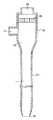
図1は、本発明の医用挿入補助具の一態様のシース部の断面図である。シース部は、近位端から遠位端に通じるルーメン1を有する管形状のシース2と、シースの近位端に接続されシースのルーメンと連通する中空部3を有するシースハブ4から構成される。シースの遠位端5は、近位端側よりも管径の小さい形状とすることが、ダイレータとの密着性を高めるために好ましい。また、シースの遠位端は、近位端側よりもその肉厚を薄くすることが、外径の段差をなくす上で好ましい。シースハブには、ダイレータ挿入口6、分岐管7及び止血弁8が設けられる。
本発明において、シースの材料としては弾性高分子材料を使用することができ曲げ弾性率が通常2,000〜30,000kg/cm2のものが使用される。ショア硬度がA80〜D75の範囲にある弾性高分子材料を好適に使用することができる。ショア硬度が小さくなると、形状が安定しがたくシースの遠位端が反転してめくれるおそれがある。必要に応じて、シース遠位端部に中間部より硬度の大きい材料を使用することができる。ショア硬度が大きくなると、柔軟性が乏しく、キンクしやすいシースとなるおそれがある。また、シースの材料は、常温における10分間の5%延伸において、残留歪みが0.1%以下であることが好ましく、残留歪みが0.01%以下であることがより好ましい。残留歪みが大きい材料はクリープを起こしやすく、医用挿入補助具を体内に設置しているときに、シースの遠位端の密着部の締め付け弾力が低下して、ダイレータ表面からシースの遠位端が浮き上がるおそれがある。本発明においてシースに使用する材料としては、例えば、ポリウレタン、ポリアミド、ポリエステル、ポリエチレン、ポリプロピレン、ポリイソプレンゴム、フッ素樹脂などを挙げることができる。
【0006】
本発明において、シースハブの材料には特に制限はないが、分岐管及び止血弁を設け、ダイレータハブと嵌合させるために適当な弾性と硬度を有する材料であることが好ましく、このような材料としては、例えば、ポリアミド、ポリカーボネート、ポリアセタール、ポリエチレン、ポリプロピレン、ポリ塩化ビニル、ABS樹脂などを挙げることができる。
本発明において、シースハブには、分岐管及び止血弁を設けることが好ましい。分岐管は、シースを通じての体内への薬剤の注入及び体内からの血液の採取などに使用することができる。止血弁は、水密状態を保って、ダイレータ、カテーテルなどをシースに挿入することを可能とし、シースを血管内に留置したとき血液が漏出することを防止する。図2は、止血弁の一態様の斜視図である。止血弁は、円盤状の弾性体9よりなり、円盤の両面を貫通するスリット10を有する。止血弁の材料は、ショア硬度がA20〜A60であることが好ましく、A30〜A50であることがより好ましい。このような弾性体としては、例えば、シリコーンゴム、天然ゴム、ポリウレタン、ポリブタジエン、フッ素ゴムなどを挙げることができる。
図3は、本発明の医用挿入補助具の一態様のダイレータ部の断面図である。ダイレータ部は、近位端から遠位端に通じるルーメン11を有する管形状のダイレータ12と、ダイレータの近位端に接続されルーメン11と連通する中空部13を有するダイレータハブ14から構成される。ダイレータの遠位端15には、遠位端から近位端方向に向かって、しだいに拡径する第一拡径部分16、第一拡径部分よりも緩やかにしだいに拡径する第二拡径部分17及びしだいに縮径する縮径部分18が構成され、外径がほぼ一定の寸胴部分19によって近位端に至る。ダイレータは、シースのルーメン内に挿入することができる。ダイレータの材料としては、ショア硬度が通常A90以上のものが用いられる。具体的には、フッ素樹脂、ポリアミド、ポリエステル、ポリエチレン、ポリプロピレン、ステンレス鋼などが挙げられる。ダイレータの外径により、硬度を変えることが好ましい。例えば、外径1.5mmでは硬度を75Dに、外径3.0mmでは硬度55Dにする。
【0007】
図4は、本発明の医用挿入補助具において、ダイレータがシースのルーメン内に挿入された状態を示す断面図である。ダイレータハブ14とシースハブ4が嵌合され、ダイレータ12がダイレータ挿入口6及び止血弁8を通じてシースのルーメン1内に挿入されている。ダイレータの遠位端15はシースの遠位端5から突出し、シースの遠位端の内壁が、ダイレータの縮径部分18の外壁に密着している。
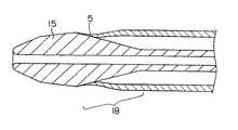
図5は、ダイレータの遠位端近傍の部分断面図である。ダイレータの遠位端には、遠位端から近位端方向に向かって、しだいに拡径する第一拡径部分16、第一拡径部分よりも緩やかにしだいに拡径する第二拡径部分17及びしだいに縮径する縮径部分18が構成され、さらに外径がほぼ一定の寸胴部分19に連続している。ダイレータの大きさ及び形状は、使用する患部に応じて適宜選定することができるが、通常は、第一拡径部分の長さが0.5〜10mm、第二拡径部分が4.5〜90mm、第一拡径部分と第二拡径部分の合計の長さが5〜100mmであり、縮径部分の長さが0.5〜50mmであることが好ましい。ダイレータの外径は、第一拡径部分の開始端において0.5〜3mmであり、第一拡径部分と第二拡径部分の境界において0.6〜4mmであり、第二拡径部分と縮径部分の境界において0.7〜8mmであることが好ましい。縮径部分と寸胴部分の境界における外径は、寸胴部分の外径に等しく、0.5〜7.5mmであることが好ましく、2〜7.5mmであることがより好ましい。第一拡径部分の両端の外径の差すなわち第一拡径部分における拡径量は0.1〜1mmであり、第二拡径部分の両端の外径の差すなわち第二拡径部分における拡径量は0.1〜4mmであり、縮径部分の両端の外径の差すなわち縮径部分における縮径量は0.01〜3mmであることが好ましく、縮径部分における縮径量は0.03〜0.07mmであることがより好ましい。第一拡径部分の開始端、第一拡径部分と第二拡径部分の境界及び第二拡径部分と縮径部分の境界は、稜線を形成することなく、なだらかな曲面で連続することが好ましい。これらの開始端及び境界をなだらかな曲面で連続することにより、医用挿入補助具を血管内へ挿入する際の挿入抵抗を低減することができる。
【0008】
図6は、ダイレータがシースのルーメン内に挿入された状態のダイレータの遠位端近傍の部分断面図である。ダイレータの遠位端15がシースの遠位端5から突出し、ダイレータの縮径部分18において、シースが押し広げられ、シースの遠位端5の内壁が、ダイレータの縮径部分18の外壁に密着している。シースの遠位端の内壁とダイレータの縮径部分の外壁の密着する部分の長さは、1mm以上であることが好ましい。
従来の医用挿入補助具の生体組織への挿入時の挙動を観察したところ、挿入補助具を曲げると、ダイレータとシースとの曲げ性に差があるために、シースの遠位端がダイレータの外壁から離れる。そのため、シースの遠位端が挿入時に生体組織に衝突し、挿入抵抗が増加することが確認された。本発明の医用挿入補助具の挿入時の挙動を観察すると、挿入補助具を曲げてもシースの遠位端はダイレータの外壁に密着した状態が保たれることが確認された。本発明の医用挿入補助具において、生体組織への挿入時の挿入抵抗が低減する理由は、このようにシースの遠位端が生体組織の孔壁に衝突することなく挿入されるためと考えられる。シースの遠位端の内壁が、ダイレータの縮径部分の外壁に密着し、且つ、ダイレータの拡径部分の径が太く、ダイレータの遠位端が曲がりにくくなっているので、ダイレータとシースの曲げ性が同程度になる。本発明の医用挿入補助具を曲げて挿入しても、シースの遠位端がダイレータから離れないので、挿入抵抗が小さくなる。
【0009】
【発明の効果】
本発明の医用挿入補助具によれば、曲げられた状態においてシース遠位端がダイレータ外壁から離れないから、シースの遠位端が生体組織に衝突することがないので、生体組織へ挿入時の抵抗が小さく、患者に不快感や疼痛を与えることがなく、生体組織を傷つけるおそれがない。
【図面の簡単な説明】
【図1】図1は、本発明の医用挿入補助具の一態様のシース部の断面図である。
【図2】図2は、止血弁の一態様の斜視図である。
【図3】図3は、本発明の医用挿入補助具の一態様のダイレータ部の断面図である。
【図4】図4は、本発明の医用挿入補助具において、ダイレータがシースのルーメン内に挿入された状態を示す断面図である。
【図5】図5は、ダイレータの遠位端近傍の部分断面図である。
【図6】図6は、ダイレータがシースのルーメン内に挿入された状態のダイレータの遠位端近傍の部分断面図である。
【符号の説明】
1 ルーメン
2 シース
3 中空部
4 シースハブ
5 シースの遠位端
6 ダイレータ挿入口
7 分岐管
8 止血弁
9 円盤状の弾性体
10 スリット
11 ルーメン
12 ダイレータ
13 中空部
14 ダイレータハブ
15 ダイレータの遠位端
16 第一拡径部分
17 第二拡径部分
18 縮径部分
19 寸胴部分[0001]
BACKGROUND OF THE INVENTION
The present invention relates to a medical insertion aid. More specifically, the present invention relates to a medical insertion assisting tool that includes a sheath and a dilator and has low insertion resistance into a blood vessel.
[0002]
[Prior art]
Diagnosis and treatment using catheters has become widespread, cardiac catheterization method that advances the catheter to the heart under fluoroscopy, measures intracardiac pressure and collects blood, cerebral blood vessels, abdominal blood vessels, peripheral blood vessel contrast diagnostic methods, heart chambers and It is widely used as a treatment for foreign bodies in large blood vessels, patent ductus arteriosus, abnormal blood vessels, and valve stenosis. In order to advance the catheter percutaneously to the target position of the blood vessel, it is necessary to first insert a medical insertion aid into the blood vessel.
To insert the medical insertion aid into the blood vessel, the dilator of the medical insertion aid with the distal end protruding through the sheath is inserted into the guide wire previously inserted into the blood vessel, and the guide wire is inserted into the guide wire. Advancing the medical insertion aid to the target position of the blood vessel. At this time, if the distal end of the medical insertion aid collides with the living tissue, the insertion resistance increases, which may cause discomfort and pain to the patient, as well as damage the living tissue.
Conventionally, various types of medical insertion aids have been proposed in order to reduce the resistance when the medical insertion aid is inserted into a blood vessel. For example, a dilator whose distal end has a rounded shape (Japanese Utility Model Publication No. 6-39723, Japanese Patent Application Laid-Open No. 6-178814), and whose distal end has a tapered portion and a tapered portion (Japanese Utility Model No. 6-44553), a device having a constriction at the distal end (Japanese Patent Laid-Open No. 7-246241), and the like are known. Both of them have a taper shape with the sharpest possible distal end, and conceal the distal end of the sheath behind the bend-shaped portion so that there is no step between the outer diameter of the dilator and the sheath. It aims at reducing the resistance when the distal end of the sheath collides during insertion. However, in reality, when the insertion aid is inserted, a force is applied to the insertion aid to bend. Since the bending of the sheath cannot follow the bending of the dilator, the distal end of the sheath is separated from the outer wall of the dilator, causing a step in the outer diameter, and the insertion resistance was not reduced as expected.
The present inventors previously proposed a medical insertion aid that can bring the distal end of the sheath into close contact with the portion of the dilator that has a diameter reduced from the distal end toward the proximal end. No. 335531), a significant reduction in resistance during insertion into a living tissue has been achieved, but there is a need for a medical insertion aid that can be inserted even more smoothly.
[0003]
[Problems to be solved by the invention]
An object of the present invention is to provide a medical insertion aid that has a low resistance when inserted into a living tissue, does not cause discomfort and pain to a patient, and does not cause a risk of damaging the living tissue.
[0004]
[Means for Solving the Problems]
Since the increase in insertion resistance of the medical insertion aid is due to a step between the sheath and the dilator when bent, the present inventors have a structure in which the step does not occur and the tip of the dilator is not easily bent. As a result, it has been found that the insertion resistance can be significantly reduced, and the present invention has been completed based on this finding.
That is, the present invention
(1) A tube-shaped sheath having a lumen, a sheath hub having a hollow portion connected to the proximal end of the sheath and communicating with the lumen of the sheath, a tube-shaped dilator having a lumen, and a dilator connected to the proximal end of the dilator A dilator hub having a hollow portion that communicates with the lumen of the dilator, wherein the dilator gradually increasesin diameter from the distal end toward the proximal end of the dilator, than the first enlarged portion. It consists of a second diameter-expanded part that gradually increases gradually, a diameter-reduced part that gradually decreases, and an outer diameter part with a substantially constant outer diameter. equal to the outer diameter, with the dilator is inserted into the lumen of the sheath Dairetahabu and sheath hub is fitted, the outer wall the inner wall of the distal end of the sheathis reduced diameter portion of the dilator Medical insertion assisting tool is characterized in that in close contact, and,
(2)the difference between the outer diameter of both ends of the reduced diameter portion of the dilator is from 0.03to0.The a 07Mm(1) medical insertion assisting toolaccording to claim,
Is to provide.
[0005]
DETAILED DESCRIPTION OF THE INVENTION
Hereinafter, the present invention will be described in detail with reference to the drawings.
FIG. 1 is a cross-sectional view of a sheath portion of one embodiment of the medical insertion aid of the present invention. The sheath part includes a tubular sheath 2 having a lumen 1 leading from the proximal end to the distal end, and a sheath hub 4 having a hollow part 3 connected to the proximal end of the sheath and communicating with the lumen of the sheath. The distal end 5 of the sheath is preferably a shape having a smaller tube diameter than the proximal end side in order to improve the adhesion with the dilator. Moreover, it is preferable to make the distal end of the sheath thinner than the proximal end side in order to eliminate the step of the outer diameter. The sheath hub is provided with a
In the present invention, an elastic polymer material can be used as the material of the sheath, and a material having a flexural modulus of usually 2,000 to 30,000 kg / cm2 is used. An elastic polymer material having a Shore hardness in the range of A80 to D75 can be preferably used. If the Shore hardness decreases, the distal end of the sheath may be flipped over because the shape is difficult to stabilize. If necessary, a material harder than the intermediate portion can be used at the sheath distal end. When the Shore hardness is increased, the sheath is poor in flexibility and may be easily kinked. The sheath material preferably has a residual strain of 0.1% or less and more preferably 0.01% or less after 5% stretching for 10 minutes at room temperature. A material with a large residual strain is prone to creep, and when the medical insertion aid is placed in the body, the tightening elasticity of the tight contact portion of the distal end of the sheath is reduced, so that the distal end of the sheath is separated from the dilator surface. There is a risk of floating. Examples of the material used for the sheath in the present invention include polyurethane, polyamide, polyester, polyethylene, polypropylene, polyisoprene rubber, fluororesin and the like.
[0006]
In the present invention, the material of the sheath hub is not particularly limited, but it is preferable to provide a branch pipe and a hemostasis valve and to have a suitable elasticity and hardness for fitting with the dilator hub. Examples thereof include polyamide, polycarbonate, polyacetal, polyethylene, polypropylene, polyvinyl chloride, and ABS resin.
In the present invention, the sheath hub is preferably provided with a branch pipe and a hemostasis valve. The branch tube can be used for injecting a drug into the body through the sheath and collecting blood from the body. The hemostasis valve maintains a watertight state and allows a dilator, a catheter, and the like to be inserted into the sheath, and prevents blood from leaking when the sheath is placed in the blood vessel. FIG. 2 is a perspective view of one embodiment of the hemostasis valve. The hemostasis valve is made of a disk-like elastic body 9 and has slits 10 penetrating both surfaces of the disk. The material of the hemostasis valve preferably has a Shore hardness of A20 to A60, and more preferably A30 to A50. Examples of such elastic bodies include silicone rubber, natural rubber, polyurethane, polybutadiene, and fluorine rubber.
FIG. 3 is a cross-sectional view of a dilator part of one aspect of the medical insertion aid of the present invention. The dilator part is composed of a
[0007]
FIG. 4 is a cross-sectional view showing a state where the dilator is inserted into the lumen of the sheath in the medical insertion aid of the present invention. The
FIG. 5 is a partial cross-sectional view near the distal end of the dilator. The distal end of the dilator has a first diameter-expanded
[0008]
FIG. 6 is a partial cross-sectional view near the distal end of the dilator with the dilator inserted into the lumen of the sheath. The
Observing the behavior of conventional medical insertion aids during insertion into living tissue, bending the insertion aid results in a difference in bendability between the dilator and the sheath, so the distal end of the sheath is the outer wall of the dilator. Get away from. Therefore, it was confirmed that the distal end of the sheath collided with the living tissue at the time of insertion, and the insertion resistance increased. Observation of the behavior during insertion of the medical insertion aid of the present invention confirmed that the distal end of the sheath was kept in close contact with the outer wall of the dilator even when the insertion aid was bent. In the medical insertion aid of the present invention, the reason why the insertion resistance at the time of insertion into a living tissue is reduced is that the distal end of the sheath is inserted without colliding with the hole wall of the living tissue. . Since the inner wall of the distal end of the sheath is in close contact with the outer wall of the reduced diameter portion of the dilator, and the diameter of the enlarged portion of the dilator is large and the distal end of the dilator is difficult to bend, the bending of the dilator and the sheath The sex becomes the same level. Even if the medical insertion aid of the present invention is bent and inserted, the distal end of the sheath does not move away from the dilator, so the insertion resistance is reduced.
[0009]
【The invention's effect】
According to the medical insertion aid of the present invention, since the distal end of the sheath is not separated from the outer wall of the dilator in the bent state, the distal end of the sheath does not collide with the living tissue. Resistance is small, does not cause discomfort and pain to the patient, and does not pose a risk of damaging living tissue.
[Brief description of the drawings]
FIG. 1 is a cross-sectional view of a sheath portion of one embodiment of a medical insertion aid of the present invention.
FIG. 2 is a perspective view of one embodiment of a hemostasis valve.
FIG. 3 is a cross-sectional view of a dilator part of one aspect of the medical insertion aid of the present invention.
FIG. 4 is a cross-sectional view showing a state where the dilator is inserted into the lumen of the sheath in the medical insertion aid of the present invention.
FIG. 5 is a partial cross-sectional view near the distal end of the dilator.
FIG. 6 is a partial cross-sectional view near the distal end of the dilator with the dilator inserted into the lumen of the sheath.
[Explanation of symbols]
DESCRIPTION OF SYMBOLS 1 Lumen 2 Sheath 3 Hollow part 4 Sheath hub 5 Sheath
Claims (2)
Translated fromJapanesePriority Applications (2)
| Application Number | Priority Date | Filing Date | Title |
|---|---|---|---|
| JP05848596AJP3855243B2 (en) | 1996-02-21 | 1996-02-21 | Medical insertion aid |
| PCT/JP1997/000479WO1997030746A1 (en) | 1996-02-21 | 1997-02-21 | Medical insertion assisting tool |
Applications Claiming Priority (1)
| Application Number | Priority Date | Filing Date | Title |
|---|---|---|---|
| JP05848596AJP3855243B2 (en) | 1996-02-21 | 1996-02-21 | Medical insertion aid |
Publications (2)
| Publication Number | Publication Date |
|---|---|
| JPH09225035A JPH09225035A (en) | 1997-09-02 |
| JP3855243B2true JP3855243B2 (en) | 2006-12-06 |
Family
ID=13085740
Family Applications (1)
| Application Number | Title | Priority Date | Filing Date |
|---|---|---|---|
| JP05848596AExpired - Fee RelatedJP3855243B2 (en) | 1996-02-21 | 1996-02-21 | Medical insertion aid |
Country Status (2)
| Country | Link |
|---|---|
| JP (1) | JP3855243B2 (en) |
| WO (1) | WO1997030746A1 (en) |
Families Citing this family (25)
| Publication number | Priority date | Publication date | Assignee | Title |
|---|---|---|---|---|
| JPH0755418A (en)* | 1993-08-13 | 1995-03-03 | Ono Sokki Co Ltd | Displacement gauge |
| US6120480A (en)* | 1997-10-28 | 2000-09-19 | Medtronic Ave, Inc. | Catheter introducer |
| DE60119877T2 (en) | 2000-11-29 | 2007-05-10 | Wollschläger, Helmut, Prof. Dr.med. | Method and device for use in non-invasive surgical procedures |
| JP4675475B2 (en)* | 2000-12-27 | 2011-04-20 | 日本シャーウッド株式会社 | Dilator |
| US6979343B2 (en) | 2001-02-14 | 2005-12-27 | Ev3 Inc. | Rolled tip recovery catheter |
| EP1321163A1 (en)* | 2001-12-19 | 2003-06-25 | C-I-Medic Co., Ltd. | Catheter Assembly |
| US7005026B2 (en)* | 2002-11-15 | 2006-02-28 | Applied Medical Resources Corporation | Kink-resistant access sheath and method of making same |
| US8340779B2 (en) | 2003-08-29 | 2012-12-25 | Medtronic, Inc. | Percutaneous flat lead introducer |
| WO2006135753A1 (en) | 2005-06-09 | 2006-12-21 | Medtronic, Inc. | Introducer for therapy delivery elements |
| JP2007037971A (en)* | 2005-07-05 | 2007-02-15 | Ookiddo:Kk | Catheter assembly and sheath tearing assist |
| JP2008011867A (en)* | 2006-05-25 | 2008-01-24 | Nippon Zeon Co Ltd | Dilator, dilator manufacturing method, and sheath introducer |
| JP2009178518A (en)* | 2008-02-01 | 2009-08-13 | Nipro Corp | Medical tubular body, thrombus capturing member collecting sheath, thrombus collecting catheter, and balloon catheter |
| JP2012085816A (en) | 2010-10-19 | 2012-05-10 | Asahi Intecc Co Ltd | Catheter assembly |
| JP5126910B2 (en) | 2010-10-29 | 2013-01-23 | 朝日インテック株式会社 | Auxiliary dilator and catheter assembly using the same |
| CA2854593C (en)* | 2011-11-04 | 2019-07-16 | Caymus Medical, Inc. | Systems and methods for percutaneous intravascular access and guidewire placement |
| EP2802375B1 (en)* | 2012-01-13 | 2019-03-27 | Teleflex Medical, Incorporated | Novel bumped dilator tip |
| US9474884B2 (en) | 2012-01-13 | 2016-10-25 | Teleflex Medical Incorporated | Bumped dilator tip |
| JP6504816B2 (en) | 2012-03-27 | 2019-04-24 | テルモ株式会社 | Introducer |
| JP5615317B2 (en)* | 2012-04-19 | 2014-10-29 | 保夫 田中 | Lacrimal tract expansion type bougie |
| US10420919B2 (en) | 2015-04-24 | 2019-09-24 | Cook Medical Technologies Llc | Introducer with dynamic dilator and methods of using the same |
| JP2019514523A (en)* | 2016-04-27 | 2019-06-06 | キューエックスメディカル リミテッド ライアビリティ カンパニー | Device and related systems and methods for assisting catheter advancement |
| US11712539B2 (en) | 2016-04-27 | 2023-08-01 | Qxmedical, Llc | Devices for assisting with advancement of catheters and related systems and methods |
| JP6829351B1 (en)* | 2020-07-02 | 2021-02-10 | Umidas株式会社 | Medical device |
| JP7526134B2 (en)* | 2021-05-26 | 2024-07-31 | 朝日インテック株式会社 | Dilator and catheter assembly |
| WO2024090107A1 (en)* | 2022-10-25 | 2024-05-02 | テルモ株式会社 | Catheter |
Family Cites Families (3)
| Publication number | Priority date | Publication date | Assignee | Title |
|---|---|---|---|---|
| JP2604991Y2 (en)* | 1992-11-25 | 2000-06-12 | 東郷メディキット株式会社 | Catheter introducer |
| JPH06335531A (en)* | 1993-04-22 | 1994-12-06 | Nippon Zeon Co Ltd | Introducer |
| JP2974893B2 (en)* | 1993-08-18 | 1999-11-10 | 住友ベークライト株式会社 | Drainage tube |
- 1996
- 1996-02-21JPJP05848596Apatent/JP3855243B2/ennot_activeExpired - Fee Related
- 1997
- 1997-02-21WOPCT/JP1997/000479patent/WO1997030746A1/enactiveApplication Filing
Also Published As
| Publication number | Publication date |
|---|---|
| JPH09225035A (en) | 1997-09-02 |
| WO1997030746A1 (en) | 1997-08-28 |
Similar Documents
| Publication | Publication Date | Title |
|---|---|---|
| JP3855243B2 (en) | Medical insertion aid | |
| US5336205A (en) | Flow directed catheter | |
| JP4940390B2 (en) | Medical device having knitted structure and coil | |
| US8262619B2 (en) | Introducer sheath for catheters | |
| JPH10216237A (en) | Stylet and device including the stylet | |
| WO1990002579A2 (en) | Catheter introducer with flexible tip | |
| JP2005312894A (en) | Stent with flexible element | |
| CN114768052A (en) | Introducer sheath for vascular access | |
| JP4900242B2 (en) | Aortic balloon pumping set | |
| US20210260355A1 (en) | Valved introducer sheath | |
| CN112739405A (en) | Introducer for uterine packing assembly with echo element | |
| JPH09225036A (en) | Medical insertion aid | |
| JP2002143318A (en) | Assembly of an introducing catheter and a diagnostic treatment catheter | |
| JPH07265432A (en) | Work hardening type non-shape memory alloy catheter | |
| JPH08182765A (en) | Introducer | |
| US20210290904A1 (en) | Catheter assembly | |
| JP6813570B2 (en) | Percutaneous catheter | |
| JPH0434914B2 (en) | ||
| JP5439886B2 (en) | Medical dilator | |
| JPH07184846A (en) | Trocar apparatus | |
| JP4174277B2 (en) | Dilatation balloon catheter | |
| JP2723190B2 (en) | Indwelling needle | |
| CN209996995U (en) | novel guide wires | |
| JPH0530469B2 (en) | ||
| JP3446353B2 (en) | Drainage equipment |
Legal Events
| Date | Code | Title | Description |
|---|---|---|---|
| A131 | Notification of reasons for refusal | Free format text:JAPANESE INTERMEDIATE CODE: A131 Effective date:20051213 | |
| A521 | Written amendment | Free format text:JAPANESE INTERMEDIATE CODE: A523 Effective date:20060213 | |
| A521 | Written amendment | Free format text:JAPANESE INTERMEDIATE CODE: A821 Effective date:20060215 | |
| A131 | Notification of reasons for refusal | Free format text:JAPANESE INTERMEDIATE CODE: A131 Effective date:20060522 | |
| TRDD | Decision of grant or rejection written | ||
| A01 | Written decision to grant a patent or to grant a registration (utility model) | Free format text:JAPANESE INTERMEDIATE CODE: A01 Effective date:20060821 | |
| A61 | First payment of annual fees (during grant procedure) | Free format text:JAPANESE INTERMEDIATE CODE: A61 Effective date:20060903 | |
| R150 | Certificate of patent or registration of utility model | Free format text:JAPANESE INTERMEDIATE CODE: R150 | |
| FPAY | Renewal fee payment (event date is renewal date of database) | Free format text:PAYMENT UNTIL: 20100922 Year of fee payment:4 | |
| FPAY | Renewal fee payment (event date is renewal date of database) | Free format text:PAYMENT UNTIL: 20110922 Year of fee payment:5 | |
| FPAY | Renewal fee payment (event date is renewal date of database) | Free format text:PAYMENT UNTIL: 20110922 Year of fee payment:5 | |
| FPAY | Renewal fee payment (event date is renewal date of database) | Free format text:PAYMENT UNTIL: 20120922 Year of fee payment:6 | |
| FPAY | Renewal fee payment (event date is renewal date of database) | Free format text:PAYMENT UNTIL: 20130922 Year of fee payment:7 | |
| LAPS | Cancellation because of no payment of annual fees |