JP3853963B2 - Power unit - Google Patents
Power unitDownload PDFInfo
- Publication number
- JP3853963B2 JP3853963B2JP07180298AJP7180298AJP3853963B2JP 3853963 B2JP3853963 B2JP 3853963B2JP 07180298 AJP07180298 AJP 07180298AJP 7180298 AJP7180298 AJP 7180298AJP 3853963 B2JP3853963 B2JP 3853963B2
- Authority
- JP
- Japan
- Prior art keywords
- transmission
- continuously variable
- chamber
- engine
- oil
- Prior art date
- Legal status (The legal status is an assumption and is not a legal conclusion. Google has not performed a legal analysis and makes no representation as to the accuracy of the status listed.)
- Expired - Fee Related
Links
Images


Classifications
- F—MECHANICAL ENGINEERING; LIGHTING; HEATING; WEAPONS; BLASTING
- F16—ENGINEERING ELEMENTS AND UNITS; GENERAL MEASURES FOR PRODUCING AND MAINTAINING EFFECTIVE FUNCTIONING OF MACHINES OR INSTALLATIONS; THERMAL INSULATION IN GENERAL
- F16H—GEARING
- F16H57/00—General details of gearing
- F16H57/04—Features relating to lubrication or cooling or heating
- F16H57/048—Type of gearings to be lubricated, cooled or heated
- F16H57/0487—Friction gearings
- F—MECHANICAL ENGINEERING; LIGHTING; HEATING; WEAPONS; BLASTING
- F16—ENGINEERING ELEMENTS AND UNITS; GENERAL MEASURES FOR PRODUCING AND MAINTAINING EFFECTIVE FUNCTIONING OF MACHINES OR INSTALLATIONS; THERMAL INSULATION IN GENERAL
- F16H—GEARING
- F16H15/00—Gearings for conveying rotary motion with variable gear ratio, or for reversing rotary motion, by friction between rotary members
- F16H15/02—Gearings for conveying rotary motion with variable gear ratio, or for reversing rotary motion, by friction between rotary members without members having orbital motion
- F16H15/04—Gearings providing a continuous range of gear ratios
- F16H15/06—Gearings providing a continuous range of gear ratios in which a member A of uniform effective diameter mounted on a shaft may co-operate with different parts of a member B
- F16H15/16—Gearings providing a continuous range of gear ratios in which a member A of uniform effective diameter mounted on a shaft may co-operate with different parts of a member B in which the member B has a conical friction surface
- F16H15/18—Gearings providing a continuous range of gear ratios in which a member A of uniform effective diameter mounted on a shaft may co-operate with different parts of a member B in which the member B has a conical friction surface externally
- F16H15/20—Gearings providing a continuous range of gear ratios in which a member A of uniform effective diameter mounted on a shaft may co-operate with different parts of a member B in which the member B has a conical friction surface externally co-operating with the outer rim of the member A, which is perpendicular or nearly perpendicular to the friction surface of the member B
- F—MECHANICAL ENGINEERING; LIGHTING; HEATING; WEAPONS; BLASTING
- F16—ENGINEERING ELEMENTS AND UNITS; GENERAL MEASURES FOR PRODUCING AND MAINTAINING EFFECTIVE FUNCTIONING OF MACHINES OR INSTALLATIONS; THERMAL INSULATION IN GENERAL
- F16H—GEARING
- F16H61/00—Control functions within control units of change-speed- or reversing-gearings for conveying rotary motion ; Control of exclusively fluid gearing, friction gearing, gearings with endless flexible members or other particular types of gearing
- F16H61/66—Control functions within control units of change-speed- or reversing-gearings for conveying rotary motion ; Control of exclusively fluid gearing, friction gearing, gearings with endless flexible members or other particular types of gearing specially adapted for continuously variable gearings
- F16H61/664—Friction gearings
- F16H61/6646—Friction gearings controlling shifting exclusively as a function of speed
- F—MECHANICAL ENGINEERING; LIGHTING; HEATING; WEAPONS; BLASTING
- F16—ENGINEERING ELEMENTS AND UNITS; GENERAL MEASURES FOR PRODUCING AND MAINTAINING EFFECTIVE FUNCTIONING OF MACHINES OR INSTALLATIONS; THERMAL INSULATION IN GENERAL
- F16H—GEARING
- F16H57/00—General details of gearing
- F16H57/02—Gearboxes; Mounting gearing therein
- F16H2057/0203—Gearboxes; Mounting gearing therein the gearbox is associated or combined with a crank case of an engine
- Y—GENERAL TAGGING OF NEW TECHNOLOGICAL DEVELOPMENTS; GENERAL TAGGING OF CROSS-SECTIONAL TECHNOLOGIES SPANNING OVER SEVERAL SECTIONS OF THE IPC; TECHNICAL SUBJECTS COVERED BY FORMER USPC CROSS-REFERENCE ART COLLECTIONS [XRACs] AND DIGESTS
- Y10—TECHNICAL SUBJECTS COVERED BY FORMER USPC
- Y10T—TECHNICAL SUBJECTS COVERED BY FORMER US CLASSIFICATION
- Y10T74/00—Machine element or mechanism
- Y10T74/21—Elements
- Y10T74/2186—Gear casings
Landscapes
- Engineering & Computer Science (AREA)
- General Engineering & Computer Science (AREA)
- Mechanical Engineering (AREA)
- Friction Gearing (AREA)
- General Details Of Gearings (AREA)
- Control Of Transmission Device (AREA)
Description
Translated fromJapanese【0001】
【発明の属する技術分野】
本発明は、エンジンの駆動力が入力される入力回転軸の回転を無段変速して出力する無段変速機とエンジンとを含むパワーユニットに関する。
【0002】
【従来の技術】
コーン状に形成された変速回転部材の母線に沿って伝達回転部材の接触位置を連続的に変化させることにより無段変速を行う無段変速機は、例えば特開平9−177919号公報、特開平9−177920号公報、特開平9−236161号公報に記載されているように既に知られている。上記従来の無段変速機は、変速機主軸に設けたドリブンギヤをキャリア(コーンホルダ)に形成した窓孔に臨ませ、クランクシャフトに設けたドライブギヤを前記ドリブンギヤに歯合させることにより、エンジンの駆動力を変速機主軸に入力するようになっている。
【0003】
【発明が解決しようとする課題】
しかしながら、変速機主軸に設けたドリブンギヤをキャリアの内部に収納すると該キャリアを小型化することができず、そのために無段変速機全体が大型化してしまう問題があるだけでなく、ドリブンギヤの外径を自由に変更することができないために、エンジンから無段変速機に伝達される駆動力の変速比を自由に設定することが難しくなる問題がある。
【0004】
本発明は前述の事情に鑑みてなされたもので、無段変速機を小型化するとともに、エンジンから無段変速機に伝達される駆動力の変速比を自由に設定できるようにすることを目的とする。
【0005】
【課題を解決するための手段】
上記目的を達成するために、請求項1に記載された発明は、入力回転軸の回転を無段変速して出力する無段変速機と、この無段変速機に連動する有段の副変速機と、前記入力回転軸に駆動力を与えるエンジンとを含むパワーユニットであって、前記エンジンのクランクケースを兼ねる、パワーユニットのケーシング内に、該エンジンのクランク室と、このクランク室から隔離されて前記無段変速機及び前記副変速機を収納し且つ潤滑油を封入された変速機室とを区画するカバー部材を設け、前記入力回転軸の一部を、前記カバー部材を貫通して前記変速機室から前記クランク室側に突出させ、その突出部には、前記クランク室に臨んでいて前記エンジンの駆動力を該入力回転軸に伝達する駆動力伝達部材を固定し、更に前記突出部には、前記変速機室の外側に配置されて前記無段変速機及び前記副変速機に前記潤滑油を強制循環させるオイルポンプを連結し、前記入力回転軸が前記カバー部材を貫通する部分にシール部材を設けたことを特徴とする。
【0006】
上記構成によれば、パワーユニットのケーシング内に、エンジンのクランク室と、このクランク室から隔離されて無段変速機及び副変速機を収納し且つ潤滑油を封入された変速機室とを区画するカバー部材を設け、無段変速機の入力回転軸の一部を、前記カバー部材を貫通して変速機室からクランク室側に突出させ、その突出部には、クランク室に臨んでいてエンジンの駆動力を入力する駆動力伝達部材を固定したので、前記駆動力伝達部材によって無段変速機や変速機室の寸法が大型化するのを防止することができる。またクランク室から隔離され潤滑油を封入された変速機室に無段変速機及び副変速機を収納したので、無段変速機及び副変速機の潤滑系をエンジンの潤滑系から分離して該無段変速機及び副変速機を過不足なく安定して潤滑することができる。また入力回転軸が前記カバー部材を貫通する部分にシール部材を設け、このシール部材でシールすることにより、変速機室に封入した潤滑油のクランク室への漏出を防止することができる。
【0007】
また請求項2に記載された発明は、請求項1の構成に加えて、前記駆動力伝達部材が、前記エンジンのクランクシャフトにより駆動されるドライブギヤに前記クランク室内で噛合するドリブンギヤであることを特徴とする。
【0008】
上記構成によれば、上記ギヤの外径を変化させるだけで無段変速機に伝達される駆動力の変速比を自由に設定することができる。
【0009】
また請求項3に記載された発明は、請求項1又は2の構成に加えて、前記入力回転軸により前記オイルポンプが駆動されると、前記変速機室の底部のオイル溜めから、前記パワーユニットのケーシングに設けた油路を経て前記潤滑油が該オイルポンプに吸い上げられ、さらに該オイルポンプから、前記入力回転軸に設けた油路を経て前記潤滑油が前記変速機室内部の前記無段変速機及び前記副変速機に供給されることを特徴とする。
【0010】
【発明の実施の形態】
以下、本発明の実施形態を、添付図面に示した本発明の実施例に基づいて説明する。
【0011】
図1〜図6は本発明の一実施例を示すもので、図1は車両用パワーユニットの縦断面図、図2は無段変速機の拡大図、図3は図2の要部拡大図(LOWレシオ)、図4は図2の要部拡大図(TOPレシオ)、図5は図2の5−5線断面図、図6は図2の6−6線断面図である。
【0012】
図1に示すように、このパワーユニットPは自動二輪車に搭載されるものであって、エンジンE、無段変速機Tおよび副変速機Rを収納するケーシング1を備える。ケーシング1はエンジンEのクランクケースを兼ねるもので、センターケーシング2と、センターケーシング2の左側面に結合される左ケーシング3と、センターケーシング2の右側面に結合される右ケーシング4とに3分割される。センターケーシング2および左ケーシング3に一対のボールベアリング5,5を介して支持されたクランクシャフト6は、同じくセンターケーシング2および左ケーシング3に支持されたシリンダブロック7に摺動自在に嵌合するピストン8にコネクティングロッド9を介して連接される。
【0013】
クランクシャフト6の左端には発電機10が設けられており、この発電機10は左ケーシング3の左側面に結合された発電機カバー11により覆われる。右ケーシング4の内部に延出するクランクシャフト6の右端外周にドライブギヤ12が相対回転自在に支持されており、このドライブギヤ12は自動遠心クラッチ13によってクランクシャフト6に結合可能である。
【0014】
図2を併せて参照すると明らかなように、無段変速機Tの変速機主軸21(本発明の入力回転軸)には前記ドライブギヤ12に噛合するドリブンギヤ25が固定される。ドリブンギヤ25は変速機主軸21にスプライン結合された内側ギヤ半体26と、この内側ギヤ半体26に複数個のゴムダンパー28…を介して僅かに相対回転し得るように結合されて前記ドライブギヤ12に噛合する外側ギヤ半体27とから構成される。ドライブギヤ12からドリブンギヤ25を経て変速機主軸21に伝達されるエンジントルクが変動したとき、前記ゴムダンパー28…の変形によりショックの発生が軽減される。
【0015】
次に、図2を参照して前記無段変速機Tの構造を説明する。
【0016】
変速機主軸21の外周には、半径方向外側を向く摩擦接触面を備えた駆動回転部材29がスプライン結合されるとともに、半径方向内側を向く摩擦接触面を備えた従動回転部材30がニードルベアリング22を介して相対回転自在に支持される。概略円錐状に形成されたキャリア第1半体31が変速機主軸21の外周にニードルベアリング23を介して相対回転可能且つ軸方向摺動可能に支持され、このキャリア第1半体31に概略カップ状のキャリア第2半体32が結合される。
【0017】
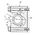
図5を併せて参照すると明らかなように、両キャリア半体31,32をケーシング1に対して回り止めするトルクカム機構33は、キャリア第2半体32の外周に半径方向に植設したピン34と、このピン34に回転自在に支持したローラ36と、右ケーシング4の内壁面にボルト24,24で固定したガイドブロック35とから構成されており、このガイドブロック35に形成したガイド溝351に前記ローラ36が係合する。ガイド溝351の方向は変速機主軸21の軸線Lに対して角度αだけ傾斜している。
【0018】
図3および図4から明らかなように、キャリア第1半体31に形成された複数の窓孔311…を横切るように複数の支持軸37…が架設されており、各支持軸37にニードルベアリング38,38を介して変速回転部材39が回転自在且つ軸方向摺動自在に支持される。支持軸37…は変速機主軸21の軸線Lを中心線とする円錐母線上に配置されている。各変速回転部材39は大径部において接続された円錐状の第1摩擦伝達面40および第2摩擦伝達面41を有しており、第1摩擦伝達面40は駆動回転部材29に第1接触部P1において当接するとともに、第2摩擦伝達面41は従動回転部材30に第2接触部P2において当接する。
【0019】
図2に示すように、キャリア第2半体32の内部に、変速機主軸21の回転数に応じて両キャリア半体31,32を軸方向に摺動させて無段変速機Tの変速比を変更する遠心ガバナ51が設けられる。遠心ガバナ51は、変速機主軸21に固定された固定カム部材52と、変速機主軸21に軸方向摺動自在に支持されて前記固定カム部材52と一体に回転する可動カム部材53と、固定カム部材52のカム面521および可動カム部材53のカム面531間に配置された複数の遠心ウエイト54…とから構成される。可動カム部材53とキャリア第2半体32とをボールベアリング55で結合することにより、両者は相対回転を許容された状態で軸方向に一体に移動する。
【0020】
変速機主軸21の右端近傍はセンターケーシング2に固定したカバー部材50にボールベアリング56を介して支持されており、そのカバー部材50とキャリア第2半体32との間に縮設したスプリング57の弾発力で、キャリア第1半体31およびキャリア第2半体32は左方向に付勢される。従って、変速機主軸21の回転数が増加すると遠心力で遠心ウエイト54…が半径方向外側に移動して両カム面521,531を押圧するため、可動カム部材53がスプリング57の弾発力に抗して右方向に移動し、この可動カム部材53にボールベアリング55を介して接続されたキャリア第2半体32がキャリア第1半体31と共に右方向に移動する。
【0021】
図2から明らかなように、変速機主軸21の外周にボールベアリング58を介して相対回転自在に支持された出力ギヤ59の右端と、前記従動回転部材30の左端との間に調圧カム機構60が設けられる。図6を併せて参照すると明らかなように、調圧カム機構60は、出力ギヤ59の右端に形成した複数の凹部591…と従動回転部材30の左端に形成した複数の凹部301…との間にボール61…を挟持したものであり、出力ギヤ59と従動回転部材30との間には従動回転部材30を右方向に付勢する予荷重を与えるように皿バネ62が介装される。従動回転部材30にトルクが作用して出力ギヤ59との間に相対回転が生じると、調圧カム機構60により従動回転部材30が出力ギヤ59から離反する方向(右方向)に付勢される。
【0022】
次に、図2を参照して前記副変速機Rの構造を説明する。
【0023】
第3減速ギヤ63が、左ケーシング3との間に配置したボールベアリング64、変速機主軸21との間に配置したニードルベアリング65および出力ギヤ59との間に配置したボールベアリング66によって回転自在に支持される。左ケーシング3および中央ケーシング2にボールベアリング67およびニードルベアリング68を介して減速軸69が支持されており、減速軸69に支持した第1減速ギヤ70および第2減速ギヤ71がそれぞれ前記出力ギヤ59および第3減速ギヤ63に噛合する。第3減速ギヤ63と一体に形成されて左ケーシング3から外部に突出する最終出力軸631に、無端チェーン72を巻き掛けた駆動スプロケット73が設けられる。従って、変速機主軸21の回転は出力ギヤ59、第1減速ギヤ70、第2減速ギヤ71、第3減速ギヤ63、駆動スプロケット73および無端チェーン72を介して駆動輪に伝達される。
【0024】
前記第1減速ギヤ70は減速軸69に対して相対回転自在に支持されており、この第1減速ギヤ70を減速軸69に締結および締結解除すべく、ドグクラッチよりなるニュートラルクラッチ76が設けられる。ニュートラルクラッチ76は減速軸69に軸方向摺動自在にスプライン結合されたシフター77と、ライダーにより操作される図示せぬ操作部材に連動して前記シフター77を摺動させるフォーク78とを備える。従って、フォーク78でシフター77を図中左側に移動させると、シフター77のドグ歯771と第1減速ギヤ70のドグ歯701とが噛合し、第1減速ギヤ70がシフター77を介して減速軸69に結合される。逆に、フォーク78でシフター77を図中右側に移動させると、シフター77のドグ歯771と第1減速ギヤ70のドグ歯701とが離反し、第1減速ギヤ70と減速軸69との結合が解除される。
【0025】
自動二輪車を押して移動させるとき、車輪の回転が副変速機Rから無段変速機Tに逆伝達されると、無段変速機Tの各部の摩擦力に打ち勝つ大きな力で自動二輪車を押す必要がある。しかしながら、このときにニュートラルクラッチ76を締結解除すれば、副変速機Rの第1減速ギヤ70が減速軸69から切り離されて無段変速機Tへの駆動力の逆伝達が防止され、軽い力で押すだけで自動二輪車を移動させることができる。
【0026】
次に、無段変速機Tおよび副変速機Rの潤滑構造を説明する。
【0027】
図2に示すように、無段変速機Tおよび副変速機Rは、左ケーシング3、センターケーシング2およびカバー50によって区画された変速機室79の内部に収納される。カバー部材50を貫通する変速機主軸21の外周をシール部材80でシールすることにより、変速機室79はクランク室14の内部空間に対して分離されている。無段変速機Tおよび副変速機Rは変速機室79内に封入された潤滑油により潤滑され、またエンジンEはクランク室14内に貯留された潤滑油により潤滑されるため、それぞれの潤滑油は相互に混じり合うことがない。即ち、クランク室14の底部に貯留された潤滑油は、変速機主軸21に設けたドリブンギヤ25により攪拌されてエンジンEの各部を潤滑する。一方、無段変速機Tおよび副変速機Rは、変速機主軸21の軸端に設けたオイルポンプ81によって循環する潤滑油で潤滑される。
【0028】
トロコイドポンプよりなるオイルポンプ81は、右ケーシング4にボルト82で固定されたポンプハウジング83と、ポンプハウジング83にボルト84で固定されたポンプカバー85と、ポンプハウジング83に回転自在に収納されたアウターロータ86と、アウターロータ86の内周に回転自在に歯合するインナーロータ87とから構成されており、前記インナーロータ87はポンプハウジング83をシール部材88を介して貫通する変速機主軸21の右端に固定される。
【0029】
変速機室79の下部に形成されたオイル溜め89の右側にはオイルフィルター90を収納したフィルター室91が設けられており、このフィルター室91の下流側とオイルポンプ81の吸入ポート851とが、右ケーシング4に形成した油路41およびポンプハウジング83に形成した油路831を介して連通する。またオイルポンプ81の吐出ポート852は、変速機主軸21の内部を軸方向に貫通する油路211と、その油路211から半径方向に分岐する複数の油路212…とに連通する。
【0030】
次に、前述の構成を備えた本発明の実施例の作用について説明する。
【0031】
図3および図4に示すように、変速比が何れの状態でも変速機主軸21の軸線Lから測った駆動回転部材29の第1接触部P1の距離Aは一定値となり、支持軸37から測った駆動回転部材29の第1接触部P1の距離Bは可変値(BL,BT)となる。また、支持軸37から測った従動回転部材30の第2接触部P2の距離Cは可変値(CL,CT)となり、変速機主軸21の軸線Lから測った従動回転部材30の第2接触部P2の距離Dは一定値となる。
【0032】
駆動回転部材29の回転数をNDRとし、従動回転部材30の回転数をNDNとして変速比RをR=NDR/NDNで定義すると、変速比Rは、
R=NDR/NDN=(B/A)×(D/C)
により与えられる。
【0033】
さて、図3に示すように、エンジンEの低速回転時にはドライブギヤ12により駆動されるドリブンギヤ25の回転数が低いため、遠心ガバナ51の遠心ウエイト54…に作用する遠心力も小さくなり、両キャリア半体31,32はスプリング57の弾発力で左方向に移動する。キャリア第1半体31が左方向に移動すると、駆動回転部材29の第1接触部P1が第1摩擦伝達面40の大径部側に移動して距離Bは最大値BLに増加するとともに、従動回転部材30の第2接触部P2が第2摩擦伝達面41の小径部側に移動して距離Cが最小値CLに減少する。 このとき、前記距離A,Dは一定値であるため、距離Bが最大値BLに増加し、距離Cが最小値CLに減少すると、前記変速比Rが大きくなってLOWレシオに変速される。
【0034】
一方、図4に示すように、エンジンEの高速回転時にはドライブギヤ12により駆動されるドリブンギヤ25の回転数が高いため、遠心ガバナ51の遠心ウエイト54…に作用する遠心力も大きくなり、両キャリア半体31,32は遠心力で半径方向外側に移動する遠心ウエイト54…の作用でスプリング57の弾発力に抗して右方向に移動する。キャリア第1半体31が右方向に移動すると、駆動回転部材29の第1接触部P1が第1摩擦伝達面40の小径部側に移動して距離Bが最小値BTに減少するとともに、従動回転部材30の第2接触部P2が第2摩擦伝達面41の大径部側に移動して距離Cが最大値CTに増加する。
【0035】
このとき、前記距離A,Dは一定値であるため、距離Bが最小値BTに減少し、距離Cが最大値CTに増加すると、前記変速比Rが小さくなってTOPレシオに変速される。
【0036】
而して、エンジンEの回転数に応じて無段変速機Tの変速比をLOWとTOPとの間で無段階に変化させることができる。しかも前記変速比制御は遠心ガバナ51により自動的に行われるため、ケーシング1の外部から手動により変速操作を行う変速制御装置を設ける場合や、電子的な変速制御装置を設ける場合に比べて、構造の簡略化によるコストの削減と無段変速機Tの小型化とを図ることができる。
【0037】
上述のようにして駆動回転部材29の回転は変速回転部材39…を介して従動回転部材30に所定の変速比Rで伝達され、更に従動回転部材30の回転は調圧カム機構60を介して出力ギヤ59に伝達される。このとき、従動回転部材30に作用するトルクで出力ギヤ59との間に相対回転が生じると、調圧カム機構60により従動回転部材30が出力ギヤ59から離反する方向に付勢される。この付勢力は皿バネ62による付勢力と協働して、駆動回転部材29の第1接触部P1を第1摩擦伝達面40に圧接する面圧と、従動回転部材30の第2接触部P2を第2摩擦伝達面41に圧接する面圧とを発生させる。
【0038】
ところで、無段変速機Tが変速を行っているとき、キャリア第2半体32は駆動回転部材29の伝達トルク反力によって変速機主軸21回りに回転しようとするが、その伝達トルク反力はキャリア第2半体32に支持したトルクカム機構33のローラ36がガイドブロック35に形成したガイド溝351に係合することにより受け止められ、両キャリア半体31,32は回転することなく軸方向に摺動することができる。
【0039】
さて、車両の走行中に急加速しようとしてエンジントルクを急増させた場合、前記エンジントルクの急増に伴ってキャリア第2半体32に作用する伝達トルク反力も増大する。その結果、図5に示すように、ローラ36が傾斜したガイド溝351の壁面に荷重Fで圧接され、その荷重Fのガイド溝351方向の成分F1によってキャリア第2半体32は図2の左側(LOWレシオ側)に付勢される。即ち、トルクカム機構33の作用によって変速比が自動的にLOWレシオ側に変化するため、所謂キックダウン効果が発揮されて車両を効果的に加速することができる。
【0040】
しかも前記キックダウン時の変速比制御は、特別の変速制御装置を設けることなく、トルクカム機構33がエンジントルクの変化に応じて自動的に行うため、構造の簡略化によるコストの削減と無段変速機Tの小型化とを達成することができる。またトルクカム機構33のガイド溝351の形状を変化させるだけで、変速比の変化特性を容易に調整することができる。
【0041】
さて、無段変速機Tおよび副変速機Rの運転中に変速機主軸21によりオイルポンプ81が駆動されると、変速機室79の底部のオイル溜め89からオイルフィルター90、右ケーシング4の油路41、ポンプハウジング83の油路831およびポンプカバー85の吸入ポート851を経て吸い上げられた潤滑油は、ポンプカバー85の吐出ポート852および変速機主軸21の油路211,212…を経て変速機室79の内部に供給される。変速機室79の内部に供給された潤滑油は、無段変速機Tの変速回転部材39の第1摩擦伝達面40および第2摩擦伝達面41や、無段変速機Tおよび副変速機Rの各ベアリングやギヤの歯合部を潤滑した後、前記オイル溜め89に還流する。
【0042】
このように、無段変速機Tおよび副変速機Rの潤滑系をエンジンEの潤滑系から独立して設けることにより、それら無段変速機Tおよび副変速機Rを過不足なく安定して潤滑することができる。またオイルポンプ81を変速機主軸21の軸端部に設けて直接駆動しているので、オイルポンプ81をクランクシャフト6で駆動する場合に比べて、オイルポンプ81と無段変速機Tとを接近させて潤滑油の油路を短縮することができ、しかも変速機主軸21の回転をオイルポンプ81に伝達する動力伝達系の構造を簡素化することができる。特に、オイルポンプ81を駆動する変速機主軸21の内部と、オイルポンプ81を支持する右ケーシング4の内部とに潤滑油の油路211,212…,41を形成したので、それら油路を構成するための特別の部材が不要になって部品点数が削減される。
【0043】
また無段変速機Tの変速機主軸21に駆動力を伝達するドリブンギヤ25を変速機室79を区画するカバー部材50の外部に設けたので、ドリブンギヤ25によって無段変速機Tおよび変速機室79が大型化するのを防止するとともに、ドリブンギヤ25の寸法を変速機室79の容積に関わらずに任意に設定して、変速機主軸25に入力される駆動力の変速比を変化させることができる。
【0044】
以上、本発明の実施例を詳述したが、本発明はその要旨を逸脱しない範囲で種々の設計変更を行うことが可能である。
【0045】
例えば、本発明は実施例で説明した無段変速機以外の任意の構造の無段変速機に対して適用することができる。
【0046】
【発明の効果】
以上のように本発明によれば、パワーユニットのケーシング内に、エンジンのクランク室と、このクランク室から隔離されて無段変速機及び副変速機を収納し且つ潤滑油を封入された変速機室とを区画するカバー部材を設け、無段変速機の入力回転軸の一部を、前記カバー部材を貫通して変速機室からクランク室側に突出させ、その突出部には、クランク室に臨んでいてエンジンの駆動力を入力する駆動力伝達部材を固定したので、前記駆動力伝達部材によって無段変速機や変速機室の寸法が大型化するのを防止することができる。またクランク室から隔離され潤滑油を封入された変速機室に無段変速機及び副変速機を収納したので、無段変速機及び副変速機の潤滑系をエンジンの潤滑系から分離して該無段変速機及び副変速機を過不足なく安定して潤滑することができる。また入力回転軸が前記カバー部材を貫通する部分にシール部材を設け、このシール部材でシールすることにより、変速機室に封入した潤滑油のクランク室への漏出を防止することができる。
【0047】
また特に請求項2の発明によれば、エンジンの駆動力を入力回転軸に伝達する駆動力伝達部材を、エンジンのクランクシャフトにより駆動されるドライブギヤにクランク室内で噛合するドリブンギヤで構成することにより、該ギヤの外径を変化させるだけで無段変速機に伝達される駆動力の変速比を自由に設定することができる。
【図面の簡単な説明】
【図1】 車両用パワーユニットの縦断面図
【図2】 無段変速機の拡大図
【図3】 図2の要部拡大図(LOWレシオ)
【図4】 図2の要部拡大図(TOPレシオ)
【図5】 図2の5−5線断面図
【図6】 図2の6−6線断面図
【符号の説明】
1ケーシング
41油路
12 ドライブギヤ
14 クランク室
21 変速機主軸(入力回転軸)
211,212油路
25 ドリブンギヤ(ギヤ)
50 カバー部材
51 遠心ガバナ
79 変速機室
80 シール部材
81オイルポンプ
89オイル溜め
E エンジン
P パワーユニット
R副変速機
T 無段変速機[0001]
BACKGROUND OF THE INVENTION
The present invention relates to rotation of the input rotary shaft to which the driving force of the engine is inputtedto the power unit comprising a continuously variable transmissionand an engine to output the continuously variable transmission.
[0002]
[Prior art]
A continuously variable transmission that performs a continuously variable transmission by continuously changing the contact position of the transmission rotating member along the generatrix of the transmission rotating member formed in a cone shape is disclosed in, for example, Japanese Patent Laid-Open Nos. 9-177919 and Hei. It is already known as described in JP-A-9-177920 and JP-A-9-236161. In the conventional continuously variable transmission, the driven gear provided on the transmission main shaft faces the window hole formed in the carrier (cone holder), and the drive gear provided on the crankshaft is engaged with the driven gear, thereby The driving force is input to the transmission main shaft.
[0003]
[Problems to be solved by the invention]
However, if the driven gear provided on the transmission main shaft is housed in the carrier, the carrier cannot be reduced in size, and thus the entire continuously variable transmission is not only enlarged, but also the outer diameter of the driven gear. Since it cannot be freely changed, there is a problem that it is difficult to freely set the gear ratio of the driving force transmitted from the engine to the continuously variable transmission.
[0004]
The present invention has been made in view of the above-described circumstances, and aims to reduce the size of a continuously variable transmission and to freely set the gear ratio of the driving force transmitted from the engine to the continuously variable transmission. And
[0005]
[Means for Solving the Problems]
In order to achieve the above object, a first aspect of the present invention is a continuously variable transmission that outputs a rotation of an input rotary shaft by continuously variable transmission, anda stepped sub-transmission that is linked to the continuously variable transmission. and machine,a power unit comprising an engine applying a driving force to the input rotaryshaft, also serves as a crank case of the engine, in the power unit of the casing, a crank chamber of the engine, is isolated from the crank chamber the A cover member that divides the continuously variable transmissionand the auxiliary transmission and that defines a transmission chamber filled with lubricating oil is provided, and a part of the input rotation shaft passes through the cover member and the transmission A driving force transmitting member that faces the crank chamber and transmits the driving force of the engine to the input rotation shaft is fixed to theprotruding portion; The above Is arranged outside the speed machine chamber by connecting the oil pump to force circulate the lubricating oil to the continuously variable transmission and the auxiliary transmission, a seal member provided in a portion of the input rotary shaft extending through the cover member It is characterized by that.
[0006]
According to the above configuration, the engine crank chamber and the transmission chamber which is isolated from the crank chamber and houses the continuously variable transmissionand the sub-transmission and is filled with lubricating oil are partitioned in the casing of the power unit. A cover member is provided, and a part of the input rotary shaft of the continuously variable transmission passes through the cover member and protrudes from the transmission chamber to the crank chamber side. Since the driving force transmission member for inputting the driving force is fixed, it is possible to prevent the dimensions of the continuously variable transmission and the transmission chamber from being increased by the driving force transmission member. Since housing the CVTand the auxiliary transmission in the transmission chamber which is sealed the isolated lubricating oil from the crank chamber, the lubrication system of the continuously variable transmissionand the auxiliary transmission is separated from the lubricating system of the engine The continuously variable transmissionand the auxiliary transmission can be stably lubricated without excess or deficiency. Further, a seal member is provided at a portion where the input rotation shaft passes through the cover member, and sealing is performed with this seal member, thereby preventing leakage of the lubricating oil sealed in the transmission chamber to the crank chamber.
[0007]
According to a second aspect of the present invention, in addition to the configuration of the first aspect, the driving force transmission member is a driven gear that meshes with a drive gear driven by a crankshaft of the engine in the crank chamber. Features.
[0008]
According to the above configuration, it is possible to freely set the gear ratio of the driving force transmitted to the continuously variable transmission only by changing the outer diameter of the gear.
[0009]
According to a third aspect of the present invention, in addition to the configuration of the first or second aspect, when the oil pump is driven by the input rotation shaft, an oil reservoir at the bottom of the transmission chamber is The lubricating oil is sucked up by the oil pump through an oil passage provided in the casing, and further from the oil pump through the oil passage provided in the input rotary shaft, the lubricating oil is continuously variable in the transmission chamber. And the auxiliary transmission.
[0010]
DETAILED DESCRIPTION OF THE INVENTION
Embodiments of the present invention will be described below based on the embodiments of the present invention shown in the accompanying drawings.
[0011]
1 to 6 show an embodiment of the present invention. FIG. 1 is a longitudinal sectional view of a vehicle power unit, FIG. 2 is an enlarged view of a continuously variable transmission, and FIG. 3 is an enlarged view of a main part of FIG. 4 is an enlarged view of the main part (TOP ratio) of FIG. 2, FIG. 5 is a sectional view taken along line 5-5 in FIG. 2, and FIG. 6 is a sectional view taken along line 6-6 in FIG.
[0012]
As shown in FIG. 1, the power unit P is mounted on a motorcycle and includes a casing 1 that houses an engine E, a continuously variable transmission T, and an auxiliary transmission R. The casing 1 also serves as a crankcase of the engine E, and is divided into a
[0013]
A
[0014]
As is clear from FIG. 2, a driven
[0015]
Next, the structure of the continuously variable transmission T will be described with reference to FIG.
[0016]
A
[0017]
As is clear from FIG. 5, the
[0018]
As is apparent from FIGS. 3 and 4, the carrier first half 31 a plurality of window holes 311 ... are laid a plurality of
[0019]
As shown in FIG. 2, both the carrier halves 31 and 32 are slid in the axial direction in the carrier
[0020]
The vicinity of the right end of the transmission
[0021]
As apparent from FIG. 2, a pressure adjusting cam mechanism is provided between the right end of the
[0022]
Next, the structure of the auxiliary transmission R will be described with reference to FIG.
[0023]
The
[0024]
The
[0025]
When the motorcycle is pushed and moved, if the rotation of the wheel is transmitted back from the auxiliary transmission R to the continuously variable transmission T, it is necessary to push the motorcycle with a large force to overcome the frictional force of each part of the continuously variable transmission T. is there. However, if the neutral clutch 76 is disengaged at this time, the
[0026]
Next, the lubricating structure of the continuously variable transmission T and the auxiliary transmission R will be described.
[0027]
As shown in FIG. 2, the continuously variable transmission T and the auxiliary transmission R are housed in a
[0028]
An
[0029]
A
[0030]
Next, the operation of the embodiment of the present invention having the above-described configuration will be described.
[0031]
As shown in FIG. 3 and FIG. 4, the distance A of the first contact portion P1 of the
[0032]
When the rotational speed of the
R = NDR / NDN = (B / A) × (D / C)
Given by.
[0033]
As shown in FIG. 3, since the rotational speed of the driven
[0034]
On the other hand, as shown in FIG. 4, since the rotational speed of the driven
[0035]
At this time, since the distances A and D are constant values, when the distance B decreases to the minimum value BT and the distance C increases to the maximum value CT , the speed ratio R decreases and the gear ratio is shifted to the TOP ratio. The
[0036]
Thus, the gear ratio of the continuously variable transmission T can be changed steplessly between LOW and TOP in accordance with the rotational speed of the engine E. In addition, since the gear ratio control is automatically performed by the
[0037]
As described above, the rotation of the
[0038]
By the way, when the continuously variable transmission T is shifting, the carrier
[0039]
Now, when the engine torque is suddenly increased in an attempt to accelerate rapidly while the vehicle is running, the transmitted torque reaction force acting on the carrier
[0040]
In addition, the gear ratio control at the time of kick-down is automatically performed according to the change of the engine torque without providing a special speed change control device. The size reduction of the machine T can be achieved. Further, only by changing the
[0041]
When the
[0042]
Thus, by providing the lubrication system of the continuously variable transmission T and the auxiliary transmission R independently of the lubrication system of the engine E, the continuously variable transmission T and the auxiliary transmission R can be stably lubricated without excess or deficiency. can do. Further, since the
[0043]
In addition, since the driven
[0044]
As mentioned above, although the Example of this invention was explained in full detail, this invention can perform a various design change in the range which does not deviate from the summary.
[0045]
For example, the present invention can be applied to a continuously variable transmission having an arbitrary structure other than the continuously variable transmission described in the embodiments.
[0046]
【The invention's effect】
As described above, according to the present invention, the crank chamber of the engine, the transmission chamber, which is isolated from the crank chamber, houses the continuously variable transmissionand the sub-transmission, and is filled with lubricating oil, is provided in the casing of the power unit. And a part of the input rotary shaft of the continuously variable transmission is protruded from the transmission chamber to the crank chamber side through the cover member, and the protruding portion faces the crank chamber. Since the driving force transmission member for inputting the driving force of the engine is fixed, it is possible to prevent the size of the continuously variable transmission and the transmission chamber from being increased by the driving force transmission member. Since housing the continuously variable transmissionand the auxiliary transmission in the transmission chamber which is sealed the isolated lubricating oil from the crank chamber, the lubrication system of the continuously variable transmissionand the auxiliary transmission is separated from the lubricating system of the engine The continuously variable transmissionand the auxiliary transmission can be stably lubricated without excess or deficiency. Further, a seal member is provided at a portion where the input rotation shaft passes through the cover member, and sealing is performed with this seal member, thereby preventing leakage of the lubricating oil sealed in the transmission chamber to the crank chamber.
[0047]
In particular, according to the invention of
[Brief description of the drawings]
1 is a longitudinal sectional view of a power unit for a vehicle. FIG. 2 is an enlarged view of a continuously variable transmission. FIG. 3 is an enlarged view of a main part of FIG. 2 (LOW ratio).
4 is an enlarged view of the main part of FIG. 2 (TOP ratio).
5 is a cross-sectional view taken along line 5-5 of FIG. 2. FIG. 6 is a cross-sectional view taken along line 6-6 of FIG.
1casing
41
211, 212
50
81oil pump
89Oil sump E Engine P Power unit
Rsub-transmission T continuously variable transmission
Claims (3)
Translated fromJapanese前記エンジン(E)のクランクケースを兼ねる、パワーユニット(P)のケーシング(1)内に、該エンジン(E)のクランク室(14)と、このクランク室(14)から隔離されて前記無段変速機(T)及び前記副変速機(R)を収納し且つ潤滑油を封入された変速機室(79)とを区画するカバー部材(50)を設け、前記入力回転軸(21)の一部を、前記カバー部材(50)を貫通して前記変速機室(79)から前記クランク室(14)側に突出させ、その突出部には、前記クランク室(14)に臨んでいて前記エンジン(E)の駆動力を該入力回転軸(21)に伝達する駆動力伝達部材(25)を固定し、更に前記突出部には、前記変速機室(79)の外側に配置されて前記無段変速機(T)及び前記副変速機(R)に前記潤滑油を強制循環させるオイルポンプ(81)を連結し、前記入力回転軸(21)が前記カバー部材(50)を貫通する部分にシール部材(80)を設けたことを特徴とする、パワーユニット。A continuously variable transmission (T) that continuously outputs and outputs rotation of the input rotation shaft (21),a stepped sub-transmission (R) that is linked to the continuously variable transmission (T), and the input rotation A power unit including an engine (E) for applying a driving force to the shaft (21),
In the casing (1) of the power unit (P), which also serves as the crankcase of the engine (E), the crank chamber (14) of the engine (E) and the continuously variable transmission are isolated from the crank chamber (14). A cover member (50) for housing the machine (T)and the auxiliary transmission (R) and separating the transmission chamber (79) filled with lubricating oil is provided, and a part of the input rotary shaft (21) Through the cover member (50) and project from the transmission chamber (79) toward the crank chamber (14), and the projecting portion faces the crank chamber (14) and faces the engine ( A driving force transmission member (25) for transmitting the driving force of E) to the input rotation shaft (21) is fixed, and theprotruding portion is disposed outside the transmission chamber (79) and is continuously disposed. The lubricating oil is added to the transmission (T) and the auxiliary transmission (R). Connecting the oil pump to forced circulation (81), the input rotary shaft (21) is characterized in that a sealing member (80) in the portion passing through the cover member (50), a powerunit.
Priority Applications (4)
| Application Number | Priority Date | Filing Date | Title |
|---|---|---|---|
| JP07180298AJP3853963B2 (en) | 1998-03-20 | 1998-03-20 | Power unit |
| IT1999TO000110AIT1308369B1 (en) | 1998-03-20 | 1999-02-15 | INPUT STRUCTURE FOR DRIVING A CONTINUOUS CHANGE SPEED SPEED. |
| US09/270,503US6174260B1 (en) | 1998-03-20 | 1999-03-17 | Continuously variable transmission |
| FR9903445AFR2776356B1 (en) | 1998-03-20 | 1999-03-19 | INPUT DRIVE STRUCTURE OF A CONTINUOUSLY VARIABLE TRANSMISSION |
Applications Claiming Priority (1)
| Application Number | Priority Date | Filing Date | Title |
|---|---|---|---|
| JP07180298AJP3853963B2 (en) | 1998-03-20 | 1998-03-20 | Power unit |
Publications (2)
| Publication Number | Publication Date |
|---|---|
| JPH11270641A JPH11270641A (en) | 1999-10-05 |
| JP3853963B2true JP3853963B2 (en) | 2006-12-06 |
Family
ID=13471069
Family Applications (1)
| Application Number | Title | Priority Date | Filing Date |
|---|---|---|---|
| JP07180298AExpired - Fee RelatedJP3853963B2 (en) | 1998-03-20 | 1998-03-20 | Power unit |
Country Status (4)
| Country | Link |
|---|---|
| US (1) | US6174260B1 (en) |
| JP (1) | JP3853963B2 (en) |
| FR (1) | FR2776356B1 (en) |
| IT (1) | IT1308369B1 (en) |
Cited By (1)
| Publication number | Priority date | Publication date | Assignee | Title |
|---|---|---|---|---|
| CN102042370A (en)* | 2010-12-02 | 2011-05-04 | 山东五征集团有限公司 | 24+12-gear active pressure lubricating transmission device for tractor |
Families Citing this family (53)
| Publication number | Priority date | Publication date | Assignee | Title |
|---|---|---|---|---|
| JP4318822B2 (en) | 1999-12-24 | 2009-08-26 | 本田技研工業株式会社 | Lubricating oil supply device for continuously variable transmission |
| JP4511668B2 (en)* | 2000-02-02 | 2010-07-28 | 本田技研工業株式会社 | Continuously variable transmission for vehicle |
| JP3708784B2 (en)* | 2000-03-22 | 2005-10-19 | ジヤトコ株式会社 | Hybrid vehicle transmission unit |
| US6427109B1 (en) | 2001-10-11 | 2002-07-30 | Ford Global Technologies, Inc. | Powertrain torque estimate |
| US6568257B2 (en) | 2001-10-18 | 2003-05-27 | Ford Global Technologies, Llc | Cylinder air charge estimate |
| US6824496B2 (en)* | 2001-12-21 | 2004-11-30 | Eaton Corporation | Floating cone continuously variable transmission |
| US7044872B1 (en) | 2002-12-23 | 2006-05-16 | Polaris Industries Inc. | Methods and apparatus for providing reverse drive in a recreational vehicle |
| US6860826B1 (en) | 2002-12-23 | 2005-03-01 | Polaris Industries Inc. | Continuously variable transmission with two piece cam |
| US7011600B2 (en) | 2003-02-28 | 2006-03-14 | Fallbrook Technologies Inc. | Continuously variable transmission |
| WO2006041718A2 (en) | 2004-10-05 | 2006-04-20 | Fallbrook Technologies, Inc. | Continuously variable transmission |
| WO2007070167A2 (en) | 2005-10-28 | 2007-06-21 | Fallbrook Technologies Inc. | Electromotive drives |
| PL1954959T3 (en) | 2005-11-22 | 2013-10-31 | Fallbrook Ip Co Llc | Continuously variable transmission |
| CN102221073B (en) | 2005-12-09 | 2013-03-27 | 福博科技术公司 | Continuously variable transmission |
| EP1811202A1 (en)* | 2005-12-30 | 2007-07-25 | Fallbrook Technologies, Inc. | A continuously variable gear transmission |
| US7882762B2 (en)* | 2006-01-30 | 2011-02-08 | Fallbrook Technologies Inc. | System for manipulating a continuously variable transmission |
| CN102269055B (en) | 2006-06-26 | 2013-08-28 | 福博科技术公司 | Continuously variable transmission |
| PL2089642T3 (en) | 2006-11-08 | 2013-09-30 | Fallbrook Ip Co Llc | Clamping force generator |
| EP2125469A2 (en) | 2007-02-01 | 2009-12-02 | Fallbrook Technologies Inc. | System and methods for control of transmission and/or prime mover |
| US20100093479A1 (en) | 2007-02-12 | 2010-04-15 | Fallbrook Technologies Inc. | Continuously variable transmissions and methods therefor |
| TWI461615B (en) | 2007-02-16 | 2014-11-21 | Fallbrook Ip Co Llc | Infinitely variable transmissions, continuously variable transmissions, methods, assemblies, subassemblies, and components therefor |
| EP2142826B1 (en)* | 2007-04-24 | 2015-10-28 | Fallbrook Intellectual Property Company LLC | Electric traction drives |
| US8641577B2 (en) | 2007-06-11 | 2014-02-04 | Fallbrook Intellectual Property Company Llc | Continuously variable transmission |
| CN103697120B (en) | 2007-07-05 | 2017-04-12 | 福博科技术公司 | Continuously variable transmission |
| CN103939602B (en) | 2007-11-16 | 2016-12-07 | 福博科知识产权有限责任公司 | Controllers for variable speed drives |
| US8321097B2 (en) | 2007-12-21 | 2012-11-27 | Fallbrook Intellectual Property Company Llc | Automatic transmissions and methods therefor |
| US8313405B2 (en)* | 2008-02-29 | 2012-11-20 | Fallbrook Intellectual Property Company Llc | Continuously and/or infinitely variable transmissions and methods therefor |
| US8317651B2 (en) | 2008-05-07 | 2012-11-27 | Fallbrook Intellectual Property Company Llc | Assemblies and methods for clamping force generation |
| CN102112778B (en) | 2008-06-06 | 2013-10-16 | 福博科技术公司 | Infinitely variable transmission, continuously variable transmission, methods, assemblies, subassemblies and components therefor |
| EP2304272B1 (en) | 2008-06-23 | 2017-03-08 | Fallbrook Intellectual Property Company LLC | Continuously variable transmission |
| CA2732668C (en) | 2008-08-05 | 2017-11-14 | Fallbrook Technologies Inc. | Methods for control of transmission and prime mover |
| US8469856B2 (en) | 2008-08-26 | 2013-06-25 | Fallbrook Intellectual Property Company Llc | Continuously variable transmission |
| US8167759B2 (en) | 2008-10-14 | 2012-05-01 | Fallbrook Technologies Inc. | Continuously variable transmission |
| ES2439647T3 (en) | 2009-04-16 | 2014-01-24 | Fallbrook Intellectual Property Company Llc | Stator set and speed change mechanism for a continuously variable transmission |
| JP2011007210A (en)* | 2009-06-23 | 2011-01-13 | Aisin Ai Co Ltd | Transmission |
| JP5190430B2 (en)* | 2009-09-30 | 2013-04-24 | 本田技研工業株式会社 | Always open clutch structure |
| FR2956460B1 (en)* | 2010-02-17 | 2012-05-25 | Peugeot Citroen Automobiles Sa | TRANSMISSION DEVICE EQUIPPED WITH A LUBRICATION FLUID PUMP. |
| US8512195B2 (en)* | 2010-03-03 | 2013-08-20 | Fallbrook Intellectual Property Company Llc | Infinitely variable transmissions, continuously variable transmissions, methods, assemblies, subassemblies, and components therefor |
| US8888643B2 (en) | 2010-11-10 | 2014-11-18 | Fallbrook Intellectual Property Company Llc | Continuously variable transmission |
| AU2012240435B2 (en) | 2011-04-04 | 2016-04-28 | Fallbrook Intellectual Property Company Llc | Auxiliary power unit having a continuously variable transmission |
| JP5921158B2 (en)* | 2011-11-17 | 2016-05-24 | 株式会社クボタ | Working machine |
| US9090312B2 (en)* | 2012-01-12 | 2015-07-28 | Shimano Inc. | Continuously variable bicycle transmission |
| CN104302949B (en) | 2012-01-23 | 2017-05-03 | 福博科知识产权有限责任公司 | Infinitely variable continuously variable transmission, continuously variable continuously variable transmission, method, assembly, subassembly, and parts thereof |
| KR102433297B1 (en) | 2013-04-19 | 2022-08-16 | 폴브룩 인텔렉츄얼 프로퍼티 컴퍼니 엘엘씨 | Continuously variable transmission |
| DE102014221514A1 (en)* | 2014-10-23 | 2016-04-28 | Robert Bosch Gmbh | Adjustable friction-ring gearbox for a motor-powered and / or pedal-operated vehicle |
| IN2015MU01507A (en) | 2015-04-10 | 2015-09-11 | Ranade Atul | |
| ITUB20156895A1 (en)* | 2015-12-10 | 2017-06-10 | Piaggio & C Spa | TRANSMISSION DEVICE WITH CONTINUOUS CHANGE WITH CHANGE ADJUSTMENT DEVICE |
| US10047861B2 (en) | 2016-01-15 | 2018-08-14 | Fallbrook Intellectual Property Company Llc | Systems and methods for controlling rollback in continuously variable transmissions |
| US9970521B1 (en) | 2016-02-26 | 2018-05-15 | Rodney J. Cook and successors in trust | Infinitely variable transmission |
| KR102364407B1 (en) | 2016-03-18 | 2022-02-16 | 폴브룩 인텔렉츄얼 프로퍼티 컴퍼니 엘엘씨 | continuously variable transmission system and method |
| US10023266B2 (en) | 2016-05-11 | 2018-07-17 | Fallbrook Intellectual Property Company Llc | Systems and methods for automatic configuration and automatic calibration of continuously variable transmissions and bicycles having continuously variable transmissions |
| US20190011023A1 (en)* | 2017-07-10 | 2019-01-10 | Susan Dietrich | Cone shaped variable gear cylinder apparatus |
| US11215268B2 (en) | 2018-11-06 | 2022-01-04 | Fallbrook Intellectual Property Company Llc | Continuously variable transmissions, synchronous shifting, twin countershafts and methods for control of same |
| WO2020176392A1 (en) | 2019-02-26 | 2020-09-03 | Fallbrook Intellectual Property Company Llc | Reversible variable drives and systems and methods for control in forward and reverse directions |
Family Cites Families (17)
| Publication number | Priority date | Publication date | Assignee | Title |
|---|---|---|---|---|
| US2886986A (en)* | 1956-07-07 | 1959-05-19 | Kopp Jean Ernst | Infinitely variable friction drive |
| US3420122A (en)* | 1965-11-11 | 1969-01-07 | Kenzo Okabe | Infinitely variable friction drive |
| JPS5635853A (en)* | 1979-08-28 | 1981-04-08 | Nippon Denso Co Ltd | Power transmission system |
| JPS6119940Y2 (en)* | 1979-08-29 | 1986-06-16 | ||
| JPS6131576Y2 (en)* | 1980-07-25 | 1986-09-13 | ||
| JPS6035681A (en)* | 1983-08-08 | 1985-02-23 | 本田技研工業株式会社 | Transmission device in vehicle |
| JPS6069251A (en)* | 1983-09-26 | 1985-04-19 | Yamaha Motor Co Ltd | Crankcase for multi-cylinder engine |
| JPS60215152A (en)* | 1984-04-09 | 1985-10-28 | Mitsubishi Electric Corp | Friction stepless transmission |
| US4671134A (en)* | 1985-09-19 | 1987-06-09 | Industrial Technology Research Institute | Automatic transmission for motorcycles |
| US5545101A (en)* | 1993-07-20 | 1996-08-13 | Ntn Corporation | Friction type continuously variable transmission |
| US5746676A (en)* | 1994-05-31 | 1998-05-05 | Ntn Corporation | Friction type continuously variable transmission |
| US5597056A (en)* | 1994-12-30 | 1997-01-28 | Blake; William L. | Torque controlled infinite ratio friction drive hub |
| JP3595887B2 (en)* | 1995-03-07 | 2004-12-02 | 光洋精工株式会社 | Continuously variable transmission |
| JP3585684B2 (en) | 1995-12-28 | 2004-11-04 | 本田技研工業株式会社 | Continuously variable transmission |
| JP3585617B2 (en) | 1995-12-28 | 2004-11-04 | 本田技研工業株式会社 | Power unit with continuously variable transmission |
| JP3497312B2 (en) | 1995-12-28 | 2004-02-16 | 本田技研工業株式会社 | Continuously variable transmission |
| JP3696373B2 (en)* | 1997-06-05 | 2005-09-14 | 本田技研工業株式会社 | Continuously variable transmission |
- 1998
- 1998-03-20JPJP07180298Apatent/JP3853963B2/ennot_activeExpired - Fee Related
- 1999
- 1999-02-15ITIT1999TO000110Apatent/IT1308369B1/enactive
- 1999-03-17USUS09/270,503patent/US6174260B1/ennot_activeExpired - Fee Related
- 1999-03-19FRFR9903445Apatent/FR2776356B1/ennot_activeExpired - Fee Related
Cited By (2)
| Publication number | Priority date | Publication date | Assignee | Title |
|---|---|---|---|---|
| CN102042370A (en)* | 2010-12-02 | 2011-05-04 | 山东五征集团有限公司 | 24+12-gear active pressure lubricating transmission device for tractor |
| CN102042370B (en)* | 2010-12-02 | 2013-01-02 | 山东五征集团有限公司 | 24+12-gear active pressure lubricating transmission device for tractor |
Also Published As
| Publication number | Publication date |
|---|---|
| JPH11270641A (en) | 1999-10-05 |
| IT1308369B1 (en) | 2001-12-17 |
| FR2776356A1 (en) | 1999-09-24 |
| US6174260B1 (en) | 2001-01-16 |
| ITTO990110A1 (en) | 2000-08-15 |
| FR2776356B1 (en) | 2003-01-17 |
Similar Documents
| Publication | Publication Date | Title |
|---|---|---|
| JP3853963B2 (en) | Power unit | |
| JP3585617B2 (en) | Power unit with continuously variable transmission | |
| US7331423B2 (en) | Transmission of working vehicle | |
| EP1156235A2 (en) | Continuously variable belt transmission | |
| US20110070995A1 (en) | Hybrid drive system | |
| US7025704B2 (en) | Planetary gear for automatic transmission | |
| JPH10252850A (en) | Belt type continuously variable transmission | |
| JP4318822B2 (en) | Lubricating oil supply device for continuously variable transmission | |
| US6715379B2 (en) | Power transmission device of all terrain vehicle and all terrain vehicle | |
| US6007448A (en) | Lubrication structure for planetary gear assembly | |
| US5181893A (en) | Transmission for vehicle | |
| JP3853964B2 (en) | Lubrication structure of continuously variable transmission in power unit | |
| JP3748680B2 (en) | Lubricating structure of continuously variable transmission | |
| US4772247A (en) | Integrated fixed drive belt sheaves for a continually variable transmission | |
| JP2550757B2 (en) | Vehicle power transmission device with continuously variable transmission | |
| JP2629374B2 (en) | Planetary gear set | |
| JP3715055B2 (en) | Continuously variable transmission | |
| JP4035423B2 (en) | transmission | |
| JP4329457B2 (en) | Belt type continuously variable transmission | |
| JP3952947B2 (en) | Lubricating device for vehicle transmission | |
| JPS61105345A (en) | Pulley structure of wrap-type continuously variable transmission | |
| JP3424492B2 (en) | Belt type transmission for vehicles | |
| JP3524394B2 (en) | transmission | |
| JPH01283458A (en) | Belt type continuously variable automatic transmission for vehicle | |
| JPH05332421A (en) | V-belt type automatic transmission |
Legal Events
| Date | Code | Title | Description |
|---|---|---|---|
| A621 | Written request for application examination | Free format text:JAPANESE INTERMEDIATE CODE: A621 Effective date:20041202 | |
| A977 | Report on retrieval | Free format text:JAPANESE INTERMEDIATE CODE: A971007 Effective date:20051221 | |
| A131 | Notification of reasons for refusal | Free format text:JAPANESE INTERMEDIATE CODE: A131 Effective date:20060111 | |
| A521 | Written amendment | Free format text:JAPANESE INTERMEDIATE CODE: A523 Effective date:20060306 | |
| A131 | Notification of reasons for refusal | Free format text:JAPANESE INTERMEDIATE CODE: A131 Effective date:20060322 | |
| A521 | Written amendment | Free format text:JAPANESE INTERMEDIATE CODE: A523 Effective date:20060522 | |
| TRDD | Decision of grant or rejection written | ||
| A01 | Written decision to grant a patent or to grant a registration (utility model) | Free format text:JAPANESE INTERMEDIATE CODE: A01 Effective date:20060816 | |
| A61 | First payment of annual fees (during grant procedure) | Free format text:JAPANESE INTERMEDIATE CODE: A61 Effective date:20060907 | |
| R150 | Certificate of patent or registration of utility model | Free format text:JAPANESE INTERMEDIATE CODE: R150 | |
| FPAY | Renewal fee payment (event date is renewal date of database) | Free format text:PAYMENT UNTIL: 20100915 Year of fee payment:4 | |
| FPAY | Renewal fee payment (event date is renewal date of database) | Free format text:PAYMENT UNTIL: 20100915 Year of fee payment:4 | |
| FPAY | Renewal fee payment (event date is renewal date of database) | Free format text:PAYMENT UNTIL: 20110915 Year of fee payment:5 | |
| LAPS | Cancellation because of no payment of annual fees |