JP3853865B2 - Centrifugal blood pump device - Google Patents
Centrifugal blood pump deviceDownload PDFInfo
- Publication number
- JP3853865B2 JP3853865B2JP03885096AJP3885096AJP3853865B2JP 3853865 B2JP3853865 B2JP 3853865B2JP 03885096 AJP03885096 AJP 03885096AJP 3885096 AJP3885096 AJP 3885096AJP 3853865 B2JP3853865 B2JP 3853865B2
- Authority
- JP
- Japan
- Prior art keywords
- impeller
- magnetic bearing
- housing
- bearing component
- blood
- Prior art date
- Legal status (The legal status is an assumption and is not a legal conclusion. Google has not performed a legal analysis and makes no representation as to the accuracy of the status listed.)
- Expired - Lifetime
Links
- 210000004369bloodAnatomy0.000titleclaimsdescription173
- 239000008280bloodSubstances0.000titleclaimsdescription173
- 230000017531blood circulationEffects0.000claimsdescription17
- 239000000470constituentSubstances0.000claimsdescription3
- 238000005192partitionMethods0.000description12
- 208000007536ThrombosisDiseases0.000description10
- 238000010586diagramMethods0.000description8
- 230000002093peripheral effectEffects0.000description7
- 230000014759maintenance of locationEffects0.000description6
- NJPPVKZQTLUDBO-UHFFFAOYSA-NnovaluronChemical compoundC1=C(Cl)C(OC(F)(F)C(OC(F)(F)F)F)=CC=C1NC(=O)NC(=O)C1=C(F)C=CC=C1FNJPPVKZQTLUDBO-UHFFFAOYSA-N0.000description6
- XEEYBQQBJWHFJM-UHFFFAOYSA-NIronChemical compound[Fe]XEEYBQQBJWHFJM-UHFFFAOYSA-N0.000description3
- 230000015572biosynthetic processEffects0.000description3
- 230000006378damageEffects0.000description3
- 230000000694effectsEffects0.000description3
- PXHVJJICTQNCMI-UHFFFAOYSA-NNickelChemical compound[Ni]PXHVJJICTQNCMI-UHFFFAOYSA-N0.000description2
- 238000001514detection methodMethods0.000description2
- 235000012489doughnutsNutrition0.000description2
- 230000004907fluxEffects0.000description2
- 238000005339levitationMethods0.000description2
- 238000003756stirringMethods0.000description2
- 208000005422Foreign-Body reactionDiseases0.000description1
- 238000009825accumulationMethods0.000description1
- 239000013060biological fluidSubstances0.000description1
- 230000023555blood coagulationEffects0.000description1
- 210000001772blood plateletAnatomy0.000description1
- 230000001112coagulating effectEffects0.000description1
- 210000003743erythrocyteAnatomy0.000description1
- 230000005484gravityEffects0.000description1
- 229910052742ironInorganic materials0.000description1
- 230000007774longtermEffects0.000description1
- 230000005415magnetizationEffects0.000description1
- 239000000463materialSubstances0.000description1
- 229910052759nickelInorganic materials0.000description1
- 238000010008shearingMethods0.000description1
- 229910001220stainless steelInorganic materials0.000description1
- 239000010935stainless steelSubstances0.000description1
- 238000005406washingMethods0.000description1
Images


Landscapes
- External Artificial Organs (AREA)
Description
Translated fromJapanese【0001】
【発明の属する技術分野】
本発明は、血液を搬送するための磁気軸受型遠心式ポンプ装置に関する。
【0002】
【従来の技術】
血液及び血漿等の生物学的流体を搬送する磁気軸受型ポンプ装置としては、特公平3−70500号公報、特公平7−51955号公報などのものが知られている。これらは、インペラを構成する磁性部材を電磁石等の磁力により位置制御することでインペラが他の構成要素に全く接触しない状態で回転する磁気軸受型の遠心式もしくは軸流式のターボポンプである。この血液ポンプ装置は、電磁石、位置センサー等を備えるインペラ位置制御部(言い換えれば、制御式磁気軸受構成部)、インペラ回転トルク発生部(言い換えれば、非制御式磁気軸受構成部)およびハウジングを備える。
【0003】
【発明が解決しようとする課題】
血液の搬送に当たって最も重要な検討課題は、赤血球や血小板の様な重要な有形成分を破壊しないようにする事と、異物反応等により、血液が凝固しないようにする事である。血液接触面に摩擦界面が存在しない磁気軸受け型血液ポンプはこの点で非常に有利であるため、月単位の長期使用血液ポンプとして有望視されている。しかし、この様な磁気軸受けポンプにおいては、磁気軸受け構成要素が機能しなくなった場合、具体的には、インペラ位置制御部(言い換えれば、制御式磁気軸受構成部)が作動しなくなった場合、インペラは、インペラ回転トルク発生部(言い換えれば、非制御式磁気軸受構成部)に吸引されるため、両者の磁気吸引力により、インペラが回転しなくなり、ポンプ機能の停止等を起こすことが考えられる。ポンプ機能が停止すると、内部の血液の凝固が始まる。このため、インペラ位置制御の作動停止時であっても、回転を維持でき、血液ポンプを交換するまでの間、血液凝固を防止できる、いわゆるフェールセーフ機構を備えることが好ましい。
【0004】
さらに、このようなフェールセーフ機構によるインペラ回転時においても、血液ポンプ内部での血栓の発生は少ないことが好ましく、特に、インペラとインペラ回転トルク発生部側の血液ポンプハウジング内面との間において、血液滞留が生じやすいので、この部分での血液滞留を抑制できることが必要である。
【0005】
そこで、本発明の第1の課題は、インペラ位置制御部(制御式磁気軸受構成部)の非作動時においてもインペラ回転トルク発生部(非制御式磁気軸受構成部)によるインペラの回転が可能であるいわゆるフェールセーフ機構を備え、かつ、フェールセーフ機構によるインペラ回転時においても、血液ポンプ内部での血栓の発生が少ない遠心式血液ポンプ装置を提供するものである。
【0006】
また、本発明の第2の課題は、インペラ位置制御部(制御式磁気軸受構成部)の非作動時においてもインペラ回転トルク発生部(非制御式磁気軸受構成部)によるインペラの回転が可能であるいわゆるフェールセーフ機構を備え、かつ、フェールセーフ機構によるインペラ回転時におけるインペラの回転が良好である遠心式血液ポンプ装置を提供するものである。
【0007】
【課題を解決するための手段】
上記第1の課題を解決するものは、血液流入ポートと血液流出ポートを有するハウジングと、該ハウジング内で回転し、回転時の遠心力によって血液を送液するインペラを有する遠心式血液ポンプと、該インペラのための非制御式磁気軸受構成部と、該インペラのための制御式磁気軸受構成部とを備え、該非制御式磁気軸受構成部および前記制御式磁気軸受構成部の作用により前記インペラが前記ハウジング内の所定位置に保持された状態で回転する血液ポンプ装置であり、前記インペラは、前記制御式磁気軸受構成部の作動停止時であって前記非制御式磁気軸受構成部の作動時においても回転可能なものであり、かつこの回転時に、前記インペラの前記非制御式磁気軸受構成部側の面と該面と向かい合う前記ハウジング内面との間に血液流路を形成するものであり、前記インペラは、前記非制御式磁気軸受構成部側の面のほぼ中央に設けられた小径の貫通口を有し、前記ハウジング内面には、前記インペラの前記貫通口に対応する位置に設けられ、該貫通口に侵入して該貫通口部分にてインペラを軸支するための突出部を有し、さらに、前記インペラの前記貫通孔の内面と接触する前記突出部の先端部側面までの前記ハウジング内面からの高さは、前記インペラの底面からの前記貫通口までの高さより大きく形成されている遠心式血液ポンプ装置である。
【0008】
そして、前記インペラは、例えば、一方の面側に設けられた磁性部材と、他方の面側に設けられた永久磁石を備えるものである。そして、前記制御式磁気軸受構成部は、前記インペラの磁性部材を吸引するための固定された電磁石と、該インペラの磁性部材の位置を検出するための位置センサーを備えることが好ましい。さらに、前記非制御式磁気軸受構成部は、例えば、前記インペラの永久磁石を吸引するための永久磁石を備えるローターと、該ローターを回転させるモーターを備えるものである。また、前記非制御式磁気軸受構成部は、例えば、前記インペラの永久磁石を吸引しつつ回転駆動するための複数のステーターコイルを備えるものである。
そして、前記インペラは、該インペラの中央付近に形成された通路と、該通路の内部に形成され、該通路を閉塞しないように設けられた軸受部を有し、該軸受部は、前記突出部の先端部の外径より若干大きい内径を有する前記貫通口を備え、該貫通口の内面により、前記ハウジングの内面に形成された前記突出部を軸受けするものである。
【0009】
また、上記の第2の課題を解決するものは、血液流入ポートと血液流出ポートを有するハウジングと、該ハウジング内で回転し、回転時の遠心力によって血液を送液するインペラを有する遠心式血液ポンプと、該インペラのための非制御式磁気軸受構成部と、該インペラのための制御式磁気軸受構成部とを備え、該非制御式磁気軸受構成部および前記制御式磁気軸受構成部の作用により前記インペラが前記ハウジング内の所定位置に保持された状態で回転する血液ポンプ装置であり、前記インペラは、前記制御式磁気軸受構成部の作動停止時であって前記非制御式磁気軸受構成部の作動時においても回転可能なものであり、該インペラは、中央を貫通する通路と、該インペラの前記非制御式磁気軸受構成部側の面の前記通路端部に形成され外方に向かって拡径するテーパー面を有し、前記ハウジング内面には、前記インペラの前記通路に対応する位置に設けられ、前記制御式磁気軸受構成部の作動停止時に前記インペラのテーパー面と接触するテーパー状側面を有する突出部を有し、さらに、前記突出部のテーパー状側面の底部の外径より、前記インペラの前記テーパー面部分の内径の方が小さく形成されている遠心式血液ポンプ装置である。
【0010】
そして、前記制御式磁気軸受構成部の作動停止時であって前記非制御式磁気軸受構成部の作動時におけるインペラ回転時に、該インペラは、該インペラの前記非制御式磁気軸受構成部側の面と該面と向かい合う前記ハウジング内面との間に血液流路を形成するものであることが好ましい。さらに、前記インペラのテーパー面もしくは前記ハウジング内面の突出部には、前記制御式磁気軸受構成部の作動停止時であって前記非制御式磁気軸受構成部の作動時におけるインペラ回転時おいて、前記インペラと前記ハウジング間の血液流通を良好にするための溝が形成されていることが好ましい。
【0011】
【発明の実施の形態】
本発明の遠心式血液ポンプ装置を図面に示した実施例を用いて説明する。
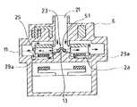
図1は、本発明の遠心式血液ポンプ装置の一実施例の断面図である。図2は、図1に示した本発明の遠心式血液ポンプ装置の平面図である。図3は、図1に示した遠心式血液ポンプ装置の内部を説明するための説明図である。図4は、図1に示した本発明の血液ポンプ装置の作用を説明するための説明図である。
【0012】
本発明の遠心式血液ポンプ装置1は、血液流入ポート21と血液流出ポート22を有するハウジング6と、ハウジング6内で回転し、回転時の遠心力によって血液を送液するインペラ23を有する遠心式血液ポンプ部2と、インペラ23のための非制御式磁気軸受構成部(インペラ回転トルク発生部)4と、インペラ23のための制御式磁気軸受構成部(インペラ位置制御部)3とを備え、非制御式磁気軸受構成部4および制御式磁気軸受構成部3の作用によりインペラ23は、ハウジング6内の所定位置に保持された状態で回転する。そして、インペラ23は、制御式磁気軸受構成部3の作動停止時であって非制御式磁気軸受構成部4の作動時においても回転可能なものであり、かつこの回転時に、インペラ23は、インペラ23の非制御式磁気軸受構成部側の面とこの面と向かい合うハウジング6の内面(血液ポンプ部形成内面)との間に血液流路29aを形成する。
【0013】
図面を用いて、詳細に説明する。
図1ないし図4に示す実施例の遠心式血液ポンプ装置1は、血液ポンプ部2、インペラ位置制御部3、インペラ回転トルク発生部4を備える。
ハウジング6は、血液流入ポート21と血液流出ポート22を備え、非磁性材料により形成されている。ハウジング6内には、血液流入ポート21および血液流出ポート22と連通する血液流路29が形成されている。このハウジング6内には、インペラ23が収納されている。血液流入ポート21は、ハウジング6の上面の中央付近よりほぼ垂直に突出するように設けられている。血液流出ポート22は、ほぼ円筒状に形成されたハウジング6の側面より接線方向に突出するように設けられている。
【0014】
ハウジング6の血液流路29を形成する部分(ポンプ部ハウジング)の内面であり、具体的には、インペラ23の底面(インペラのインペラ回転トルク発生部側の面)に向かい合う内面2aのほぼ中央(血液流入口に対応する位置)に形成された円柱状に延びる台座部12とこの台座部12の上面より血液流入口側に突出する突出部13を有する。この突出部13は、後述するインペラ23の軸受部51aに受け入れられ、その際には、インペラを軸支する。
【0015】
インペラ23は、円盤状に形成されており、一方の面(血液流入ポート側の面、上面側)に設けられた磁性部材26を備え、他方の面(下面側)に設けられた永久磁石27を備える。磁性部材26は、後述するインペラ位置制御部3の電磁石33によりインペラを血液流入ポート側に吸引するために設けられている。永久磁石27は、後述するインペラ回転トルク発生部4のロータ41に設けられた永久磁石41bによりインペラを血液流入ポートと反対側に吸引し、かつ回転トルクをインペラ回転トルク発生部4より伝達可能にするために設けられている。インペラ位置制御部3およびインペラ回転トルク発生部4により、非接触式磁気軸受が構成され、インペラ23は、相反する方向より引っ張られることにより、ハウジング6内において、ハウジングの内面と接触しない適宜位置にて安定し、非接触状態にてハウジング内を回転する。磁性部材26としては、磁性ステンレスまたはニッケルまたは軟鉄部材等が使用され、ドーナツ板状のものが好ましく、また、等角度間隔にて複数設けてもよい。永久磁石27は、インペラ23の底面付近に等角度間隔にて複数設けてもよく、またドーナツ板状のものに多極着磁を施したものを用いてもよい。
【0016】
インペラ23は、図1および図3に示すように、血液流入ポート21に対応する位置となるインペラの中央付近を貫通し、ハウジング6に形成された台座部12を受け入れ可能な通路24と、通路24の周縁よりその接線方向にかつインペラの周縁まで延びる複数の仕切部25と、通路24の内部に形成され、通路24を閉塞することなく、仕切部25と連続する放射状に延びるアームを有する軸受部51を有する。軸受部51は、図1に示すように、下面が血液流入口側に窪む凹部51aを備えており、この凹部51aは、ハウジング6の内面に形成された突出部13を軸受けする。そして、インペラ23は、隣り合う仕切部25間により形成され、通路24、血液流入ポート21およびハウジング6の血液通路29と連通する複数の血液誘導路28を備える。
【0017】
インペラ位置制御部3およびインペラ回転トルク発生部4の作用により、通常状態では、インペラ23はハウジング6の内面のいずれにも接触することなく、具体的には、上記の凹部51aと突出部13も接触することなく、回転する。もし、何らかの理由により、インペラ位置制御部3の作動が停止した場合には、図4に示すように、インペラ23は、回転トルク発生部4側に移動するが、ハウジング6の突出部13は、インペラ23の軸受部51の凹部51aに受け入れられ、言い換えれば、インペラ23は、軸受部51部分において突出部13に軸支され、その状態で回転する。つまり、インペラ23の軸受部51の凹部51aとハウジングの突出部13によりピボット軸受が構成される。この実施例では、非常時における回転時の摩擦摺動部が、最も周速度が小さい回転中心であるため、摩擦熱による血液破壊や血栓形成が少ない。さらに、インペラはハウジングの突出部13を中心として回転するため、インペラの側面がハウジングの内面に接触することがなく、安定した回転が得られる。
【0018】
また、突出部13の先端までのハウジング内面2aからの高さは、インペラ23の底面(下面)からの軸受部51の凹部51aまでの高さより大きく形成されているため、図4に示すように、ハウジング6の突出部13が、インペラ23の軸受部51にてインペラを軸支する状態においても、インペラの下面とハウジング内面間に血液流路29aを確保し、インペラの下面とハウジング内面間での血液滞留およびそれに起因する血栓の発生を防止する。
【0019】
血液の流れは、図1に示す通常状態および図4に示す位置制御部非作動時においても、図4に矢印で示すように、血液流入口21から流入した血液は通路24を経てインペラ内の血液誘導路28を通過し、インペラの側面とハウジング内面間に形成された血液流路29を経て流出口22から流出する。この時インペラの血液誘導路28を通過した血液の一部はインペラ23の下面とハウジング内面2a間に流入し逆流して、インペラ23の通路24の下部より通路内に流入する血液流路29aが形成される。これにより、インペラ23の下面とハウジング内面2a間での血液滞留の発生を防止している。
【0020】
インペラ位置制御部3は、ハウジング6内に収納された複数の電磁石33と、複数の位置センサ32を有する。インペラ位置制御部3の複数(3つ)の電磁石33および複数(3つ)の位置センサ32は、それぞれ等角度間隔にて設けられており、電磁石33と位置センサ32も等角度間隔にて設けられている。電磁石33は、鉄心33aとコイル33bからなる。電磁石33は、この実施例では、図2に示すように、3個設けられている。電磁石は、3個以上、例えば、4つでもよい。3個以上設け、これらの電磁力を後述する位置センサ32の検知結果を用いて調整することにより、インペラの中心軸(z軸)方向の力を釣り合わせ、かつ中心軸(z軸)に直交するx軸およびy軸まわりのモーメントを0にすることができる。
【0021】
位置センサ32は、電磁石33と磁性部材26との隙間の間隔を検知し、この検知出力は、電磁石のコイル33bに与えられる電流を制御する制御部(図示せず)にフィードバックされる。また、インペラ23に重力等による半径方向の力が作用しても、インペラ23の永久磁石27とロータ41の永久磁石41bとの間の磁束の剪断力および電磁石33と磁性部材26との間の磁束の剪断力が作用するため、インペラ23はハウジング6の中心に保持される。
【0022】
インペラ回転トルク発生部4は、ロータ41とロータを回転させるためのモータ42(内部構造を省略する)からなる。ロータ41は、回転板41aと回転板の一方の面(血液ポンプ側の面)に設けられた複数の永久磁石41bからなる。ロータ41の中心は、モータ42の回転軸に固定されている。永久磁石41bは、インペラ23の永久磁石の配置形態(数および配置位置)に対応するように、複数かつ等角度ごとに設けられている。
インペラ回転トルク発生部としては、上述のロータおよびモータを備えるものに限られず、例えば、インペラの永久磁石を吸引し、かつ回転駆動させるための複数のステーターコイルからなるもの(いわゆる、ローターマグネット)でもよい。
【0023】
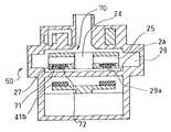
次に、図5、図6および図10に示す実施例の遠心式血液ポンプ装置10について説明する。
この実施例の血液ポンプ装置10の基本構成は、図1ないし図4に示し説明した血液ポンプ装置1と同じであり、相違は、インペラの形状のみである。
インペラ30は、図5および図6に示すように、血液流入ポート21に対応する位置となるインペラの中央付近に形成され、ハウジング6に形成された台座部12を受け入れ可能な通路24と、通路24の周縁よりその接線方向にかつ湾曲してインペラの周縁まで延びる複数の仕切部25と、通路24の内部に形成され、通路24を閉塞することなく、仕切部25と連続する放射状に延びるアームを有する軸受部55を有する。軸受部55は、図6に示すように、中央に小径かつ台座部12に形成された突出部13の先端部の外径より若干大きい内径を有する貫通口55aを備える。この貫通口55aの内面により、ハウジング6の内面に形成された突出部13を軸受けする。そして、インペラ30は、隣り合う仕切部25間により形成され、通路24、血液流入ポート21およびハウジング6の血液通路29と連通する複数の血液誘導路28を備える。
【0024】
また、図10に示されているように、インペラ30の軸受部55の貫通口の内面と接触する突出部13の先端部側面までのハウジング内面2aからの高さは、インペラ30の底面(下面)からの軸受部55の貫通口55aまでの高さより大きく形成されているため、図10に示すように、ハウジングの突出部13が、インペラ30の軸受部55にてインペラを軸支する状態においても、インペラの下面とハウジング内面間に血液流路29aを確保し、インペラの下面とハウジング内面間での血液滞留およびそれに起因する血栓の発生を防止する。さらに、インペラの中央部の貫通口により、軸受部55周囲の血液による洗い流し効果が向上し、その付近での血栓形成がより抑制される。さらに、インペラはハウジングの突出部13を中心として回転するため、インペラの側面がハウジングの内面に接触することがなく、安定した回転が得られる。
【0025】
次に、図8、図9および図7に示す実施例の遠心式血液ポンプ装置20について説明する。
この実施例の血液ポンプ装置20の基本構成は、図1ないし図4に示し説明した血液ポンプ装置1と同じであり、相違は、インペラの形状およびハウジングの内面形状のみである。
インペラ40は、図8および図9に示すように、血液流入ポート21に対応する位置となるインペラの中央付近に形成された通路24と、通路24の周縁よりその接線方向にかつ湾曲してインペラの周縁まで延びる複数の仕切部(図示せず)と、隣り合う仕切部間により形成され、通路24、血液流入ポート21およびハウジング6の血液通路29と連通する複数の血液誘導路(図示せず)と、底面(下面)に形成された複数(3つ以上)のリブ45を有する。ハウジング6のインペラの下面と向かい合う内面2aは、台座部などが形成されていない平坦面となっている。
【0026】
この実施例においても、図7に示すように、インペラ40のリブがハウジングの内面2aに接触する状態となっても、インペラの下面とハウジング内面間に血液流路29aを確保するため、両者間での血液滞留およびそれに起因する血栓の発生を防止する。さらに、通常状態において、リブ45が、インペラの下面とハウジング内面間において撹拌作用を発揮するので、両者間における部分的な血液滞留の発生を防止する。
なお、インペラ40にリブ45を設けることなく、ハウジングの内面2a側にインペラ側に突出する複数(3つ以上)のリブを設けてもよい。
【0027】
次に、図11ないし図13に示す実施例の遠心式血液ポンプ装置50について説明する。
この実施例の血液ポンプ装置50の基本構成は、図1ないし図4に示し説明した血液ポンプ装置1と同じであり、相違はインペラの形状およびハウジングの内面形状のみである。
インペラ70は、図11および図12に示すように、血液流入ポート21に対応する位置となるインペラの中央付近に形成された通路24と、通路24の周縁よりその接線方向にかつ湾曲してインペラの周縁まで延びる複数の仕切部(図示せず)と、隣り合う仕切部間により形成され、通路24、血液流入ポート21およびハウジング6の血液通路29と連通する複数の血液誘導路(図示せず)と、底面(下面)に形成された多数の動圧溝71を有する。動圧溝71は、通路24の底面より若干離間した円形部分73の周縁(円周)上に一端を有し、渦状に(湾曲して)、インペラの外周まで、幅が徐々に広がるように延びている。また、多数の動圧溝71はほぼ同じ形状で同じ間隔で形成されている。隣り合う溝71間に形成された部分72は、円形部分73と連続している。
【0028】
この動圧溝を有するため、インペラ位置制御部の非作動時において、図13に示すように、インペラ回転トルク発生部側に吸引されるが、動圧溝71とハウジング内面2a間に形成される動圧軸受け効果により、若干であるが、ハウジング内面より離れ、非接触状態にて回転し、インペラの下面とハウジング内面間に血液流路を確保するため、両者間での血液滞留およびそれに起因する血栓の発生を防止する。さらに、通常状態において、動圧溝が、インペラの下面とハウジング内面間において撹拌作用を発揮するので、両者間における部分的な血液滞留の発生を防止する。
【0029】
次に、図14ないし図16に示す実施例の遠心式血液ポンプ装置80について説明する。
この実施例の血液ポンプ装置80の基本構成は、図1ないし図4に示し説明した血液ポンプ装置1と同じであり、相違はインペラの形状およびハウジングの内面形状のみである。
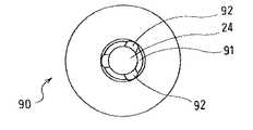
この実施例のものでは、インペラ90は、インペラの底面図である図15およびインペラの断面図である図16に示すように、中央を貫通する通路24と、インペラのインペラ回転トルク発生部側の面の通路端部に形成され外方に向かって拡径するテーパー面部分91を有する。これに対応して、ハウジング内面2aには、インペラ90の前記テーパー面部分91に対応する位置に設けられ、インペラ位置制御部の作動停止時にインペラのテーパー面と接触するテーパー状側面を有する突出部81が設けられている。
【0030】
具体的には、ハウジング6の血液流路29を形成する部分(ポンプ部ハウジング)の内面、つまり、インペラ90の底面(インペラのインペラ回転トルク発生部側の面)に向かい合う内面2aのほぼ中央(血液流入口に対応する位置)に形成された円錐状の突出部81を有する。この突出部の少なくとも先端部は、インペラ90の通路24内に侵入可能な大きさとなっている。
【0031】
インペラ90は、インペラの底面図である図15およびインペラの断面図である図16に示すように、円盤状に形成されており、一方の面(血液流入ポート側の面、上面側)に設けられた磁性部材26を備え、他方の面(下面側)に設けられた永久磁石27を備える。磁性部材26は、後述するインペラ位置制御部3の電磁石33によりインペラを血液流入ポート側に吸引するために設けられている。
さらに、インペラ90は、血液流入ポート21に対応する位置となるインペラの中央付近に形成された通路24と、通路24の周縁よりその接線方向にかつ湾曲してインペラの周縁まで延びる複数の仕切部(図示せず)と、隣り合う仕切部間により形成され、通路24、血液流入ポート21およびハウジング6の血液通路29と連通する複数の血液誘導路(図示せず)を備える。
【0032】
インペラ90は、中央を貫通する通路24の下面側の周縁部には、下方に向かって拡径するテーパー面部分91が形成されており、このテーパーの角度と上記円錐状の突出部のテーパーの角度はほぼ同じに形成されている。また、円錐状の突出部81の底部の外径より、インペラ90のテーパー面部分91の内径の方が小さく形成されている。このため、この実施例では、インペラ位置制御部の作動が停止したとき、インペラの下面とハウジング内面が接触することもなく、円錐状の突出部81とインペラ90のテーパー面部分91がほぼ面接触し、その状態にて回転するため、インペラの側面がハウジングの内面に接触することがなく、安定した回転が得られる。さらに、インペラ90のテーパー面部分91には、溝92が設けられているので、インペラの下面とハウジング内面間に形成された空間に血液が滞留することを防止し、両者間の血液流通を良好にする。
【0033】
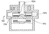
次に、図17ないし図18に示す実施例の遠心式血液ポンプ装置100について説明する。
この実施例の血液ポンプ装置100の基本構成は、図1ないし図4に示し説明した血液ポンプ装置1および図14に示した血液ポンプ装置80と同じであり、相違はインペラの形状およびハウジングの内面形状のみである。
この実施例のものでは、インペラ110は、中央を貫通する通路24と、インペラのインペラ回転トルク発生部側の面の通路端部に形成され外方に向かって拡径するテーパー面部分111aと、インペラの位置制御部側の面の通路端部に形成され外方に向かって拡径するテーパー面部分112aとを有する。
【0034】
これに対応して、ハウジング内面2aには、インペラ110のテーパー面部分111aに対応する位置に設けられ、インペラ位置制御部の作動停止時にインペラのテーパー面と接触するテーパー状側面101aを有する突出部101を有する。さらに、この突出部101は、テーパー状側面より上方に延びる円柱部分101bと、この円柱部分101bよりさらに上方に延びる円錐状部分101cを有する。また、ハウジングの上部側(血液流入ポート側)内面には、インペラ110のテーパー面部分112aに対応する位置に設けられたテーパー状部分102aを有する筒状突出部102を有する。突出部101のテーパー状側面101aの底部の外径より、インペラ110のテーパー面部分の内径の方が小さく形成されている。このため、この実施例では、インペラ位置制御部の作動が停止したとき、インペラの下面とハウジング内面が接触することがなく、突出部101とインペラ110のテーパー面部分がほぼ面接触し、その状態にて回転するため、インペラの側面がハウジングの内面に接触することがなく、安定した回転が得られる。さらに、インペラのテーパー面部分には、図15および図16に示すような溝を設ければ、インペラの下面とハウジング内面間に形成された空間に血液が滞留することを防止し、両者間の血液流通を良好にする。
【0035】
そして、図17に示すように、インペラの通路の内面とハウジングの内面の突出部101の円柱部分101b間のクリアランスg7aは、ハウジングとインペラの側面間のクリアランスg7bより狭くなるように形成されている。このため、半径方向の衝撃力によりインペラが移動しても、周速度の低いインペラの内周部でハウジングと接触することになるため、接触部での損傷をより軽度とすることができる。さらに、この実施例では、インペラ上下の血液ポンプ室の形状がインペラ中心面に対して全く対称な形状となっているため、インペラ上面下面の圧力分布が流量、負荷の変動によらず等しくなり、インペラに軸方向の推力が生じないため、磁気浮上制御用電磁石に対する負荷変動が低減でき、より磁気浮上制御が安定する。
【0036】
【発明の効果】
本発明の遠心式血液ポンプ装置は、血液流入ポートと血液流出ポートを有するハウジングと、該ハウジング内で回転し、回転時の遠心力によって血液を送液するインペラを有する遠心式血液ポンプと、該インペラのための非制御式磁気軸受構成部と、該インペラのための制御式磁気軸受構成部とを備え、該非制御式磁気軸受構成部および前記制御式磁気軸受構成部の作用により前記インペラが前記ハウジング内の所定位置に保持された状態で回転する血液ポンプ装置であり、前記インペラは、前記制御式磁気軸受構成部の作動停止時であって前記非制御式磁気軸受構成部の作動時においても回転可能なものであり、かつこの回転時に、前記インペラの前記非制御式磁気軸受構成部側の面(下面)と該面と向かい合う前記ハウジング内面との間に血液流路を形成する。このため、制御式磁気軸受構成部の非作動時においても非制御式磁気軸受構成部によりインペラが回転する、いわゆるフェールセーフ機構を備え、かつ、フェールセーフ機構によるインペラ回転時においても、インペラの下面とハウジング内面間での血液滞留が防止され、血栓の発生が少ない。
【0037】
本発明の遠心式血液ポンプ装置は、血液流入ポートと血液流出ポートを有するハウジングと、該ハウジング内で回転し、回転時の遠心力によって血液を送液するインペラを有する遠心式血液ポンプと、該インペラのための非制御式磁気軸受構成部と、該インペラのための制御式磁気軸受構成部とを備え、該非制御式磁気軸受構成部および前記制御式磁気軸受構成部の作用により前記インペラが前記ハウジング内の所定位置に保持された状態で回転する血液ポンプ装置であり、前記インペラは、前記制御式磁気軸受構成部の作動停止時であって前記非制御式磁気軸受構成部の作動時においても回転可能なものであり、該インペラは、中央を貫通する通路と、該インペラの前記非制御式磁気軸受構成部側の面の前記通路端部に形成され外方に向かって拡径するテーパー面を有し、前記ハウジング内面には、前記インペラの前記通路に対応する位置に設けられ、前記制御式磁気軸受構成部の作動停止時に前記インペラのテーパー面と接触するテーパー状側面を有する突出部を有する。このため、制御式磁気軸受構成部の非作動時においても非制御式磁気軸受構成部によりインペラが回転する、いわゆるフェールセーフ機構を備え、かつ、フェールセーフ機構によるインペラ回転時には、インペラの下面とハウジング内面が接触することがなく、インペラのテーパー面とハウジングの突出部のテーパー状側面とがほぼ面接触し、その状態にて回転するため、インペラの側面がハウジングの内面に接触することがなく、安定した回転が得られる。
【図面の簡単な説明】
【図1】 図1は、本発明の遠心式血液ポンプ装置の一実施例の断面図である。
【図2】 図2は、図1に示した本発明の遠心式血液ポンプ装置の平面図である。
【図3】 図3は、図1に示した遠心式血液ポンプ装置の内部を説明するための説明図である。
【図4】 図4は、図1に示した本発明の血液ポンプ装置の作用を説明するための説明図である。
【図5】 図5は、本発明の遠心式血液ポンプ装置の他の実施例の断面図である。
【図6】 図6は、図5に示した本発明の遠心式血液ポンプ装置に使用されるインペラの平面図である。
【図7】 図7は、図8に示した本発明の血液ポンプ装置の作用を説明するための説明図である。
【図8】 図8は、本発明の遠心式血液ポンプ装置の他の実施例の断面図である。
【図9】 図9は、図8に示した本発明の遠心式血液ポンプ装置に使用されるインペラの底面図である。
【図10】 図10は、図5に示した本発明の血液ポンプ装置の作用を説明するための説明図である。
【図11】 図11は、本発明の遠心式血液ポンプ装置の他の実施例の断面図である。
【図12】 図12は、図11に示した本発明の遠心式血液ポンプ装置に使用されるインペラの底面図である。
【図13】 図13は、図11に示した本発明の血液ポンプ装置の作用を説明するための説明図である。
【図14】 図14は、本発明の遠心式血液ポンプ装置の他の実施例の断面図である。
【図15】 図15は、図14に示した本発明の遠心式血液ポンプ装置に使用されるインペラの底面図である。
【図16】 図16は、図15のA−A線にて切断したインペラの断面図である。
【図17】 図17は、本発明の遠心式血液ポンプ装置の他の実施例の断面図である。
【図18】 図18は、図17に示した本発明の血液ポンプ装置の作用を説明するための説明図である。
【符号の説明】
1 遠心式血液ポンプ装置
2 遠心式血液ポンプ
3 制御式磁気軸受構成部(インペラ位置制御部)
4 非制御式磁気軸受構成部(インペラ回転トルク発生部)
21 血液流入ポート
22 血液流出ポート
23 インペラ
26 磁性部材
27 インペラの永久磁石
29 血液流路
29a 血液流路
33 電磁石
41 ロータ
41b ロータの永久磁石[0001]
BACKGROUND OF THE INVENTION
The present invention relates to a magnetic bearing type centrifugal pump device for transporting blood.
[0002]
[Prior art]
As a magnetic bearing type pump device for transporting biological fluids such as blood and plasma, those disclosed in Japanese Patent Publication No. 3-70500 and Japanese Patent Publication No. 7-51955 are known. These are magnetic bearing type centrifugal or axial flow turbo pumps that rotate in a state where the impeller is not in contact with other components at all by controlling the position of a magnetic member constituting the impeller by a magnetic force such as an electromagnet. This blood pump device includes an impeller position control unit (in other words, a controlled magnetic bearing component) including an electromagnet, a position sensor, and the like, an impeller rotational torque generating unit (in other words, an uncontrolled magnetic bearing component), and a housing. .
[0003]
[Problems to be solved by the invention]
The most important issues to be considered in transporting blood are to prevent destruction of important components such as red blood cells and platelets, and to prevent blood from coagulating due to foreign body reactions and the like. Magnetic bearing blood pumps that do not have a friction interface on the blood contact surface are very advantageous in this respect, and are therefore promising as long-term use blood pumps on a monthly basis. However, in such a magnetic bearing pump, when the magnetic bearing component does not function, specifically, when the impeller position control unit (in other words, the controlled magnetic bearing component) does not operate, the impeller Is attracted to the impeller rotational torque generating part (in other words, the non-controllable magnetic bearing constituent part), it is conceivable that the impeller does not rotate due to the magnetic attraction force of both, and the pump function is stopped. When the pump function stops, the blood inside the blood clots. For this reason, it is preferable to provide a so-called fail-safe mechanism that can maintain rotation and prevent blood coagulation until the blood pump is replaced even when the impeller position control is stopped.
[0004]
Furthermore, it is preferable that thrombus generation in the blood pump is small even when the impeller is rotated by such a fail-safe mechanism. In particular, blood between the impeller and the inner surface of the blood pump housing on the side of the impeller rotation torque generator is preferably blood. Since stagnation is likely to occur, it is necessary to be able to suppress blood stagnation in this portion.
[0005]
Therefore, the first problem of the present invention is that the impeller can be rotated by the impeller rotation torque generating unit (non-control type magnetic bearing component) even when the impeller position control unit (control type magnetic bearing component) is not operated. A centrifugal blood pump device that includes a so-called fail-safe mechanism and generates less thrombus inside the blood pump even when the impeller is rotated by the fail-safe mechanism.
[0006]
In addition, the second problem of the present invention is that the impeller can be rotated by the impeller rotational torque generating unit (non-control type magnetic bearing component) even when the impeller position control unit (control type magnetic bearing component) is not in operation. A centrifugal blood pump device having a so-called fail-safe mechanism and having good rotation of the impeller during impeller rotation by the fail-safe mechanism is provided.
[0007]
[Means for Solving the Problems]
What solves the first problem is:A housing having a blood inflow port and a blood outflow port, a centrifugal blood pump having an impeller that rotates in the housing and feeds blood by centrifugal force at the time of rotation, and a non-controllable magnetic bearing configuration for the impeller And a controlled magnetic bearing component for the impeller, and the impeller is held at a predetermined position in the housing by the action of the non-controllable magnetic bearing component and the controlled magnetic bearing component The impeller is rotatable when the operation of the control type magnetic bearing component is stopped and when the non-control type magnetic bearing component is operated, and the rotation Sometimes, a blood flow path is formed between a surface of the impeller on the non-controllable magnetic bearing component side and the inner surface of the housing facing the surface. The la has a small-diameter through-hole provided at substantially the center of the surface on the non-control type magnetic bearing component side, and is provided on the inner surface of the housing at a position corresponding to the through-hole of the impeller, An inner surface of the housing having a protrusion for entering the through-hole and pivotally supporting the impeller at the through-hole portion, and further up to a side surface of the protruding portion that contacts the inner surface of the through-hole of the impeller The height from is formed larger than the height from the bottom surface of the impeller to the through hole. It is a centrifugal blood pump device.
[0008]
The impeller includes, for example, a magnetic member provided on one surface side and a permanent magnet provided on the other surface side. The control-type magnetic bearing component preferably includes a fixed electromagnet for attracting the magnetic member of the impeller and a position sensor for detecting the position of the magnetic member of the impeller. Furthermore, the non-control type magnetic bearing component includes, for example, a rotor including a permanent magnet for attracting the permanent magnet of the impeller, and a motor that rotates the rotor. Moreover, the said non-control type magnetic bearing structure part is provided with the several stator coil for rotationally driving, for example, attracting | sucking the permanent magnet of the said impeller.
The impeller includes a passage formed near the center of the impeller, and a bearing portion formed inside the passage so as not to close the passage, and the bearing portion includes the protruding portion. The through hole having an inner diameter slightly larger than the outer diameter of the front end of the housing is provided, and the protrusion formed on the inner surface of the housing is supported by the inner surface of the through hole.
[0009]
Moreover, what solves said 2nd subject is the centrifugal blood which has the impeller which rotates in the housing which has a blood inflow port and a blood outflow port, and rotates blood in this housing and sends blood with the centrifugal force at the time of rotation A pump, a non-controllable magnetic bearing component for the impeller, and a controllable magnetic bearing component for the impeller, by the action of the non-controllable magnetic bearing component and the controllable magnetic bearing component A blood pump device that rotates in a state where the impeller is held at a predetermined position in the housing, and the impeller is at a time when the operation of the control type magnetic bearing component is stopped and the non-control type magnetic bearing component The impeller is rotatable at the time of operation, and the impeller is formed at the end of the passage on the non-controllable magnetic bearing component side surface of the impeller and on the outer side. The inner surface of the housing is provided at a position corresponding to the passage of the impeller, and comes into contact with the tapered surface of the impeller when the operation of the control type magnetic bearing component is stopped. Protrusions with tapered sidesFurthermore, the inner diameter of the tapered surface portion of the impeller is smaller than the outer diameter of the bottom portion of the tapered side surface of the protruding portion. It is a centrifugal blood pump device.
[0010]
When the impeller is rotated when the operation of the control type magnetic bearing component is stopped and when the non-control type magnetic bearing component is operated, the impeller is a surface of the impeller on the non-control type magnetic bearing component side. It is preferable that a blood flow path be formed between the housing and the housing inner surface facing the surface. Further, the tapered surface of the impeller or the projecting portion of the inner surface of the housing has the above-described control-type magnetic bearing component at the time of operation stop and the non-controllable magnetic bearing component at the time of impeller rotation, It is preferable that a groove for improving blood flow between the impeller and the housing is formed.
[0011]
DETAILED DESCRIPTION OF THE INVENTION
The centrifugal blood pump device of the present invention will be described with reference to the embodiments shown in the drawings.
FIG. 1 is a cross-sectional view of an embodiment of a centrifugal blood pump device of the present invention. FIG. 2 is a plan view of the centrifugal blood pump apparatus of the present invention shown in FIG. FIG. 3 is an explanatory diagram for explaining the inside of the centrifugal blood pump apparatus shown in FIG. 1. FIG. 4 is an explanatory diagram for explaining the operation of the blood pump device of the present invention shown in FIG.
[0012]
The centrifugal
[0013]
This will be described in detail with reference to the drawings.
The centrifugal
The
[0014]
It is the inner surface of the portion (pump portion housing) that forms the
[0015]
The
[0016]
As shown in FIGS. 1 and 3, the
[0017]
Due to the action of the impeller
[0018]
Also,Protrusion Since the height from the housing
[0019]
In the normal state shown in FIG. 1 and when the position control unit shown in FIG. 4 is not in operation, the blood flows from the
[0020]
The impeller
[0021]
The
[0022]
The impeller
The impeller rotational torque generating unit is not limited to the one provided with the above-described rotor and motor, and may be, for example, one composed of a plurality of stator coils (so-called rotor magnets) for attracting and rotating the permanent magnet of the impeller. Good.
[0023]
Next, the centrifugal
The basic configuration of the
As shown in FIGS. 5 and 6, the
[0024]
Also,As shown in FIG. 10, the protruding portion that contacts the inner surface of the through hole of the bearing
[0025]
Next, the centrifugal
The basic configuration of the
As shown in FIGS. 8 and 9, the
[0026]
Also in this embodiment, as shown in FIG. 7, even if the rib of the
Instead of providing the
[0027]
Next, the centrifugal
The basic configuration of the
As shown in FIGS. 11 and 12, the
[0028]
Since this dynamic pressure groove is provided, when the impeller position control unit is not in operation, as shown in FIG. 13, it is attracted to the impeller rotational torque generating unit side, but is formed between the
[0029]
Next, the centrifugal
The basic configuration of the
In this embodiment, as shown in FIG. 15 which is a bottom view of the impeller and FIG. 16 which is a cross-sectional view of the impeller, the
[0030]
Specifically, the inner surface of the portion of the
[0031]
As shown in FIG. 15 which is a bottom view of the impeller and FIG. 16 which is a cross-sectional view of the impeller, the
Further, the
[0032]
In the
[0033]
Next, the centrifugal
The basic configuration of the
In this embodiment, the
[0034]
Correspondingly, the housing
[0035]
As shown in FIG. 17, the clearance g7a between the inner surface of the impeller passage and the
[0036]
【The invention's effect】
The centrifugal blood pump device of the present invention includes a housing having a blood inflow port and a blood outflow port, a centrifugal blood pump having an impeller that rotates in the housing and feeds blood by centrifugal force during rotation, A non-controllable magnetic bearing component for the impeller and a controllable magnetic bearing component for the impeller, and the impeller is moved by the action of the non-controllable magnetic bearing component and the controllable magnetic bearing component. A blood pump device that rotates while being held at a predetermined position in a housing, wherein the impeller is at a time when the operation of the control type magnetic bearing component is stopped and also when the non-control type magnetic bearing component is operated. Between the surface (lower surface) of the impeller on the side of the non-controllable magnetic bearing component and the inner surface of the housing facing the surface during rotation. Forming a blood channel. For this reason, the impeller has a so-called fail-safe mechanism in which the impeller is rotated by the non-controllable magnetic bearing component even when the control-type magnetic bearing component is not in operation, and the lower surface of the impeller also during the impeller rotation by the fail-safe mechanism And blood accumulation between the inner surfaces of the housing is prevented, and thrombus generation is small.
[0037]
The centrifugal blood pump device of the present invention includes a housing having a blood inflow port and a blood outflow port, a centrifugal blood pump having an impeller that rotates in the housing and feeds blood by centrifugal force during rotation, A non-controllable magnetic bearing component for the impeller and a controllable magnetic bearing component for the impeller, and the impeller is moved by the action of the non-controllable magnetic bearing component and the controllable magnetic bearing component. A blood pump device that rotates while being held at a predetermined position in a housing, wherein the impeller is at a time when the operation of the control type magnetic bearing component is stopped and also when the non-control type magnetic bearing component is operated. The impeller is formed at a passage through the center and an end of the passage on a surface of the impeller on the non-controllable magnetic bearing component side, and is directed outward. The inner surface of the housing is provided at a position corresponding to the passage of the impeller, and comes into contact with the tapered surface of the impeller when the operation of the control type magnetic bearing component is stopped. A protrusion having a side surface; For this reason, the impeller has a so-called fail-safe mechanism in which the impeller is rotated by the non-controllable magnetic bearing component even when the control-type magnetic bearing component is not in operation, and when the impeller is rotated by the fail-safe mechanism, the lower surface of the impeller and the housing The inner surface is not in contact, and the tapered surface of the impeller and the tapered side surface of the protruding portion of the housing are substantially in surface contact with each other, so that the side surface of the impeller does not contact the inner surface of the housing. Stable rotation can be obtained.
[Brief description of the drawings]
FIG. 1 is a cross-sectional view of an embodiment of a centrifugal blood pump apparatus according to the present invention.
FIG. 2 is a plan view of the centrifugal blood pump device of the present invention shown in FIG.
FIG. 3 is an explanatory diagram for explaining the inside of the centrifugal blood pump device shown in FIG. 1;
FIG. 4 is an explanatory diagram for explaining the operation of the blood pump device of the present invention shown in FIG. 1;
FIG. 5 is a cross-sectional view of another embodiment of the centrifugal blood pump device of the present invention.
6 is a plan view of an impeller used in the centrifugal blood pump device of the present invention shown in FIG. 5. FIG.
FIG. 7 is an explanatory diagram for explaining the operation of the blood pump device of the present invention shown in FIG. 8;
FIG. 8 is a cross-sectional view of another embodiment of the centrifugal blood pump device of the present invention.
FIG. 9 is a bottom view of an impeller used in the centrifugal blood pump apparatus of the present invention shown in FIG.
FIG. 10 is an explanatory diagram for explaining the operation of the blood pump device of the present invention shown in FIG.
FIG. 11 is a cross-sectional view of another embodiment of the centrifugal blood pump device of the present invention.
12 is a bottom view of the impeller used in the centrifugal blood pump device of the present invention shown in FIG. 11. FIG.
FIG. 13 is an explanatory diagram for explaining the operation of the blood pump device of the present invention shown in FIG.
FIG. 14 is a cross-sectional view of another embodiment of the centrifugal blood pump device of the present invention.
FIG. 15 is a bottom view of the impeller used in the centrifugal blood pump apparatus of the present invention shown in FIG.
FIG. 16 is a cross-sectional view of the impeller cut along line AA in FIG. 15;
FIG. 17 is a cross-sectional view of another embodiment of the centrifugal blood pump device of the present invention.
FIG. 18 is an explanatory diagram for explaining the operation of the blood pump device of the present invention shown in FIG.
[Explanation of symbols]
1 Centrifugal blood pump device
2 Centrifugal blood pump
3. Control type magnetic bearing component (impeller position controller)
4 Non-control type magnetic bearing component (impeller rotational torque generator)
21 Blood inflow port
22 Blood outflow port
23 Impeller
26 Magnetic members
27 Permanent magnet of impeller
29 Blood channel
29a Blood channel
33 Electromagnet
41 rotor
41b Permanent magnet of rotor
Claims (13)
Translated fromJapanesePriority Applications (2)
| Application Number | Priority Date | Filing Date | Title |
|---|---|---|---|
| JP03885096AJP3853865B2 (en) | 1996-01-31 | 1996-01-31 | Centrifugal blood pump device |
| US08/791,560US5947703A (en) | 1996-01-31 | 1997-01-31 | Centrifugal blood pump assembly |
Applications Claiming Priority (1)
| Application Number | Priority Date | Filing Date | Title |
|---|---|---|---|
| JP03885096AJP3853865B2 (en) | 1996-01-31 | 1996-01-31 | Centrifugal blood pump device |
Publications (2)
| Publication Number | Publication Date |
|---|---|
| JPH09206372A JPH09206372A (en) | 1997-08-12 |
| JP3853865B2true JP3853865B2 (en) | 2006-12-06 |
Family
ID=12536680
Family Applications (1)
| Application Number | Title | Priority Date | Filing Date |
|---|---|---|---|
| JP03885096AExpired - LifetimeJP3853865B2 (en) | 1996-01-31 | 1996-01-31 | Centrifugal blood pump device |
Country Status (1)
| Country | Link |
|---|---|
| JP (1) | JP3853865B2 (en) |
Families Citing this family (9)
| Publication number | Priority date | Publication date | Assignee | Title |
|---|---|---|---|---|
| JP3689567B2 (en)* | 1998-09-29 | 2005-08-31 | 京セラ株式会社 | Centrifugal blood pump |
| JP2001178816A (en)* | 1999-12-27 | 2001-07-03 | Sofutoronikusu Kk | Intracorporeally implanting type artificial heart |
| JP4106484B2 (en)* | 2002-01-23 | 2008-06-25 | 独立行政法人産業技術総合研究所 | Magnetic levitation pump with hydrodynamic bearing |
| JP2003269378A (en) | 2002-03-14 | 2003-09-25 | San Medical Gijutsu Kenkyusho:Kk | Centrifugal pump |
| EP1598087B1 (en) | 2004-03-24 | 2010-02-03 | Terumo Kabushiki Kaisha | blood pump with hydrodynamic bearing |
| JP4787726B2 (en) | 2006-11-28 | 2011-10-05 | テルモ株式会社 | Sensorless magnetic bearing blood pump device |
| JP5623203B2 (en)* | 2010-09-08 | 2014-11-12 | テルモ株式会社 | Centrifugal blood pump and centrifugal blood pump device |
| EP2719403B1 (en)* | 2012-10-12 | 2016-09-28 | Abiomed Europe GmbH | Centrifugal blood pump |
| JP6533047B2 (en) | 2014-09-26 | 2019-06-19 | 株式会社ハイレックスコーポレーション | Medical centrifugal pump and artificially assisted heart having the medical centrifugal pump |
- 1996
- 1996-01-31JPJP03885096Apatent/JP3853865B2/ennot_activeExpired - Lifetime
Also Published As
| Publication number | Publication date |
|---|---|
| JPH09206372A (en) | 1997-08-12 |
Similar Documents
| Publication | Publication Date | Title |
|---|---|---|
| US11654273B2 (en) | Blood pump supported by passive magnetic forces | |
| JP3594315B2 (en) | Centrifugal pump for blood and other shear-sensitive liquids | |
| US11672968B2 (en) | Blood-immersed bearing system for a blood pump | |
| JPH09313600A (en) | Centrifugal liquid pump | |
| US6206659B1 (en) | Magnetically driven rotor for blood pump | |
| US4609332A (en) | Turbo-molecular pump | |
| US5470208A (en) | Fluid pump with magnetically levitated impeller | |
| JP4472610B2 (en) | Centrifugal blood pump device | |
| US6846168B2 (en) | Pump with an electrodynamically supported impeller and a hydrodynamic bearing between the impeller and the stator | |
| US6840735B2 (en) | Centrifugal fluid pump apparatus | |
| US5924848A (en) | Blood pump having radial vanes with enclosed magnetic drive components | |
| US20050008496A1 (en) | Centrifugal fluid pump apparatus | |
| JP4340178B2 (en) | Centrifugal blood pump device | |
| KR20150068456A (en) | Centrifugal blood pump | |
| JP3853865B2 (en) | Centrifugal blood pump device | |
| JP2006525460A (en) | Fluid pump | |
| WO2007032249A1 (en) | Artificial heart pump | |
| CN112524038A (en) | Centrifugal pump and pump casing | |
| JP2008121686A (en) | Artificial heart pump | |
| JP2008088986A (en) | Artificial heart pump | |
| US7598643B2 (en) | Motor with electrodynamically and hydrodynamically supported rotor | |
| EP1003970B1 (en) | Improved rotor for blood pump | |
| EP3854447B1 (en) | Centrifugal blood pump | |
| CN114042241B (en) | Magnetic suspension pump | |
| JP4485379B2 (en) | Bearing and blood pump |
Legal Events
| Date | Code | Title | Description |
|---|---|---|---|
| A977 | Report on retrieval | Free format text:JAPANESE INTERMEDIATE CODE: A971007 Effective date:20050222 | |
| A131 | Notification of reasons for refusal | Free format text:JAPANESE INTERMEDIATE CODE: A131 Effective date:20050322 | |
| A521 | Request for written amendment filed | Free format text:JAPANESE INTERMEDIATE CODE: A523 Effective date:20050523 | |
| A131 | Notification of reasons for refusal | Free format text:JAPANESE INTERMEDIATE CODE: A131 Effective date:20050913 | |
| A521 | Request for written amendment filed | Free format text:JAPANESE INTERMEDIATE CODE: A523 Effective date:20051110 | |
| TRDD | Decision of grant or rejection written | ||
| A01 | Written decision to grant a patent or to grant a registration (utility model) | Free format text:JAPANESE INTERMEDIATE CODE: A01 Effective date:20060822 | |
| A61 | First payment of annual fees (during grant procedure) | Free format text:JAPANESE INTERMEDIATE CODE: A61 Effective date:20060907 | |
| R150 | Certificate of patent or registration of utility model | Free format text:JAPANESE INTERMEDIATE CODE: R150 | |
| FPAY | Renewal fee payment (event date is renewal date of database) | Free format text:PAYMENT UNTIL: 20090915 Year of fee payment:3 | |
| FPAY | Renewal fee payment (event date is renewal date of database) | Free format text:PAYMENT UNTIL: 20100915 Year of fee payment:4 | |
| FPAY | Renewal fee payment (event date is renewal date of database) | Free format text:PAYMENT UNTIL: 20100915 Year of fee payment:4 | |
| FPAY | Renewal fee payment (event date is renewal date of database) | Free format text:PAYMENT UNTIL: 20110915 Year of fee payment:5 | |
| FPAY | Renewal fee payment (event date is renewal date of database) | Free format text:PAYMENT UNTIL: 20120915 Year of fee payment:6 | |
| FPAY | Renewal fee payment (event date is renewal date of database) | Free format text:PAYMENT UNTIL: 20130915 Year of fee payment:7 | |
| R250 | Receipt of annual fees | Free format text:JAPANESE INTERMEDIATE CODE: R250 | |
| R250 | Receipt of annual fees | Free format text:JAPANESE INTERMEDIATE CODE: R250 | |
| R250 | Receipt of annual fees | Free format text:JAPANESE INTERMEDIATE CODE: R250 | |
| EXPY | Cancellation because of completion of term |