JP3852073B2 - Optical head track actuator device - Google Patents
Optical head track actuator deviceDownload PDFInfo
- Publication number
- JP3852073B2 JP3852073B2JP2001328014AJP2001328014AJP3852073B2JP 3852073 B2JP3852073 B2JP 3852073B2JP 2001328014 AJP2001328014 AJP 2001328014AJP 2001328014 AJP2001328014 AJP 2001328014AJP 3852073 B2JP3852073 B2JP 3852073B2
- Authority
- JP
- Japan
- Prior art keywords
- mirror
- mirror holder
- leaf spring
- coil
- fixed base
- Prior art date
- Legal status (The legal status is an assumption and is not a legal conclusion. Google has not performed a legal analysis and makes no representation as to the accuracy of the status listed.)
- Expired - Fee Related
Links
Images


Landscapes
- Optical Recording Or Reproduction (AREA)
Description
Translated fromJapanese【0001】
【発明の属する技術分野】
本発明は、光ディスク、光磁気ディスクなどの光学式記録媒体(以下、単に光ディスクという)に信号を記録し、または同光ディスクに記録された信号を再生若しくは消去する光ヘッドのトラックアクチュエータ装置に関する。
【0002】
【従来の技術】
従来、この種の装置としては、例えば特開平4−255919号公報、特開平4−255923号公報および特開平5−128561号公報に示されているように、対物レンズへのレーザ光および対物レンズからのレーザ光を反射するミラー(ガルバノミラー)を、ミラーの反射面と対物レンズの像側焦平面とが交差する交線を中心軸に回転させるようにして、トラッキング制御に伴う反射光の光軸シフトが生じないようにしている。
【0003】
特開平4−255919号公報に示されたアクチュエータは、圧電素子の変位を拡大率の異なる一対のアームを介して前記中心軸からの距離が異なるミラーの両端部に伝達して、ミラーを前記中心軸回りに回転させるようにしている。特開平4−255923号公報に示されたアクチュエータは、前記中心軸からの距離が異なる固定ベース上の2位置に大きさの異なる2種類のばねを介してミラーを弾性的に支持させておいて、コイルおよび磁石による電磁力により、ミラーを前記中心軸回りに回転させるようにしている。特開平5−128561号公報に示されたアクチュエータは、一端を固定ベースに固定した平行板ばね機構の先端に一枚の板ばねを組付けるとともに、この一枚の板ばねの先端にミラーを組付けて、ミラーを平行板ばねおよび一枚の板ばねの垂直方向にアクチュエータによって駆動して、ミラーを前記中心軸回りに回転させるようにしている。
【0004】
【発明が解決しようとする課題】
しかし、上記の従来技術においては、ミラーを前記中心軸回りに高精度かつ少ないばらつきで回転させることができない。すなわち、特開平4−255919号公報に示されたアクチュエータの場合、ミラーを前記中心軸回りに正確に回転させるための一対のアームによる拡大率の設定が難しいとともに、同アームの均一な製造も難しい。特開平4−255923号公報および特開平5−128561号公報に示されたアクチュエータの場合、ミラーを前記中心軸回りに回転させるための2種類のばねにおけるばね定数の設定が難しいとともに、同2種類のばねの均質な製造も難しい。
【0005】
【発明の概要】
本発明は、上記問題を解決するためになされたもので、その目的は、ミラーを所定の中心軸回りに高精度かつ少ないばらつきで回転させることができるようにした光ヘッドのトラックアクチュエータ装置を提供することにある。
【0006】
前記目的を達成するために、本発明の構成上の特徴は、対物レンズへのレーザ光および対物レンズからのレーザ光を反射するミラーを保持するミラーホルダと、ミラーホルダを回転可能に支持する固定ベースと、ミラーの反射面と対物レンズの光軸に垂直な所定平面との交線を含む第1平面内に配置されてミラーホルダを固定ベースに弾性的に支持する第1の板ばねと、第1平面と前記交線にて交差する第2平面内に配置されてミラーホルダを固定ベースに弾性的に支持する第2の板ばねと、ミラーホルダを前記交線を中心軸として固定ベースに対して回転駆動するアクチュエータとを備えたことにある。
【0007】
この場合、前記アクチュエータを、ミラーホルダ側に組み付けられたコイルと、コイルに対向して配置されて固定ベース側に組み付けられた磁石とで構成するとよい。また、前記第1の板ばねをミラーの両側にそれぞれ配置された一対の板ばねで構成するとともに、前記第2の板ばねを第1の板ばねを構成する一対の板ばねに対向する位置にそれぞれ配置された一対の板ばねで構成するとよい。この場合、板ばねとしては、U字状の板ばねを利用できる。さらに、前記コイルを第1および第2のコイルで構成するとともに、前記磁石を第1および第2の磁石で構成し、第1のコイルおよび第1の磁石は第1の板ばねに対して直交する方向にミラーホルダを駆動するようにするとともに、第2のコイルおよび第2の磁石は第2の板ばねに対して直交する方向にミラーホルダを駆動するようにするとよい。
【0008】
上記のように構成した本発明においては、ミラーホルダは、第1平面内に配置された第1の板ばねにより弾性的に支持されるとともに、第2平面内に配置された第2の板ばねにより弾性的に支持されている。そして、アクチュエータが、ミラーホルダを第1平面と第2平面の交線を中心軸として固定ベースに対して回転駆動する。したがって、第1および第2の板ばねにより、ミラーホルダは前記中心軸回りに正確に回転する。また、この場合、第1および第2の板ばねを同一構成にして、同一の弾性力を発揮させればよいので、本発明に係るアクチュエータ装置によれば、ミラーを一つの中心軸回りに高精度かつ少ないばらつきで回転させることができるようになる。
【0009】
【実施の形態】
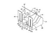
以下、本発明の一実施形態について図面を用いて説明すると、図1は同実施形態に係る光ヘッドのトラックアクチュエータ装置を正面側から見た斜視図であり、図2は同トラックアクチュエータ装置を背面側から見た斜視図である。図3は同トラックアクチュエータ装置の分解斜視図であり、図4は同トラックアクチュエータ装置の断面図である。このトラックアクチュエータ装置は、ミラー10、ミラーホルダ20、固定ベース30、板ばね41〜44およびアクチュエータ50を備えている。
【0010】
ミラー10は、3角柱状に形成したガラス製のプリズムで構成されていて、互いに直交する水平面11および垂直面12(3角柱の2側面に対応)を有するとともに、水平面11および垂直面12に対して45度傾斜させた反射面13を有する。反射面13は、図示しないレーザ光源からの水平進行のレーザ光L1を垂直方向に反射して、レンズホルダ61に固定された対物レンズ60を介して光ディスクDKに導く。また、反射面13は、光ディスクDKから対物レンズ60を介した垂直進行の反射光L2を反射して、図示しないフォトディテクタに導く。
【0011】
ミラーホルダ20は、垂直断面が略台形状になるように透磁率の低い軽金属(例えば、アルミニウム)で一体成形されていて、上面21、正面22、背面23、後方底面24および前方底面25を有するとともに、左右両側を切り欠いて左右対称に構成されている。上面21は水平であって、同上面21にはミラー10が水平面11にて接着固定されている。正面22は上面21に対して45度傾斜していて、ミラー10の反射面と同一平面を構成する。背面23は上面21に対して垂直であって、後方底面24は上面21と平行な水平に形成されている。前方底面25は、後方底面24に対して45度傾斜していて、正面22とは90度で交差している。
【0012】
固定ベース30は、ミラーホルダ20よりも幅広の略直方体状に透磁率の低い軽金属(例えば、アルミニウム)で一体成形されていて、上面中央部を切り欠いて構成されている。正面31および背面32は垂直であって、正面31上部の左右両端には45度傾斜させてミラーホルダ20の正面22と同一平面を形成する傾斜面31a,31bが設けられている。前記切り欠いた上面は、水平な後方上面33および同後方上面33から45度傾斜させて立ち上げた前方上面34からなる。これらの後方上面33および前方上面34は、ミラーホルダ20の後方底面24および前方底面25との間に所定の隙間を設けて平行に構成されている。
【0013】
板ばね41〜44は、それぞれU字型の同一形状に構成されていて、所定の隙間を隔てて同一方向に突出した左右一対の突出辺41a〜44aおよび41b〜44bを有する。板ばね41,42は本発明の第1の板ばねを構成するもので、板ばね41の突出辺41aの先端部は、その裏面にて固定ベース30の傾斜面31aに接着固定されている。板ばね41の突出辺41bの先端部は、その裏面にてミラーホルダ20の正面22の一端部に接着固定されている。板ばね42の突出辺42aの先端部は、その裏面にてミラーホルダ20の正面22の他端部に接着固定されている。板ばね42の突出辺42bの先端部は、その裏面にて固定ベース30の傾斜面31bに接着固定されている。
【0014】
板ばね43,44は本発明の第2の板ばねを構成するもので、板ばね43の突出辺43aの先端部は、その表面にて固定ベース30の背面32の一端部に接着固定されている。板ばね43の突出辺43bの先端部は、その表面にてミラーホルダ20の背面23の一端部に接着固定されている。板ばね44の突出辺44aの先端部は、その表面にてミラーホルダ20の背面23の他端部に接着固定されている。板ばね44の突出辺44bの先端部は、その表面にて固定ベース30の背面32の他端部に接着固定されている。
【0015】
これにより、ミラー10およびミラーホルダ20は、板ばね41〜44により、固定ベース30に対して回転変位可能かつ弾性的に支持される。また、この場合におけるミラーホルダ20の回転変位の中心軸Cは、図4に示すように、ミラー10の反射面13(板ばね41,42)の延長面と、ミラーホルダ20の背面23(板ばね43,44)の延長面とが交差する交線となる。そして、本実施形態においては、この中心軸Cは、対物レンズ60の像側焦平面とミラー10の反射面とが交差する交線と一致させてある。なお、対物レンズ60の像側焦平面とは、光ディスクDKの反対側の対物レンズ60の焦点Fを含み、かつ対物レンズ60の光軸に対して垂直な平面である。
【0016】
アクチュエータ50は、第1コイル51および第1永久磁石52からなる第1アクチュエータ50aと、第2コイル53および第1永久磁石54からなる第2アクチュエータ50bとを含む。第1コイル51はミラーホルダ20の左右方向の中央部にて前方底面25に固着され、その一端が通電線51aに接続されるとともに、その他端が第2コイル53に接続されている。第2コイル53はミラーホルダ20の左右方向の中央部にて後方底面24に固着され、その一端が通電線53aに接続されるとともに、その他端が第1コイル51に接続されている。
【0017】
第1および第2永久磁石52,54は、それぞれ高透磁率の金属材料で断面コ字上に形成されたヨーク55,56の各一方の突出辺の内側面にそれぞれ固着されている。ヨーク55は、前記一方の突出辺の外側面にて固定ベース30の前方上面34の正面31側端部に接着固定されていて、第1永久磁石52を第1コイル51に対向させるようにしている。ヨーク56は、前記一方の突出辺の外側面にて固定ベース30の後方上面33の背面32側端部に接着固定されていて、第2永久磁石54を第2コイル53に対向させるようにしている。ヨーク55の他方の突出辺は、ミラーホルダ20の正面22中央部に開口する穴20aに侵入している。ヨーク56の他方の突出辺は、ミラーホルダ20の背面23中央部に開口する穴20bに侵入している。
【0018】
この場合、図5に示すように、永久磁石52による磁力線の向きはコイル51およびミラーホルダ20の前方底面25と直角になるので、コイル51に通電すると、第1アクチュエータ50aによるミラーホルダ20に対する電磁力は板ばね41,42(ミラーホルダ20の正面およびミラー10の反射面)に直角に作用する。一方、永久磁石54による磁力線の向きはコイル53およびミラーホルダ20の後方底面24と直角になるので、コイル53に通電すると、第2アクチュエータ50bによるミラーホルダ20に対する電磁力は板ばね43,44(すなわち、ミラーホルダ20の背面23)に直角に作用する。
【0019】
そして、これらの第1および第2アクチュエータ50a,50bによる電磁力の合成力Fがミラーホルダ20に作用するので、コイル51,53への通電によりミラーホルダ20には回転力が作用する。ここで、第1および第2アクチュエータ50a,50bの各電磁力の大きさを同一に設定すると(各部品共通化のために同一にすることが好ましい)、前記合成力Fは、板ばね41,42と板ばね43,44との中間の2等分線上の位置に作用することになる。なお、ミラーホルダ20の後方底面24と前方底面25の前後方向の各長さ(図4の左右方向の長さ)は等しく、中心軸Cからコイル51,53までの各距離は等しい。したがって、この2等分線上の位置に、ミラーホルダ20およびミラー10の重心が位置するようにミラーホルダ20の形状を設計することが好ましい。
【0020】
次に、前記のように構成した実施形態の動作を説明する。コイル51,53に通電されていない状態では、ミラーホルダ20は、板ばね41〜44の付勢力により、固定ベース30に対して図1,2,4に示す位置(中立位置)にある。
【0021】
一方、コイル51,53に図5に示す方向に電流を流すと、永久磁石52,54との電磁力により、ミラーホルダ20には図5に矢印で示す方向に合成力Fが作用する。したがって、ミラーホルダ20およびミラー10は、板ばね41〜44の付勢力に抗して固定ベース30に対して図5にて右回転方向に中立位置から回転変位する(図5,6(A)参照)。また、逆に、コイル51,53に図5に示す方向と反対方向の電流を流すと、ミラーホルダ20には前記と反対の左回転方向の力が作用する。したがって、この場合には、ミラーホルダ20およびミラー10は、板ばね41〜44の付勢力に抗して固定ベース30に対して中立位置から左回転方向に回転変位する(図6(B)参照)。
【0022】
そして、前記ミラーホルダ20に作用する回転力すなわちミラー10の反射面13の中立位置から左右回転方向への回転変位量は、コイル51,53に流れる電流の大きさに比例する。したがって、コイル51,53に流す電流の向きおよび大きさを制御することにより、レーザ光の光軸を任意の量だけ中立位置から前後にずらすことができる。その結果、これによれば、ミラー10の回転によるトラックサーボ制御が実現される。
【0023】
前記のように構成されるとともに作動するトラックアクチュエータ装置においては、ミラーホルダ20は、中心軸Cを含むミラーホルダ20の正面22(ミラー10の反射面13)内に配置された板ばね41,42により弾性的に支持されるとともに、中心軸Cを含むミラーホルダ20の背面23内に配置された板ばね43,44により弾性的に支持されている。そして、アクチュエータ50は、ミラーホルダ20およびミラー10を中心軸C回りに固定ベース30に対して回転駆動する。したがって、これらの板ばね41〜44により、ミラーホルダ20が中心軸C回りに正確に回転する。また、この場合、板ばね41〜44を同一構成にして、同一の弾性力を発揮させればよいので、このトラックアクチュエータ装置によれば、ミラー10を所定の中心軸回りに高精度かつ少ないばらつきで回転させることができるようになる。
【0024】
なお、上記実施形態においては、ミラー10およびミラーホルダ20の回転中心軸Cを、像側焦平面とミラー10の反射面13との交線に設定するようにしたが、この中心軸Cは必ずしも厳密に前記位置にある必要はない。すなわち、トラッキング制御に伴う反射光の光軸シフトが許容される範囲内であれば、焦点Fよりも対物レンズ60に近い位置または遠い位置を含む対物レンズ60の光軸に直交する平面と、ミラー13の反射面13との交線が、ミラー10およびミラーホルダ20の回転中心軸C(すなわち、基準状態にて板ばね41,42を含む平面と板ばね43,44を含む平面との交線)となるようにしてもよい。例えば、対物レンズ60への入射光をなるべく多くするために、レンズホルダ61のミラー10側の開口面とミラー10の反射面13との交線を、前記中心軸Cとすることも考えられる。
【図面の簡単な説明】
【図1】 本発明の一実施形態を示す光ヘッドのトラックアクチュエータ装置を正面側から見た斜視図である。
【図2】 同トラックアクチュエータ装置を背面側から見た斜視図である。
【図3】 同トラックアクチュエータの分解斜視図である。
【図4】 同トラックアクチュエータ装置の断面図である。
【図5】 ミラーおよびミラーホルダを右回転方向に回転させた状態を示すトラックアクチュエータの断面図である。
【図6】 (A)はミラーおよびミラーホルダを右回転方向に回転させた状態を示すトラックアクチュエータの斜視図であり、(B)はミラーおよびミラーホルダを左回転方向に回転させた状態を示すトラックアクチュエータの斜視図である。
【符号の説明】
10…ミラー、13…反射面、20…ミラーホルダ、30…固定ベース、41〜44…板ばね、50…アクチュエータ、50a…第1アクチュエータ、50b…第2アクチュエータ、51,53…コイル、52,54…永久磁石、55,56…ヨーク、60…対物レンズ、DK…光ディスク。[0001]
BACKGROUND OF THE INVENTION
The present invention relates to a track actuator device for an optical head that records a signal on an optical recording medium (hereinafter simply referred to as an optical disk) such as an optical disk or a magneto-optical disk, or reproduces or erases a signal recorded on the optical disk.
[0002]
[Prior art]
Conventionally, as this type of apparatus, as shown in, for example, JP-A-4-255919, JP-A-4-255923, and JP-A-5-128561, laser light to an objective lens and objective lens The mirror (galvanometer mirror) that reflects the laser beam from the mirror is rotated about the intersecting line where the mirror's reflecting surface and the image-side focal plane of the objective lens intersect, and the reflected light accompanying tracking control An axis shift is prevented from occurring.
[0003]
In the actuator disclosed in Japanese Patent Laid-Open No. 4-255919, the displacement of the piezoelectric element is transmitted to both ends of the mirror having different distances from the central axis through a pair of arms having different magnifications, and the mirror is moved to the center. It is made to rotate around the axis. In the actuator disclosed in Japanese Patent Laid-Open No. 4-255923, a mirror is elastically supported via two types of springs having different sizes at two positions on a fixed base having different distances from the central axis. The mirror is rotated around the central axis by the electromagnetic force generated by the coil and the magnet. In the actuator disclosed in Japanese Patent Laid-Open No. 5-128561, one leaf spring is assembled to the tip of a parallel leaf spring mechanism having one end fixed to a fixed base, and a mirror is assembled to the tip of this one leaf spring. In addition, the mirror is driven by an actuator in the vertical direction of the parallel leaf spring and one leaf spring to rotate the mirror around the central axis.
[0004]
[Problems to be solved by the invention]
However, in the above prior art, the mirror cannot be rotated around the central axis with high accuracy and little variation. That is, in the case of the actuator disclosed in Japanese Patent Laid-Open No. 4-255919, it is difficult to set an enlargement ratio with a pair of arms for accurately rotating the mirror around the central axis, and it is difficult to manufacture the arms uniformly. . In the case of the actuators disclosed in Japanese Patent Laid-Open Nos. 4-255923 and 5-128561, it is difficult to set the spring constants of the two types of springs for rotating the mirror around the central axis. It is difficult to produce a uniform spring.
[0005]
Summary of the Invention
The present invention has been made to solve the above problems, and an object of the present invention is to provide a track actuator device for an optical head in which a mirror can be rotated around a predetermined central axis with high accuracy and little variation. There is to do.
[0006]
In order to achieve the above object, the structural features of the present invention include a mirror holder that holds a mirror that reflects the laser beam to the objective lens and the laser beam from the objective lens, and a fixing that rotatably supports the mirror holder. A first leaf spring which is disposed in a first plane including an intersection line between a base and a reflection plane of the mirror and a predetermined plane perpendicular to the optical axis of the objective lens and elastically supports the mirror holder on the fixed base; A second leaf spring disposed in a second plane intersecting the first plane at the intersection line and elastically supporting the mirror holder on the fixed base; and the mirror holder as a fixed base with the intersection line as a central axis. And an actuator that is driven to rotate.
[0007]
In this case, the actuator may be composed of a coil assembled on the mirror holder side and a magnet disposed opposite to the coil and assembled on the fixed base side. Further, the first leaf spring is constituted by a pair of leaf springs disposed on both sides of the mirror, and the second leaf spring is located at a position facing the pair of leaf springs constituting the first leaf spring. It is good to comprise with a pair of leaf | plate spring each arrange | positioned. In this case, a U-shaped leaf spring can be used as the leaf spring. Further, the coil is composed of first and second coils, the magnet is composed of first and second magnets, and the first coil and the first magnet are orthogonal to the first leaf spring. It is preferable that the mirror holder is driven in the direction in which the second coil and the second magnet are driven in a direction perpendicular to the second leaf spring.
[0008]
In the present invention configured as described above, the mirror holder is elastically supported by the first leaf spring disposed in the first plane, and the second leaf spring disposed in the second plane. It is elastically supported by. Then, the actuator rotates the mirror holder with respect to the fixed base with the intersection line of the first plane and the second plane as the central axis. Therefore, the mirror holder is accurately rotated around the central axis by the first and second leaf springs. In this case, the first and second leaf springs have the same configuration and exhibit the same elastic force. Therefore, according to the actuator device of the present invention, the mirror is raised around one central axis. It becomes possible to rotate with accuracy and little variation.
[0009]
Embodiment
1 is a perspective view of a track actuator device of an optical head according to the embodiment as viewed from the front side, and FIG. 2 is a rear view of the track actuator device. It is the perspective view seen from the side. FIG. 3 is an exploded perspective view of the track actuator device, and FIG. 4 is a cross-sectional view of the track actuator device. The track actuator device includes a
[0010]
The
[0011]
The
[0012]
The
[0013]
Each of the
[0014]
The leaf springs 43 and 44 constitute the second leaf spring of the present invention, and the front end portion of the
[0015]
Thereby, the
[0016]
The
[0017]
The first and second
[0018]
In this case, as shown in FIG. 5, the direction of the magnetic lines of force by the
[0019]
And since the synthetic force F of the electromagnetic force by these 1st and
[0020]
Next, the operation of the embodiment configured as described above will be described. In a state where the
[0021]
On the other hand, when a current is passed through the
[0022]
The rotational force acting on the
[0023]
In the track actuator device configured and operated as described above, the
[0024]
In the above-described embodiment, the rotation center axis C of the
[Brief description of the drawings]
FIG. 1 is a perspective view of a track actuator device of an optical head according to an embodiment of the present invention as viewed from the front side.
FIG. 2 is a perspective view of the track actuator device as viewed from the back side.
FIG. 3 is an exploded perspective view of the track actuator.
FIG. 4 is a sectional view of the track actuator device.
FIG. 5 is a cross-sectional view of the track actuator showing a state in which the mirror and the mirror holder are rotated in the clockwise direction.
6A is a perspective view of the track actuator showing a state in which the mirror and the mirror holder are rotated in the clockwise direction, and FIG. 6B is a state in which the mirror and the mirror holder are rotated in the counterclockwise direction. It is a perspective view of a track actuator.
[Explanation of symbols]
DESCRIPTION OF
Claims (4)
Translated fromJapanese前記ミラーホルダを回転可能に支持する固定ベースと、
ミラーの反射面と対物レンズの光軸に垂直な所定平面との交線を含む第1平面内に配置されて前記ミラーホルダを前記固定ベースに弾性的に支持する第1の板ばねと、
前記第1平面と前記交線にて交差する第2平面内に配置されて前記ミラーホルダを前記固定ベースに弾性的に支持する第2の板ばねと、
前記ミラーホルダを前記交線を中心軸として前記固定ベースに対して回転駆動するアクチュエータとを備えたことを特徴とする光ヘッドのトラックアクチュエータ装置。A mirror holder for holding a mirror that reflects the laser beam to the objective lens and the laser beam from the objective lens;
A fixed base that rotatably supports the mirror holder;
A first leaf spring disposed in a first plane including a line of intersection between a reflecting surface of the mirror and a predetermined plane perpendicular to the optical axis of the objective lens, and elastically supporting the mirror holder on the fixed base;
A second leaf spring disposed in a second plane intersecting the first plane at the intersection line and elastically supporting the mirror holder on the fixed base;
An optical head track actuator device comprising: an actuator for rotationally driving the mirror holder with respect to the fixed base about the intersection line as a central axis.
Priority Applications (1)
| Application Number | Priority Date | Filing Date | Title |
|---|---|---|---|
| JP2001328014AJP3852073B2 (en) | 2001-10-25 | 2001-10-25 | Optical head track actuator device |
Applications Claiming Priority (1)
| Application Number | Priority Date | Filing Date | Title |
|---|---|---|---|
| JP2001328014AJP3852073B2 (en) | 2001-10-25 | 2001-10-25 | Optical head track actuator device |
Publications (2)
| Publication Number | Publication Date |
|---|---|
| JP2003132566A JP2003132566A (en) | 2003-05-09 |
| JP3852073B2true JP3852073B2 (en) | 2006-11-29 |
Family
ID=19144158
Family Applications (1)
| Application Number | Title | Priority Date | Filing Date |
|---|---|---|---|
| JP2001328014AExpired - Fee RelatedJP3852073B2 (en) | 2001-10-25 | 2001-10-25 | Optical head track actuator device |
Country Status (1)
| Country | Link |
|---|---|
| JP (1) | JP3852073B2 (en) |
Cited By (4)
| Publication number | Priority date | Publication date | Assignee | Title |
|---|---|---|---|---|
| US10394046B2 (en) | 2017-06-12 | 2019-08-27 | Samsung Electro-Mechanics Co., Ltd. | Reflecting module for optical image stabilization and camera module including the same |
| US10481410B2 (en) | 2017-03-08 | 2019-11-19 | Samsung Electro-Mechanics Co., Ltd. | Reflecting module for OIS and camera module including the same |
| US10534194B2 (en) | 2017-02-17 | 2020-01-14 | Samsung Electro-Mechanics Co., Ltd. | Reflecting module for OIS and camera module including the same |
| US10678062B2 (en) | 2017-02-08 | 2020-06-09 | Samsung Electro-Mechanics Co., Ltd. | Reflecting module for optical image stabilization (OIS) and camera module including the same |
- 2001
- 2001-10-25JPJP2001328014Apatent/JP3852073B2/ennot_activeExpired - Fee Related
Cited By (9)
| Publication number | Priority date | Publication date | Assignee | Title |
|---|---|---|---|---|
| US10678062B2 (en) | 2017-02-08 | 2020-06-09 | Samsung Electro-Mechanics Co., Ltd. | Reflecting module for optical image stabilization (OIS) and camera module including the same |
| US11262593B2 (en) | 2017-02-08 | 2022-03-01 | Samsung Electro-Mechanics Co., Ltd. | Reflecting module for optical image stabilization (OIS) and camera module including the same |
| US12360389B2 (en) | 2017-02-08 | 2025-07-15 | Samsung Electro-Mechanics Co., Ltd. | Reflecting module for optical image stabilization (OIS) and camera module including the same |
| US12416816B2 (en) | 2017-02-08 | 2025-09-16 | Samsung Electro-Mechanics Co., Ltd. | Reflecting module for optical image stabilization (OIS) and camera module including the same |
| US10534194B2 (en) | 2017-02-17 | 2020-01-14 | Samsung Electro-Mechanics Co., Ltd. | Reflecting module for OIS and camera module including the same |
| US11269194B2 (en) | 2017-02-17 | 2022-03-08 | Samsung Electro-Mechanics Co., Ltd. | Reflecting module for OIS and camera module including the same |
| US10481410B2 (en) | 2017-03-08 | 2019-11-19 | Samsung Electro-Mechanics Co., Ltd. | Reflecting module for OIS and camera module including the same |
| US10394046B2 (en) | 2017-06-12 | 2019-08-27 | Samsung Electro-Mechanics Co., Ltd. | Reflecting module for optical image stabilization and camera module including the same |
| US11036061B2 (en) | 2017-06-12 | 2021-06-15 | Samsung Electro-Mechanics Co., Ltd. | Reflecting module for optical image stabilization and camera module including the same |
Also Published As
| Publication number | Publication date |
|---|---|
| JP2003132566A (en) | 2003-05-09 |
Similar Documents
| Publication | Publication Date | Title |
|---|---|---|
| JP3852073B2 (en) | Optical head track actuator device | |
| CN101889309B (en) | Objective lens drive device and optical pickup device | |
| JP2003526867A (en) | Optical scanning device having an actuator for a displaceable collimator lens | |
| JP2502498B2 (en) | Objective lens support device | |
| JPH09185832A (en) | Optical head device | |
| JP2601791B2 (en) | Lens drive | |
| JP3819987B2 (en) | Integrated optical unit | |
| JP2915891B2 (en) | Light head | |
| JPH0719391B2 (en) | Optical recording / reproducing device | |
| JP2793126B2 (en) | Lens drive | |
| US7697398B2 (en) | Optical pickup device having an electromechanical conversion element for recording and/ or reproducing information | |
| JP2793113B2 (en) | Light head | |
| JP2793127B2 (en) | Lens drive | |
| JP2539567B2 (en) | Optical head | |
| JPH0728581Y2 (en) | Optical head | |
| JP2002372681A (en) | Galvanomirror | |
| JP2793114B2 (en) | Light head | |
| JPS5832237A (en) | optical pickup device | |
| JPH0664752B2 (en) | Light head | |
| JPH0223545A (en) | Optical head device | |
| JPH03134826A (en) | Mirror rotation drive device | |
| JPH04259923A (en) | Tracking actuator for optical disk device | |
| JP2006053960A (en) | Optical head device and optical head device adjustment method | |
| JPH071553B2 (en) | Information reader | |
| JPH03141043A (en) | Mirror driving device |
Legal Events
| Date | Code | Title | Description |
|---|---|---|---|
| A621 | Written request for application examination | Free format text:JAPANESE INTERMEDIATE CODE: A621 Effective date:20040827 | |
| A977 | Report on retrieval | Free format text:JAPANESE INTERMEDIATE CODE: A971007 Effective date:20060630 | |
| TRDD | Decision of grant or rejection written | ||
| A01 | Written decision to grant a patent or to grant a registration (utility model) | Free format text:JAPANESE INTERMEDIATE CODE: A01 Effective date:20060808 | |
| A61 | First payment of annual fees (during grant procedure) | Free format text:JAPANESE INTERMEDIATE CODE: A61 Effective date:20060824 | |
| R150 | Certificate of patent or registration of utility model | Free format text:JAPANESE INTERMEDIATE CODE: R150 | |
| FPAY | Renewal fee payment (event date is renewal date of database) | Free format text:PAYMENT UNTIL: 20090915 Year of fee payment:3 | |
| FPAY | Renewal fee payment (event date is renewal date of database) | Free format text:PAYMENT UNTIL: 20090915 Year of fee payment:3 | |
| FPAY | Renewal fee payment (event date is renewal date of database) | Free format text:PAYMENT UNTIL: 20090915 Year of fee payment:3 | |
| LAPS | Cancellation because of no payment of annual fees |