JP3850818B2 - Switch device - Google Patents
Switch deviceDownload PDFInfo
- Publication number
- JP3850818B2 JP3850818B2JP2003186060AJP2003186060AJP3850818B2JP 3850818 B2JP3850818 B2JP 3850818B2JP 2003186060 AJP2003186060 AJP 2003186060AJP 2003186060 AJP2003186060 AJP 2003186060AJP 3850818 B2JP3850818 B2JP 3850818B2
- Authority
- JP
- Japan
- Prior art keywords
- switch
- shaft
- knob
- switch device
- switch shaft
- Prior art date
- Legal status (The legal status is an assumption and is not a legal conclusion. Google has not performed a legal analysis and makes no representation as to the accuracy of the status listed.)
- Expired - Fee Related
Links
- 238000003825pressingMethods0.000claimsdescription10
- 238000000926separation methodMethods0.000claims1
- 238000000034methodMethods0.000description3
- 230000000694effectsEffects0.000description2
- 239000011347resinSubstances0.000description2
- 229920005989resinPolymers0.000description2
- 229920001971elastomerPolymers0.000description1
- 238000004519manufacturing processMethods0.000description1
- 229920002379silicone rubberPolymers0.000description1
- 239000004945silicone rubberSubstances0.000description1
Images


Classifications
- H—ELECTRICITY
- H01—ELECTRIC ELEMENTS
- H01H—ELECTRIC SWITCHES; RELAYS; SELECTORS; EMERGENCY PROTECTIVE DEVICES
- H01H23/00—Tumbler or rocker switches, i.e. switches characterised by being operated by rocking an operating member in the form of a rocker button
- H01H23/02—Details
- H01H23/12—Movable parts; Contacts mounted thereon
- H01H23/16—Driving mechanisms
- H01H23/164—Driving mechanisms with rectilinearly movable member carrying the contacts
Landscapes
- Switches With Compound Operations (AREA)
- Push-Button Switches (AREA)
- Tumbler Switches (AREA)
- Mechanisms For Operating Contacts (AREA)
Description
Translated fromJapanese【0001】
【発明の属する技術分野】
本発明は、スイッチ装置、特に、スイッチノブ操作時のスイッチ音発生を防止したことを特徴とするスイッチ装置の改良に関する。
【0002】
【従来の技術】
各種電子機器の操作パネル等に用いられるスイッチ装置には、中央部に支点を有するスイッチノブとタクトスイッチを組み合わせたシーソータイプや、スイッチノブの一端部に支点を有し他端側を操作するタイプ等、種々のものが存在している。特に、近年の各種機器の高機能化や多様化に伴って、スイッチノブを操作した後に手を離すとスイッチノブが原位置に自動的に復帰するという自動復帰機能を有するものが多く使用されるようになってきている。
【0003】
このような従来のスイッチ装置について、図6、図7、図8を用いて説明する。図6は、従来のスイッチ装置の上面外観図である。図7は、図6で示すスイッチ装置のD−D断面図であり、スイッチノブを操作していない静止時の状態を示している。また、図8は、図6で示すスイッチ装置のD−D断面図であり、スイッチノブを操作した作動時の状態を示している。なお、これらの図は、シーソータイプのスイッチ装置を例示している。
【0004】
従来のスイッチ装置は、スイッチ筐体10が備える回転軸11を軸中心として傾動可能にスイッチノブ12が設けられており、このスイッチノブ12の上面側をスイッチ操作者が押圧することによってスイッチング操作が行われる。スイッチ操作者は、スイッチノブ12の両端部付近を押圧することによってスイッチ装置のオン・オフを操作することになるのであるが、このスイッチノブ12の操作者押圧部の裏面側には突起部13が形成されている。この突起部13は、プリント基板14に固定設置されている樹脂製のタクトスイッチ15に対して押圧力を与えるために設置されているものであり、その押圧力は突起部13の先端側に配置されるスイッチシャフト16を介して及ぼされることになる。スイッチシャフト16は、案内レール17によって左右方向の動きを規制されており、タクトスイッチ15に対して常に垂直方向の押圧力を及ぼすことが可能となっている。
【0005】
なお、タクトスイッチ15は、スイッチ操作者の押圧に従って図示していないオン・オフ状態ホールド回路に電気信号を送信するのみであり、不図示のオン・オフ状態ホールド回路がスイッチの反転保持を行うことになる。これにより、スイッチ装置に接続されている電気機器(不図示)等に対して電気信号を発信し、オン・オフの切り替えを行うことができる。
【0006】
スイッチ操作者がスイッチノブ12を操作すると、スイッチ装置は図8で示すような状態になるのであるが、スイッチ操作者がスイッチノブ12から手を放すとスイッチノブ12は直ちに図7で示すような原位置に復帰することが可能である。この自動復帰機能については公知の技術が開示されているので詳細な説明は省略するが、例えば、可撓性スイッチの復元力を利用したものや(例えば、特許文献1参照)、スイッチノブ12と回転軸11の接続部にバネを設置してこのバネの弾性力によって原位置復帰をさせるものなどが考えられる。
【0007】
【特許文献1】
特開平11−86683号公報
【0008】
【発明が解決しようとする課題】
しかしながら、上記従来のスイッチ装置では、スイッチノブ12が原位置に復帰する際に、突起部13の先端がスイッチシャフト16に激突することによって打音が発生してしまうという問題が存在していた。また、この問題を解決するために、上記特許文献1に記載されているようなプッシュプルスイッチを用いたスイッチ装置を採用することも考えられるが、スイッチ装置の構造を大きく変更しなければならず、設計コスト、製造コストの増大を招くために現実的な選択ではない。また、従来のスイッチノブ12は、構造的に図5(a)で示す矢印(X)の方向にぐらつきを発生させてしまうという不具合を有していた。このぐらつきを解消するためには、座面12aの面積を広くするという対策が考えられるが、この方法では回転軸11と座面12aの摺動抵抗を増加させてしまうので、スイッチ操作のフィーリングを低下させてしまうことになり、従来の構造ではぐらつきを防止することが困難であった。
【0009】
本発明は、上記のような課題を解決するために成されたものであり、スイッチ装置の構造を大きく変更することなく打音の発生を抑制するとともに、スイッチノブのぐらつき発生を防止することのできる、作動音の静かなスイッチ装置を提供することを目的とするものである。
【0010】
【課題を解決するための手段】
以上のような課題を解決するために、本発明に係るスイッチ装置は、軸方向が左右方向の回転軸を軸中心として傾動可能に設置され、原位置への自動復帰機能を備えるスイッチノブと、スイッチノブの操作者押圧部の裏面側に形成されたシャフト接続用突起部と、シャフト接続用突起部に形成され軸方向が左右方向のスイッチシャフト接続軸と、前記スイッチシャフト接続軸と接続することにより、前記スイッチノブの傾動復帰動作に従って移動するスイッチシャフトと、を備え、前記シャフト接続用突起部は、スイッチシャフトを挟むようにスイッチシャフトの左右に形成されたスイッチ装置であって、前記スイッチシャフトの左右方向の動きを規制するようにスイッチシャフトの左右に設置され、スイッチシャフトの移動を上下方向に直線的に案内する案内レールと、前記スイッチシャフトと接離可能に設置され、前記スイッチシャフトから押圧されることによって電気的接離を行うタクトスイッチと、を備え、前記タクトスイッチは、前記スイッチシャフトから押圧される部位が弾性部材で構成されていることを特徴とする。
【0011】
【発明の実施の形態】
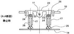
本発明の好適な実施の形態について図面を用いて説明する。図1は、本実施の形態におけるスイッチ装置の上面外観図である。図2は、図1で示すスイッチ装置のA−A断面図であり、スイッチノブを操作していない静止時の状態を示している。また、図3は、図1で示すスイッチ装置のA−A断面図であり、スイッチノブを操作した作動時の状態を示している。なお、前述した従来の技術に示した部材と同一又は類似する部材には、同一符号を付して説明を省略する。
【0012】
本実施の形態において特徴的なことは、図2および図3からも明らかな通り、スイッチノブ22とスイッチシャフト26が接続されていることである。この接続構造について詳細に説明すると、スイッチノブ22には従来の技術で示した突起部13(図7、図8参照)と同様の位置にシャフト接続用突起部23が形成されており、このシャフト接続用突起部23にはスイッチシャフト接続軸24が形成されている。スイッチシャフト26は、このスイッチシャフト接続軸24に接続することによって、スイッチノブ22の傾動復帰動作に従って移動することが可能となっている。また、スイッチシャフト26の左右には案内レール17が設置されており、スイッチシャフト26は、この案内レール17に左右方向の動きを規制されることによって直線的な移動をすることになる。したがって、タクトスイッチ25に対して常に垂直方向の押圧力を及ぼすことが可能となっている。
【0013】
以上のような構成、すなわち、スイッチノブ22とスイッチシャフト26を接続することによって、従来のスイッチ装置で発生していたスイッチノブ12とスイッチシャフト16の激突による打音発生を防止することができる。ここで、本実施の形態で示すスイッチ装置の構成を採用すると、スイッチシャフト26とタクトスイッチ25が激突することになるのであるが、本実施の形態では、このスイッチシャフト26とタクトスイッチ25の激突による打音発生を防止するために、タクトスイッチ25がスイッチシャフト26から押圧される部位を弾性部材で構成している。したがって、スイッチシャフト26がタクトスイッチ25に激突しても打音は発生せず、スイッチ操作時に作動音の静かなスイッチ装置を提供することが可能となるのである。なお、タクトスイッチ25に用いられる弾性部材としては、ゴムやシリコーンゴム等公知の弾性部材を用いることが可能である。
【0014】
さらに、本実施の形態における好適な作用として、従来のスイッチ装置と比較してスイッチノブ22のぐらつきが減少するという利点がある。このぐらつき減少によって、従来のスイッチ装置と比較してスイッチ操作時のフィーリングが向上するという効果がある。この点について、図4および図5を用いて説明する。ここで、図4中(a)は本実施の形態におけるスイッチ装置の上面外観図、(b)は(a)におけるB−B断面を示している。また、図5中(a)は従来のスイッチ装置におけるスイッチ装置の上面外観図、(b)は(a)におけるC−C断面を示している。
【0015】
図5で示す従来のスイッチ装置では、スイッチノブ12がスイッチ筐体10に形成されている回転軸11とスイッチノブ12の備える座面12aとで支えられるのみであった。したがって、従来のスイッチノブ12は、構造的に図5(a)で示す矢印(X)の方向にぐらつきを発生させてしまうという不具合を有していた。このぐらつきを解消するためには、座面12aの面積を広くするという対策が考えられるが、この方法では回転軸11と座面12aの摺動抵抗を増加させてしまうので、スイッチ操作のフィーリングを低下させてしまうことになり、従来の構造ではぐらつきを防止することが困難であった。
【0016】
一方、図4で示す本実施の形態におけるスイッチ装置であれば、スイッチノブ22はスイッチシャフト26に接続されており、さらにスイッチシャフト26は案内レール17に左右方向の動きを規制されているので、スイッチノブ22のぐらつきが発生しにくい構造となっている。したがって、本実施の形態によれば、スイッチノブ22のぐらつきを防止するとともにスイッチ操作時のフィーリングをも改善したスイッチ装置を提供することができる。
【0017】
なお、図4において、シャフト接続用突起部23は、スイッチシャフト26を挟むように2つ設けられているが、いずれか一方のみでもスイッチノブ22のぐらつきを防止することができる。
【0018】
また、本実施の形態では、シーソータイプのスイッチ装置を例示して説明したが、スイッチノブの一端部に支点を有し他端側を操作するタイプのスイッチ装置や多方向にスイッチノブが転倒するタイプのスイッチ装置等、あらゆるタイプのスイッチ装置に適用することが可能である。
【0019】
【発明の効果】
以上述べたように、本発明によれば、スイッチ装置の構造を大きく変更することなく打音の発生を抑制し、作動音の静かなスイッチ装置を提供することができる。
【0020】
また、スイッチノブとスイッチシャフトの接続をしたことでスイッチノブのぐらつき発生を防止することができたので、スイッチ操作時のフィーリングを改善したスイッチ装置を提供することができる。
【図面の簡単な説明】
【図1】 本実施の形態におけるスイッチ装置の上面外観図である。
【図2】 図1で示すスイッチ装置のA−A断面図であり、スイッチノブを操作していない静止時の状態を示している。
【図3】 図1で示すスイッチ装置のA−A断面図であり、スイッチノブを操作した作動時の状態を示している。
【図4】 (a)は本実施の形態におけるスイッチ装置の上面外観図、(b)は(a)におけるB−B断面を示している。
【図5】 (a)は従来のスイッチ装置におけるスイッチ装置の上面外観図、(b)は(a)におけるC−C断面を示している。
【図6】 従来のスイッチ装置の上面外観図である。
【図7】 図6で示すスイッチ装置のD−D断面図であり、スイッチノブを操作していない静止時の状態を示している。
【図8】 図6で示すスイッチ装置のD−D断面図であり、スイッチノブを操作した作動時の状態を示している。
【符号の説明】
10 スイッチ筐体、11 回転軸、12,22 スイッチノブ、12a 座面、13 突起部、14 プリント基板、15 タクトスイッチ(樹脂製)、16,26 スイッチシャフト、17 案内レール、23 シャフト接続用突起部、24 スイッチシャフト接続軸、25 タクトスイッチ(弾性部材製)。[0001]
BACKGROUND OF THE INVENTION
The present invention relates to a switch device, and more particularly to an improvement of a switch device characterized by preventing generation of switch sound when a switch knob is operated.
[0002]
[Prior art]
The switch device used for the operation panel of various electronic devices is a seesaw type that combines a tactile switch with a switch knob having a fulcrum at the center, and a type that has a fulcrum at one end of the switch knob and operates the other end. Etc., there exist various things. In particular, as various devices become more sophisticated and diversified in recent years, many devices having an automatic return function in which the switch knob automatically returns to the original position when the hand is released after operating the switch knob are often used. It has become like this.
[0003]
Such a conventional switch device will be described with reference to FIGS. 6, 7, and 8. FIG. FIG. 6 is a top external view of a conventional switch device. FIG. 7 is a DD cross-sectional view of the switch device shown in FIG. 6 and shows a stationary state in which the switch knob is not operated. FIG. 8 is a DD cross-sectional view of the switch device shown in FIG. 6 and shows a state when the switch knob is operated. These drawings illustrate a seesaw type switching device.
[0004]
In the conventional switch device, a
[0005]
The
[0006]
When the switch operator operates the
[0007]
[Patent Document 1]
Japanese Patent Laid-Open No. 11-86683
[Problems to be solved by the invention]
However, the conventional switch device has a problem in that when the
[0009]
The present invention has been made to solve the above-described problems, and suppresses the generation of a hitting sound without greatly changing the structure of the switch deviceand prevents the switch knob from wobbling. An object of the present invention is to provide a switching device with a quiet operation sound.
[0010]
[Means for Solving the Problems]
In order to solve the problems as described above, the switch device according to the present invention is installed so as to be tiltable about a rotation axis whose left-right direction is the axial direction, and has a function of automatically returning to the original position,Connecting the shaft connecting projection formed on the back side of the operator pressing portion of the switch knob, the shaft connecting projection formed on the shaft connecting projection and the axial direction of the switch shaft connecting to the switch shaft connecting shaft. And a switch shaft that moves according to the tilt return operation of the switch knob, wherein the shaft connection protrusion is a switch device formed on the left and right of the switch shaft so as to sandwich the switch shaft, It is installed on the left and right sides of the switch shaft so as to restrict the left and right movement of the switch shaft. And a tactile switch that is installed so as to be able to contact and separate from the switch shaft and that is electrically connected to and separated from the switch shaft by being pressed from the switch shaft, the tact switch from the switch shaft The part to be pressed is made of an elastic member.
[0011]
DETAILED DESCRIPTION OF THE INVENTION
Preferred embodiments of the present invention will be described with reference to the drawings. FIG. 1 is a top external view of the switch device according to the present embodiment. FIG. 2 is a cross-sectional view taken along line AA of the switch device shown in FIG. 1 and shows a stationary state in which the switch knob is not operated. FIG. 3 is a cross-sectional view taken along the line AA of the switch device shown in FIG. 1 and shows a state when the switch knob is operated. In addition, the same code | symbol is attached | subjected to the member similar or similar to the member shown to the prior art mentioned above, and description is abbreviate | omitted.
[0012]
What is characteristic in the present embodiment is that the
[0013]
By connecting the
[0014]
Furthermore, as a preferable action in the present embodiment, there is an advantage that the wobbling of the
[0015]
In the conventional switch device shown in FIG. 5, the
[0016]
On the other hand, in the switch device according to the present embodiment shown in FIG. 4, the
[0017]
In FIG. 4, two
[0018]
In this embodiment, the seesaw type switch device is described as an example. However, the switch knob has a fulcrum at one end of the switch knob and operates the other end, or the switch knob falls in multiple directions. The present invention can be applied to any type of switch device such as a type of switch device.
[0019]
【The invention's effect】
As described above, according to the present invention, it is possible to provide a switch device that suppresses the generation of a hitting sound and has a quiet operation sound without greatly changing the structure of the switch device.
[0020]
In addition, since the switch knob and the switch shaft are connected, it is possible to prevent the switch knob from wobbling, so that it is possible to provide a switch device with improved feeling when the switch is operated.
[Brief description of the drawings]
FIG. 1 is a top external view of a switch device according to an embodiment.
FIG. 2 is a cross-sectional view taken along line AA of the switch device shown in FIG. 1, showing a stationary state in which the switch knob is not operated.
FIG. 3 is a cross-sectional view taken along the line AA of the switch device shown in FIG. 1, and shows a state in operation when the switch knob is operated.
4A is a top external view of the switch device according to the present embodiment, and FIG. 4B is a cross-sectional view taken along line BB in FIG. 4A.
FIG. 5A is a top external view of a switch device in a conventional switch device, and FIG. 5B is a CC cross section in FIG.
FIG. 6 is a top external view of a conventional switch device.
7 is a cross-sectional view taken along the line DD of the switch device shown in FIG. 6 and shows a stationary state in which the switch knob is not operated.
FIG. 8 is a cross-sectional view taken along the line DD of the switch device shown in FIG. 6 and shows a state when the switch knob is operated.
[Explanation of symbols]
10 Switch housing, 11 Rotating shaft, 12, 22 Switch knob, 12a Seat surface, 13 Protruding part, 14 Printed circuit board, 15 Tact switch (made of resin), 16, 26 Switch shaft, 17 Guide rail, 23 Shaft connecting protrusion Part, 24 switch shaft connecting shaft, 25 tact switch (made of elastic member).
Claims (1)
Translated fromJapaneseスイッチノブの操作者押圧部の裏面側に形成されたシャフト接続用突起部と、
シャフト接続用突起部に形成され軸方向が左右方向のスイッチシャフト接続軸と、
前記スイッチシャフト接続軸と接続することにより、前記スイッチノブの傾動復帰動作に従って移動するスイッチシャフトと、を備え、
前記シャフト接続用突起部は、スイッチシャフトを挟むようにスイッチシャフトの左右に形成されたスイッチ装置であって、
前記スイッチシャフトの左右方向の動きを規制するようにスイッチシャフトの左右に設置され、スイッチシャフトの移動を上下方向に直線的に案内する案内レールと、
前記スイッチシャフトと接離可能に設置され、前記スイッチシャフトから押圧されることによって電気的接離を行うタクトスイッチと、
を備え、
前記タクトスイッチは、前記スイッチシャフトから押圧される部位が弾性部材で構成されていることを特徴とするスイッチ装置。A switch knob that is installed so as to be tiltable about the rotation axis in the left-right direction as the axis, and has an automatic return function to the original position;
A shaft connecting projection formed on the back side of the operator pressing portion of the switch knob;
A switch shaft connecting shaftformed in the shaft connecting projection and having an axial direction left and right ;
A switch shaft that moves according to a tilt return operation of the switch knob by connecting to the switch shaft connecting shaft;
The shaft connecting projection is a switch device formed on the left and right of the switch shaft so as to sandwich the switch shaft,
Guide rails that are installed on the left and right of the switch shaft so as to restrict the movement of the switch shaft in the left-right direction, and guide the movement of the switch shaft linearly in the up-down direction;
A tact switch that is installed so as to be able to contact and separate from the switch shaft, and performs electrical contact and separation by being pressed from the switch shaft,
With
In the tact switch, a portion pressed from the switch shaft is formed of an elastic member.
Priority Applications (3)
| Application Number | Priority Date | Filing Date | Title |
|---|---|---|---|
| JP2003186060AJP3850818B2 (en) | 2003-06-30 | 2003-06-30 | Switch device |
| CA2440297ACA2440297C (en) | 2003-06-30 | 2003-09-11 | Switch unit |
| US10/670,536US6756553B1 (en) | 2003-06-30 | 2003-09-25 | Switch unit |
Applications Claiming Priority (1)
| Application Number | Priority Date | Filing Date | Title |
|---|---|---|---|
| JP2003186060AJP3850818B2 (en) | 2003-06-30 | 2003-06-30 | Switch device |
Publications (2)
| Publication Number | Publication Date |
|---|---|
| JP2005019347A JP2005019347A (en) | 2005-01-20 |
| JP3850818B2true JP3850818B2 (en) | 2006-11-29 |
Family
ID=32501275
Family Applications (1)
| Application Number | Title | Priority Date | Filing Date |
|---|---|---|---|
| JP2003186060AExpired - Fee RelatedJP3850818B2 (en) | 2003-06-30 | 2003-06-30 | Switch device |
Country Status (3)
| Country | Link |
|---|---|
| US (1) | US6756553B1 (en) |
| JP (1) | JP3850818B2 (en) |
| CA (1) | CA2440297C (en) |
Families Citing this family (98)
| Publication number | Priority date | Publication date | Assignee | Title |
|---|---|---|---|---|
| US6726686B2 (en) | 1997-11-12 | 2004-04-27 | Sherwood Services Ag | Bipolar electrosurgical instrument for sealing vessels |
| US7435249B2 (en) | 1997-11-12 | 2008-10-14 | Covidien Ag | Electrosurgical instruments which reduces collateral damage to adjacent tissue |
| US6228083B1 (en) | 1997-11-14 | 2001-05-08 | Sherwood Services Ag | Laparoscopic bipolar electrosurgical instrument |
| US7582087B2 (en) | 1998-10-23 | 2009-09-01 | Covidien Ag | Vessel sealing instrument |
| US7118570B2 (en) | 2001-04-06 | 2006-10-10 | Sherwood Services Ag | Vessel sealing forceps with disposable electrodes |
| US7267677B2 (en) | 1998-10-23 | 2007-09-11 | Sherwood Services Ag | Vessel sealing instrument |
| US7364577B2 (en) | 2002-02-11 | 2008-04-29 | Sherwood Services Ag | Vessel sealing system |
| US20030109875A1 (en) | 1999-10-22 | 2003-06-12 | Tetzlaff Philip M. | Open vessel sealing forceps with disposable electrodes |
| EP1527747B1 (en) | 2001-04-06 | 2015-09-30 | Covidien AG | Electrosurgical instrument which reduces collateral damage to adjacent tissue |
| ES2262639T3 (en) | 2001-04-06 | 2006-12-01 | Sherwood Services Ag | SHUTTER AND DIVIDER OF GLASSES WITH BUMPER MEMBERS N OCONDUCTIVES. |
| US7931649B2 (en) | 2002-10-04 | 2011-04-26 | Tyco Healthcare Group Lp | Vessel sealing instrument with electrical cutting mechanism |
| US7276068B2 (en) | 2002-10-04 | 2007-10-02 | Sherwood Services Ag | Vessel sealing instrument with electrical cutting mechanism |
| US7270664B2 (en) | 2002-10-04 | 2007-09-18 | Sherwood Services Ag | Vessel sealing instrument with electrical cutting mechanism |
| US7799026B2 (en) | 2002-11-14 | 2010-09-21 | Covidien Ag | Compressible jaw configuration with bipolar RF output electrodes for soft tissue fusion |
| EP1601298B1 (en) | 2003-03-13 | 2016-09-07 | Covidien AG | Bipolar concentric electrode assembly for soft tissue fusion |
| CA2523675C (en) | 2003-05-01 | 2016-04-26 | Sherwood Services Ag | Electrosurgical instrument which reduces thermal damage to adjacent tissue |
| US7160299B2 (en) | 2003-05-01 | 2007-01-09 | Sherwood Services Ag | Method of fusing biomaterials with radiofrequency energy |
| JP5137230B2 (en) | 2003-05-15 | 2013-02-06 | コヴィディエン・アクチェンゲゼルシャフト | Tissue sealer with non-conductive variable stop member and method for sealing tissue |
| US7150749B2 (en) | 2003-06-13 | 2006-12-19 | Sherwood Services Ag | Vessel sealer and divider having elongated knife stroke and safety cutting mechanism |
| US7857812B2 (en) | 2003-06-13 | 2010-12-28 | Covidien Ag | Vessel sealer and divider having elongated knife stroke and safety for cutting mechanism |
| USD956973S1 (en) | 2003-06-13 | 2022-07-05 | Covidien Ag | Movable handle for endoscopic vessel sealer and divider |
| US7156846B2 (en) | 2003-06-13 | 2007-01-02 | Sherwood Services Ag | Vessel sealer and divider for use with small trocars and cannulas |
| US9848938B2 (en) | 2003-11-13 | 2017-12-26 | Covidien Ag | Compressible jaw configuration with bipolar RF output electrodes for soft tissue fusion |
| US7367976B2 (en) | 2003-11-17 | 2008-05-06 | Sherwood Services Ag | Bipolar forceps having monopolar extension |
| US7131970B2 (en) | 2003-11-19 | 2006-11-07 | Sherwood Services Ag | Open vessel sealing instrument with cutting mechanism |
| US7500975B2 (en) | 2003-11-19 | 2009-03-10 | Covidien Ag | Spring loaded reciprocating tissue cutting mechanism in a forceps-style electrosurgical instrument |
| US7811283B2 (en) | 2003-11-19 | 2010-10-12 | Covidien Ag | Open vessel sealing instrument with hourglass cutting mechanism and over-ratchet safety |
| US7442193B2 (en) | 2003-11-20 | 2008-10-28 | Covidien Ag | Electrically conductive/insulative over-shoe for tissue fusion |
| US7780662B2 (en) | 2004-03-02 | 2010-08-24 | Covidien Ag | Vessel sealing system using capacitive RF dielectric heating |
| JP2006069174A (en)* | 2004-09-06 | 2006-03-16 | Juken Fine Tool:Kk | Mold for molding plastic filter |
| US7195631B2 (en) | 2004-09-09 | 2007-03-27 | Sherwood Services Ag | Forceps with spring loaded end effector assembly |
| US7540872B2 (en) | 2004-09-21 | 2009-06-02 | Covidien Ag | Articulating bipolar electrosurgical instrument |
| US7955332B2 (en) | 2004-10-08 | 2011-06-07 | Covidien Ag | Mechanism for dividing tissue in a hemostat-style instrument |
| CA2485278C (en)* | 2004-10-19 | 2012-05-01 | Kenneth Brad Hillman | Manual reset switch cover assembly |
| US7909823B2 (en) | 2005-01-14 | 2011-03-22 | Covidien Ag | Open vessel sealing instrument |
| US7686804B2 (en) | 2005-01-14 | 2010-03-30 | Covidien Ag | Vessel sealer and divider with rotating sealer and cutter |
| JP4456012B2 (en)* | 2005-01-24 | 2010-04-28 | 株式会社東海理化電機製作所 | Switch device |
| US7491202B2 (en) | 2005-03-31 | 2009-02-17 | Covidien Ag | Electrosurgical forceps with slow closure sealing plates and method of sealing tissue |
| JP2006331999A (en)* | 2005-05-30 | 2006-12-07 | Toyoda Gosei Co Ltd | Rocking switch |
| US7922953B2 (en) | 2005-09-30 | 2011-04-12 | Covidien Ag | Method for manufacturing an end effector assembly |
| US7789878B2 (en) | 2005-09-30 | 2010-09-07 | Covidien Ag | In-line vessel sealer and divider |
| US7722607B2 (en) | 2005-09-30 | 2010-05-25 | Covidien Ag | In-line vessel sealer and divider |
| ES2381560T3 (en) | 2005-09-30 | 2012-05-29 | Covidien Ag | Insulating sleeve for electrosurgical forceps |
| CA2561034C (en) | 2005-09-30 | 2014-12-09 | Sherwood Services Ag | Flexible endoscopic catheter with an end effector for coagulating and transfecting tissue |
| US7879035B2 (en) | 2005-09-30 | 2011-02-01 | Covidien Ag | Insulating boot for electrosurgical forceps |
| US8734443B2 (en) | 2006-01-24 | 2014-05-27 | Covidien Lp | Vessel sealer and divider for large tissue structures |
| US8298232B2 (en) | 2006-01-24 | 2012-10-30 | Tyco Healthcare Group Lp | Endoscopic vessel sealer and divider for large tissue structures |
| US8882766B2 (en) | 2006-01-24 | 2014-11-11 | Covidien Ag | Method and system for controlling delivery of energy to divide tissue |
| US8241282B2 (en) | 2006-01-24 | 2012-08-14 | Tyco Healthcare Group Lp | Vessel sealing cutting assemblies |
| US7776037B2 (en) | 2006-07-07 | 2010-08-17 | Covidien Ag | System and method for controlling electrode gap during tissue sealing |
| US8597297B2 (en) | 2006-08-29 | 2013-12-03 | Covidien Ag | Vessel sealing instrument with multiple electrode configurations |
| US8070746B2 (en) | 2006-10-03 | 2011-12-06 | Tyco Healthcare Group Lp | Radiofrequency fusion of cardiac tissue |
| JP4582084B2 (en)* | 2006-12-05 | 2010-11-17 | 住友電装株式会社 | Seesaw switch |
| USD649249S1 (en) | 2007-02-15 | 2011-11-22 | Tyco Healthcare Group Lp | End effectors of an elongated dissecting and dividing instrument |
| US7554049B2 (en) | 2007-03-20 | 2009-06-30 | Denso Corporation | Rocking switch unit |
| US8267935B2 (en)* | 2007-04-04 | 2012-09-18 | Tyco Healthcare Group Lp | Electrosurgical instrument reducing current densities at an insulator conductor junction |
| US7877853B2 (en) | 2007-09-20 | 2011-02-01 | Tyco Healthcare Group Lp | Method of manufacturing end effector assembly for sealing tissue |
| US7877852B2 (en) | 2007-09-20 | 2011-02-01 | Tyco Healthcare Group Lp | Method of manufacturing an end effector assembly for sealing tissue |
| US8235992B2 (en) | 2007-09-28 | 2012-08-07 | Tyco Healthcare Group Lp | Insulating boot with mechanical reinforcement for electrosurgical forceps |
| US8235993B2 (en) | 2007-09-28 | 2012-08-07 | Tyco Healthcare Group Lp | Insulating boot for electrosurgical forceps with exohinged structure |
| US8221416B2 (en) | 2007-09-28 | 2012-07-17 | Tyco Healthcare Group Lp | Insulating boot for electrosurgical forceps with thermoplastic clevis |
| US8267936B2 (en) | 2007-09-28 | 2012-09-18 | Tyco Healthcare Group Lp | Insulating mechanically-interfaced adhesive for electrosurgical forceps |
| US8251996B2 (en) | 2007-09-28 | 2012-08-28 | Tyco Healthcare Group Lp | Insulating sheath for electrosurgical forceps |
| US9023043B2 (en) | 2007-09-28 | 2015-05-05 | Covidien Lp | Insulating mechanically-interfaced boot and jaws for electrosurgical forceps |
| US8236025B2 (en) | 2007-09-28 | 2012-08-07 | Tyco Healthcare Group Lp | Silicone insulated electrosurgical forceps |
| AU2008221509B2 (en) | 2007-09-28 | 2013-10-10 | Covidien Lp | Dual durometer insulating boot for electrosurgical forceps |
| US8764748B2 (en) | 2008-02-06 | 2014-07-01 | Covidien Lp | End effector assembly for electrosurgical device and method for making the same |
| US8623276B2 (en) | 2008-02-15 | 2014-01-07 | Covidien Lp | Method and system for sterilizing an electrosurgical instrument |
| US8469956B2 (en) | 2008-07-21 | 2013-06-25 | Covidien Lp | Variable resistor jaw |
| US8162973B2 (en) | 2008-08-15 | 2012-04-24 | Tyco Healthcare Group Lp | Method of transferring pressure in an articulating surgical instrument |
| US8257387B2 (en) | 2008-08-15 | 2012-09-04 | Tyco Healthcare Group Lp | Method of transferring pressure in an articulating surgical instrument |
| US9603652B2 (en) | 2008-08-21 | 2017-03-28 | Covidien Lp | Electrosurgical instrument including a sensor |
| US8795274B2 (en) | 2008-08-28 | 2014-08-05 | Covidien Lp | Tissue fusion jaw angle improvement |
| US8784417B2 (en) | 2008-08-28 | 2014-07-22 | Covidien Lp | Tissue fusion jaw angle improvement |
| US8317787B2 (en) | 2008-08-28 | 2012-11-27 | Covidien Lp | Tissue fusion jaw angle improvement |
| US8303582B2 (en) | 2008-09-15 | 2012-11-06 | Tyco Healthcare Group Lp | Electrosurgical instrument having a coated electrode utilizing an atomic layer deposition technique |
| US8968314B2 (en) | 2008-09-25 | 2015-03-03 | Covidien Lp | Apparatus, system and method for performing an electrosurgical procedure |
| US8535312B2 (en) | 2008-09-25 | 2013-09-17 | Covidien Lp | Apparatus, system and method for performing an electrosurgical procedure |
| US9375254B2 (en) | 2008-09-25 | 2016-06-28 | Covidien Lp | Seal and separate algorithm |
| US8142473B2 (en) | 2008-10-03 | 2012-03-27 | Tyco Healthcare Group Lp | Method of transferring rotational motion in an articulating surgical instrument |
| US8469957B2 (en) | 2008-10-07 | 2013-06-25 | Covidien Lp | Apparatus, system, and method for performing an electrosurgical procedure |
| US8016827B2 (en) | 2008-10-09 | 2011-09-13 | Tyco Healthcare Group Lp | Apparatus, system, and method for performing an electrosurgical procedure |
| US8636761B2 (en) | 2008-10-09 | 2014-01-28 | Covidien Lp | Apparatus, system, and method for performing an endoscopic electrosurgical procedure |
| US8486107B2 (en) | 2008-10-20 | 2013-07-16 | Covidien Lp | Method of sealing tissue using radiofrequency energy |
| US8197479B2 (en) | 2008-12-10 | 2012-06-12 | Tyco Healthcare Group Lp | Vessel sealer and divider |
| US8114122B2 (en) | 2009-01-13 | 2012-02-14 | Tyco Healthcare Group Lp | Apparatus, system, and method for performing an electrosurgical procedure |
| US8187273B2 (en) | 2009-05-07 | 2012-05-29 | Tyco Healthcare Group Lp | Apparatus, system, and method for performing an electrosurgical procedure |
| US8246618B2 (en) | 2009-07-08 | 2012-08-21 | Tyco Healthcare Group Lp | Electrosurgical jaws with offset knife |
| US8133254B2 (en) | 2009-09-18 | 2012-03-13 | Tyco Healthcare Group Lp | In vivo attachable and detachable end effector assembly and laparoscopic surgical instrument and methods therefor |
| US8112871B2 (en) | 2009-09-28 | 2012-02-14 | Tyco Healthcare Group Lp | Method for manufacturing electrosurgical seal plates |
| US9113940B2 (en) | 2011-01-14 | 2015-08-25 | Covidien Lp | Trigger lockout and kickback mechanism for surgical instruments |
| USD680220S1 (en) | 2012-01-12 | 2013-04-16 | Coviden IP | Slider handle for laparoscopic device |
| CN105451670B (en) | 2013-08-07 | 2018-09-04 | 柯惠有限合伙公司 | Surgery forceps |
| US10231777B2 (en) | 2014-08-26 | 2019-03-19 | Covidien Lp | Methods of manufacturing jaw members of an end-effector assembly for a surgical instrument |
| US10987159B2 (en) | 2015-08-26 | 2021-04-27 | Covidien Lp | Electrosurgical end effector assemblies and electrosurgical forceps configured to reduce thermal spread |
| US10213250B2 (en) | 2015-11-05 | 2019-02-26 | Covidien Lp | Deployment and safety mechanisms for surgical instruments |
| JP6652875B2 (en)* | 2016-04-06 | 2020-02-26 | アルプスアルパイン株式会社 | Push-pull switch device |
| US11166759B2 (en) | 2017-05-16 | 2021-11-09 | Covidien Lp | Surgical forceps |
Family Cites Families (8)
| Publication number | Priority date | Publication date | Assignee | Title |
|---|---|---|---|---|
| JPS6326893Y2 (en)* | 1980-08-13 | 1988-07-21 | ||
| US5149924A (en)* | 1989-05-05 | 1992-09-22 | Priesemuth W | Multiple contact switch arrangement |
| DE4425154C1 (en)* | 1994-07-16 | 1995-10-19 | Valeo Borg Instr Verw Gmbh | Push-button actuated switch with elongated pushbutton and transmission lever |
| US5957273A (en)* | 1997-07-22 | 1999-09-28 | Ut Automotive Dearborn, Inc. | Universal switch |
| JPH1186683A (en) | 1997-09-08 | 1999-03-30 | Matsushita Electric Ind Co Ltd | Swing operation type switch device |
| EP0957498B1 (en)* | 1998-05-11 | 2006-08-23 | Delphi Technologies Inc. | Power window switch |
| DE19912086A1 (en)* | 1999-03-18 | 2000-09-21 | Eaton Corp | Stroke-slide switch |
| JP3971159B2 (en)* | 2001-11-07 | 2007-09-05 | 株式会社東海理化電機製作所 | Switch device |
- 2003
- 2003-06-30JPJP2003186060Apatent/JP3850818B2/ennot_activeExpired - Fee Related
- 2003-09-11CACA2440297Apatent/CA2440297C/ennot_activeExpired - Fee Related
- 2003-09-25USUS10/670,536patent/US6756553B1/ennot_activeExpired - Fee Related
Also Published As
| Publication number | Publication date |
|---|---|
| US6756553B1 (en) | 2004-06-29 |
| CA2440297A1 (en) | 2004-12-30 |
| CA2440297C (en) | 2012-06-26 |
| JP2005019347A (en) | 2005-01-20 |
Similar Documents
| Publication | Publication Date | Title |
|---|---|---|
| JP3850818B2 (en) | Switch device | |
| JP4217546B2 (en) | switch | |
| EP1760742B1 (en) | Switch device and steering switch apparatus equipped with the switch device | |
| CN105659347B (en) | Micro switch control device | |
| JP3794163B2 (en) | Circuit breaker | |
| CN113451068A (en) | Switch assembly, automobile information entertainment system and vehicle | |
| CN113525311B (en) | Switchgear | |
| US10490371B2 (en) | Electrical switch | |
| CN108780715A (en) | rocker switch | |
| JP2001229788A (en) | Lever switch and composite switch using the same | |
| JP2005276650A (en) | Switch device | |
| CN210120069U (en) | Switch structure and steering wheel | |
| KR101555378B1 (en) | Composite switch unit | |
| JP4736972B2 (en) | Multi-directional operation switch | |
| JP4439705B2 (en) | Push button switch | |
| JP2001014980A (en) | Seesaw switch | |
| JPH09288935A (en) | Seesaw switch | |
| US20250291434A1 (en) | Mouse button structure and mouse device having the same | |
| JP2004206926A (en) | Switchgear | |
| JP2005056703A (en) | Moving element of switch | |
| WO2025109889A1 (en) | Switch device | |
| WO2023220705A2 (en) | Translational mouse key structure and mouse device having the same | |
| JP3113496B2 (en) | Quick-acting switch device | |
| JP2002334632A (en) | Push button switch device | |
| JPH0617067U (en) | Switch device |
Legal Events
| Date | Code | Title | Description |
|---|---|---|---|
| A977 | Report on retrieval | Free format text:JAPANESE INTERMEDIATE CODE: A971007 Effective date:20060223 | |
| A131 | Notification of reasons for refusal | Free format text:JAPANESE INTERMEDIATE CODE: A131 Effective date:20060228 | |
| A521 | Request for written amendment filed | Free format text:JAPANESE INTERMEDIATE CODE: A523 Effective date:20060427 | |
| A02 | Decision of refusal | Free format text:JAPANESE INTERMEDIATE CODE: A02 Effective date:20060523 | |
| A521 | Request for written amendment filed | Free format text:JAPANESE INTERMEDIATE CODE: A523 Effective date:20060703 | |
| A911 | Transfer to examiner for re-examination before appeal (zenchi) | Free format text:JAPANESE INTERMEDIATE CODE: A911 Effective date:20060728 | |
| TRDD | Decision of grant or rejection written | ||
| A01 | Written decision to grant a patent or to grant a registration (utility model) | Free format text:JAPANESE INTERMEDIATE CODE: A01 Effective date:20060815 | |
| A61 | First payment of annual fees (during grant procedure) | Free format text:JAPANESE INTERMEDIATE CODE: A61 Effective date:20060830 | |
| R150 | Certificate of patent or registration of utility model | Free format text:JAPANESE INTERMEDIATE CODE: R150 | |
| LAPS | Cancellation because of no payment of annual fees |